Generalities on Metrology and Microwave Holography
|
|
|
- Pauline Cunningham
- 6 years ago
- Views:
Transcription

1 Generalities on Metrology and Microwave Holography Richard Prestage National Radio Astronomy Observatory Second Sardinian Summer School on Radio Astronomy and Radio Science
2 Outline of Talk Part I: General Metrology largely aimed at telescope pointing Types of antenna Quantities which affect telescope performance Stability criteria Approaches to metrology and instrumentation Part II: Microwave Holography measuring and setting the telescope surface Traditional (with phase, satellite) holography Near-field (with phase, beacon) holography Phase retrieval ( out-of-focus ) holography Second Sardinian Summer School on Single-Dish Radio Astronomy and Radio Science 2


3 Antenna Types long wavelength arrays centimeter transit cm/mm wave antenna millimeter antenna This talk will focus on the metrology requirements for antenna types 3 and 4 Second Sardinian Summer School on Single-Dish Radio Astronomy and Radio Science 3
4 Quantities to be Controlled Most telescopes perform as an ideal telescope at the low end of their frequency range. To observe at high frequencies, we need to measure and correct for departures of the telescope from ideal behavior: Pointing Collimation (focus) Surface Accuracy (wavefront phase errors) Path Length In the presence of: Gravity Temperature Wind Second Sardinian Summer School on Single-Dish Radio Astronomy and Radio Science 4
5 Departures from Ideal (I) [Refraction] Misalignment of the antenna structure (e.g. non-perpendicularity of the Az and El axes) May change (slowly) with time e.g. effects due to non-flatness of azimuth track. Deformations due to gravity (affects all four components). Most well behaved deformation; depends only on elevation angle. Second Sardinian Summer School on Single-Dish Radio Astronomy and Radio Science 5
6 Departures from Ideal (II) The effect of temperature change over time and location in the structure is to distort the optical alignment. Although telescopes are designed to minimize these effects, they can still be substantial. While temperature effects are repeatable, the state of the structure (distribution of temperatures, whether the structure is in thermodynamic equilibrium) is not well known. Wind loading can cause structural loads that significantly distort the telescope (i.e. cause the optical properties to change). Again, the effects are repeatable, but the flow field will not be well known. Structural vibrations can be excited by wind or servo system drives. For the GBT these vibrations can be significant, and have modal frequencies from 0.6Hz and up. The largest magnitude motions are in the feedarm assembly. Second Sardinian Summer School on Single-Dish Radio Astronomy and Radio Science 6
7 Stability Criteria Pointing Errors The normalized power gain g can be written as: ρ g( ρ) = exp 4ln(2) θ where ρ is the angular displacement from the beam center. In most cases the sensitivity lost through the reduction of mean gain <g> can be recovered by additional integration. fluctuations in gain have much worse consequences than the mean gain loss, both in terms of data quality and operational efficiency (Condon, 2003). 2 σ θ 10% flux errors: 5% flux errors: σ θ Second Sardinian Summer School on Single-Dish Radio Astronomy and Radio Science 7
8 Stability Criteria Focus Errors variation of relative power gain g a resulting from axial defocusing is given by: g A = exp f 4ln(2) θ A 2 Where θ A is the FWHM beamwidth in axial focus. g A > 0.99 for good focusing: axial focusing error < λ/16 (GBT) For a typical Cassegrain telescope f < λ/10. Axial focusing beamwidth in wavelengths is roughly proportional to (f/d) 2 and independent of D. Second Sardinian Summer School on Single-Dish Radio Astronomy and Radio Science 8
9 Stability Criteria - Wavefront Phase Error If the rms deviation from the ideal aperture is ε and the error correlation length is much smaller than the aperture diameter, the aperture efficiency is multiplied by the factor (Ruze 1966): η S exp 4πε λ 2 The traditional requirement for the efficiency η s of a good aperture is: ε < λ/16, so η s 0.54 A looser criterion for usable performance is that the forward gain, which is proportional to η s / λ 2, not decline as wavelength decreases. This implies: ε < λ/4π, so η s 0.37 Second Sardinian Summer School on Single-Dish Radio Astronomy and Radio Science 9
10 Typical Values Pointing accuracy λ/d Surface accuracy λ Tel. λ D θ θ ε GBT 3mm 100m µm SRT 3mm 65m µm ALMA 1.3mm 12m µm ALMA 350µm 12m µm Second Sardinian Summer School on Single-Dish Radio Astronomy and Radio Science 10
11 Error Budget Pointing (LMT) Source and Type of Error Uncorr. ( ) Corr. ( ) Method Environmental influences(quasi-static) a) Gravity Deformation Foundation << << Azimuth Rotation Structure << << Elevation Rotation Structure < LUT b) Wind Deformation (10 m/sec) Foundation << << Elevation FBC Cross Elevation FBC c) Thermal Deformation Foundation << << Azimuth Rotation Structure < FBC Elevation Rotation Structure < FBC Environmental Influences (Dynamic) Gusts on Servo Gusts on Structure Mechanical Alignment FBC Servo 0.3 Margin 0.3 Overall Pointing Error 0.75 Second Sardinian Summer School on Single-Dish Radio Astronomy and Radio Science 11
12 Error Budget Surface (LMT) Source and Type of Error Uncorr. (µm) Corr. (µm) Method Environmental influences(steady-state) a) Gravity Deformation BUS LUT Panels b) Wind Deformation (10 m/sec) BUS PANELS 6 6 Subreflector Lateral Offset Subreflector Defocus 6 6 c) Thermal Deformation BUS FBC PANELS Reflector Manufacturing Panels Subreflector Mechanical Alignment Panels Subreflector Margin 25 Overall Surface Error Budget 69 Second Sardinian Summer School on Single-Dish Radio Astronomy and Radio Science 12
13 Approaches to Metrology - Pointing Astronomically-defined pointing models, and offset pointing/focus calibration observations Temperature sensors to measure and compensate for thermal deformations Inclinometers to measure tilts / antenna deformations Quadrant Detector to measure relative location of subreflector [Use of laser rangefinders to measure absolute position of optical elements GBT] Second Sardinian Summer School on Single-Dish Radio Astronomy and Radio Science 13
14 Approaches to Metrology - Surface Use of passive means (insulation; homology) Photogrammetry for initial panel setting Microwave holography for static actuator zero-point measurements Use of FEA models / LUT for repeatable gravitational deformations Phase-retrieval holography to correct for residual gravitational deformations, and measure real-time thermal deformations Use of temperature sensors and FEA model to predict thermal deformations Direct measurement of relative actuator positions prototype, SRT [ Use of laser rangefinders for closed-loop control of actuators GBT] Second Sardinian Summer School on Single-Dish Radio Astronomy and Radio Science 14
15 Flexible Body Control Use auxiliary sensors in addition to main axes encoders. Modify indicated position to correct as well as possible for deformations in the structure Include these corrections into position loop. Second Sardinian Summer School on Single-Dish Radio Astronomy and Radio Science 15
16 Current State of the Art Conventional (astronomically derived) pointing models; offset pointing with calibration measurements Aided by thermal models and (real-time) inclinometry Open-loop control of actuators based on FEA models and LUTs Microwave holography to set actuator zero-points Residual gravitational terms and slowly varying large-scale thermal errors measured via out-of-focus holography SRT aiming for close-loop control with localized actuator displacement sensors Second Sardinian Summer School on Single-Dish Radio Astronomy and Radio Science 16

 Structure thermal distortions Vertical air lapse Second Sardinian Summer School on")
17 Structural/Air Temperature Sensors - GBT YSI 083 thermistors YSI 4800LC Thermistor Linearizing Circuit 0.15 C accuracy, -35 to 40 C 0.05 C interchangable accuracy 0.01 C resolution, 1 sec sampling 19 structure sensors 5 air sensors (forced convection cells, ~ 5 sec time constant) Structure thermal distortions Vertical air lapse Second Sardinian Summer School on Single-Dish Radio Astronomy and Radio Science 17


18 Temperature Sensors BUS R.Side EL Bearing Second Sardinian Summer School on Single-Dish Radio Astronomy and Radio Science 18


19 Structural Temperatures Second Sardinian Summer School on Single-Dish Radio Astronomy and Radio Science 19
20 Elevation Model Results Second Sardinian Summer School on Single-Dish Radio Astronomy and Radio Science 20


21 Inclinometers / Linear Sensors - ALMA Linear sensors measure to ends of CFRP encoder mount reference structure Second Sardinian Summer School on Single-Dish Radio Astronomy and Radio Science 21
22 Inclinometers - ALMA Second Sardinian Summer School on Single-Dish Radio Astronomy and Radio Science 22

23 Inclinometers - GBT AG gas-damped capacitive readout type from Wyler Zeromatic 2-axis (horizontal plane), both elevation bearings 0.1 short-term accuracy, 0.01 resolution ~1 sec damping, 17 Hz resonance 5 Hz sampling rate, 0.3 noise at 5 Hz Second Sardinian Summer School on Single-Dish Radio Astronomy and Radio Science 23


24 Inclinometers - GBT Accelerometer Cube Elevation Bearing Casting Three Point, Spherical Washer and Shim Leveled Mount Y Inclinometer X Inclinometer Second Sardinian Summer School on Single-Dish Radio Astronomy and Radio Science 24
25 Before and After Track Repair Second Sardinian Summer School on Single-Dish Radio Astronomy and Radio Science 25
26 Part II: Microwave Holography for Antenna Surface Measurements Second Sardinian Summer School on Single-Dish Radio Astronomy and Radio Science 26
27 Homologous Design Second Sardinian Summer School on Single-Dish Radio Astronomy and Radio Science 27

28 Homologous Design Second Sardinian Summer School on Single-Dish Radio Astronomy and Radio Science 28

29 Surface Adjustment Second Sardinian Summer School on Single-Dish Radio Astronomy and Radio Science 29
30 Quantifying Telescope Performance Two theorems: Reciprocity Theorem: Angular response of a radio telescope when used as a transmitting antenna is the same as when it is used as a receiving antenna Fourier Transform theorem: Far field electric field pattern is the Fourier transform of the aperture plane distribution Two main causes of loss: Losses related to the amplitude of the electric field Losses due to the phase of the electric field Second Sardinian Summer School on Single-Dish Radio Astronomy and Radio Science 30

31 Reciprocity Theorem Performance of the antenna when collecting radiation from a point source at infinity may be studied by considering its properties as a transmitter Second Sardinian Summer School on Single-Dish Radio Astronomy and Radio Science 31


32 Fourier Transform Relationship A(x,y) B(u,v) Far-field beam pattern is Fourier transform of aperture plane electric field distribution Second Sardinian Summer School on Single-Dish Radio Astronomy and Radio Science 32
33 Illumination efficiency taper and spillover Idealized uniform illumination 33

 for 11dB edge taper η a = η t η s = ~ 0.")
34 Illumination efficiency taper and spillover blue = taper loss, red = spillover loss Gaussian-illuminated zero phase error unblocked circular antenna: η a = η t η s = (maximum) for 11dB edge taper η a = η t η s = ~ 0.7 for ~15dB edge taper (GBT) 34


35 Ideal Telescope with Edge Taper Second Sardinian Summer School on Single-Dish Radio Astronomy and Radio Science 35
 may have predictable effects on beam pattern (e.g. astigmatism) Distribution of small-scale errors is generally unknown Second Sardinian Summer School on Single-Dish Radio Astronomy and Radio Science 36")
36 Real Telescope with Phase Losses Amplitude of electric field is largely unchanged Irregularities (deformations) in mirrors and misalignments cause phase errors => phase losses. Large scale errors (mis-alignments) may have predictable effects on beam pattern (e.g. astigmatism) Distribution of small-scale errors is generally unknown Second Sardinian Summer School on Single-Dish Radio Astronomy and Radio Science 36

37 Surface Irregularities Second Sardinian Summer School on Single-Dish Radio Astronomy and Radio Science 37
38 Phase Errors Second Sardinian Summer School on Single-Dish Radio Astronomy and Radio Science 38
39 Phase Losses Error distribution modeled by Ruze Ruze formula: ε = rms surface error η p = exp[(-4πε/λ) 2 ] pedestal θ p ~ Dθ/L η a down by 3dB for ε = λ/16 acceptable performance ε = λ/4π Second Sardinian Summer School on Single-Dish Radio Astronomy and Radio Science 39

40 Far Field Beam Pattern Maximum aperture efficiency η t η s (feed illumination) ~ 0.7 Large-scale phase errors (e.g. misalignment of secondary) affect main beam and near-in side lobes Random surface errors cause loss of efficiency and large scale error pedestal Can use Ruze formula to define equivalent wavefront error Second Sardinian Summer School on Single-Dish Radio Astronomy and Radio Science 40
41 Traditional (phase-reference) holography Dedicated receiver to look at a geostationary satellite Second dish (or reference antenna) provides phase reference Measure amplitude and phase of far-field beam pattern Fourier transform to determine amplitude and phase of aperture illumination Standard Technique which has been in use for ~ 35 years (see e.g. Bennett et al. 1976). These examples from the GBT (Hunter et al. 2011). Second Sardinian Summer School on Single-Dish Radio Astronomy and Radio Science 41
42 B(u,v) = ΣA(x,y) exp[2πj(xu+yv)] where B = beam, A = aperture u,v are angles; x,y are distances Second Sardinian Summer School on Single-Dish Radio Astronomy and Radio Science 42

43 Second Sardinian Summer School on Single-Dish Radio Astronomy and Radio Science 43
44 Phase Reference Holography Advantages: Can be performed at reasonable elevation angles. High spatial resolution over the dish. High accuracy (~60µm for GBT system). Disadvantages: Generally can only be performed at one elevation. Long (hours) data acquisition time. Requires dedicated hardware Receiver requires unusually high dynamic range (70dB). Second Sardinian Summer School on Single-Dish Radio Astronomy and Radio Science 44

 Linux backend,")

45 Phase Reference Holography Basic method: Measure complex beam pattern via interferometry Fourier transform to get phase and amplitude of E-field Convert phase to surface error GBT Ku-band holography system re-commissioned (December 2008): Two room-temp. LNBs, 10 khz filter and digital correlator New DROs with Digital PLLs (stability) Linux backend, sample rate = 28 Hz Allows 200-column, 2 x2 maps in 3 hours Reference signal path Main signal path Reference horn at top of feedarm Main receiver in Gregorian turret Second Sardinian Summer School on Single-Dish Radio Astronomy and Radio Science 45
 Typical phase stability (system + atmosphere) <2 rms in 36ms integrations Galaxy 28 50 MHz Second Sardinian Summer")
46 Satellite Target Galaxy 28 = geostationary TV satellite Elevation = 44 o, well-behaved diurnal path GHz beacon (stable to < 1 khz) Typical phase stability (system + atmosphere) <2 rms in 36ms integrations Galaxy MHz Second Sardinian Summer School on Single-Dish Radio Astronomy and Radio Science 46


47 Holography Map Showing Panel Locations Second Sardinian Summer School on Single-Dish Radio Astronomy and Radio Science 47

48 Progression of Surface Adjustments Second Sardinian Summer School on Single-Dish Radio Astronomy and Radio Science 48

49 Second Sardinian Summer School on Single-Dish Radio Astronomy and Radio Science 49

50 Comparison to known panel errors Second Sardinian Summer School on Single-Dish Radio Astronomy and Radio Science 50
 Patch of 128 bad actuators (now fixed power supply problem)")
51 Recent (not ideal) Results Non-repaired actuators (due to structural inspections) Patch of 128 bad actuators (now fixed power supply problem) Ice damage
52 Near-Field (Beacon) Holography Similar to traditional with-phase holography. Use a radio beacon in the near-field (Fresnel region) of the antenna under test. Use of near field causes a rapid variation of phase across the aperture (Baars et al. 2007). Largely corrected for by displacing the feed from the primary focus. Residual correction applied to the aperture phase distribution after the Fourier transform. Higher order terms collected into a variable ε: A( x, y) B( u, v)exp{ ik( ux + vy) e ikε The terms in ε modify the direct Fourier transform dudv Second Sardinian Summer School on Single-Dish Radio Astronomy and Radio Science 52
53 Near-Field(Beacon) Holography Advantages: Nearby beacon allows high S/N, high-resolution maps Maps can be obtained relatively quickly (less than one hour) Beacon can be chosen to have convenient frequency/location Disadvantages: Maps obtained at a single, low elevation Requires dedicated hardware Possibility of multiple reflections from ground or near-by structures Second Sardinian Summer School on Single-Dish Radio Astronomy and Radio Science 53


54 Near-Field (Beacon) Holography - ALMA Second Sardinian Summer School on Single-Dish Radio Astronomy and Radio Science 54


55 Near-field (Beacon) Holography Second Sardinian Summer School on Single-Dish Radio Astronomy and Radio Science 55
56 Phase Retrieval (Out of Focus) Holography Measure power only (instead of amplitude and phase) of far-field beam pattern on bright astronomical calibrator Without the amplitude/phase, cannot do the inverse Fourier transform to get aperture plane values. Instead assume aperture amplitude and phase; do forward transform to predict beam pattern. Iteratively adjust aperture phase, varying phase until predicted beam map is in good agreement with observed map. Second Sardinian Summer School on Single-Dish Radio Astronomy and Radio Science 56
![B(u,v) = ΣA(x,y) exp[2πj(xu+yv)] where B = beam, A = aperture u,v are angles; x,y are](/docs-images/78/78205840/images/57-1.jpg "distances Second Sardinian Summer School on Single-Dish Radio Astronomy and Radio")
57 B(u,v) = ΣA(x,y) exp[2πj(xu+yv)] where B = beam, A = aperture u,v are angles; x,y are distances Second Sardinian Summer School on Single-Dish Radio Astronomy and Radio Science 57

58 Phase Retrieval (Out of Focus) Holography Second Sardinian Summer School on Single-Dish Radio Astronomy and Radio Science 58
59 Phase Retrieval (Out of Focus) Holography Advantages: Uses same receiver as used for astronomical measurements Measure the complete optical aberrations in the telescope Rapid maps (< five minutes) As a function of elevation As a function of time Disadvantages: Low spatial resolution (cannot resolve individual actuators) Second Sardinian Summer School on Single-Dish Radio Astronomy and Radio Science 59
60 Technique Make three Nyquist-sampled beam maps, one in focus, one each ~ five wavelengths radial defocus Model surface errors (phase errors) as combinations of low-order Zernike polynomials. Perform forward transform to predict observed beam maps (correctly accounting for phase effects of defocus) Sample model map at locations of actual maps (no need for regridding) Adjust coefficients to minimize difference between model and actual beam maps. Second Sardinian Summer School on Single-Dish Radio Astronomy and Radio Science 60
61 Typical data Q-band (43 GHz)

62 Typical data: before (rms = 370 µm)
63 OOF technique Measure power only (instead of phase and amplitude), recover phase by modeling A classic non-linear inverse problem: The forward model Conceptually relatively simple: only requires an FFT Beam switching, non-point like sources, atmospheric effects, off-axis pixels, etc., make it complex Parametrisation of surface errors Zernike polynomials Likelihood of data given model Take normally distributed errors Pointing errors, residual atmospheric emission, gain fluctuation can also be important Solver algorithm Levenberg-Marquardt maximum-likelihood 63
64 The OOF holography algorithm 64

65 Zernike Polynomials n = 1 Vertical pointing Horizontal pointing Second Sardinian Summer School on Single-Dish Radio Astronomy and Radio Science 65


66 Zernike Polynomials n = 2 X Astigmatism Focus + Astigmatism Second Sardinian Summer School on Single-Dish Radio Astronomy and Radio Science 66


67 Zernike Polynomials n = 5 Second Sardinian Summer School on Single-Dish Radio Astronomy and Radio Science 67

68 Approximate by adding higher Zernikes

69 Typical Data Second Sardinian Summer School on Single-Dish Radio Astronomy and Radio Science 69
70 Switch to Astrid Here Second Sardinian Summer School on Single-Dish Radio Astronomy and Radio Science 70
71 Recovered Phase Second Sardinian Summer School on Single-Dish Radio Astronomy and Radio Science 71

72 AutoOOF display Second Sardinian Summer School on Single-Dish Radio Astronomy and Radio Science 72

73 AutoOOF display Second Sardinian Summer School on Single-Dish Radio Astronomy and Radio Science 73

74 AutoOOF display Second Sardinian Summer School on Single-Dish Radio Astronomy and Radio Science 74
75 Gravity Model Second Sardinian Summer School on Single-Dish Radio Astronomy and Radio Science 75

76 Gravity Model Second Sardinian Summer School on Single-Dish Radio Astronomy and Radio Science 76

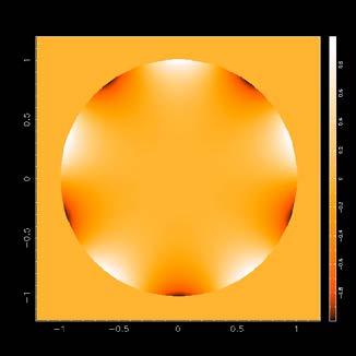
77 Thermal Distortions due to Solar Heating Time Second Sardinian Summer School on Single-Dish Radio Astronomy and Radio Science 77

78 Example Daytime AutoOOF Correction Second Sardinian Summer School on Single-Dish Radio Astronomy and Radio Science 78
79 How Long is it Good For? About 2 hours But probably depends on many factors including observing mode: Tracking a single source All-sky survey, etc. 3 Scans on OOF 25 min old (3C273) OOF 90 min old (J ) OOF 200 min old (J ) Second Sardinian Summer School on Single-Dish Radio Astronomy and Radio Science 79
80 Estimated error budget Small-scale errors: panel manufacturing plus gravity error: 127 µm residual actuator error: 80 µm panel corner setting error: 80 µm panel-scale thermal errors: 100 µm subreflector: 75 µm total small-scale error: = 211 µm Large-scale thermal error: 100 µm Total error: = 235 µm 80
81 Acknowledgements Bojan Nikolic (OOF holography) Todd Hunter, Fred Schwab, Steve White (with-phase holography) GBT Engineering Staff (temperature sensors, inclinometers ) Second Sardinian Summer School on Single-Dish Radio Astronomy and Radio Science 81
Performance and Properties of the GBT
 Performance and Properties of the GBT Richard Prestage for the PTCS Team GBT High Frequency Science Workshop 21 September 2015 Atacama Large Millimeter/submillimeter Array Karl G. Jansky Very Large Array
Green Bank Telescope Performance
 Green Bank Telescope Performance Dana S. Balser GBT Performance July 2007 Pune, NCRA Telescope Structure Unblocked Aperture Frequency Coverage Telescope Control Focus Surface Pointing Pointing Requirements
Out-Of-Focus Holography at the Green Bank Telescope
 Astronomy & Astrophysics manuscript no. gbtoofpaper January 2, 27 (DOI: will be inserted by hand later) Out-Of-Focus Holography at the Green Bank Telescope B. Nikolic,2, R. M. Prestage, D. S. Balser, C.
How to improve the high-frequency capabilities of the SRT
 Mem. S.A.It. Suppl. Vol. 10, 136 c SAIt 2006 Memorie della Supplementi How to improve the high-frequency capabilities of the SRT T. Pisanu 1, F. Buffa 2, M. Morsiani 3, M. Natalini 1, C. Pernechele 2,
The GBT Precision Telescope Control System. Kim Constantikes
 The GBT Precision Telescope Control System Kim Constantikes Ohio University May 24, 2004 Overview The Green Bank Telescope Scientific Requirements and Objectives The Real Telescope Instrumentation Next
Background, theory and practical limitations of metrology systems at Radio Astronomy Antennas
 Metrology Systems for Radio Astronomy at MTM Background, theory and practical limitations of metrology systems at Radio Astronomy Antennas Chalmers University of Technology, Gothenburg, Sweden September
Metrology and Control of Large Telescopes
 T. Pisanu tpisanu@oa-cagliari.inaf.it on behalf of Metrology team* *G. Serra, S. Poppi, F. Buffa, P. Marongiu, R. Concu, G. Vargiu, P. Ortu, A. Saba, E.Urru, G. Deiana Astronomical Observatory of Cagliari
x Contents Segmented Mirror Telescopes Metal and Lightweight Mirrors Mirror Polishing
 Contents 1 Fundamentals of Optical Telescopes... 1 1.1 A Brief History of Optical Telescopes.................... 1 1.2 General Astronomical Requirements..................... 6 1.2.1 Angular Resolution.............................
The Principles of Astronomical Telescope Design
 The Principles of Astronomical Telescope Design Jingquan Cheng National Radio Astronomy Observatory Charlottesville, Virginia,.USA " 4y Springer Fundamentals of Optical Telescopes 1 1.1 A Brief History
Millimeter Antenna Calibration
 Millimeter Antenna Calibration 9 th IRAM Millimeter Interferometry School 10-14 October 2016 Michael Bremer, IRAM Grenoble The beam (or: where does an antenna look?) How and where to build a mm telescope
Continuum Observing. Continuum Emission and Single Dishes
 July 11, 2005 NAIC/NRAO Single-dish Summer School Continuum Observing Jim Condon Continuum Emission and Single Dishes Continuum sources produce steady, broadband noise So do receiver noise and drift, atmospheric
In-Flight Retrieval of Reflector Anomalies for the Planck Space Telescope
 Presented at The 4 th European Conference on Antennas and Propagation (EuCAP 2010), Barcelona, Spain, 12-16 April 2010. In-Flight Retrieval of Reflector Anomalies for the Planck Space Telescope Frank Jensen*,
Commissioning of the Hanle Autoguider
 Commissioning of the Hanle Autoguider Copenhagen University Observatory Edited November 10, 2005 Figure 1: First light image for the Hanle autoguider, obtained on September 17, 2005. A 5 second exposure
Beam Scan Properties of Nonparabolic Reflectors. P.J. N a p ie r National Radio Astronomy Observatory, Socorro, New Mexico 87801
 NLSRT Memo No.. / / ' /ft Beam Scan Properties of Nonparabolic Reflectors P.J. N a p ie r National Radio Astronomy Observatory, Socorro, New Mexico 87801 Abstract. Nonparabolic reflector systems such as
Submillimeter Array Technical Memorandum
 Submillimeter Array Technical Memorandum Number: 5 Date: August 2, 99 From: Cohn Masson Antenna Surface Measurement for the SMA Summary I discuss the available techniques for measuring the surface of the
Pointing calibration campaign at 21 GHz with K-band multi-feed receiver
 Pointing calibration campaign at 1 GHz with K-band multi-feed receiver R.Verma, L.Gregorini, I.Prandoni, A.Orfei IRA 1/11 February 17, 11 Contents 1 Pointing Model 5 1.1 Primary pointing equations...............................
Phase-Referencing and the Atmosphere
 Phase-Referencing and the Atmosphere Francoise Delplancke Outline: Basic principle of phase-referencing Atmospheric / astrophysical limitations Phase-referencing requirements: Practical problems: dispersion
Atmospheric phase correction for ALMA with water-vapour radiometers
 Atmospheric phase correction for ALMA with water-vapour radiometers B. Nikolic Cavendish Laboratory, University of Cambridge January 29 NA URSI, Boulder, CO B. Nikolic (University of Cambridge) WVR phase
RF properties. of the Planck telescope. Designed by ALCATEL. CASE No. 1. Per Heighwood Nielsen
 TICRA engineering consultants communications systems and antennas RF properties of the Planck telescope Designed by ALCATEL CASE No. 1 November, 1999 S-801-04 Author: Per Heighwood Nielsen TICRA KRON PRINSENS
Thermal Behavior of the Leighton 10-m Antenna Backing Structure
 MMA Memo. 3 Thermal Behavior of the Leighton -m Antenna Backing Structure James W Lamb and David P Woody Owens Valley Radio Observatory California Institute of Technology 3 October, 99 Abstract: One of
Control of the Keck and CELT Telescopes. Douglas G. MacMartin Control & Dynamical Systems California Institute of Technology
 Control of the Keck and CELT Telescopes Douglas G. MacMartin Control & Dynamical Systems California Institute of Technology Telescope Control Problems Light from star Primary mirror active control system
Memo 106 Composite Applications for Radio Telescopes (CART): The Mk2 Reflector Results.
: The Mk2 Reflector Results.") Memo 106 Composite Applications for Radio Telescopes (CART): The Mk2 Reflector Results. D. Chalmers G. Lacy 01/09 www.skatelescope.org/pages/page_memos.htm 1 SKA Memo 106 Composite Applications for Radio
Memo 106 Composite Applications for Radio Telescopes (CART): The Mk2 Reflector Results. D. Chalmers G. Lacy 01/09 www.skatelescope.org/pages/page_memos.htm 1 SKA Memo 106 Composite Applications for Radio
Holography at the ATA
 ATA Memo #65 Holography at the ATA G. R. Harp and R. F. Ackermann 3/21/4 Abstract Beam patterns acquired from the offset Gregorian ATA dishes using prototype ATA feeds (electrically equivalent to final
NATIONAL RADIO ASTRONOMY OBSERVATORY MEMORANDUM
 NATIONAL RADIO ASTRONOMY OBSERVATORY MEMORANDUM DATE: September 16, 1996 TO: M. Clark, B. Garwood, D. Hogg, H. Liszt FROM: Ron Maddalena SUBJECT: GBT and Aips++ requirements for traditional, all-sky pointing
Primary Mirror Cell Deformation and Its Effect on Mirror Figure Assuming a Six-zone Axial Defining System
 Primary Mirror Cell Deformation and Its Effect on Mirror Figure Larry Stepp Eugene Huang Eric Hansen Optics Manager Opto-structural Engineer Opto-mechanical Engineer November 1993 GEMINI PROJECT OFFICE
The Robert C. Byrd Green Bank Telescope
 The Robert C. Byrd Green Bank Telescope Phil Jewell National Radio Astronomy Observatory 520 Edgemont Road Charlottesville, VA 22903-2475 USA pjewell@nrao.edu NAIC-NRAO School on Single Dish Radio Astronomy
AOL Spring Wavefront Sensing. Figure 1: Principle of operation of the Shack-Hartmann wavefront sensor
 AOL Spring Wavefront Sensing The Shack Hartmann Wavefront Sensor system provides accurate, high-speed measurements of the wavefront shape and intensity distribution of beams by analyzing the location and
Response of DIMM turbulence sensor
 Response of DIMM turbulence sensor A. Tokovinin Version 1. December 20, 2006 [tdimm/doc/dimmsensor.tex] 1 Introduction Differential Image Motion Monitor (DIMM) is an instrument destined to measure optical
Opto-Mechanical I/F for ANSYS
 Opto-Mechanical I/F for ANSYS Victor Genberg, Gregory Michels, Keith Doyle Sigmadyne, Inc. Abstract Thermal and structural output from ANSYS is not in a form useful for optical analysis software. Temperatures,
Optical/IR Observational Astronomy Telescopes I: Optical Principles. David Buckley, SAAO. 24 Feb 2012 NASSP OT1: Telescopes I-1
 David Buckley, SAAO 24 Feb 2012 NASSP OT1: Telescopes I-1 1 What Do Telescopes Do? They collect light They form images of distant objects The images are analyzed by instruments The human eye Photographic
Advanced Topic in Astrophysics Lecture 1 Radio Astronomy - Antennas & Imaging
 Advanced Topic in Astrophysics Lecture 1 Radio Astronomy - Antennas & Imaging Course Structure Modules Module 1, lectures 1-6 (Lister Staveley-Smith, Richard Dodson, Maria Rioja) Mon Wed Fri 1pm weeks
Pupil matching of Zernike aberrations
 Pupil matching of Zernike aberrations C. E. Leroux, A. Tzschachmann, and J. C. Dainty Applied Optics Group, School of Physics, National University of Ireland, Galway charleleroux@yahoo.fr Abstract: The
CHARA Meeting 2017 Pasadena, California
 MORE AUTOMATION Laszlo Sturmann M7 ACTUATORS LAB. LASER ALIGNMENT TELESCOPE OPTICAL ALIGNMENT NEW ACTUATORS REMOTELY ACTUATED M7 MOUNT MOTIVATION THE PRECISION OF THE COUDE ALIGNMENT WAS NOT SUFFICIENT
Optical Interface for MSC.Nastran
 Optical Interface for MSC.Nastran Victor Genberg, Keith Doyle, Gregory Michels Sigmadyne, Inc., 803 West Ave, Rochester, NY 14611 genberg@sigmadyne.com Abstract Thermal and structural output from MSC.Nastran
Analysis on the track unevenness and alidade temperature behavior of TM65m antenna
 Analysis on the track unevenness and alidade temperature behavior of TM65m antenna Li Fu, Quan-bao Ling, Rong-bing Zhao, Jinqing Wang, Xu-guang Geng, Yong-bin Jiang, Lin-feng Yu, Wei Gou 20 th September,2016
The Distributed Defining System for the Primary Mirrors
 The Distributed Defining System for the Primary Mirrors Larry Stepp Myung K. Cho Optics Manager Opto-structural Engineer November 5, 1993 GEMINI PROJECT OFFICE 950 N. Cherry Ave. Tucson, Arizona 85719
1 Naval Research Laboratory Remote Sensing Division, Code Aberdeen Ave SE Kirtland AFB, NM 87117
 Carbon Fiber Reinforced Polymer (CFRP) Telescope Program at the Naval Research Laboratory Sergio R. Restaino 1, Ty Martinez 1, Jonathan R. Andrews 1, Christopher C. Wilcox 1, S. Teare 2, Robert Romeo 3,
Submillimetre astronomy
 Sep. 20 2012 Spectral line submillimetre observations Observations in the submillimetre wavelengths are in principle not different from those made at millimetre wavelengths. There are however, three significant
1 General Considerations: Point Source Sensitivity, Surface Brightness Sensitivity, and Photometry
 MUSTANG Sensitivities and MUSTANG-1.5 and - Sensitivity Projections Brian S. Mason (NRAO) - 6sep1 This technical note explains the current MUSTANG sensitivity and how it is calculated. The MUSTANG-1.5
Radio Astronomy An Introduction
 Radio Astronomy An Introduction Felix James Jay Lockman NRAO Green Bank, WV References Thompson, Moran & Swenson Kraus (1966) Christiansen & Hogbom (1969) Condon & Ransom (nrao.edu) Single Dish School
ALMA Memo 373 Relative Pointing Sensitivity at 30 and 90 GHz for the ALMA Test Interferometer M.A. Holdaway and Jeff Mangum National Radio Astronomy O
 ALMA Memo 373 Relative Pointing Sensitivity at 30 and 90 GHz for the ALMA Test Interferometer M.A. Holdaway and Jeff Mangum National Radio Astronomy Observatory 949 N. Cherry Ave. Tucson, AZ 85721-0655
Measurements of the DL0SHF 8 GHz Antenna
 Measurements of the DL0SHF 8 GHz Antenna Joachim Köppen, DF3GJ Inst.Theoret.Physik u.astrophysik, Univ. Kiel September 2015 Pointing Correction Position errors had already been determined on a few days
Deconvolving Primary Beam Patterns from SKA Images
 SKA memo 103, 14 aug 2008 Deconvolving Primary Beam Patterns from SKA Images Melvyn Wright & Stuartt Corder University of California, Berkeley, & Caltech, Pasadena, CA. ABSTRACT In this memo we present
Astronomy. Optics and Telescopes
 Astronomy A. Dayle Hancock adhancock@wm.edu Small 239 Office hours: MTWR 10-11am Optics and Telescopes - Refraction, lenses and refracting telescopes - Mirrors and reflecting telescopes - Diffraction limit,
SOFIA Telescope Manufacturing - Lessons Learned
 SOFIA Telescope Manufacturing - Lessons Learned Hans J. Kaercher, Senior Telescope Engineer MT Mechatronics GmbH, Mainz, Germany hans.kaercher@mt-mechatronics.de 1 Experience with Telescopes at Exposed
Optical interferometry: problems and practice
 Outline Optical interferometry: problems and practice Chris Haniff Aims. What is an interferometer? Fundamental differences between optical and radio. Implementation at optical wavelengths. Conclusions.
Astronomical Tools. Optics Telescope Design Optical Telescopes Radio Telescopes Infrared Telescopes X Ray Telescopes Gamma Ray Telescopes
 Astronomical Tools Optics Telescope Design Optical Telescopes Radio Telescopes Infrared Telescopes X Ray Telescopes Gamma Ray Telescopes Laws of Refraction and Reflection Law of Refraction n 1 sin θ 1
Part I. The Quad-Ridged Flared Horn
 9 Part I The Quad-Ridged Flared Horn 10 Chapter 2 Key Requirements of Radio Telescope Feeds Almost all of today s radio telescopes operating above 0.5 GHz use reflector antennas consisting of one or more
On the possibility to create a prototype of laser system for space debris movement control on the basis of the 3-meter telescope.
 OJC «RPC «Precision Systems and Instruments», Moscow, Russia A. Alexandrov, V. Shargorodskiy On the possibility to create a prototype of laser system for space debris movement control on the basis of the
Sky demonstration of potential for ground layer adaptive optics correction
 Sky demonstration of potential for ground layer adaptive optics correction Christoph J. Baranec, Michael Lloyd-Hart, Johanan L. Codona, N. Mark Milton Center for Astronomical Adaptive Optics, Steward Observatory,
Radio Astronomy with a Satellite Dish
 Radio Astronomy with a Satellite Dish Michael Gaylard Hartebeesthoek Radio Astronomy Observatory September 13, 2012 1 Theory 1.1 Radio Waves Radio waves are electromagnetic waves having wavelengths greater
Astronomy 203 practice final examination
 Astronomy 203 practice final examination Fall 1999 If this were a real, in-class examination, you would be reminded here of the exam rules, which are as follows: You may consult only one page of formulas
Daily Alignment Procedure with 2 AO Wave Front Sensors
 Daily Alignment Procedure with 2 AO Wave Front Sensors First Version Judit Sturmann Talk Outline AO at CHARA design scheme Before sky alignment Keeping the alignment during the night Lab and Telescope
Telescopes and Optical Systems
 Telescopes and Optical Systems Goals of a telescope: To collect as much light as possible To bring the light to as sharp a focus as possible Numbers to keep in mind: ~ 206,265 arcsec in a radian 1.22 =
Expected Performance From WIYN Tip-Tilt Imaging
 Expected Performance From WIYN Tip-Tilt Imaging C. F. Claver 3 September 1997 Overview Image motion studies done at WIYN show that a significant improvement to delivered image quality can be obtained from
Development of surface metrology for the Giant Magellan Telescope primary mirror
 Development of surface metrology for the Giant Magellan Telescope primary mirror J. H. Burge a,b, W. Davison a, H. M. Martin a, C. Zhao b a Steward Observatory, University of Arizona, Tucson, AZ 85721,
Galactic Structure Mapping through 21cm Hyperfine Transition Line
 Galactic Structure Mapping through 21cm Hyperfine Transition Line Henry Shackleton MIT Department of Physics (Dated: May 14, 2017) Using a Small Radio Telescope (SRT), we measure electromagnetic radiation
Single dish radio telescopes!
 NRO-ALMA Science/Development Workshop 2015 Nobeyama, 28-30 July 2025 Single dish radio telescopes Is there a need to grow? Is there a limit to growth? Development of (sub)-millimeter telescopes Jacob W.M.
McMath-Pierce Adaptive Optics Overview. Christoph Keller National Solar Observatory, Tucson
 McMath-Pierce Adaptive Optics Overview Christoph Keller National Solar Observatory, Tucson Small-Scale Structures on the Sun 1 arcsec Important astrophysical scales (pressure scale height in photosphere,
High (Angular) Resolution Astronomy
 Resolution Astronomy") High (Angular) Resolution Astronomy http://www.mrao.cam.ac.uk/ bn204/ mailto:b.nikolic@mrao.cam.ac.uk Astrophysics Group, Cavendish Laboratory, University of Cambridge January 2012 Outline Science Drivers
High (Angular) Resolution Astronomy http://www.mrao.cam.ac.uk/ bn204/ mailto:b.nikolic@mrao.cam.ac.uk Astrophysics Group, Cavendish Laboratory, University of Cambridge January 2012 Outline Science Drivers
Analysis of the NOT Primary Mirror Dynamics
 Analysis of the NOT Primary Mirror Dynamics Graham C. Cox October 24, 2000 Introduction On the nights of 12th and 13th May 2000 observations were made using the JOSE camera system, borrowed from the ING,
Fundamental Limits to Wavefront Sensing in the Submillimeter
 Fundamental Limits to Wavefront Sensing in the Submillimeter E. Serabyn Jet Propulsion Laboratory, California Institute of Technology, 4800 Oak Grove Drive, Pasadena, CA, USA 91109 Copyright 2006 Society
Astronomical Experiments for the Chang E-2 Project
 Astronomical Experiments for the Chang E-2 Project Maohai Huang 1, Xiaojun Jiang 1, and Yihua Yan 1 1 National Astronomical Observatories, Chinese Academy of Sciences, 20A Datun Road,Chaoyang District,
More Optical Telescopes
 More Optical Telescopes There are some standard reflecting telescope designs used today All have the common feature of light entering a tube and hitting a primary mirror, from which light is reflected
Magnifying Glass. Angular magnification (m): 25 cm/f < m < 25cm/f + 1. image at 25 cm (= normal near point) relaxed eye, image at (normal) far point
: 25 cm/f < m < 25cm/f + 1. image at 25 cm (= normal near point) relaxed eye, image at (normal) far point") Magnifying Glass Angular magnification (m): 25 cm/f < m < 25cm/f + 1 relaxed eye, image at (normal) far point image at 25 cm (= normal near point) For more magnification, first use a lens to form an enlarged
Magnifying Glass Angular magnification (m): 25 cm/f < m < 25cm/f + 1 relaxed eye, image at (normal) far point image at 25 cm (= normal near point) For more magnification, first use a lens to form an enlarged
PAPER 338 OPTICAL AND INFRARED ASTRONOMICAL TELESCOPES AND INSTRUMENTS
 MATHEMATICAL TRIPOS Part III Monday, 12 June, 2017 1:30 pm to 3:30 pm PAPER 338 OPTICAL AND INFRARED ASTRONOMICAL TELESCOPES AND INSTRUMENTS Attempt no more than TWO questions. There are THREE questions
IMPROVING BEAM QUALITY NEW TELESCOPE ALIGNMENT PROCEDURE
 IMPROVING BEAM QUALITY NEW TELESCOPE ALIGNMENT PROCEDURE by Laszlo Sturmann Fiber coupled combiners and visual band observations are more sensitive to telescope alignment problems than bulk combiners in
Single-dish antenna at (sub)mm wavelengths
mm wavelengths") Single-dish antenna at (sub)mm wavelengths P. Hily-Blant Institut de Planétologie et d Astrophysique de Grenoble Université Joseph Fourier October 15, 2012 Introduction A single-dish antenna Spectral surveys
Single-dish antenna at (sub)mm wavelengths P. Hily-Blant Institut de Planétologie et d Astrophysique de Grenoble Université Joseph Fourier October 15, 2012 Introduction A single-dish antenna Spectral surveys
Speckles and adaptive optics
 Chapter 9 Speckles and adaptive optics A better understanding of the atmospheric seeing and the properties of speckles is important for finding techniques to reduce the disturbing effects or to correct
Introduction to Interferometry
 Introduction to Interferometry Ciro Pappalardo RadioNet has received funding from the European Union s Horizon 2020 research and innovation programme under grant agreement No 730562 Radioastronomy H.Hertz
Thermal and Wind Effects on the Azimuth Axis Tilt of the ASTE 10-m Antenna
 Publ. Natl. Astron. Obs. Japan Vol. 10. 25 33 (2007) Thermal and Wind Effects on the Azimuth Axis Tilt of the ASTE 10-m Antenna Nobuharu UKITA, Hajime EZAWA, Bungo IKENOUE, and Masao SAITO (Receved April
Error Budgets, and Introduction to Class Projects. Lecture 6, ASTR 289
 Error Budgets, and Introduction to Class Projects Lecture 6, ASTR 89 Claire Max UC Santa Cruz January 8, 016 Page 1 What is residual wavefront error? Telescope AO System Science Instrument Very distorted
Satellite and debris characterisation in LEO and GEO using adaptive optics
 Satellite and debris characterisation in LEO and GEO using adaptive optics M. Copeland, F. Bennet, F. Rigaut, C. d Orgeville and V. Korkiakoski Research School of Astronomy and Astrophysics, Australian
The Secret Behind the Nobeyama 45-m Radio Telescope s Excellent
 The Secret Behind the Nobeyama 45-m Radio Telescope s Excellent Even now over 30 years after its completion in 1982, the 45 m diameter radio telescope at NAOJ s Nobeyama Radio Observatory boasts world
International Journal of Scientific & Engineering Research, Volume 4, Issue 7, July ISSN
 International Journal of Scientific & Engineering Research, Volume 4, Issue 7, July-2013 96 Performance and Evaluation of Interferometric based Wavefront Sensors M.Mohamed Ismail1, M.Mohamed Sathik2 Research
A beam of coherent monochromatic light from a distant galaxy is used in an optics experiment on Earth.
 Waves_P2 [152 marks] A beam of coherent monochromatic light from a distant galaxy is used in an optics experiment on Earth. The beam is incident normally on a double slit. The distance between the slits
ALMA Memo No. 345 Phase Fluctuation at the ALMA site and the Height of the Turbulent Layer January 24, 2001 Abstract Phase compensation schemes are ne
 Yasmin Robson Mullard Radio Astronomy Observatory, Cavendish Laboratory, Cambridge CB3 OHE, UK yr@astro.ox.ac.uk Richard Hills Mullard Radio Astronomy Observatory, Cavendish Laboratory, Cambridge CB3 OHE,
PhysicsAndMathsTutor.com 1
 PhysicsAndMathsTutor.com 1 1. The diagram shows the concave mirror of a Cassegrain reflecting telescope, together with the eyepiece lens. Complete the diagram of the telescope and mark on it the focal
Interference Problems at the Effelsberg 100-m Telescope
 Interference Problems at the Effelsberg 100-m Telescope Wolfgang Reich Max-Planck-Institut für Radioastronomie, Bonn Abstract: We summarise the effect of interference on sensitive radio continuum and polarisation
Solar System Objects. Bryan Butler National Radio Astronomy Observatory
 Solar System Objects Bryan Butler National Radio Astronomy Observatory Atacama Large Millimeter/submillimeter Array Expanded Very Large Array Robert C. Byrd Green Bank Telescope Very Long Baseline Array
Jin Huang,Jie Zhang. Key Laboratory of Electronic Equipment Structure Design Ministry of Education, Xidian University. Sept.
 电子装备结构设计 Metrology and Control of Large Telescopes workshop, 2016, Green Bank, US 教育部重点实验室 Wind Effect and its Compensation for Large Reflector Antennas Jin Huang,Jie Zhang Key Laboratory of Electronic
Telescope Project Development Seminar
 Telescope Project Development Seminar Session 4: Telescope Performance Matt Johns 4/19/2017 U. Tokyo 4/9/2017 Telescope Project Development 1 Session Outline GMT imaging Image Size Atmospheric dispersion
CHARA Collaboration Year-Eight Science Review. VLTI update. F. Delplancke
 VLTI update F. Delplancke Summary Infrastructure Current instruments: MIDI, AMBER, PIONIER Under test & commissioning: PRIMA 2 nd generation instruments Long Range Plan Infrastructure Infrastructure 4
The Green Bank Telescope: an Overview
 The Green Bank Telescope: an Overview Felix J. Lockman a Library National Radio Astronomy Observatory, P.O. Box 2, Green Bank, WV USA ABSTRACT The Green Bank Telescope, now under construction at the National
Lecture Outlines. Chapter 5. Astronomy Today 8th Edition Chaisson/McMillan Pearson Education, Inc.
 Lecture Outlines Chapter 5 Astronomy Today 8th Edition Chaisson/McMillan Chapter 5 Telescopes Units of Chapter 5 5.1 Optical Telescopes 5.2 Telescope Size 5.3 Images and Detectors 5.4 High-Resolution Astronomy
IMPLEMENTATION OF A QUASI-OPTICAL FREE-SPACE S-PARAMETERS MEASUREMENT SYSTEM
 IMPLEMENTATION OF A QUASI-OPTICAL FREE-SPACE S-PARAMETERS MEASUREMENT SYSTEM B. Maffei, S. Legg, M. Robinson, F. Ozturk, M. W. Ng, P. Schemmel and G. Pisano. JBCA, School of Physics and Astronomy, The
7. Telescopes: Portals of Discovery Pearson Education Inc., publishing as Addison Wesley
 7. Telescopes: Portals of Discovery Parts of the Human Eye pupil allows light to enter the eye lens focuses light to create an image retina detects the light and generates signals which are sent to the
How do you make an image of an object?
 How do you make an image of an object? Use a camera to take a picture! But what if the object is hidden?...or invisible to the human eye?...or too far away to see enough detail? Build instruments that
1 o.3. 0 o.5. Dec. 1 o.0 R.A. on 0. o 5 off 1. o 0 1. o
 An Optical Reector System for the CANGAROO-II Telescope Akiko Kawachi for the CANGAROO Collaboration 1 Institute for Cosmic Ray Research, University of Tokyo Tanashi, Tokyo 188-8502, Japan 2 Abstract.
Outline. Mm-Wave Interferometry. Why do we care about mm/submm? Star-forming galaxies in the early universe. Dust emission in our Galaxy
 Outline 2 Mm-Wave Interferometry Debra Shepherd & Claire Chandler Why a special lecture on mm interferometry? Everything about interferometry is more difficult at high frequencies Some problems are unique
Disturbance Feedforward Control for Vibration Suppression in Adaptive Optics of Large Telescopes
 Disturbance Feedforward Control for Vibration Suppression in Adaptive Optics of Large Telescopes Martin Glück, Jörg-Uwe Pott, Oliver Sawodny Reaching the Diffraction Limit of Large Telescopes using Adaptive
So far, we have considered three basic classes of antennas electrically small, resonant
 Unit 5 Aperture Antennas So far, we have considered three basic classes of antennas electrically small, resonant (narrowband) and broadband (the travelling wave antenna). There are amny other types of
Integrating MD Nastran with Optical Performance Analysis
 Integrating MD Nastran with Optical Performance Analysis Victor Genberg, Gregory Michels Sigmadyne, Inc., 803 West Ave, Rochester, NY 14611 genberg@sigmadyne.com Abstract The development of products in
Temperature Scales and Telescope Efficiencies
 Temperature Scales and Telescope Efficiencies Jeff Mangum (NRAO) April 11, 2006 Contents 1 Introduction 1 2 Definitions 1 2.1 General Terms.................................. 2 2.2 Efficiencies....................................
1
 Daniel.Schuetze@aei.mpg.de 1 Satellite gravimetry Mapping the global gravity field Static and dynamic components Many applications in geosciences Techniques Orbit determination and tracking Satellite-to-satellite
Development of a solar imaging array of Very Small Radio Telescopes
 Development of a solar imaging array of Very Small Radio Telescopes Ted Tsiligaridis University of Washington, Seattle Mentor: Alan E.E. Rogers MIT Haystack Observatory Summer 27 Outline 1. Solar Physics
Control of the Laser Interferometer Space Antenna
 Control of the Laser Interferometer Space Antenna P. G. Maghami, T. T. Hyde NASA Goddard Space Flight Center Guidance, Navigation and Control Division Greenbelt, MD 20771 J. Kim Swales Aerospace, Inc.
April 30, 1998 What is the Expected Sensitivity of the SMA? SMA Memo #125 David Wilner ABSTRACT We estimate the SMA sensitivity at 230, 345 and 650 GH
 April 30, 1998 What is the Expected Sensitivity of the SMA? SMA Memo #125 David Wilner ABSTRACT We estimate the SMA sensitivity at 230, 345 and 650 GHz employing current expectations for the receivers,
What do companies win being a supplier to ESO
 What do companies win being a supplier to ESO Arnout Tromp Head of Contracts and Procurement Topics Characteristics of what ESO procures Technology in Astronomy Spin off from the past The future: E-ELT
Unstable optical resonators. Laser Physics course SK3410 Aleksandrs Marinins KTH ICT OFO
 Unstable optical resonators Laser Physics course SK3410 Aleksandrs Marinins KTH ICT OFO Outline Types of resonators Geometrical description Mode analysis Experimental results Other designs of unstable