Control System Design
|
|
|
- Suzan West
- 5 years ago
- Views:
Transcription
1 ELEC ENG 4CL4: Control System Design Notes for Lecture #15 Friday, February 6, 2004 Dr. Ian C. Bruce Room: CRL-229 Phone ext.:
2 (3) Cohen-Coon Reaction Curve Method Cohen and Coon carried out further studies to find controller settings which, based on the same model, lead to a weaker dependence on the ratio of delay to time constant. Their suggested controller settings are shown in Table 6.3: P PI PID K p T r T d [ ν o 1+ τ ] o K o τ o [ 3ν o ν o 0.9+ τ ] o τ o [30ν o +3τ o ] K o τ o [ 12ν o 9ν o +20τ o ν o 4 K o τ o 3 + τ ] o τ o [32ν o +6τ o ] 4τ o ν o 4ν o 13ν o +8τ o 11ν o +2τ o Table 6.3: Cohen-Coon tuning using the reaction curve.
3 General System Revisited Consider again the general plant: G K ( ) 0e sτ 0 s = γ0s + 1 The next slide shows the closed loop responses resulting from Cohen-Coon Reaction Curve tuning for different values of x =. ν τ 0
4 Figure 6.8: PI Cohen-Coon tuned (reaction curve method) control loop 2 Cohen Coon (reaction curve) for different values of the ratio x= τ/ν o x=0.1 Plant response x= Time [t/τ]
5 Lead-lag Compensators Closely related to PID control is the idea of lead-lag compensation. The transfer function of these compensators is of the form: C(s) = τ 1s +1 τ 2 s +1 If τ 1 > τ 2, then this is a lead network and when τ 1 < τ 2, this is a lag network.
6 Figure 6.9: Approximate Bode diagrams for lead networks (τ 1 =10τ 2 ) C db 20[dB] C(jω) ω π τ 1 1 τ τ 2 τ 2 ω
7 Observation We see from the previous slide that the lead network gives phase advance at ω = 1/τ 1 without an increase in gain. Thus it plays a role similar to derivative action in PID.
8 Application of lead compensator to increase phase stability margin Say we have a control loop with a very small phase margin at frequency ω 1. The lead compensator gives approximately 45 of phase lead at ω = 1/τ 1, without a significant change in gain. If we insert a lead compensator with τ 1 = 1/ω 1 into our control loop, we will increase the phase margin by close to 45.
9 Nyquist stability plot for control loop without lead compensation 2 Nyquist Diagram Imaginary Axis o Real Axis
10 Bode plot of lead compensator 20 Bode Diagram Phase (deg) Magnitude (db) Frequency (rad/sec)
11 Nyquist stability plot for control loop with lead compensation 2 Nyquist Diagram Imaginary Axis o Real Axis
12 Figure 6.10: Approximate Bode diagrams for lag networks (τ 2 =10τ 1 ) C db τ 2 τ 1 τ 2 τ 1 ω 20[dB] C(jω) ω π 4
13 Observation We see from the previous slide that the lag network gives low frequency gain increase. Thus it plays a role similar to integral action in PID.
14 Illustrative Case Study: Distillation Column PID control is very widely used in industry. Indeed, one would we hard pressed to find loops that do not use some variant of this form of control. Here we illustrate how PID controllers can be utilized in a practical setting by briefly examining the problem of controlling a distillation column.
15 Example System The specific system we study here is a pilot scale ethanol-water distillation column. Photos of the column (which is in the Department of Chemical Engineering at the University of Sydney, Australia) are shown on the next slide.
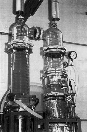
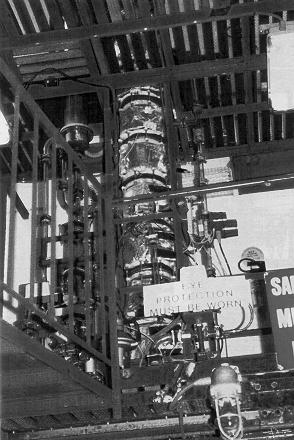
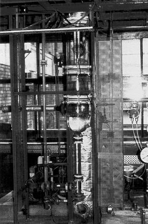
16 Condenser Feed-point Reboiler
17 Figure 6.11: Ethanol - water distillation column A schematic diagram of the column is given below:
18 Model A locally linearized model for this system is as follows: where [ ] Y1 (s) Y 2 (s) = [ ][ ] G11 (s) G 12 (s) U1 (s) G 21 (s) G 22 (s) U 2 (s) G 11 (s) = 0.66e 2.6s 6.7s +1 G 12 (s) = e s 9.06s +1 G 21 (s) = 34.7e 9.2s 8.15s (11.6s +1)e s G 22 (s) = (3.89s + 1)(18.8s +1) Note that the units of time here are minutes.
19 Decentralized PID Design We will use two PID controllers: One connecting Y 1 to U 1 The other, connecting Y 2 to U 2.
20 In designing the two PID controllers we will initially ignore the two transfer functions G 12 and G 21. This leads to two separate (and non-interacting) SISO systems. The resultant controllers are: C 1 (s) = s C s (s) = s We see that these are of PI type.
21 Simulations We simulate the performance of the system with the two decentralized PID controllers. A two unit step in reference 1 is applied at time t = 50 and a one unit step is applied in reference 2 at time t = 250. The system was simulated with the true coupling (i.e. including G 12 and G 21 ). The results are shown on the next slide.
22 Figure 6.12:Simulation results for PI control of distillation column Plant outputs & ref r 1 (t) y 1 (t) r 2 (t) y 2 (t) Time [minutes] It can be seen from the figure that the PID controllers give quite acceptable performance on this problem. However, the figure also shows something that is very common in practical applications - namely the two loops interact i.e. a change in reference r 1 not only causes a change in y 1 (as required) but also induces a transient in y 2. Similarly a change in the reference r 2 causes a change in y 2 (as required) and also induces a change in y 1. In this particular example, these interactions are probably sufficiently small to be acceptable. Thus, in common with the majority of industrial problems, we have found that two simple PID (actually PI in this case) controllers give quite acceptable performance for this problem. Later we will see how to design a full multivariable controller for this problem that accounts for the interaction.
23 Summary PI and PID controllers are widely used in industrial control. From a modern perspective, a PID controller is simply a controller of (up to second order) containing an integrator. Historically, however, PID controllers were tuned in terms of their P, I and D terms. It has been empirically found that the PID structure often has sufficient flexibility to yield excellent results in many applications.
24 The basic term is the proportional term, P, which causes a corrective control actuation proportional to the error. The integral term, I gives a correction proportional to the integral of the error. This has the positive feature of ultimately ensuring that sufficient control effort is applied to reduce the tracking error to zero. However, integral action tends to have a destabilizing effect due to the increased phase shift.
25 The derivative term, D, gives a predictive capability yielding a control action proportional to the rate of change of the error. This tends to have a stabilizing effect but often leads to large control movements. Various empirical tuning methods can be used to determine the PID parameters for a given application. They should be considered as a first guess in a search procedure.
26 Attention should also be paid to the PID structure. Systematic model-based procedures for PID controllers will be covered in later chapters. A controller structure that is closely related to PID is a lead-lag network. The lead component acts like D and the lag acts like I.
Control System Design
 ELEC ENG 4CL4: Control System Design Notes for Lecture #13 Monday, February 3, 2003 Dr. Ian C. Bruce Room: CRL-229 Phone ext.: 26984 Email: ibruce@mail.ece.mcmaster.ca (3) Cohen-Coon Reaction Curve Method
Control System Design
 ELEC ENG 4CL4: Control System Design Notes for Lecture #11 Wednesday, January 28, 2004 Dr. Ian C. Bruce Room: CRL-229 Phone ext.: 26984 Email: ibruce@mail.ece.mcmaster.ca Relative Stability: Stability
Control System Design
 ELEC ENG 4CL4: Control System Design Notes for Lecture #14 Wednesday, February 5, 2003 Dr. Ian C. Bruce Room: CRL-229 Phone ext.: 26984 Email: ibruce@mail.ece.mcmaster.ca Chapter 7 Synthesis of SISO Controllers
Control System Design
 ELEC ENG 4CL4: Control System Design Notes for Lecture #19 Monday, February 24, 2003 Dr. Ian C. Bruce Room: CRL-229 Phone ext.: 26984 Email: ibruce@mail.ece.mcmaster.ca An Industrial Application (Hold-
Control System Design
 ELEC ENG 4CL4: Control System Design Notes for Lecture #22 Dr. Ian C. Bruce Room: CRL-229 Phone ext.: 26984 Email: ibruce@mail.ece.mcmaster.ca Friday, March 5, 24 More General Effects of Open Loop Poles
Control System Design
 ELEC ENG 4CL4: Control System Design Notes for Lecture #36 Dr. Ian C. Bruce Room: CRL-229 Phone ext.: 26984 Email: ibruce@mail.ece.mcmaster.ca Friday, April 4, 2003 3. Cascade Control Next we turn to an
Chapter 6 - Solved Problems
 Chapter 6 - Solved Problems Solved Problem 6.. Contributed by - James Welsh, University of Newcastle, Australia. Find suitable values for the PID parameters using the Z-N tuning strategy for the nominal
ECE 388 Automatic Control
 Lead Compensator and PID Control Associate Prof. Dr. of Mechatronics Engineeering Çankaya University Compulsory Course in Electronic and Communication Engineering Credits (2/2/3) Course Webpage: http://ece388.cankaya.edu.tr
ME 475/591 Control Systems Final Exam Fall '99
 ME 475/591 Control Systems Final Exam Fall '99 Closed book closed notes portion of exam. Answer 5 of the 6 questions below (20 points total) 1) What is a phase margin? Under ideal circumstances, what does
SRI VENKATESWARA COLLEGE OF ENGINEERING
 COURSE DELIVERY PLAN - THEORY Page 1 of 7 Department of Chemical Engineering B.E/B.Tech/M.E/M.Tech : Chemical Engineering Regulation:2013 PG Specialisation : NA Sub. Code / Sub. Name : CH 6605 - Process
Outline. Classical Control. Lecture 1
 Outline Outline Outline 1 Introduction 2 Prerequisites Block diagram for system modeling Modeling Mechanical Electrical Outline Introduction Background Basic Systems Models/Transfers functions 1 Introduction
CM 3310 Process Control, Spring Lecture 21
 CM 331 Process Control, Spring 217 Instructor: Dr. om Co Lecture 21 (Back to Process Control opics ) General Control Configurations and Schemes. a) Basic Single-Input/Single-Output (SISO) Feedback Figure
Theory of Machines and Automatic Control Winter 2018/2019
 Theory of Machines and Automatic Control Winter 2018/2019 Lecturer: Sebastian Korczak, PhD, Eng. Institute of Machine Design Fundamentals - Department of Mechanics http://www.ipbm.simr.pw.edu.pl/ Lecture
DESIGN USING TRANSFORMATION TECHNIQUE CLASSICAL METHOD
 206 Spring Semester ELEC733 Digital Control System LECTURE 7: DESIGN USING TRANSFORMATION TECHNIQUE CLASSICAL METHOD For a unit ramp input Tz Ez ( ) 2 ( z ) D( z) G( z) Tz e( ) lim( z) z 2 ( z ) D( z)
Control System Design
 ELEC ENG 4CL4: Control System Design Notes for Lecture #24 Wednesday, March 10, 2004 Dr. Ian C. Bruce Room: CRL-229 Phone ext.: 26984 Email: ibruce@mail.ece.mcmaster.ca Remedies We next turn to the question
CDS 101/110a: Lecture 8-1 Frequency Domain Design
 CDS 11/11a: Lecture 8-1 Frequency Domain Design Richard M. Murray 17 November 28 Goals: Describe canonical control design problem and standard performance measures Show how to use loop shaping to achieve
Control System Design
 ELEC ENG 4CL4: Control System Design Notes for Lecture #4 Monday, January 13, 2003 Dr. Ian C. Bruce Room: CRL-229 Phone ext.: 26984 Email: ibruce@mail.ece.mcmaster.ca Impulse and Step Responses of Continuous-Time
Systems Analysis and Control
 Systems Analysis and Control Matthew M. Peet Arizona State University Lecture 21: Stability Margins and Closing the Loop Overview In this Lecture, you will learn: Closing the Loop Effect on Bode Plot Effect
Module 5: Design of Sampled Data Control Systems Lecture Note 8
 Module 5: Design of Sampled Data Control Systems Lecture Note 8 Lag-lead Compensator When a single lead or lag compensator cannot guarantee the specified design criteria, a laglead compensator is used.
University of Science and Technology, Sudan Department of Chemical Engineering.
 ISO 91:28 Certified Volume 3, Issue 6, November 214 Design and Decoupling of Control System for a Continuous Stirred Tank Reactor (CSTR) Georgeous, N.B *1 and Gasmalseed, G.A, Abdalla, B.K (1-2) University
Systems Analysis and Control
 Systems Analysis and Control Matthew M. Peet Arizona State University Lecture 23: Drawing The Nyquist Plot Overview In this Lecture, you will learn: Review of Nyquist Drawing the Nyquist Plot Using the
ECSE 4962 Control Systems Design. A Brief Tutorial on Control Design
 ECSE 4962 Control Systems Design A Brief Tutorial on Control Design Instructor: Professor John T. Wen TA: Ben Potsaid http://www.cat.rpi.edu/~wen/ecse4962s04/ Don t Wait Until The Last Minute! You got
Design and Tuning of Fractional-order PID Controllers for Time-delayed Processes
 Design and Tuning of Fractional-order PID Controllers for Time-delayed Processes Emmanuel Edet Technology and Innovation Centre University of Strathclyde 99 George Street Glasgow, United Kingdom emmanuel.edet@strath.ac.uk
Analysis of SISO Control Loops
 Chapter 5 Analysis of SISO Control Loops Topics to be covered For a given controller and plant connected in feedback we ask and answer the following questions: Is the loop stable? What are the sensitivities
EE3CL4: Introduction to Linear Control Systems
 1 / 30 EE3CL4: Introduction to Linear Control Systems Section 9: of and using Techniques McMaster University Winter 2017 2 / 30 Outline 1 2 3 4 / 30 domain analysis Analyze closed loop using open loop
Cascade Control of a Continuous Stirred Tank Reactor (CSTR)
") Journal of Applied and Industrial Sciences, 213, 1 (4): 16-23, ISSN: 2328-4595 (PRINT), ISSN: 2328-469 (ONLINE) Research Article Cascade Control of a Continuous Stirred Tank Reactor (CSTR) 16 A. O. Ahmed
Journal of Applied and Industrial Sciences, 213, 1 (4): 16-23, ISSN: 2328-4595 (PRINT), ISSN: 2328-469 (ONLINE) Research Article Cascade Control of a Continuous Stirred Tank Reactor (CSTR) 16 A. O. Ahmed
Today (10/23/01) Today. Reading Assignment: 6.3. Gain/phase margin lead/lag compensator Ref. 6.4, 6.7, 6.10
 Today. Reading Assignment: 6.3. Gain/phase margin lead/lag compensator Ref. 6.4, 6.7, 6.10") Today Today (10/23/01) Gain/phase margin lead/lag compensator Ref. 6.4, 6.7, 6.10 Reading Assignment: 6.3 Last Time In the last lecture, we discussed control design through shaping of the loop gain GK:
Today Today (10/23/01) Gain/phase margin lead/lag compensator Ref. 6.4, 6.7, 6.10 Reading Assignment: 6.3 Last Time In the last lecture, we discussed control design through shaping of the loop gain GK:
Systems Analysis and Control
 Systems Analysis and Control Matthew M. Peet Illinois Institute of Technology Lecture 23: Drawing The Nyquist Plot Overview In this Lecture, you will learn: Review of Nyquist Drawing the Nyquist Plot Using
Exercise 1 (A Non-minimum Phase System)
") Prof. Dr. E. Frazzoli 5-59- Control Systems I (Autumn 27) Solution Exercise Set 2 Loop Shaping clruch@ethz.ch, 8th December 27 Exercise (A Non-minimum Phase System) To decrease the rise time of the system,
Prof. Dr. E. Frazzoli 5-59- Control Systems I (Autumn 27) Solution Exercise Set 2 Loop Shaping clruch@ethz.ch, 8th December 27 Exercise (A Non-minimum Phase System) To decrease the rise time of the system,
Systems Analysis and Control
 Systems Analysis and Control Matthew M. Peet Arizona State University Lecture 24: Compensation in the Frequency Domain Overview In this Lecture, you will learn: Lead Compensators Performance Specs Altering
EE3CL4: Introduction to Linear Control Systems
 1 / 17 EE3CL4: Introduction to Linear Control Systems Section 7: McMaster University Winter 2018 2 / 17 Outline 1 4 / 17 Cascade compensation Throughout this lecture we consider the case of H(s) = 1. We
Contents. PART I METHODS AND CONCEPTS 2. Transfer Function Approach Frequency Domain Representations... 42
 Contents Preface.............................................. xiii 1. Introduction......................................... 1 1.1 Continuous and Discrete Control Systems................. 4 1.2 Open-Loop
Closed Loop Identification Of A First Order Plus Dead Time Process Model Under PI Control
 Dublin Institute of Technology RROW@DIT Conference papers School of Electrical and Electronic Engineering -6- Closed Loop Identification Of First Order Plus Dead Time Process Model Under PI Control Tony
Part II. Advanced PID Design Methods
 Part II Advanced PID Design Methods 54 Controller transfer function C(s) = k p (1 + 1 T i s + T d s) (71) Many extensions known to the basic design methods introduced in RT I. Four advanced approaches
Topic # Feedback Control Systems
 Topic #19 16.31 Feedback Control Systems Stengel Chapter 6 Question: how well do the large gain and phase margins discussed for LQR map over to DOFB using LQR and LQE (called LQG)? Fall 2010 16.30/31 19
Lecture 6 Classical Control Overview IV. Dr. Radhakant Padhi Asst. Professor Dept. of Aerospace Engineering Indian Institute of Science - Bangalore
 Lecture 6 Classical Control Overview IV Dr. Radhakant Padhi Asst. Professor Dept. of Aerospace Engineering Indian Institute of Science - Bangalore Lead Lag Compensator Design Dr. Radhakant Padhi Asst.
CDS 101/110a: Lecture 10-1 Robust Performance
 CDS 11/11a: Lecture 1-1 Robust Performance Richard M. Murray 1 December 28 Goals: Describe how to represent uncertainty in process dynamics Describe how to analyze a system in the presence of uncertainty
Control System Design
 ELEC ENG 4CL4: Control System Design Notes for Lecture #1 Monday, January 6, 2003 Instructor: Dr. Ian C. Bruce Room CRL-229, Ext. 26984 ibruce@mail.ece.mcmaster.ca Office Hours: TBA Teaching Assistants:
The loop shaping paradigm. Lecture 7. Loop analysis of feedback systems (2) Essential specifications (2)
 Essential specifications (2)") Lecture 7. Loop analysis of feedback systems (2). Loop shaping 2. Performance limitations The loop shaping paradigm. Estimate performance and robustness of the feedback system from the loop transfer L(jω)
Lecture 7. Loop analysis of feedback systems (2). Loop shaping 2. Performance limitations The loop shaping paradigm. Estimate performance and robustness of the feedback system from the loop transfer L(jω)
Exercise 1 (A Non-minimum Phase System)
") Prof. Dr. E. Frazzoli 5-59- Control Systems I (HS 25) Solution Exercise Set Loop Shaping Noele Norris, 9th December 26 Exercise (A Non-minimum Phase System) To increase the rise time of the system, we
Prof. Dr. E. Frazzoli 5-59- Control Systems I (HS 25) Solution Exercise Set Loop Shaping Noele Norris, 9th December 26 Exercise (A Non-minimum Phase System) To increase the rise time of the system, we
Übersetzungshilfe / Translation aid (English) To be returned at the end of the exam!
 To be returned at the end of the exam!") Prüfung Regelungstechnik I (Control Systems I) Prof. Dr. Lino Guzzella 9. 8. 2 Übersetzungshilfe / Translation aid (English) To be returned at the end of the exam! Do not mark up this translation aid -
Prüfung Regelungstechnik I (Control Systems I) Prof. Dr. Lino Guzzella 9. 8. 2 Übersetzungshilfe / Translation aid (English) To be returned at the end of the exam! Do not mark up this translation aid -
R a) Compare open loop and closed loop control systems. b) Clearly bring out, from basics, Force-current and Force-Voltage analogies.
 Compare open loop and closed loop control systems. b) Clearly bring out, from basics, Force-current and Force-Voltage analogies.") SET - 1 II B. Tech II Semester Supplementary Examinations Dec 01 1. a) Compare open loop and closed loop control systems. b) Clearly bring out, from basics, Force-current and Force-Voltage analogies..
SET - 1 II B. Tech II Semester Supplementary Examinations Dec 01 1. a) Compare open loop and closed loop control systems. b) Clearly bring out, from basics, Force-current and Force-Voltage analogies..
6.1 Sketch the z-domain root locus and find the critical gain for the following systems K., the closed-loop characteristic equation is K + z 0.
 6. Sketch the z-domain root locus and find the critical gain for the following systems K (i) Gz () z 4. (ii) Gz K () ( z+ 9. )( z 9. ) (iii) Gz () Kz ( z. )( z ) (iv) Gz () Kz ( + 9. ) ( z. )( z 8. ) (i)
ECE317 : Feedback and Control
 ECE317 : Feedback and Control Lecture : Steady-state error Dr. Richard Tymerski Dept. of Electrical and Computer Engineering Portland State University 1 Course roadmap Modeling Analysis Design Laplace
Feedback Control of Linear SISO systems. Process Dynamics and Control
 Feedback Control of Linear SISO systems Process Dynamics and Control 1 Open-Loop Process The study of dynamics was limited to open-loop systems Observe process behavior as a result of specific input signals
Review: stability; Routh Hurwitz criterion Today s topic: basic properties and benefits of feedback control
 Plan of the Lecture Review: stability; Routh Hurwitz criterion Today s topic: basic properties and benefits of feedback control Goal: understand the difference between open-loop and closed-loop (feedback)
Dr Ian R. Manchester Dr Ian R. Manchester AMME 3500 : Review
 Week Date Content Notes 1 6 Mar Introduction 2 13 Mar Frequency Domain Modelling 3 20 Mar Transient Performance and the s-plane 4 27 Mar Block Diagrams Assign 1 Due 5 3 Apr Feedback System Characteristics
MAS107 Control Theory Exam Solutions 2008
 MAS07 CONTROL THEORY. HOVLAND: EXAM SOLUTION 2008 MAS07 Control Theory Exam Solutions 2008 Geir Hovland, Mechatronics Group, Grimstad, Norway June 30, 2008 C. Repeat question B, but plot the phase curve
Plan of the Lecture. Review: stability; Routh Hurwitz criterion Today s topic: basic properties and benefits of feedback control
 Plan of the Lecture Review: stability; Routh Hurwitz criterion Today s topic: basic properties and benefits of feedback control Plan of the Lecture Review: stability; Routh Hurwitz criterion Today s topic:
Lecture 5 Classical Control Overview III. Dr. Radhakant Padhi Asst. Professor Dept. of Aerospace Engineering Indian Institute of Science - Bangalore
 Lecture 5 Classical Control Overview III Dr. Radhakant Padhi Asst. Professor Dept. of Aerospace Engineering Indian Institute of Science - Bangalore A Fundamental Problem in Control Systems Poles of open
r + - FINAL June 12, 2012 MAE 143B Linear Control Prof. M. Krstic
 MAE 43B Linear Control Prof. M. Krstic FINAL June, One sheet of hand-written notes (two pages). Present your reasoning and calculations clearly. Inconsistent etchings will not be graded. Write answers
KINGS COLLEGE OF ENGINEERING DEPARTMENT OF ELECTRONICS AND COMMUNICATION ENGINEERING
 KINGS COLLEGE OF ENGINEERING DEPARTMENT OF ELECTRONICS AND COMMUNICATION ENGINEERING QUESTION BANK SUB.NAME : CONTROL SYSTEMS BRANCH : ECE YEAR : II SEMESTER: IV 1. What is control system? 2. Define open
Improved Identification and Control of 2-by-2 MIMO System using Relay Feedback
 CEAI, Vol.17, No.4 pp. 23-32, 2015 Printed in Romania Improved Identification and Control of 2-by-2 MIMO System using Relay Feedback D.Kalpana, T.Thyagarajan, R.Thenral Department of Instrumentation Engineering,
Chapter 2. Classical Control System Design. Dutch Institute of Systems and Control
 Chapter 2 Classical Control System Design Overview Ch. 2. 2. Classical control system design Introduction Introduction Steady-state Steady-state errors errors Type Type k k systems systems Integral Integral
RELAY AUTOTUNING OF MULTIVARIABLE SYSTEMS: APPLICATION TO AN EXPERIMENTAL PILOT-SCALE DISTILLATION COLUMN
 Copyright 2002 IFAC 15th Triennial World Congress, Barcelona, Spain RELAY AUTOTUNING OF MULTIVARIABLE SYSTEMS: APPLICATION TO AN EXPERIMENTAL PILOT-SCALE DISTILLATION COLUMN G. Marchetti 1, C. Scali 1,
LINEAR CONTROL SYSTEMS. Ali Karimpour Associate Professor Ferdowsi University of Mashhad
 LINEAR CONTROL SYSTEMS Ali Karimpour Associate Professor Ferdowsi University of Mashhad Controller design in the frequency domain Topics to be covered include: Lag controller design 2 Dr. Ali Karimpour
Single-Input-Single-Output Systems
 TF 502 Single-Input-Single-Output Systems SIST, ShanghaiTech Introduction Open-Loop Control-Response Proportional Control General PID Control Boris Houska 1-1 Contents Introduction Open-Loop Control-Response
Lecture 5: Frequency domain analysis: Nyquist, Bode Diagrams, second order systems, system types
 Lecture 5: Frequency domain analysis: Nyquist, Bode Diagrams, second order systems, system types Venkata Sonti Department of Mechanical Engineering Indian Institute of Science Bangalore, India, 562 This
Robust and Optimal Control, Spring A: SISO Feedback Control A.1 Internal Stability and Youla Parameterization
 Robust and Optimal Control, Spring 2015 Instructor: Prof. Masayuki Fujita (S5-303B) A: SISO Feedback Control A.1 Internal Stability and Youla Parameterization A.2 Sensitivity and Feedback Performance A.3
Robust PID and Fractional PI Controllers Tuning for General Plant Model
 2 مجلة البصرة للعلوم الهندسية-المجلد 5 العدد 25 Robust PID and Fractional PI Controllers Tuning for General Plant Model Dr. Basil H. Jasim. Department of electrical Engineering University of Basrah College
Raktim Bhattacharya. . AERO 422: Active Controls for Aerospace Vehicles. Frequency Response-Design Method
 .. AERO 422: Active Controls for Aerospace Vehicles Frequency Response- Method Raktim Bhattacharya Laboratory For Uncertainty Quantification Aerospace Engineering, Texas A&M University. ... Response to
The requirements of a plant may be expressed in terms of (a) settling time (b) damping ratio (c) peak overshoot --- in time domain
 settling time (b) damping ratio (c) peak overshoot --- in time domain") Compensators To improve the performance of a given plant or system G f(s) it may be necessary to use a compensator or controller G c(s). Compensator Plant G c (s) G f (s) The requirements of a plant may
Compensators To improve the performance of a given plant or system G f(s) it may be necessary to use a compensator or controller G c(s). Compensator Plant G c (s) G f (s) The requirements of a plant may
Automatic Control (TSRT15): Lecture 7
: Lecture 7") Automatic Control (TSRT15): Lecture 7 Tianshi Chen Division of Automatic Control Dept. of Electrical Engineering Email: tschen@isy.liu.se Phone: 13-282226 Office: B-house extrance 25-27 Outline 2 Feedforward
Automatic Control (TSRT15): Lecture 7 Tianshi Chen Division of Automatic Control Dept. of Electrical Engineering Email: tschen@isy.liu.se Phone: 13-282226 Office: B-house extrance 25-27 Outline 2 Feedforward
 Department of Electronics and Instrumentation Engineering M. E- CONTROL AND INSTRUMENTATION ENGINEERING CL7101 CONTROL SYSTEM DESIGN Unit I- BASICS AND ROOT-LOCUS DESIGN PART-A (2 marks) 1. What are the
MAE 142 Homework #2 (Design Project) SOLUTIONS. (a) The main body s kinematic relationship is: φ θ ψ. + C 3 (ψ) 0 + C 3 (ψ)c 1 (θ)
 SOLUTIONS. (a) The main body s kinematic relationship is: φ θ ψ. + C 3 (ψ) 0 + C 3 (ψ)c 1 (θ)") MAE 42 Homework #2 (Design Project) SOLUTIONS. Top Dynamics (a) The main body s kinematic relationship is: ω b/a ω b/a + ω a /a + ω a /a ψâ 3 + θâ + â 3 ψˆb 3 + θâ + â 3 ψˆb 3 + C 3 (ψ) θâ ψ + C 3 (ψ)c
MAE 42 Homework #2 (Design Project) SOLUTIONS. Top Dynamics (a) The main body s kinematic relationship is: ω b/a ω b/a + ω a /a + ω a /a ψâ 3 + θâ + â 3 ψˆb 3 + θâ + â 3 ψˆb 3 + C 3 (ψ) θâ ψ + C 3 (ψ)c
Frequency methods for the analysis of feedback systems. Lecture 6. Loop analysis of feedback systems. Nyquist approach to study stability
 Lecture 6. Loop analysis of feedback systems 1. Motivation 2. Graphical representation of frequency response: Bode and Nyquist curves 3. Nyquist stability theorem 4. Stability margins Frequency methods
Desired Bode plot shape
 Desired Bode plot shape 0dB Want high gain Use PI or lag control Low freq ess, type High low freq gain for steady state tracking Low high freq gain for noise attenuation Sufficient PM near ω gc for stability
SRM UNIVERSITY DEPARTMENT OF BIOMEDICAL ENGINEERING ODD Semester DAY floor
 SRM UNIVERSITY DEPARTMENT OF BIOMEDICAL ENGINEERING ODD Semester-2014-2015 CONTROL SYSTEMS Course Code: Course Title: Control Systems Semester: V SEM B. Tech Third Year Course Timings: STAFF NAME: Anitha.G
AMME3500: System Dynamics & Control
 Stefan B. Williams May, 211 AMME35: System Dynamics & Control Assignment 4 Note: This assignment contributes 15% towards your final mark. This assignment is due at 4pm on Monday, May 3 th during Week 13
1 Chapter 9: Design via Root Locus
 1 Figure 9.1 a. Sample root locus, showing possible design point via gain adjustment (A) and desired design point that cannot be met via simple gain adjustment (B); b. responses from poles at A and B 2
Dynamic Effects of Diabatization in Distillation Columns
 Downloaded from orbit.dtu.dk on: Dec 27, 2018 Dynamic Effects of Diabatization in Distillation Columns Bisgaard, Thomas Publication date: 2012 Document Version Publisher's PDF, also known as Version of
Stability of CL System
 Stability of CL System Consider an open loop stable system that becomes unstable with large gain: At the point of instability, K( j) G( j) = 1 0dB K( j) G( j) K( j) G( j) K( j) G( j) =± 180 o 180 o Closed
2.010 Fall 2000 Solution of Homework Assignment 8
 2.1 Fall 2 Solution of Homework Assignment 8 1. Root Locus Analysis of Hydraulic Servomechanism. The block diagram of the controlled hydraulic servomechanism is shown in Fig. 1 e r e error + i Σ C(s) P(s)
Design Methods for Control Systems
 Design Methods for Control Systems Maarten Steinbuch TU/e Gjerrit Meinsma UT Dutch Institute of Systems and Control Winter term 2002-2003 Schedule November 25 MSt December 2 MSt Homework # 1 December 9
CHBE320 LECTURE XI CONTROLLER DESIGN AND PID CONTOLLER TUNING. Professor Dae Ryook Yang
 CHBE320 LECTURE XI CONTROLLER DESIGN AND PID CONTOLLER TUNING Professor Dae Ryook Yang Spring 2018 Dept. of Chemical and Biological Engineering 11-1 Road Map of the Lecture XI Controller Design and PID
Unit 8: Part 2: PD, PID, and Feedback Compensation
 Ideal Derivative Compensation (PD) Lead Compensation PID Controller Design Feedback Compensation Physical Realization of Compensation Unit 8: Part 2: PD, PID, and Feedback Compensation Engineering 5821:
CHAPTER 6 CLOSED LOOP STUDIES
 180 CHAPTER 6 CLOSED LOOP STUDIES Improvement of closed-loop performance needs proper tuning of controller parameters that requires process model structure and the estimation of respective parameters which
1 (s + 3)(s + 2)(s + a) G(s) = C(s) = K P + K I
(s + 2)(s + a) G(s) = C(s) = K P + K I") MAE 43B Linear Control Prof. M. Krstic FINAL June 9, Problem. ( points) Consider a plant in feedback with the PI controller G(s) = (s + 3)(s + )(s + a) C(s) = K P + K I s. (a) (4 points) For a given constant
MAE 43B Linear Control Prof. M. Krstic FINAL June 9, Problem. ( points) Consider a plant in feedback with the PI controller G(s) = (s + 3)(s + )(s + a) C(s) = K P + K I s. (a) (4 points) For a given constant
Acceleration Feedback
 Acceleration Feedback Mechanical Engineer Modeling & Simulation Electro- Mechanics Electrical- Electronics Engineer Sensors Actuators Computer Systems Engineer Embedded Control Controls Engineer Mechatronic
Improve Performance of Multivariable Robust Control in Boiler System
 Canadian Journal on Automation, Control & Intelligent Systems Vol. No. 4, June Improve Performance of Multivariable Robust Control in Boiler System Mehdi Parsa, Ali Vahidian Kamyad and M. Bagher Naghibi
D(s) G(s) A control system design definition
 G(s) A control system design definition") R E Compensation D(s) U Plant G(s) Y Figure 7. A control system design definition x x x 2 x 2 U 2 s s 7 2 Y Figure 7.2 A block diagram representing Eq. (7.) in control form z U 2 s z Y 4 z 2 s z 2 3 Figure
R E Compensation D(s) U Plant G(s) Y Figure 7. A control system design definition x x x 2 x 2 U 2 s s 7 2 Y Figure 7.2 A block diagram representing Eq. (7.) in control form z U 2 s z Y 4 z 2 s z 2 3 Figure
Reglerteknik: Exercises
 Reglerteknik: Exercises Exercises, Hints, Answers Liten reglerteknisk ordlista Introduktion till Control System Toolbox ver. 5 This version: January 3, 25 AUTOMATIC CONTROL REGLERTEKNIK LINKÖPINGS UNIVERSITET
VALLIAMMAI ENGINEERING COLLEGE SRM Nagar, Kattankulathur
 VALLIAMMAI ENGINEERING COLLEGE SRM Nagar, Kattankulathur 603 203. DEPARTMENT OF ELECTRONICS & COMMUNICATION ENGINEERING SUBJECT QUESTION BANK : EC6405 CONTROL SYSTEM ENGINEERING SEM / YEAR: IV / II year
Process Solutions. Process Dynamics. The Fundamental Principle of Process Control. APC Techniques Dynamics 2-1. Page 2-1
 Process Dynamics The Fundamental Principle of Process Control APC Techniques Dynamics 2-1 Page 2-1 Process Dynamics (1) All Processes are dynamic i.e. they change with time. If a plant were totally static
Automatic Control 2. Loop shaping. Prof. Alberto Bemporad. University of Trento. Academic year
 Automatic Control 2 Loop shaping Prof. Alberto Bemporad University of Trento Academic year 21-211 Prof. Alberto Bemporad (University of Trento) Automatic Control 2 Academic year 21-211 1 / 39 Feedback
Feedback Control of Dynamic Systems
 THIRD EDITION Feedback Control of Dynamic Systems Gene F. Franklin Stanford University J. David Powell Stanford University Abbas Emami-Naeini Integrated Systems, Inc. TT Addison-Wesley Publishing Company
DIGITAL CONTROLLER DESIGN
 ECE4540/5540: Digital Control Systems 5 DIGITAL CONTROLLER DESIGN 5.: Direct digital design: Steady-state accuracy We have spent quite a bit of time discussing digital hybrid system analysis, and some
MULTILOOP PI CONTROLLER FOR ACHIEVING SIMULTANEOUS TIME AND FREQUENCY DOMAIN SPECIFICATIONS
 Journal of Engineering Science and Technology Vol. 1, No. 8 (215) 113-1115 School of Engineering, Taylor s University MULTILOOP PI CONTROLLER FOR ACHIEVING SIMULTANEOUS TIME AND FREQUENCY DOMAIN SPECIFICATIONS
Controls Problems for Qualifying Exam - Spring 2014
 Controls Problems for Qualifying Exam - Spring 2014 Problem 1 Consider the system block diagram given in Figure 1. Find the overall transfer function T(s) = C(s)/R(s). Note that this transfer function
ELECTRONICS & COMMUNICATIONS DEP. 3rd YEAR, 2010/2011 CONTROL ENGINEERING SHEET 5 Lead-Lag Compensation Techniques
 CAIRO UNIVERSITY FACULTY OF ENGINEERING ELECTRONICS & COMMUNICATIONS DEP. 3rd YEAR, 00/0 CONTROL ENGINEERING SHEET 5 Lead-Lag Compensation Techniques [] For the following system, Design a compensator such
1 An Overview and Brief History of Feedback Control 1. 2 Dynamic Models 23. Contents. Preface. xiii
 Contents 1 An Overview and Brief History of Feedback Control 1 A Perspective on Feedback Control 1 Chapter Overview 2 1.1 A Simple Feedback System 3 1.2 A First Analysis of Feedback 6 1.3 Feedback System
Feedforward Control Feedforward Compensation
 Feedforward Control Feedforward Compensation Compensation Feedforward Control Feedforward Control of a Heat Exchanger Implementation Issues Comments Nomenclature The inherent limitation of feedback control
CDS 101/110: Lecture 10.3 Final Exam Review
 CDS 11/11: Lecture 1.3 Final Exam Review December 2, 216 Schedule: (1) Posted on the web Monday, Dec. 5 by noon. (2) Due Friday, Dec. 9, at 5: pm. (3) Determines 3% of your grade Instructions on Front
Robust Performance Example #1
 Robust Performance Example # The transfer function for a nominal system (plant) is given, along with the transfer function for one extreme system. These two transfer functions define a family of plants
Digital Control Systems
 Digital Control Systems Lecture Summary #4 This summary discussed some graphical methods their use to determine the stability the stability margins of closed loop systems. A. Nyquist criterion Nyquist
PID control of FOPDT plants with dominant dead time based on the modulus optimum criterion
 Archives of Control Sciences Volume 6LXII, 016 No. 1, pages 5 17 PID control of FOPDT plants with dominant dead time based on the modulus optimum criterion JAN CVEJN The modulus optimum MO criterion can
Control for. Maarten Steinbuch Dept. Mechanical Engineering Control Systems Technology Group TU/e
 Control for Maarten Steinbuch Dept. Mechanical Engineering Control Systems Technology Group TU/e Motion Systems m F Introduction Timedomain tuning Frequency domain & stability Filters Feedforward Servo-oriented
CONTROL OF DIGITAL SYSTEMS
 AUTOMATIC CONTROL AND SYSTEM THEORY CONTROL OF DIGITAL SYSTEMS Gianluca Palli Dipartimento di Ingegneria dell Energia Elettrica e dell Informazione (DEI) Università di Bologna Email: gianluca.palli@unibo.it
Exercises for lectures 13 Design using frequency methods
 Exercises for lectures 13 Design using frequency methods Michael Šebek Automatic control 2016 31-3-17 Setting of the closed loop bandwidth At the transition frequency in the open loop is (from definition)
Lecture 5: Linear Systems. Transfer functions. Frequency Domain Analysis. Basic Control Design.
 ISS0031 Modeling and Identification Lecture 5: Linear Systems. Transfer functions. Frequency Domain Analysis. Basic Control Design. Aleksei Tepljakov, Ph.D. September 30, 2015 Linear Dynamic Systems Definition