Canadian Journal of Civil Engineering. Distortional Lateral Torsional Buckling for Simply Supported Beams with Web Cleats
|
|
|
- Diane Powell
- 5 years ago
- Views:
Transcription

1 Distortional Lateral Torsional Buckling for Simply Supported Beams with Web Cleats Journal: Canadian Journal of Civil Engineering anuscript ID cjce r1 anuscript Type: Article Date Submitted by the Author: 11-Aug-2015 Complete List of Authors: Hassan, Rusul; Suncor, ohareb, agdi; University of Ottawa, Civil Engineering Keyword: structure - steel < Struct.Eng. & Constr.ate, structural engineering < Computer Applications, vibrations and stability < Engineering echanics, code formul & safe cons < Struct.Eng. & Constr.ate
2 Page 1 of 44 Canadian Journal of Civil Engineering Distortional Lateral Torsional Buckling for Simply Supported Beams with Web Cleats by Rusul Hassan (1) and agdi ohareb (2) (1) Suncor Energy Inc., Fort curray, AB, T9H 3E3 (2) University of Ottawa, Ottawa, ON, K1N 6N5 Abstract Critical moment expressions for steel beams based on elastic lateral torsional buckling as given in classical solutions and present standard provisions are based on assumed fully restrained support conditions and simplifying kinematic assumptions which neglect distortional effects. The present study carefully examines the applicability of such assumptions in the case of simply supported beams with double angle cleat connections. A parametric study based on shell finite element analysis is first conducted on steel beams and end connection details of common configurations. It is shown that, throughout buckling, (a) typical cleat angles provide only partial twist restraints to beam ends, and (b) beams undergo some distortion not captured in the classical solution, both phenomena resulting in a reduced critical moment capacity. The associated critical moments are then quantified by applying three modifiers to existing design provisions: (1) a partial twist restraint factor based on a potential energy formulation, (2) a distortional coefficient based on regression analysis of results, and (3) a standard dependent factor which ensures consistency in buckling predictions based on various design standards. The modified procedure is shown to yield critical moments that are consistent with those based on buckling simulations. Comparative design examples are then provided to illustrate the merits and applicability of the proposed procedure in practical design situations. 1
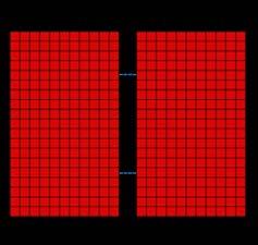
3 Page 2 of 44 Keywords Distortional lateral torsional buckling, partial twist restraints, web cleat angles, finite element analysis, principle of stationary total potential energy 1. Introduction Web cleats are commonly used as simple shear connections in steel construction. They consist of double angles of equal size (Figure 1). One leg of the cleat angle is connected to the beam while the other is typically connected to a column (not shown) either through bolts or fillet welds. When the beam span is long and when it is laterally unsupported between both ends, its flexural resistance is typically governed by lateral torsional buckling (LTB). Figure 2 depicts the beam cross section prior to loading, at the onset of buckling, and after LTB has occurred. The applied loads cause the cross-section to deflect vertically by a displacement v. When moments attain a critical magnitude, the beam reaches a point of instability at which it undergoes lateral translation u defined at the shear centre and a twist angle θ. At this point, the beam is unable to resist additional forces. In Fig. 2, in going from the initial position to the buckled configuration, the section is assumed to act as a rigid disk within its own plane, in line with the Vlasov first assumption (Vlasov 1961). Under the Vlasov classical lateral torsional buckling theory, the section s final configuration is fully characterized by only three displacements v, u, and θ leading to considerable simplifications in the solution. For beams with doubly symmetric wide flange cross-sections, steel design standards adopt, as a starting point, the classical closed form expression for the critical moment beam under uniform moments given by u of a simply supported [1] π π E = EI GJ + I C L L u y y w 2 in which L is the unbraced segment, E is the elasticity modulus, shear modulus, J is the Saint-Venant torsional constant, and expression is derived under the simply supported assumptions 0 I y is the weak axis moment of inertia, G is the C w is the warping constant. The critical moment u= u = θ = θ = at z 0, L =. Whether the 2
4 Page 3 of 44 Canadian Journal of Civil Engineering conditions u( ) θ( ) u( L) θ( L) 0 = 0 = = = 0 are fully realized in a beam with web cleat connections is unclear and is one of the motives of the present study. To generalize the solution for practical loading cases, various standards start with the uniform moment by Eq. [1] and modify it through a moment gradient factor u as given C s to account for more realistic moment distributions. The nominal critical moment thus takes the form n = C s u. As a matter of notation, subscript s takes the values CAN, AISC, AUS, or EUR to respectively denote the Canadian, American, and Australian standards, and the Eurocode guide. Factors C s are based on bending moment values at sampling points within the span. In the Canadian standards CAN/CSA S16-14, the moment gradient factor takes the form [2] C where CAN 4 max = A, max A B C B, and are the bending moments at quarter-span, mid-span, and three-quarter span points C within the unbraced segment, and ANSI/AISC (2010), it takes the form max is the maximum bending moment within the unbraced span. Under the [3] C AISC 12.5 max = max A B C while in the Australian standards AS 4100 (1998), it takes the form [4] C AUS 1.7 max = A B C The Euro-code guide (EN ) tabulates various moment gradient coefficients depending on the load distribution. For a point load acting at mid-span, it takes the value C EUR = Strictly speaking, when a beam buckles, its cross section does not act as a rigid disk as implied in the Vlasov assumption (Fig. 1c) but is susceptible to distortional deformation (Fig. 1d). Distortion is characterized by web deformation within the plane of the crosssection causing the top flange to twist by an angle θ T which is generally differs from that of the bottom flange leading to a lower LTB moment than predicted by the classical solution (based on the rigid disk assumption as depicted in Fig. 1c). In cold formed steel members, given the high slenderness of their cross-sectional elements, θ B 3
5 Page 4 of 44 distortional LTB has received comparatively more attention (AISI S ) than rolled sections with relatively thick webs which are generally thought as unsusceptible to distortional effects. This hypothesis is carefully examined in the present study through a systematic finite element analysis () parametric study. Fig. 1 (a) Web cleat connection at a beam end (b) LTB under the Vlasov Assumption, (c) Classical LTB and (d) Distortional LTB 2. Literature Review A comparative methodological review on distortional buckling formulations is provided in Pezeshky and ohareb (2014a). Rajasekaran and urray (1973) and Johnson and Will (1974) developed solutions to predict the distortional buckling capacity of wide flange members. Using the finite strip method, Hancock (1978) showed that typical beams undergo web distortion while flanges remain undistorted. Hancock et al. (1980) developed a distortional buckling solution for simply supported wide flange beam-columns under uniform moments. Bradford and Trahair (1981) developed a finite element buckling solution which captures distortional effects. Bradford and Trahair (1982) investigated moment gradient effects in lipped channels. Using a plate buckling distortional solution, Roberts and Jhita (1983) developed the buckling characteristic equation of wide flange sections. In a series of studies, Bradford developed distortional lateral buckling solutions for mono symmetric cross sections (Bradford 1985), inelastic buckling of I beams (Bradford 1986), mono symmetric I beams with continuous elastic lateral restrains (Bradford, 1988), beam columns (Bradford, 1990), cantilevers (Bradford 1992a), investigated the effects of end conditions, rotational and translational restraints for I beams (Bradford 1992b), and beams laterally restrained at one flange (Bradford and Ronagh, 1997). Wang et al. (1991) provided a comparison of distortional and non distortional buckling for mono symmetric simply supported beam columns. Hughes and a (1996a) developed a distortional buckling solution for simply supported monosymmetric I beams under point loads, and distributed transverse loads with unequal end moments (a and Hughes 1996). Dekker and Kemp (1998) developed a distortional buckling solution for I-Beams in which they idealized the flanges as translational and rotational springs, while treating the web as an elastic plate. Pi and Trahair (2000) developed effective torsional and warping rigidities for I-Beams which incorporate distortional effects. Using a Fourier series solution, Ng and Ronagh (2004) developed a distortional buckling solution for I-Beams which incorporates the effect of elastic restraints and load offset from the shear centre. Poon and Ronagh (2004) developed a distortional buckling model which idealizes the web lateral 4
6 Page 5 of 44 Canadian Journal of Civil Engineering displacement using a fifth order polynomial. Using shell analysis within the program BASP, Dowswell (2004) conducted a parametric distortional lateral torsional buckling of wide flange cantilevers. Based on shell analysis, Samanta and Kumar (2006) conducted a parametric distortional buckling analysis for simply supported monosymmetric I beams. Vrcelj and Bradford (2006) investigated the distortional buckling for I beams with the tension flange seated on a support. Zirakian and Showkati (2007) experimentally verified the occurrence of distortion in the buckled configuration in beams. Within the constrained finite strip method, Ádány and Schafer (2008) devised a mode decomposition technique to extract distortional buckling moments. Samanta and Kumar (2008) developed a parametric study on the distortional buckling capacity of cantilevers with mono symmetric I- sections in which they studied the effect of load position and bracing height. Using the finite strip method, Zirakian (2008) studied the distortional buckling of I beams and concluded that AISC recommendations for distortional lateral torsional buckling are conservative. By assuming a quadratic distribution of the web lateral displacement, Chen and Ye (2010) developed a distortional buckling solution for I beams and applied it for simply supported beams with a single restrained flange. Using the effective section properties developed by Pi and Trahair (2000), Kalkan and Buyukkaragoz (2012) quantified the elastic and inelastic distortional critical moments for beams and compared their results to AISC (2005), Eurocode 3 (2003) and AS 4100 (1998) recommendations. ost recently, Pezeshky and ohareb (2015) developed beam finite element solutions which capture distortional effects. A feature common to the above studies is that member ends were assumed either fully fixed, pinned, or entirely free. Within this context, the present study aims at determining the distortional lateral torsional buckling of beams with more realistic boundary conditions representative of typical end connections for beams. 3. Objectives The present study investigates the elastic distortional LTB resistance for beams with realistic end connections consisting of double web cleats welded at the toe to a supporting column and bolted to beam web (Fig. 1a). Beam sizes investigated are the W150, W200, and W310 series from the Canadian Institute of Steel Construction tables (CISC 2010). embers are subjected to mid-span point load acting at section mid-height. The study aims to (a) quantify the reduction in critical moments due to distortional effects, (b) assess whether the idealized boundary conditions u( ) θ( ) u( L) θ( L) 0 = 0 = = = 0 forming the basis of design procedures in standards are realized for the web cleat connection details, and (c) propose design rules which account for any deviations from idealized 5
7 Page 6 of 44 conditions observed under (a) or (b). The proposed design rules are intended for the design of beams for laterally unsupported beams bent about their strong axis commonly encountered in open steel framework in industrial structures, refineries, petrochemical plants, power plants, pipe racks, etc. 4. Finite Element Analysis 4.1 Selection of Parametric Runs A total of 42 runs were conducted. All W150 and W200 were analyzed. For the W310 series sections W310x21 through W310x107 were investigated. For W310 sections, since sections heavier than W310x107 would predominantly be used as columns rather than beams, they were discarded from the present study which focuses on flexural members. For the most part, beam spans were chosen to lie near the threshold of inelastic and elastic LTB based on CAN/CSA S standards predictions. As such, for Class 1 and 2 sections, span L was calculated by equating the inelastic LTB moment to 0.67 p and solving for the span L yielding in [5] π CCAN E 2I ycw L= 12m ( ) ( ) 1.76( ) y CAN y CAN p y w GJEI C + GJEI C + E I C For Class 3 sections, a similar equation is used while replacing of the plastic moment p with the yield moment y. Beams with spans less than L would fail by inelastic LTB, or yielding. In Eq. [5], the moment gradient factor was based on Eq. [2] which yielded C CAN = for the mid-span point load considered. Span L was then rounded up (to ensure that the member buckles elastically) to the nearest100mm. An upper limit of 12m was enforced in Eq. [5] since longer spans would likely involve splicing and would thus be infrequently encountered in practice. In 36 of the 42 runs, double cleat angles with L89x89x6.4 cross-sections were adopted while in the remaining six runs (runs 8a-d and 16a-b) the cleat angle thickness was varied to control the end twist restraints provided to the beam. Heights h c (Fig. 1a) for cleat angles were varied with beam depth. Design aids provided in CISC (2010) were used as guidelines for selecting the cleat angle height and bolt spacing. 6
8 Page 7 of 44 Canadian Journal of Civil Engineering 4.2 Finite Element odel A buckling eigenvalue analysis was conducted to extract the buckling loads and mode shapes. Steel was modelled as an elastic isotropic material with an elasticity modulus E= 200, 000Pa and a Poisson s ratioµ =0.3. The four-noded quadrilateral stress-displacement S4R shell element with reduced integration and a large-strain formulation was used to mesh the beam. A mesh sensitivity analysis for several W310 sections was conducted and resulted in element size of approximately 8mm 8mm. A typical mesh is shown in Fig. 2a. To simulate the boundary conditions of the welds connecting the cleat angle to the supporting column (Fig. 2a), nodal translations at the toes of the cleat angles were restrained along the entire length of the angle, along the x, y, and z directions. The flexibility of the supporting columns was neglected. Bolts were simulated through the use of the Discrete Fasteners feature in Abaqus (Fig. 2b, c). The modeling process involves identifying the surfaces to be fastened. In the present problem, these would be the beam web and both cleat angles. This is then followed by specifying the number of points to be fastened (i.e., the bolts), their coordinates, and radius of influence (i.e., bolt radius). The coupling type must then be specified. For the purpose of this study the Structural Coupling feature was chosen. Under this feature, the translational and rotational degrees of freedom for each fastening point were coupled to the translational and the rotational degrees of freedom of the group of coupled nodes on each of the fastened surfaces. In the present study, the degrees of freedom of the nodes within the specified radius of influence on the web cleats were coupled to those of the nodes within the radius of influence on the beam web. It is noted that the above procedure is distinct from node to node coupling. Rather, it is a weighted average of the rotations and translations of the nodes within the radius of influence on the beam is taken, and all the nodes within the radius of influence on the web cleats are coupled to that weighted average. No attempt was made to model the contact between the bolts and holes as such a model would have been possible in a nonlinear load-deformation analysis type rather than the eigenvalue analysis type sought in the present study. Fig. 2 Boundary Conditions and Abaqus model representation of (a) Radius of influence and (b) Fasteners In the model, in order to apply a mid-span load P at web mid-height while avoiding localized effects, the applied load was simulated by applying two equal point loads P 2 acting at the top and bottom web to flange junctions at the beam mid-span. 7
9 Page 8 of Finite Element Results 5.1 -predicted oment Gradient Factor For the runs, Table 1 lists the section designation, beam span L, cleat angle designation, and cleat angle height h c in Columns 2-5. Column 6 provides the twisting stiffness R provided by the web cleat connection to the supported beam as given by [6] GJ c 2Gh t R= = L 3L c 3 c c c where L c is the cleat span from the face of the supporting column to the bolt line (in all runs Lc was taken as 52.6 mm) and J c h c3 ct 3 = is the Saint-Venant torsional constant for a single leg (of thickness t c ) adjacent to the web. Coefficient 2 in Eq. 6 accounts for the presence of two cleat angles. Column 7 provides the relative twist stiffness 2 3 defined as α ( π w ) = GJ L+ EC L R. It represents the torsional stiffness of the beam (including the Saint- Venant and warping torsional contributions) to that of the end elastic rotational restraint R provided by the cleat angle. Column 8 provides the non-distortional critical moment uniform moments, based on the idealized boundary conditions u u θ θ 0 provides the critical distortional lateral torsional moment u (as obtained from Eq. 1) for the hypothetical case of = = = = at z 0, L = while Column 9 as predicted by the which accounts for (a) the non-uniform moment effect and (b) the partial end restraints as provided by the cleat angles. Column 10 provides the dimensionless ratio u which accounts for moment gradient, distortional effects, and partial fixity effects. Column 11 provides the ratio of the angle of twist θe at the beam end to that at mid-span θ as predicted by the. Strictly speaking, in a distorted section, each area segment of a cross-section undergoes a distinct angle of twist, i.e., the definition of the angle of twist of a cross-section is non-unique. Pezeshky and ohareb (2014b) proposed an area-averaged angle of twist indicator as a measure to characterize the twist of a distorted cross section and the area-averaged standard deviation of the angle of twist to characterize its distortion. In the present study, we adopt the following definitions for the end angle of twist 8
10 Page 9 of 44 Canadian Journal of Civil Engineering [7] (,, ) (,, ) θ = u u h θ E t E b E = u u h t b in which u t, E, u b, E are the lateral displacements at beam end at the top and bottom flange to web junctions, u t,, b, u are the mid-span lateral displacements at the top and bottom flange to web junction and h is the section height as measured between flange mid-surfaces. A ratio θe θ approaching zero indicates negligible end twist and suggests the classical boundary conditions θ( ) θ( L) 0 = = 0 are approached. The factor u (Column 10) is observed to range from to 1.401, with an average of This compares to moment gradients of (based CAN/CSA S16-14), (based on ANSI/AISC ), based onen ), and (based on AS ). On average, the ratio u is in reasonable agreement with moment gradients based on standards. However the scatter observed suggests an inconsistent level of safety in standard procedures. Figure 3a provides a comparison between the u ratio obtained by the present study to the moment gradient factors based on various standards. Of the 42 runs, standard provisions were observed to overestimate the critical moments in 20 cases for the Canadian Standards, 33 cases for the American standards, 39 cases for the Eurocode Guide, and 41 cases for the Australian standards. The large number of unconservative predictions is indicative of the fact that partial fixity conditions provided by cleat angles and distortional effects are not captured in present design provisions. Fig. 3 results (a) u ratio (b) lateral displacement profile at beam ends Table 1 Results of the parametric study 5.2 Assessing the End Lateral Fixity Condition In the derivation of the classical LTB solution, it is assumed that beam ends do not experience lateral displacements. To verify this assumption, dimensionless end lateral displacement profiles for runs 16, 16a, and 16b for the W200x100 beams are plotted in Fig. 3b. All displacements are normalized with respect to the mid-span displacement at the top flange, which corresponds to the largest displacement. It is observed that, irrespective of the twisting stiffness provided by the cleat angles, the web mid-height experiences a negligible lateral displacement of 9
11 Page 10 of 44 the order of 0.22% of the maximum lateral displacement. As such, the assumption of zero lateral displacement at the beams ends adopted in the classical solution appears to be vindicated. 5.3 Effect of End Twist Partial Fixity Condition The classical LTB solution given by Eq. [1] is based on the assumption that beam ends are fully restrained from twisting. Results in Column 11 of Table 1 show some twist deformation, suggesting that the classical assumption may be inaccurate in the present problem. The smallest -predicted moment gradient in Column 10 corresponds to Run 16 for the W200x100 beam (the heaviest section investigated) with the default cleat angles 2-L89x89x6.4. This case happens also to correspond to the largest end twist to the mid-span twist ratio of θ θ = (Column 10). This high θe θ ratio suggests that the default cleat angle size (L89x89x6.4, with a twisting stiffness R= 38.3kNm rad ) may not be fully effective in restraining the end twist deformation. To further investigate E this hypothesis, two additional runs were conducted with thicker cleat angles (runs 16a,b) with L89x89x9.5 cleat angles ( R 359 = knm rad ) and L89x89x13 ( R 125kNm rad = ). Indeed, an increase in the twist resistance provided by the cleats corresponded to an increase in the -predicted moment gradient from for the L89x89x6.4 cleat angle, to for the L89x89x9.5, to for the L89x89x13. Also, the corresponding θ θ ratio was observed to decrease from to , to , respectively. A similar observation can be E made by comparing the outcome of runs 8a-d, where the W310x52 beam cross-section and span of 5700 mm were kept constant, while the thickness of the cleat angles was increased from 6.4mm to 13mm. An increase in the partial twist restraint provided is thus concluded to reduce the angle of twist at beam ends and is associated with an increase in the LTB capacity of the system. 5.4 Effect of Distortion The previous section suggests that the variability in the predicted moment to the classical critical moment ratio (Column 10 of Table 1) is attributed to the degree of partial twist restraints provided by cleat angles. It is noted here that the degree of twist restraint is not the sole source in the scatter observed. This is verified by considering the results for run 8c (W310x52 with 2L89x89x8.7) and run 15 (W310x21 with 2L89x89x6.4). Both runs have identical relative twist stiffness ratios α = Yet, the corresponding predicted critical moment to classical critical moment ratio for run 8c is 1.262, a distinctly lower value from the ratio for run 15. The 10
12 Page 11 of 44 Canadian Journal of Civil Engineering reason for the difference becomes apparent when comparing the distorted buckled configurations of both beams (Fig. 4). As depicted, the web for run 8c undergoes more distortion than that of run 15. The degree of distortion is thus judged to play an important role in the scatter. A recent study on distortional buckling of beams under uniform moments (Hassan and ohareb 2012) has shown that distortional effects tend to increase with flange slenderness b / t, and aspect ratio b / h, as a larger and flange tends to attract more compressive stresses inducing distortion into the supporting flexible web. Both parameters are higher for the W310x52 section. The same study shows that distortional effects increase with web slenderness h / w. In this respect, the W310x52 has a lower slenderness. The higher flange slenderness b / t and aspect ratio b / h of the W310x52 section seem to offset the web slenderness effect, resulting into more distortion than the W310x21 section. 6. Developing Design Coefficients 6.1 General The classical LTB solution is based on three assumptions: 1) the beam is subject to uniform moment distribution, 2) ideal simply supported conditions, both in the lateral and torsional directions (i.e., the beam is fully restrained against lateral displacement and twist at both ends) and, 3) the beam cross-section exhibits no distortion. Assumption (1) is addressed in various standards through the introduction of moment gradient factor C. Regarding s assumption (2), Section 5.2 has revealed that the lateral restraint assumption appears to be valid while Section 5.3 suggested that end twist restraints provided by cleat angles are only partial. Assumption (3) appears to be only approximate given the distorted shapes shown in Fig. 4. Thus, modifications to standard procedures are needed to account for partial twist restraints at the ends and for cross-sectional distortion. Since the nominal elastic LTB resistance in various standards takes the form n = Cs u, which does not explicitly address distortional effects and partial end twist restraints, but solely incorporates the effect of moment gradient through apply three additional coefficients [8] = S DC ( C ) cr s R s u in which Coefficient C R, D, and S s to the standard design equation, i.e., C s, it is proposed to C R accounts for the partial twist restraint provided by the cleat, Coefficient D accounts for distortional effects as determined by results, and Coefficient S s is a standard constant which ensures that the 11
13 Page 12 of 44 critical moment predictions cr are consistent with those based on the code predictions (i.e., while Cs u presently varies from one standard to another, given the slightly different expressions for the moment gradient the present study will target a constant product cr = SsCs u to yield universal predictions among various standards). Sections develop expressions for the sought coefficients C, D, and 6.2 Formulating Coefficient for Partial Twist Restraint R S s, respectively. In this section, we consider the beam ends to be laterally restrained (as observed in Section 5.2) but partially restrained against twist (as concluded under Section 5.3) through a rotational spring of constant R at each end. The total potential energy [9] π p = Ub+ U R + V π p of the system is given by C s, where U b is the internal strain energy stored within the beam, U R is the energy stored within the cleat angles (treated as rotational springs), and V is the load potential energy gained by the moments as the beam undergoes LTB. The above energy contributions take the forms (e.g., Trahair 1993) [10]a-c L L L b = ( )'' ( )' ( )'', 2 y + 2 θ + wθ U EI u z dz GJ z dz EC z dz R 2 R 2 U R = θ( 0 ) θ( L), V ( z) u( z) '' θ( z) dz 2 + = 2 L 0 The mode shapes as observed in the provide a basis to assume displacement functions that are more realistic than those based on the classical solution. Approximate functions for lateral displacement ( u ) and angle of twist (θ ) which meet all essential and natural boundary conditions are π z π z u z = Asin, z = B+ C sin L L [11]a-b ( ) θ( ) The introduction of constant B in Eq. [11]b is consistent with the fact that in the, end rotations were observed to be non-zero, in contrast to the classical solution. For a simply supported beam with span L under mid-span loading, the bending moment ( z ) can be expressed in terms of the peak bending moments at mid-span 0 as 12
14 Page 13 of 44 Canadian Journal of Civil Engineering [12] ( ) z ( ) ( ) 2 z L 0 0 z L 2 = 2 1 z L 0 L 2 z L From Eqs. [10] and [11], by substituting into Eq. [9] and evoking the stationary conditions A π = B π = C π = 0, one obtains the neutral stability condition p p p [13] 4 2 π EI y π L L L 4 A R 0 B = 0 L C π 1 π GJ π EC w L 4 2 L L By setting the determinant of the matrix in Eq. [13] to zero, one recovers the critical moment expression [14] = ( π EI y 2L)( π GJ L+ π ECw L ) ( π + ) + ( R)( π GJ L+ π ECw L ) Taking the limit of the critical moment 0 as the rotational spring stiffness R tends to infinity, one obtains the critical moment for the idealized case where both ends are fully restrained from twisting as [15] π π π E π = lim = EI GJ + I C = R 2( π 4+ 1) L L 2( π 4+ 1) 0 2 y y w 2 u u As expected, when the ends of a beam are fully restrained, the critical moment obtained corresponds to a moment 2 2 gradient factor ( CE π ( π ) = = 1.423) multiplied by the uniform critical moment u, in a manner similar to expressions in various standards. The energy predicted moment gradient factor C E = derived is slightly larger than that provided in standards since: a) the assumed displacement and twisting functions postulated in Eqs. [11] are approximate, and b) the moment gradient coefficients based on quarter point formulas in standards are approximate. Improved moment gradient predictions can be obtained by postulating displacement functions involving more degrees of freedom, resulting in a larger size eigen-value problem. Alternatively, buckling analysis can be used to evaluate the moment gradients numerically using thin-walled beam models. Unlike shell models, beam models supress distortional effects. Three problems were investigated a W410x39 with a span of 13
15 Page 14 of m, a W410x39 with a span of 8.0m, and a W310x53 with a span of 5.7m. For each problem, two Eigen solutions were conducted: (1) the element of Barsoum and Ghallagher (1970) and the Thin walled beam element B31OS element in Abaqus. A mesh study was conducted in each case and the number of elements needed for convergence was determined (8 elements for the former solution and 40 for the later). The critical moments obtained were divided by the uniform critical moment given by the classical solution. In all cases, the moment gradient factors obtained ranged between and These values are in close agreement with the value reported in the Eurocode. Since the Eurocode provides specific values is for the given load patterns (mid-span load) as opposed to a generic quarter point formula, it yields accurate moment gradient factors. In contrast, the moment quarter point formulas in other standards, which are intended for general moment distributions, yield only approximate results for the present problem. The Canadian and American moment gradient factor formulas values of and err on the conservative side while the Australian moment gradient factor of is marginally unconservative. In the present study, we will retain the simplicity of the formulation provided in Eq. 14 while incorporating more accurate moment gradient expressions subsequently. Equation [14] can be expressed as = C C, C = [16]a-b ( ) 0 R E u R α where C R can be thought of as a reduction factor to be applied to the energy predicted critical moment CE u based on infinite twist resistance, and is intended to account for the partial twisting restraint. In Eq. [16]b, we recall 2 3 that the relative twist stiffness α ( π w ) = GJ L+ EC L R represents the torsional stiffness of the beam (consisting of the sum of the Saint-Venant and warping torsional stiffness) to that of the end elastic rotational restraint R provided by the cleat angles. 6.3 Formulating Distortional Coefficient For a given run i, given the critical moments as predicted from the, the energy-based moment gradient factor C E = 1.423, and the partial twist restraint coefficient from Eq. 16b, distortional coefficient ( ) D can be determined from D i [17] ( ) i = C C R E u i 14
16 Page 15 of 44 Canadian Journal of Civil Engineering The results for all runs are compiled in Table 2. As expected, distortional coefficient ( ) D is less than unity in all cases, except for run 16b, which involves a thick web connected to a thick cleat angle. It is reasoned that both thick components are able to transfer small negative moments at beam ends, causing a slight reduction in the positive moments at mid-span. The associated reduction in compressive stresses at mid-span reduces the destabilizing effect V as determined by Eq. 10a, and causes a slight increase in the predicted critical moment compared to the hypothetical case of zero end moments as implied by Eq. 12, and hence the higher ( ) i D. In design situations, it is impractical to conduct to quantify distortional effects. Thus, the present section develops an approximate expression to quantify critical moment reductions due to distortion. The distortional coefficient sought is based on regression analysis on the results obtained in Table 2. As discussed under Section 5.4, the distortional LTB moments to classical critical moment (excluding distortional effect) depend on w h, t b, b h (Hassan and ohareb 2012) for beams under linear moment gradients. We extend the observation to the present problem by postulating the following expression for the distortional coefficient i w L b t D= a + a + a + a + a h h h b [18] i i in which constants a 1 through a5 are obtained by minimizing the sum of the squares of errors [ D ] 2 i Di i yielding [19] w 3 L 2 b t D= h h h b where the ceiling value of 1.0 is consistent with the fact that distortional effects cannot increase the critical moment capacity based on physical grounds. Equation 19 is observed to give results within -4.5% to 3.6% of those based on D, with a standard deviation of 1.9%. Equation 16a and 19 can be combined to predict the distortional moment, i.e., [20] = D D = D( C C ) d 0 0 R E u Table 2 Comparison of buckling solutions and development of design coefficients 15
17 Page 16 of Standard Consistency Coefficient The distortional moments given in Eq. [20] are universal (i.e., non-standard dependent). However, given that the energy based moment gradient factor C is larger than that based on standards (i.e., C ), Eq. [16]a will tend to E S overestimate the critical moments for the case of infinite end twist stiffness (i.e., C R = 1.0 ) compared to the nominal moment capacity as predicted by standard provisions. Thus, to ensure consistency between the predictions of Eq. [20] and those based on standard provisions, we introduce a standard dependent consistency coefficient Ss = CE Cs such that the distortional critical moment cr can be related to C S (instead of C = D C C = DC C = S DC C [21] ( ) E cr R E u R s u s R s u Cs C E ) as follows which reverts to the format proposed in Eq. [8]. The consistency coefficients S s are SCAN = CE CCAN = = for the Canadian Standards, S AISC = CE CAISC = = for the American Standards, S = C C = = for the Eurocode, and EUR E EUR S AUS = CE CAUS = = for the Australian Standards. In Eq. [21], we recapitulate that the last two terms Cs u represent the critical moment including moment gradient effects as predicted by applicable standards, C R is a modifier introduced in Eq. [16]b which depends upon the degree of twist restraint provided by end cleats, D is a distortional modifier provided in Eq. [19] which depends on the geometric parameters of the cross-section and the span, and Ss is a standard dependent constant. 7. Design Considerations for Inelastic Lateral torsional buckling Standard provisions for inelastic lateral torsional buckling depend upon the yield or plastic moment as well as the elastic lateral torsional buckling resistance. While the present study has focused solely on improving means of prediction of the elastic lateral torsional buckling resistance, it did not attempt to verify/change the inelastic lateral torsional buckling equations to account for factors such inelastic material behavior, initial imperfections, and residual stresses. The authors nevertheless recommend the use of the improved critical moments obtained in the present study with existing inelastic lateral torsional buckling provisions in standards. The proposed approach is consistent with the method of design by advanced analysis recognized in the Australian standards (AS ) which allows the designer first to determine the elastic critical moment through a buckling eigenvalue analysis (in 16
18 Page 17 of 44 Canadian Journal of Civil Engineering this respect, the present study approximately predicts such critical moments through various coefficients derived), and then use the elastic critical moments in conjunction with standard provisions for inelastic buckling to account for inelastic effects, residual stresses, and initial imperfections. Such a concept was also recommended for the inelastic design of portal frames for inelastic lateral stability (Zinoviev and ohareb 2004). 8. Design Examples 8.1 Example 1 y A beam with a W410x39 cross-section ( F = 350Pa ) has a span of 4500mm. The beam is subject to a midspan load and is connected to rigid columns using double cleat angles at both ends. The cleat angles are L76x76x4.8 and are fastened to the beam web through 3-20mm A325 bolts. The distance between the angle heel to the bolt centerline is L 41mm c = while the cleat angle height is h 350mm c =. It is required to determine the maximum factored load that the beam can withstand. Design checks are to be performed according to present design standards CAN/CSA S16-14, ANSI/AISC as well as the design methodology proposed in the present study. Sectional properties are: beam depth d 399 = mm, flange width b= 140mm, flange thickness t 8.8mm =, web thickness w= 6.4mm, Saint-Venant constant J 3 4 = mm, out-of-plane moment of inertia I y 6 4 = mm, plastic section modulus about the x-axis Z x = 3 3, and warping constant mm Cw 9 6 = mm. The cleat angles have a thickness t = 4.8mm, and a Saint-Venant constant c Jc 3 4 = mm. CAN/CSA S16-14 Solution The section flange meets Class 2 requirements since b t= F = Also, the web meets el Class 2 requirements since h w= = F y = Hence, the design will be based on y the plastic moment resistance moment gradient factor CCAN p = Z xfy = 255.5kNm. The elastic LTB moment is CCAN u in which the is calculated based on the quarter point moment gradient equation, yielding the value C = for a beam under mid-span load. The resulting elastic LTB moment is CAN π π E CCAN u = CCAN GJEI y+ I ycw = (1.265)(96.3) = 121.8kNm L L 2 17
19 Page 18 of 44 Since C 0.67 CAN u p φ, the beam capacity is governed by elastic LTB and the factored flexural resistance is given by = C = 109.6kNm, and the corresponding factored load is then given by r CAN u Pf max = 4 r L= 97.4kN. ANSI/AIC Solution Since bel t= E Fy = 9.08 and h w= = E F y = 89.9, ANSI/ AISC also predicts compact section classification and the plastic moment resistance is = Z F = 255.5kNm. The elastic LTB moment is CAISC u in which the moment gradient factor CASIC p x y is calculated based on the quarter point moment gradient equation, yielding the value C AISC = for a beam under mid-span load. The resulting elastic LTB moment is π π E CAISC u = CAISC GJEI y+ I ycw = (1.316)(96.3) = 126.7kNm L L 2 Since C 0.7 AISC u p, the beam capacity is governed by elastic LTB and the flexural resistance is given by = φc = 114.1kNm, and the corresponding factored load is then given by r AISC u Pf max = 4 r L= 101.4kN. Proposed Solution The above solutions do not account for partial twist restraints provided by the cleat angles, nor do they account for distortional effects. In contrast, the proposed design methodology accounts for these effects as described below. To determine the partial twist restraint coefficient C, the twisting stiffness are determined for cleat angles, i.e., 3 ( ) R R= GJ L = 2G h t 3 L = 48.4 knm / rad and the corresponding twist stiffness dimensionless ratio c c c c c 2 3 is α ( R)( GJ L π ECw L ) = 1 + = yielding a reduction R C value of CR ( α) = = This signifies that since the twist restraint of the web cleat connection is only partial, a reduction factor of 92.2% needs to be applied to the critical moment as determined based on an idealized infinitely rigid twist connection. The factor accounting for reduction due to distortion, D is then determined 18
20 Page 19 of 44 Canadian Journal of Civil Engineering 3 2 from D= + ( w h) ( L h) ( b h) ( t b) = This result suggests that, in order to account for distortional effects, a factor of needs to be applied to the solution provided by standards which does not incorporate distortional effects. The corresponding critical moment is ( φ ) = DC C cr R CAN u = (0.947)(0.922)(109.6) = 95.7kNm and the corresponding factored load P is then given by P max = 4 L= 85.0kN. If consistent results are f max f cr to be obtained under both standards, the consistency coefficients S s = 1.081for ANSI/AISC and S = for CAN/CSA S16-14 need to be applied to the above solution. The resulting critical moments are then s obtained as ANSI/AISC CAN/CSA S16-14 f max ( φ ) = DC S C cr R s s u P = 4 L= 95.7kN cr f max ( φ ) = DC S C cr R s s u = (0.947)(0.922)(1.081)(114.1) = (0.947)(0.922)(1.125)(109.6) = 107.6kNm = 107.6kNm P = 4 L= 95.7kN cr Finite Element Solution The nominal critical moments based on are found to be 124.1kNm and the corresponding factored critical load is 111.7kN. Comparison Table 3 provides a summary of the moment predictions by various methods. The solution is used in the last column of the table as benchmark solution against which other solutions are assessed. For the given problem, the CAN/CSA S16-14 procedure underestimates the critical moments by 1.9% while ANSI/AISC overestimates them by 2.1%. By disregarding the consistency coefficient, and retaining the partial twist restraint and distortional coefficients, the modified CAN/CSA S16-14 is observed to underestimate the critical moment by 14% and the modified ANSI/AISC by 11%. After incorporating the consistency coefficients, both standards are found to underestimate the capacity of the beams by 3.7%. For the chosen example, present design standards provide predictions in excellent agreement with results. However, since both standards do not involve means to directly 19
21 Page 20 of 44 capture distortional effects nor partial twist restraints at both ends, such agreement with results will not always be attained as illustrated in the following example. Table 3 Critical moments for a 4.5m span W410x39 beam with 2-L76x76x4.8 cleat angles at both ends It is required to revise the capacity of the beam in Example 1 if the supporting cleat angles are replaced with thicker L76x76x9.5. The twist stiffness of the new cleat angles would increase to R= 375kNm rad, and the corresponding results are summarized in Table 4. As expected, a thicker cleat angle results in a critical moment as determined by that is higher by about 6.3% compared to that based on the thinner cleat angle (L76x76x4.8). Again, the predicted moments will serve as a basis to assess the quality of other solutions. The beneficial effect of the thicker cleat angles is not captured by present design rules in CAN/CSA S16-14 nor ANSI/AISC , which result in lower moment resistance ratios of 92.3% and 96.1%, respectively. Under the proposed solution, the partial twist restraint coefficient C R is observed to increase from to 0.989, a 7.3% difference. The proximity of the new value of C R to unity suggests that the thicker cleat angle provides near full twist fixity to beam ends. This increase in C is associated with a proportional increase in the predicted critical moments. As a result, the modified procedures (which accounts for moment gradient factor, coefficient D, but discarding R C R and distortional S s ) the r ratios that are found to be nearly identical to those reported for Example 1, i.e., the moment ratios are and for CAN/CSA S16-14 and ANSI/AISC , respectively. When the consistency factor is incorporated into the solution, both modified standards are observed to yield predictions in closer agreement with. In both cases, and r moment ratio of is achieved, i.e., the proposed modified procedure predicts the solution within 2.8%. Table 4 Critical moment for a 4.5m span W410x39 beam with 2-L76x76x9.5 cleat angles at both ends Example 3: A 12 m span beam has a W200x100 cross-section. The beam is subject to a mid-span load and is connected to rigid columns at both ends using L89x89x6.4 double cleat angles. Cleats are fastened to the beam web through 2-20mm A325 bolts. The distance between the angle heel to the bolt centerline is L = 52.6mm while the cleat angle height is h = 150mm. It is required to determine the flexural capacity of the beam according to CAN/CSA S16- c c 20
22 Page 21 of 44 Canadian Journal of Civil Engineering 14 standards, the present study, and compare them to that based on. Two steel strengths are to be investigated Fy = 400Pa, and F = 480Pa y CAN/CSA S16-14 Solution For the case of F = 400Pa, the section is found to be Class 2 since b t= F y and h w= Fy. Hence, the design will be based on the plastic moment resistance = Z F = 460.0kNm. Given the moment gradient C = 1.265, one obtains p x y CAN el y 2 π π E = C = C GJEI + I C = (1.265)(288.8) = 365.3kNm= 0.79 L L u CAN u CAN y y w P Since u 0.67 p, the beam capacity is governed by inelastic LTB, and the factored flexural resistance is p = φ = = 308.2kNm u r p p Proposed odified CAN/CSA Solution The twisting stiffness R of the cleat angles is determined as R= GJ L = 38.3 knm / rad which corresponds c c 2 3 to a twist stiffness dimensionless α ( R) GJ L ( π ECw L ) = 1 + = yielding a reduction C R value of C ( α) R = = The distortional coefficient is given by D w L b t h h h b 3 2 = = 0 The corresponding nominal elastic LTB resistance based on the proposed modifications is = S DC C = = 318.8kNm= u CSA R CSA u p Since u 0.67 given by p, the beam capacity is governed by inelastic LTB, and the factored flexural resistance is p = φ = = 283.7kNm u r p p Finite Element Solution 21
23 Page 22 of 44 Given that = 333kNm, the factored flexural resistance would be u p r = φ1.15 p = = 291.9kNm u 333 Therefore, for the case of F = 400Pa, the Canadian Standard solution over-predicts the beam capacity by y 5.6% compared to the finite element solution while the proposed modified solution under-predicts the critical moment by 2.8%. For the case of the higher yield strength steel F = 480Pa, the plastic moment increases to y = Z F = knm and the design is found to be governed by elastic lateral torsional buckling. The p x y CAN-CSA solution predicts a resisting moment of φ u = = knm while the proposed modified r procedure predicts a resisting moment of = φ u = 286.9kNm. These values compare with r. = φ = 300.0kNm as based on the solution. In this case, the Canadian standards r u underestimate the critical moment by 6.9% while the modified procedure underestimates it by 4.4% 9. Summary, Conclusions and Recommendations (1) A buckling parametric study consisting of 42 runs was conducted based on shell on common size beams with typical double angle cleat connections. The analyses have shown that such members undergo some distortional effects. Also, angle cleat connections were shown to provide only partial twist restraint to member ends. (2) On average, for the beam and connection configurations investigated, is found to predict critical moments in line with those based on design standards. However, some scatter is observed compared to standard design values. The present Canadian standard provisions provide the best agreement with results with 20 out of 42 cases being overestimated. Comparatively, the American standards, Eurocode guide, and Australian standards overestimate the critical moments in 33, 39, and 41 cases respectively. (3) Starting with present standard provisions, the present study developed three modifiers to be applied to the critical moment equations: (1) a coefficient for partial twist restraint, (2) a distortional coefficient, and (3) a standard consistency coefficient. (4) The twist stiffness coefficient is based on an energy formation and successfully incorporates the effect of partial twisting restraint provided by cleat angle connections on the critical moments of beams. The distortional 22
24 Page 23 of 44 Canadian Journal of Civil Engineering coefficient is based on regression analysis and captures the reduction in critical moments based on the geometric parameters of the member. (5) The proposed design methodology consistently yields predictions in closer agreement to shell based results than all those based on all four standards examined. (6) The quality of the solution presented herein hinges on the validity of the model developed. In this respect, it is worthwhile to note that similar Abaqus S4R shell modeling has been validated against full-scale LTB fullscale tests for Gerber beam systems (Nowzartash et al. 2011). Also, it was shown to approach the classical flexural and torsional buckling solutions for columns (Dabbas 2002). Through comparisons with beam solutions, similar S4R shell models were successful to quantify the effect of distortional effects on lateral buckling resistance in portal frames (Wu and ohareb 2013), LTB of beams with doubly symmetric sections (Erkmen and ohareb 2008 and Wu and ohareb 2011), and LTB of beams and beam columns with monosymmetric sections (Erkmen and ohareb 2008 and Saharei et al. 2015). Nevertheless, it is still desirable to conduct careful experimental studies involving the specific connection details investigated in the present study in order to (a) assess the impact of the simplifications introduced in when modelling the connections, (b) quantify the critical moments and compare them with the present predictions, and (c) experimentally verify and observe the end twist effects and distortional phenomena predicted by the present model. Acknowledgments: The authors gratefully acknowledge funding from the Natural Science and Engineering Research Council of Canada (NSERC) to the second author. References: Ádány, S., and Schafer, B.W A full modal decomposition of thin-walled, single-branched open cross-section members via the constrained finite strip method, Journal of Constructional Steel Research, 64: AISI S (2007), North American Specification for Design of Cold-Formed Steel Structural embers, American Iron and Steel Institute, Washington, D. C. American Institute of Steel Construction (AISC) Specification for structural steel buildings. Chicago, IL. AS Steel Structures, Standards Association of Australia. Sydney, Australia. 23
25 Page 24 of 44 Bradford,. A. and Trahair, N. S Distortional Buckling of I Beams, Journal of the Structural Division, ASCE, 107: Bradford,. A. and Trahair, N. S Distortional buckling of thin web beam columns, Engineering Structures, 4:2 10. Bradford,. A Distortional buckling of monosymmetric I beams, Journal of Constructional Steel Research, 5: Bradford,. A Inelastic distortional buckling of I beams, Computers & Structures, 24: Bradford,. A Buckling of elastically restrained beams with web distortions, Thin Walled Structures, 6: Bradford,. A Stability of mono symmetric beam columns with thin webs, Journal of Constructional Steel Research, 15: Bradford,. A. 1992a. Buckling of doubly-symmetric cantilevers with slender webs, Engineering Structures, 14: Bradford,. A. 1992b. Lateral-Distortional buckling of steel I section members, Journal of Constructional Steel Research, 23: Bradford,.A., and Ronagh, H. R Generalized elastic buckling of restrained I-beams by FE, Journal Structural Engineering, ASCE, 123: CISC (2010) Handbook of Steel Construction, Tenth Edition, Canadian Institute of Steel Construction, arkham, Ontario, Canada CSA Limit states design of steel structures. Standard CAN/CSA-S16-14, Canadian Standards Association, ississauga, Ontario Dekker, N.W., and Kemp, A. R A simplified distortional buckling model for doubly symmetrical I-sections, Canadian Journal of Civil Engineering, 25: Chen, W.E.I., and Ye, J Elastic lateral and restrained distortional buckling of doubly symmetric I-beams, International Journal of Structural Stability and Dynamics, 10. pp Dabbas, A. (2002), Lateral Stability of Partially Restrained Cantilever Supports,. Eng. Report, University of Ottawa, ON, Canada 24
26 Page 25 of 44 Canadian Journal of Civil Engineering Dekker, N.W., and Kemp, A. R A simplified distortional buckling model for doubly symmetrical I-sections, Canadian Journal of Civil Engineering, 25: Dowswell, B. (2004). Lateral-Torsional Buckling of Wide Flange Cantilever Beams, Engineering Journal, AISC, 41: Eurocode : Design of steel structures Part 1 1: general rules and rules for buildings, European Committee for Standardization (CEN), Brussels, Belgium. Erkmen, R. E. and ohareb,., (2008), Buckling Analysis of Thin-walled Open embers - A Finite Element Formulation, Thin-walled structures, Vol. 46(6), pp Hancock, G. J Local, Distortional, and Lateral Buckling of I Beams. Journal of the Structural Division, 104: Hancock, G.J., Bradford,.A., and Trahair, N.S Web distortion and flexural-torsional buckling, Journal of the Structural Division, ASCE, 106: Hassan, R. and ohareb,. (2012), Distortional lateral torsional buckling analysis for beams of wide flange crosssections, 3rd International Structural Specialty Conference, CSCE, Edmonton, Alberta Hughes, O., and a,. 1996a. Lateral distortional buckling of monosymmetric beams under point load, Journal of Engineering echanics, ASCE, 122: Johnson, C. P., and Will, K Beam Buckling by Finite Element Procedure, Journal of the Structural Division, 100: Kalkan, I., and Buyukkaragoz, A. (2012). A numerical and analytical study on distortional buckling of doublysymmetric steel I-beams, Journal of Constructional Steel Research, 70: a,., and Hughes,. 1996b. Lateral distortional buckling of monosymmetric I-beams under distributed vertical load, Thin-Walled Structures, 26: Nowzartash F., arkiz N., and ohareb,. 2012, Analysis and Testing of Gerber Frames for Lateral Stability, Third International Specialty Conference, Canadian Society of Civil Engineering, Edmonton, Canada, ay Ng,. L-H., and Ronagh, H. R An analytical solution for the elastic lateral-distortional buckling of I-section beams. Advances in Structural Engineering, 7: Pezeshky, P., and ohareb,.2014a. Distortional theory for the analysis of wide flange steel beams, Engineering Structures, 75:
27 Page 26 of 44 Pezeshky, P, and ohareb, 2014b. Objective measures for characterizing distortion in wide flange steel sections, 4th International Structural Specialty Conference, Halifax, Nova Scotia, Canada, ay Pezeshky, P. and ohareb,., Finite Element Formulations for the Distortional Analysis of Wide Flange Steel Beams, Journal of Engineering echanics, /(ASCE)E , Pi, Y., and Trahair, N Distortion and warping at beam supports. Journal of Structural Engineering, 126: Poon, C. P. and Ronagh, H. R. (2004). Distortional Buckling of I-Beams by Finite Element ethod, Advances in Structural Engineering, 7(1), Rajasekaran, S., and urray D. W Coupled Local Buckling in Wide Flange Beam Columns, Journal of the Structural Division, 99: Roberts, T.. and Jhita, P. S. (1983) Lateral, local and distortional buckling of I beams, Thin Walled Structures, 1: Sahraei, A., Wu, L., and ohareb, Finite Element Formulation for Lateral Torsional Buckling Analysis of Shear Deformable ono-symmetric Thin-walled embers, Thin-Walled Structures, 89, Samanta, A., and Kumar, A Distortional buckling in monosymmetric I-beams, Thin-Walled Structures, 44: Samanta, A., and Kumar, A Distortional buckling in braced-cantilever I-beams, Thin-Walled Structures, 46: Timoshenko, S. P. and Gere, J.. (1961), Theory of Elastic Stability, cgraw Hill, New York Vrcelj Z., and Bradford.A., (2006). Elastic distortional buckling of continuously restrained I-section beam column, Journal of Constructional Steel Research, 62: Vlasov V. Z Thin walled elastic beams, Available from Office of Technical Services, US Department of Commerce, Washington, D.C.: Israel Program for Scientific Translations. 2nd ed, Jerusalem, Israel Wang, C.., Chin C.K., and Kitipornchai, S Parametric study on distortional buckling of monosymmetric beam-columns, Journal of Constructional Steel Research, 18: Wu, L. and ohareb, Buckling Formulation for Shear Deformable Thin-Walled embers- II. Finite Element Formulation, Thin-walled Structures, 49(1), pp
28 Page 27 of 44 Canadian Journal of Civil Engineering Wu, L. and ohareb., Finite Element Formulation for the Lateral Torsional Buckling of Plane Frames, Journal of Engineering echanics, 139(4), Zirakian, T. and Showkati, H Experiments on Distortional Buckling of I-beams, Journal of Structural Engineering, 133: Zinoviev, I. and ohareb, Analysis and Design of Laterally Unsupported frames for out-of-plane stability, Canadian Journal of Civil Engineering, Vol. 31(3), pp Zirakian, T Elastic distortional buckling of doubly symmetric I-shaped flexural members with slender webs, Thin-Walled Structures, 46:
29 Page 28 of 44 List of Figures Fig. 1 (a) Web cleat connection at a beam end (b) LTB under the Vlasov Assumption, (c) Classical LTB and (d) Distortional LTB Fig. 2 Boundary Conditions and Abaqus model representation of (a) Radius of influence and (b) Fasteners Fig. 3 results (a) u ratio (b) lateral displacement profile at beam ends Fig. 4- Distortion in two beams with identical relative twist stiffness; (a) Run 8c with W310x52 section and an 8.7mm thick cleat angle; and (b) Run 15 with W310x21 section and a 6.4mm thick cleat angle. List of Tables Table 1 Results of the parametric study Table 2 Comparison of buckling solutions and development of design coefficients Table 3 Critical moments for a 4.5m span W410x39 beam with 2-L76x76x4.8 cleat angles at both ends Table 4 Critical moment for a 4.5m span W410x39 beam with 2-L76x76x9.5 cleat angles at both ends 28
30 Page 29 of 44 Canadian Journal of Civil Engineering t c Supported Beam b t v Initial Position - Prior to Loading Angle L c h c Bolts w d Deflected Position At Onset of Buckling u θ Final Buckled Position (a) (b) θ T θ T θ B θ B θ (c) T B = θ (d) θt θb


")
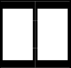
31 Page 30 of 44 A Radius of Influence Fastener A A-A (a) (b) (c)
32 Page 31 of 44 Canadian Journal of Civil Engineering (a) (b)
")
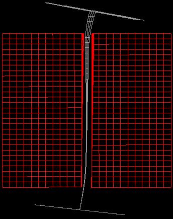
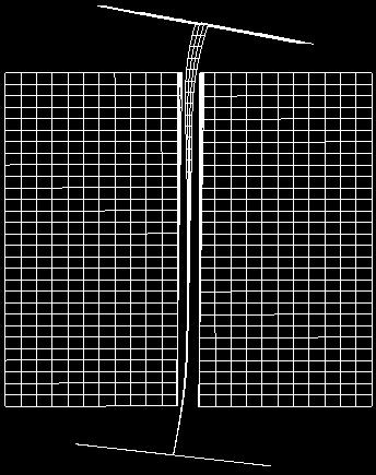
33 Page 32 of 44 (a) (b)
Equivalent Uniform Moment Factor for Lateral Torsional Buckling of Steel Beams
 University of Alberta Department of Civil & Environmental Engineering Master of Engineering Report in Structural Engineering Equivalent Uniform Moment Factor for Lateral Torsional Buckling of Steel Beams
Accordingly, the nominal section strength [resistance] for initiation of yielding is calculated by using Equation C-C3.1.
![Accordingly, the nominal section strength [resistance] for initiation of yielding is calculated by using Equation C-C3.1.](/thumbs/89/98617066.jpg "Accordingly, the nominal section strength [resistance] for initiation of yielding is calculated by using Equation C-C3.1.") C3 Flexural Members C3.1 Bending The nominal flexural strength [moment resistance], Mn, shall be the smallest of the values calculated for the limit states of yielding, lateral-torsional buckling and distortional
C3 Flexural Members C3.1 Bending The nominal flexural strength [moment resistance], Mn, shall be the smallest of the values calculated for the limit states of yielding, lateral-torsional buckling and distortional
Experimental Study and Numerical Simulation on Steel Plate Girders With Deep Section
 6 th International Conference on Advances in Experimental Structural Engineering 11 th International Workshop on Advanced Smart Materials and Smart Structures Technology August 1-2, 2015, University of
Design of Beams (Unit - 8)
") Design of Beams (Unit - 8) Contents Introduction Beam types Lateral stability of beams Factors affecting lateral stability Behaviour of simple and built - up beams in bending (Without vertical stiffeners)
Design of Beams (Unit - 8) Contents Introduction Beam types Lateral stability of beams Factors affecting lateral stability Behaviour of simple and built - up beams in bending (Without vertical stiffeners)
TORSION INCLUDING WARPING OF OPEN SECTIONS (I, C, Z, T AND L SHAPES)
") Page1 TORSION INCLUDING WARPING OF OPEN SECTIONS (I, C, Z, T AND L SHAPES) Restrained warping for the torsion of thin-wall open sections is not included in most commonly used frame analysis programs. Almost
Page1 TORSION INCLUDING WARPING OF OPEN SECTIONS (I, C, Z, T AND L SHAPES) Restrained warping for the torsion of thin-wall open sections is not included in most commonly used frame analysis programs. Almost
Influence of residual stresses in the structural behavior of. tubular columns and arches. Nuno Rocha Cima Gomes
 October 2014 Influence of residual stresses in the structural behavior of Abstract tubular columns and arches Nuno Rocha Cima Gomes Instituto Superior Técnico, Universidade de Lisboa, Portugal Contact:
research report Design Example for Analytical Modeling of a Curtainwall and Considering the Effects of Bridging (All-Steel Design Approach)
") research report Design Example for Analytical Modeling of a Curtainwall and Considering the Effects of Bridging (All-Steel Design Approach) RESEARCH REPORT RP18- August 018 Committee on Specifications
research report Design Example for Analytical Modeling of a Curtainwall and Considering the Effects of Bridging (All-Steel Design Approach) RESEARCH REPORT RP18- August 018 Committee on Specifications
Structural Steelwork Eurocodes Development of A Trans-national Approach
 Structural Steelwork Eurocodes Development of A Trans-national Approach Course: Eurocode Module 7 : Worked Examples Lecture 0 : Simple braced frame Contents: 1. Simple Braced Frame 1.1 Characteristic Loads
Failure in Flexure. Introduction to Steel Design, Tensile Steel Members Modes of Failure & Effective Areas
 Introduction to Steel Design, Tensile Steel Members Modes of Failure & Effective Areas MORGAN STATE UNIVERSITY SCHOOL OF ARCHITECTURE AND PLANNING LECTURE VIII Dr. Jason E. Charalambides Failure in Flexure!
NUMERICAL EVALUATION OF THE ROTATIONAL CAPACITY OF STEEL BEAMS AT ELEVATED TEMPERATURES
 8 th GRACM International Congress on Computational Mechanics Volos, 12 July 15 July 2015 NUMERICAL EVALUATION OF THE ROTATIONAL CAPACITY OF STEEL BEAMS AT ELEVATED TEMPERATURES Savvas Akritidis, Daphne
MODULE C: COMPRESSION MEMBERS
 MODULE C: COMPRESSION MEMBERS This module of CIE 428 covers the following subjects Column theory Column design per AISC Effective length Torsional and flexural-torsional buckling Built-up members READING:
Lateral Torsional Buckling of Welded Wide Flange Beams
 Lateral Torsional Buckling of Welded Wide Flange Beams Md. Imran Kabir A Thesis in The Department of Building, Civil and Environmental Engineering Presented in Partial Fulfillment of the Requirements for
Flexural-Torsional Buckling of General Cold-Formed Steel Columns with Unequal Unbraced Lengths
 Proceedings of the Annual Stability Conference Structural Stability Research Council San Antonio, Texas, March 21-24, 2017 Flexural-Torsional Buckling of General Cold-Formed Steel Columns with Unequal
Structural Steelwork Eurocodes Development of A Trans-national Approach
 Structural Steelwork Eurocodes Development of A Trans-national Approach Course: Eurocode 3 Module 7 : Worked Examples Lecture 20 : Simple braced frame Contents: 1. Simple Braced Frame 1.1 Characteristic
A RATIONAL BUCKLING MODEL FOR THROUGH GIRDERS
 A RATIONAL BUCKLING MODEL FOR THROUGH GIRDERS (Hasan Santoso) A RATIONAL BUCKLING MODEL FOR THROUGH GIRDERS Hasan Santoso Lecturer, Civil Engineering Department, Petra Christian University ABSTRACT Buckling
A Parametric Study on Lateral Torsional Buckling of European IPN and IPE Cantilevers H. Ozbasaran
 Vol:8, No:7, 214 A Parametric Study on Lateral Torsional Buckling of European IPN and IPE Cantilevers H. Ozbasaran Abstract IPN and IPE sections, which are commonly used European I shapes, are widely used
3. Stability of built-up members in compression
 3. Stability of built-up members in compression 3.1 Definitions Build-up members, made out by coupling two or more simple profiles for obtaining stronger and stiffer section are very common in steel structures,
SUMMARY FOR COMPRESSION MEMBERS. Determine the factored design loads (AISC/LRFD Specification A4).
.") SUMMARY FOR COMPRESSION MEMBERS Columns with Pinned Supports Step 1: Step : Determine the factored design loads (AISC/LRFD Specification A4). From the column tables, determine the effective length KL using
SUMMARY FOR COMPRESSION MEMBERS Columns with Pinned Supports Step 1: Step : Determine the factored design loads (AISC/LRFD Specification A4). From the column tables, determine the effective length KL using
An Increase in Elastic Buckling Strength of Plate Girder by the Influence of Transverse Stiffeners
 GRD Journals- Global Research and Development Journal for Engineering Volume 2 Issue 6 May 2017 ISSN: 2455-5703 An Increase in Elastic Buckling Strength of Plate Girder by the Influence of Transverse Stiffeners
Improved Flexural Design Provisions for I-Shaped Members and Channels
 Improved Flexural Design Provisions for I-Shaped Members and Channels DONALD W. WHITE Donald W. White is Associate Professor, Structural Engineering, Mechanics and Materials, Georgia Institute of Technology,
of I Section Members
 IMPROVED DESIGN ASSESSMENT OF LTB OF I-SECTION MEMBERS VIA MODERN COMPUTATIONAL METHODS Improved Design Assessment of LTB of I Section Members Donald W. White (with credits to Dr. Woo Yong Jeong & Mr.
Finite Element Modelling with Plastic Hinges
 01/02/2016 Marco Donà Finite Element Modelling with Plastic Hinges 1 Plastic hinge approach A plastic hinge represents a concentrated post-yield behaviour in one or more degrees of freedom. Hinges only
CHAPTER 5 PROPOSED WARPING CONSTANT
 122 CHAPTER 5 PROPOSED WARPING CONSTANT 5.1 INTRODUCTION Generally, lateral torsional buckling is a major design aspect of flexure members composed of thin-walled sections. When a thin walled section is
Chapter 12 Elastic Stability of Columns
 Chapter 12 Elastic Stability of Columns Axial compressive loads can cause a sudden lateral deflection (Buckling) For columns made of elastic-perfectly plastic materials, P cr Depends primarily on E and
APPLICATIONS OF PURE AND COMBINED BUCKLING MODE CALCULATION OF THIN-WALLED MEMBERS USING THE FINITE ELEMENT METHOD
 SDSS Rio 2010 STABILITY AND DUCTILITY OF STEEL STRUCTURES E. Batista, P. Vellasco, L. de Lima (Eds.) Rio de Janeiro, Brazil, September 8-10, 2010 APPLICATIONS OF PURE AND COMBINED BUCKLING MODE CALCULATION
SIMPLE MODEL FOR PRYING FORCES IN T-HANGER CONNECTIONS WITH SNUG TIGHTENED BOLTS
 SIMPLE MODEL FOR PRYING FORCES IN T-HANGER CONNECTIONS WITH SNUG TIGHTENED BOLTS By Fathy Abdelmoniem Abdelfattah Faculty of Engineering at Shoubra, Zagazig University, Banha Branch Mohamed Salah A. Soliman
The Lateral Torsional Buckling Strength of Steel I- Girders with Corrugated Webs
 Lehigh University Lehigh Preserve ATLSS Reports Civil and Environmental Engineering 5-1-6 The Lateral Torsional Buckling Strength of Steel I- Girders with Corrugated Webs Daming Yu Richard Sause Follow
Design of Axially-loaded Wide-flange Columns Subjected to Torsion Through One Flange. Riley Quintin
 Design of Axially-loaded Wide-flange Columns Subjected to Torsion Through One Flange by Riley Quintin A thesis submitted in partial fulfillment of the requirements for the degree of Master of Science in
A numerical investigation of local web buckling strength and behaviour of coped beams with slender web
 A numerical investigation of local web buckling strength and behaviour of coped beams with slender web *Michael C. H. Yam 1), Ke Ke 2), Angus C. C. Lam 3), Cheng Fang 4), and K. F. Chung 5) 1), 2) Department
A numerical parametric study on the plate inclination angle of steel plate shear walls
 Journal of Structural Engineering & Applied Mechanics 219 Volume 1 Issue 4 164-173 https://doi.org/1.31462/jseam.219.1164173 www.goldenlightpublish.com RESEARCH ARTICLE A numerical parametric study on
DES140: Designing for Lateral-Torsional Stability in Wood Members
 DES140: Designing for Lateral-Torsional Stability in Wood embers Welcome to the Lateral Torsional Stability ecourse. 1 Outline Lateral-Torsional Buckling Basic Concept Design ethod Examples In this ecourse,
Civil. Engineering INELASTIC BENDING CAPACITY IN COLD-FORMED STEEL MEMBERS Annual Stability Conference New Orleans, Louisiana
 Civil Engineering at JOHNS HOPKINS UNIVERSITY at JOHNS HOPKINS UNIVERSITY INELASTIC BENDING CAPACITY IN COLD-FORMED STEEL MEMBERS 2007 Annual Stability Conference New Orleans, Louisiana April 2007 Y.Shifferaw
Workshop 8. Lateral Buckling
 Workshop 8 Lateral Buckling cross section A transversely loaded member that is bent about its major axis may buckle sideways if its compression flange is not laterally supported. The reason buckling occurs
Lateral Buckling of Singly Symmetric Beams
 Missouri University of Science and Technology Scholars' Mine International Specialty Conference on Cold- Formed Steel Structures (1992) - 11th International Specialty Conference on Cold-Formed Steel Structures
ENCE 455 Design of Steel Structures. III. Compression Members
 ENCE 455 Design of Steel Structures III. Compression Members C. C. Fu, Ph.D., P.E. Civil and Environmental Engineering Department University of Maryland Compression Members Following subjects are covered:
Karbala University College of Engineering Department of Civil Eng. Lecturer: Dr. Jawad T. Abodi
 Chapter 05 Structural Steel Design According to the AISC Manual 13 th Edition Analysis and Design of Beams By Dr. Jawad Talib Al-Nasrawi University of Karbala Department of Civil Engineering 71 Introduction
Torsional Analysis of
 Steel Design Guide Series Torsional Analysis of Structured Steel Members Steel Design Guide Series Torsional Analysis of Structural Steel Members Paul A. Seaburg, PhD, PE Head, Department of Architectural
Reports RESEARCH REPORT RP00-3 RESEARCH REPORT RP01-1 OCTOBER REVISION 2006 REVISION
 research report A AISI Design Sponsored Approach Resear for ch Complex Reports AISI Sponsored Stiffeners Research Reports RESEARCH REPORT RP00-3 RP01-1 RESEARCH REPORT RP01-1 OCTOBER 2001 2000 REVISION
University of Sheffield. Department of Civil Structural Engineering. Member checks - Rafter 44.6
 Member checks - Rafter 34 6.4Haunch (UB 457 x 191 x 89) The depth of a haunch is usually made approximately twice depth of the basic rafter sections, as it is the normal practice to use a UB cutting of
Design of Steel Structures Prof. S.R.Satish Kumar and Prof. A.R.Santha Kumar
 5.4 Beams As stated previousl, the effect of local buckling should invariabl be taken into account in thin walled members, using methods described alread. Laterall stable beams are beams, which do not
LATERAL STABILITY OF PLATE GIRDERS WITH CORRUGATED STEEL WEBS
 Congrès annuel de la Société canadienne de génie civil Annual Conference of the Canadian Societ for Civil Engineering oncton, Nouveau-Brunswick, Canada 4-7 juin 2003 / June 4-7, 2003 LATERAL STABILITY
Karbala University College of Engineering Department of Civil Eng. Lecturer: Dr. Jawad T. Abodi
 Chapter 04 Structural Steel Design According to the AISC Manual 13 th Edition Analysis and Design of Compression Members By Dr. Jawad Talib Al-Nasrawi University of Karbala Department of Civil Engineering
SECTION 7 DESIGN OF COMPRESSION MEMBERS
 SECTION 7 DESIGN OF COMPRESSION MEMBERS 1 INTRODUCTION TO COLUMN BUCKLING Introduction Elastic buckling of an ideal column Strength curve for an ideal column Strength of practical column Concepts of effective
FLEXIBILITY METHOD FOR INDETERMINATE FRAMES
 UNIT - I FLEXIBILITY METHOD FOR INDETERMINATE FRAMES 1. What is meant by indeterminate structures? Structures that do not satisfy the conditions of equilibrium are called indeterminate structure. These
Experimental investigation on monotonic performance of steel curved knee braces for weld-free beam-to-column connections
 Experimental investigation on monotonic performance of steel curved knee braces for weld-free beam-to-column connections *Zeyu Zhou 1) Bo Ye 2) and Yiyi Chen 3) 1), 2), 3) State Key Laboratory of Disaster
Stability of Cold-formed Steel Simple and Lipped Angles under Compression
 Missouri University of Science and Technology Scholars' Mine International Specialty Conference on Cold- Formed Steel Structures (2008) - 19th International Specialty Conference on Cold-Formed Steel Structures
Compression Members. ENCE 455 Design of Steel Structures. III. Compression Members. Introduction. Compression Members (cont.)
") ENCE 455 Design of Steel Structures III. Compression Members C. C. Fu, Ph.D., P.E. Civil and Environmental Engineering Department University of Maryland Compression Members Following subjects are covered:
ENCE 455 Design of Steel Structures III. Compression Members C. C. Fu, Ph.D., P.E. Civil and Environmental Engineering Department University of Maryland Compression Members Following subjects are covered:
LINEAR AND NONLINEAR BUCKLING ANALYSIS OF STIFFENED CYLINDRICAL SUBMARINE HULL
 LINEAR AND NONLINEAR BUCKLING ANALYSIS OF STIFFENED CYLINDRICAL SUBMARINE HULL SREELATHA P.R * M.Tech. Student, Computer Aided Structural Engineering, M A College of Engineering, Kothamangalam 686 666,
LATERAL STABILITY OF BEAMS WITH ELASTIC END RESTRAINTS
 LATERAL STABILITY OF BEAMS WITH ELASTIC END RESTRAINTS By John J. Zahn, 1 M. ASCE ABSTRACT: In the analysis of the lateral buckling of simply supported beams, the ends are assumed to be rigidly restrained
Dynamic and buckling analysis of FRP portal frames using a locking-free finite element
 Fourth International Conference on FRP Composites in Civil Engineering (CICE8) 22-24July 8, Zurich, Switzerland Dynamic and buckling analysis of FRP portal frames using a locking-free finite element F.
March 24, Chapter 4. Deflection and Stiffness. Dr. Mohammad Suliman Abuhaiba, PE
 Chapter 4 Deflection and Stiffness 1 2 Chapter Outline Spring Rates Tension, Compression, and Torsion Deflection Due to Bending Beam Deflection Methods Beam Deflections by Superposition Strain Energy Castigliano
TRANSVERSE PLATE-TO-SQUARE/RECTANGULAR HSS CONNECTIONS
 TRANSVERSE PLATE-TO-SQUARE/RECTANGULAR HSS CONNECTIONS by Jeffrey A. Packer 1 1 Bahen/Tanenbaum Professor of Civil Engineering, University of Toronto, Ontario, Canada Some of the common types of plate-to-rectangular
FASTENER SPACING STUDY OF COLD-FORMED STEEL WALL STUDS USING FINITE STRIP AND FINITE ELEMENT METHODS
 FASTENER SPACING STUDY OF COLD-FORMED STEEL WALL STUDS USING FINITE STRIP AND FINITE ELEMENT METHODS RESEARCH REPORT Brian Post Dept. of Civil Engineering Johns Hopins University December 202 .0 INTRODUCTION
INFLUENCE OF FLANGE STIFFNESS ON DUCTILITY BEHAVIOUR OF PLATE GIRDER
 International Journal of Civil Structural 6 Environmental And Infrastructure Engineering Research Vol.1, Issue.1 (2011) 1-15 TJPRC Pvt. Ltd.,. INFLUENCE OF FLANGE STIFFNESS ON DUCTILITY BEHAVIOUR OF PLATE
Shear Strength of End Web Panels
 Paper 10 Shear Strength of End Web Panels Civil-Comp Press, 2012 Proceedings of the Eleventh International Conference on Computational Structures Technology, B.H.V. Topping, (Editor), Civil-Comp Press,
Quintic beam closed form matrices (revised 2/21, 2/23/12) General elastic beam with an elastic foundation
 General elastic beam with an elastic foundation") General elastic beam with an elastic foundation Figure 1 shows a beam-column on an elastic foundation. The beam is connected to a continuous series of foundation springs. The other end of the foundation
General elastic beam with an elastic foundation Figure 1 shows a beam-column on an elastic foundation. The beam is connected to a continuous series of foundation springs. The other end of the foundation
Direct Strength Design for Cold-Formed Steel Members with Perforations. Progress Report 5 C. Moen and B.W. Schafer AISI-COS Meeting February 2008
 Direct Strength Design for Cold-Formed Steel Members with Perforations Progress Report 5 C. Moen and B.W. Schafer AISI-COS Meeting February 28 outline Objective Summary of past progress Simplified methods
DESIGN OF BUCKLING RESISTANCE OF COMPRESSED HSS - CHANNELS
 DESIGN OF BUCKLING RESISTANCE OF COMPRESSED HSS - CHANNELS ABSTRACT Asko Talja Technical Research Centre of Finland (VTT) Laboratory of Structural Engineering Kemistintie 3 SF- 02150 ESPOO FINLAND Rakenteiden
APPENDIX 1 MODEL CALCULATION OF VARIOUS CODES
 163 APPENDIX 1 MODEL CALCULATION OF VARIOUS CODES A1.1 DESIGN AS PER NORTH AMERICAN SPECIFICATION OF COLD FORMED STEEL (AISI S100: 2007) 1. Based on Initiation of Yielding: Effective yield moment, M n
INELASTIC BENDING CAPACITY IN COLD-FORMED STEEL MEMBERS
 INELASTIC BENDING CAPACITY IN COLD-FORMED STEEL MEMBERS report to: American Iron and Steel Institute Committee on Specifications Subcomittee 10 Element Behaviors and Direct Strength Method Subcomittee
3. BEAMS: STRAIN, STRESS, DEFLECTIONS
 3. BEAMS: STRAIN, STRESS, DEFLECTIONS The beam, or flexural member, is frequently encountered in structures and machines, and its elementary stress analysis constitutes one of the more interesting facets
Direct Strength Method for Steel Deck
 issouri University of Science and Technology Scholars ine AISI-Specifications for the Design of Cold-Formed Steel Structural embers Wei-Wen Yu Center for Cold-Formed Steel Structures 1-1-2015 Direct Strength
Structural Steelwork Eurocodes Development of A Trans-national Approach
 Structural Steelwork Eurocodes Development of A Trans-national Approach Course: Eurocode Module 7 : Worked Examples Lecture 22 : Design of an unbraced sway frame with rigid joints Summary: NOTE This example
Deterministic and stochastic investigation of welded, high strength steel T joint
 Szakály Ferenc Student, MSc in Computational Structural Engineering, BUTE (M.Sc.) Deterministic and stochastic investigation of welded, high strength steel T joint Scientific Student s Association Thesis
EFFECT OF END CONNECTION RESTRAINTS ON THE STABILITY OF STEEL BEAMS IN BENDING
 Advanced Steel Construction Vol. 4, No. 3, pp. 43-59 (008) 43 EFFECT OF END CONNECTION RESTRAINTS ON THE STABILITY OF STEEL BEAS IN BENDING S. Amara,*, D.E. Kerdal and J.P. Jaspart 3 Department of Civil
A Simplified Method for the Design of Steel Beam-to-column Connections
 P P Periodica Polytechnica Architecture A Simplified Method for the Design of Steel Beam-to-column Connections 48() pp. 79-86 017 https://doi.org/10.3311/ppar.11089 Creative Commons Attribution b Imola
BLOCK SHEAR BEHAVIOUR OF COPED STEEL BEAMS
 University of Alberta Department of Civil & Environmental Engineering Structural Engineering Report No. 244 BLOCK SHEAR BEHAVIOUR OF COPED STEEL BEAMS by Cameron R. Franchuk Robert G. Driver and Gilbert
Design of Steel Structures Prof. S.R.Satish Kumar and Prof. A.R.Santha Kumar
 6. BEAMS 6.1 Introduction One of the frequently used structural members is a beam whose main function is to transfer load principally by means of flexural or bending action. In a structural framework,
The Local Web Buckling Strength of Coped Steel I-Beam. ABSTRACT : When a beam flange is coped to allow clearance at the
 The Local Web Buckling Strength of Coped Steel I-Beam Michael C. H. Yam 1 Member, ASCE Angus C. C. Lam Associate Member, ASCE, V. P. IU and J. J. R. Cheng 3 Members, ASCE ABSTRACT : When a beam flange
PLATE GIRDERS II. Load. Web plate Welds A Longitudinal elevation. Fig. 1 A typical Plate Girder
 16 PLATE GIRDERS II 1.0 INTRODUCTION This chapter describes the current practice for the design of plate girders adopting meaningful simplifications of the equations derived in the chapter on Plate Girders
Tekla Structural Designer 2016i
 Tekla Structural Designer 2016i Reference Guides (Australian Codes) September 2016 2016 Trimble Solutions Corporation part of Trimble Navigation Ltd. Table of Contents Analysis Verification Examples...
CHAPTER 2 LITERATURE REVIEW
 8 CHAPTER 2 LITERATURE REVIEW 2.1 GENERAL A brief review of the research carried out during the past years related to the behaviour of bolted steel angle tension members is presented herewith. Literature
Job No. Sheet 1 of 7 Rev A. Made by ER/EM Date Feb Checked by HB Date March 2006
 Job No. Sheet of 7 Rev A Design Example Design of a lipped channel in a Made by ER/EM Date Feb 006 Checked by HB Date March 006 DESIGN EXAMPLE DESIGN OF A LIPPED CHANNEL IN AN EXPOSED FLOOR Design a simply
STEEL JOINTS - COMPONENT METHOD APPLICATION
 Bulletin of the Transilvania University of Braşov Vol. 5 (54) - 2012 Series 1: Special Issue No. 1 STEEL JOINTS - COPONENT ETHOD APPLICATION D. RADU 1 Abstract: As long as the rotation joint stiffness
The Influence of a Weld-Affected Zone on the Compressive and Flexural Strength of Aluminum Members
 Bucknell University Bucknell Digital Commons Honors Theses Student Theses 2013 The Influence of a Weld-Affected Zone on the Compressive and Flexural Strength of Aluminum Members Shengduo Du sd034@bucknell.edu
THE EC3 CLASSIFICATION OF JOINTS AND ALTERNATIVE PROPOSALS
 EUROSTEEL 2002, Coimbra, 19-20 September 2002, p.987-996 THE EC3 CLASSIFICATION OF JOINTS AND ALTERNATIVE PROPOSALS Fernando C. T. Gomes 1 ABSTRACT The Eurocode 3 proposes a classification of beam-to-column
Improved refined plastic hinge analysis accounting for strain reversal
 Engineering Structures 22 (2000) 15 25 www.elsevier.com/locate/engstruct Improved refined plastic hinge analysis accounting for strain reversal Seung-Eock Kim a,*, Moon Kyum Kim b, Wai-Fah Chen c a Department
7.6 Stress in symmetrical elastic beam transmitting both shear force and bending moment
 7.6 Stress in symmetrical elastic beam transmitting both shear force and bending moment à It is more difficult to obtain an exact solution to this problem since the presence of the shear force means that
QUESTION BANK DEPARTMENT: CIVIL SEMESTER: III SUBJECT CODE: CE2201 SUBJECT NAME: MECHANICS OF SOLIDS UNIT 1- STRESS AND STRAIN PART A
 DEPARTMENT: CIVIL SUBJECT CODE: CE2201 QUESTION BANK SEMESTER: III SUBJECT NAME: MECHANICS OF SOLIDS UNIT 1- STRESS AND STRAIN PART A (2 Marks) 1. Define longitudinal strain and lateral strain. 2. State
Moment redistribution of continuous composite I-girders with high strength steel
 Moment redistribution of continuous composite I-girders with high strength steel * Hyun Sung Joo, 1) Jiho Moon, 2) Ik-Hyun sung, 3) Hak-Eun Lee 4) 1), 2), 4) School of Civil, Environmental and Architectural
UNIT- I Thin plate theory, Structural Instability:
 UNIT- I Thin plate theory, Structural Instability: Analysis of thin rectangular plates subject to bending, twisting, distributed transverse load, combined bending and in-plane loading Thin plates having
Optimization of Thin-Walled Beams Subjected to Bending in Respect of Local Stability and Strenght
 Mechanics and Mechanical Engineering Vol. 11, No 1 (2007) 37 48 c Technical University of Lodz Optimization of Thin-Walled Beams Subjected to Bending in Respect of Local Stability and Strenght Tadeusz
BRACING MEMBERS SUMMARY. OBJECTIVES. REFERENCES.
 BRACING MEMBERS SUMMARY. Introduce the bracing member design concepts. Identify column bracing members requirements in terms of strength and stiffness. The assumptions and limitations of lateral bracing
Downloaded from Downloaded from / 1
 PURWANCHAL UNIVERSITY III SEMESTER FINAL EXAMINATION-2002 LEVEL : B. E. (Civil) SUBJECT: BEG256CI, Strength of Material Full Marks: 80 TIME: 03:00 hrs Pass marks: 32 Candidates are required to give their
Compression Members Columns II
 Compression Members Columns II 1. Introduction. Main aspects related to the derivation of typical columns buckling lengths for. Analysis of imperfections, leading to the derivation of the Ayrton-Perry
CHAPTER 14 BUCKLING ANALYSIS OF 1D AND 2D STRUCTURES
 CHAPTER 14 BUCKLING ANALYSIS OF 1D AND 2D STRUCTURES 14.1 GENERAL REMARKS In structures where dominant loading is usually static, the most common cause of the collapse is a buckling failure. Buckling may
Finite Element Analysis Prof. Dr. B. N. Rao Department of Civil Engineering Indian Institute of Technology, Madras. Module - 01 Lecture - 13
 Finite Element Analysis Prof. Dr. B. N. Rao Department of Civil Engineering Indian Institute of Technology, Madras (Refer Slide Time: 00:25) Module - 01 Lecture - 13 In the last class, we have seen how
Eurocode 3 for Dummies The Opportunities and Traps
 Eurocode 3 for Dummies The Opportunities and Traps a brief guide on element design to EC3 Tim McCarthy Email tim.mccarthy@umist.ac.uk Slides available on the web http://www2.umist.ac.uk/construction/staff/
Research Collection. Numerical analysis on the fire behaviour of steel plate girders. Conference Paper. ETH Library
 Research Collection Conference Paper Numerical analysis on the fire behaviour of steel plate girders Author(s): Scandella, Claudio; Knobloch, Markus; Fontana, Mario Publication Date: 14 Permanent Link:
Direct Strength Method (DSM) Design Guide
 Design Guide") Direct Strength Method (DSM) Design Guide DESIGN GUIDE CFXX-X January, 6 Committee on Specifications for the Design of Cold-Formed Steel Structural Members American Iron and Steel Institute Preface The
Direct Strength Method (DSM) Design Guide DESIGN GUIDE CFXX-X January, 6 Committee on Specifications for the Design of Cold-Formed Steel Structural Members American Iron and Steel Institute Preface The
Ph.D. Preliminary Examination Analysis
 UNIVERSITY OF CALIFORNIA, BERKELEY Spring Semester 2014 Dept. of Civil and Environmental Engineering Structural Engineering, Mechanics and Materials Name:......................................... Ph.D.
A HIGHER-ORDER BEAM THEORY FOR COMPOSITE BOX BEAMS
 A HIGHER-ORDER BEAM THEORY FOR COMPOSITE BOX BEAMS A. Kroker, W. Becker TU Darmstadt, Department of Mechanical Engineering, Chair of Structural Mechanics Hochschulstr. 1, D-64289 Darmstadt, Germany kroker@mechanik.tu-darmstadt.de,
Basis of Design, a case study building
 Basis of Design, a case study building Luís Simões da Silva Department of Civil Engineering University of Coimbra Contents Definitions and basis of design Global analysis Structural modeling Structural
Active Shear Planes in Block Shear Failure of Bolted Connections
 Missouri University of Science and Technology Scholars' Mine International Specialty Conference on Cold- Formed Steel Structures (2012) - 21st International Specialty Conference on Cold-Formed Steel Structures
Flange Curling in Cold Formed Profiles
 Downloaded from orbit.dtu.dk on: Sep 4, 28 Flange Curling in Cold Formed Profiles Jönsson, Jeppe; Ramonas, Gediminas Published in: Proceedings of Nordic Steel Construction Conference 22 Publication date:
Fundamentals of Structural Design Part of Steel Structures
 Fundamentals of Structural Design Part of Steel Structures Civil Engineering for Bachelors 133FSTD Teacher: Zdeněk Sokol Office number: B619 1 Syllabus of lectures 1. Introduction, history of steel structures,
STEEL BUILDINGS IN EUROPE. Multi-Storey Steel Buildings Part 10: Technical Software Specification for Composite Beams
 STEEL BUILDINGS IN EUROPE Multi-Storey Steel Buildings Part 10: Technical Software Specification for Composite Beams Multi-Storey Steel Buildings Part 10: Technical Software Specification for Composite
On Design Method of Lateral-torsional Buckling of Beams: State of the Art and a New Proposal for a General Type Design Method
 Ŕ Periodica Polytechnica Civil Engineering 59(2), pp. 179 192, 2015 DOI: 10.3311/PPci.7837 Creative Commons Attribution RESEARCH ARTICLE On Design Method of Lateral-torsional Buckling of Beams: State of
Lecture Slides. Chapter 4. Deflection and Stiffness. The McGraw-Hill Companies 2012
 Lecture Slides Chapter 4 Deflection and Stiffness The McGraw-Hill Companies 2012 Chapter Outline Force vs Deflection Elasticity property of a material that enables it to regain its original configuration
FLOW CHART FOR DESIGN OF BEAMS
 FLOW CHART FOR DESIGN OF BEAMS Write Known Data Estimate self-weight of the member. a. The self-weight may be taken as 10 percent of the applied dead UDL or dead point load distributed over all the length.