Farquhar Park Aquatic Center. York, PA
|
|
|
- Cody Herbert Cannon
- 5 years ago
- Views:
Transcription


1 Jason Kukorlo Consultant: March 7,
2 2
3 TABLE OF CONTENTS I. Executive Summary.5 II. III. IV. Acknowledgements..7 Building Design Summary...8 Existing Structural System Overview Foundation.10 Superstructure 12 Lateral System...15 V. Problem Statement VI. VII. VIII. IX. Proposed Solution..19 Structural Depth: Gravity System Study A) King Post Truss Design...21 B) Space Frame Design 24 C) Glulam Trusses 31 D) Comparison..38 E) Wood Decking.40 F) Diaphragm 42 G) Wood Columns 43 H) Wood Truss Member Connections..43 I) Wood Truss Connection to Concrete Moment Frame at Column Line Structural Depth: Lateral System Study A) Wind Loads..48 B) Seismic Loads..50 C) Distribution of Loads...57 D) Wood Braced Frame at Column Line E) Concrete Moment Frame at Column Line F) Concrete Moment Frame at Column Line 2.62 G) Concrete Moment Frame: East/West Direction..62 H) Wood Braced Frames East/West Direction..64 I) Wind Columns...65 J) Overturning Check 65 K) Foundation Check 66 L) 3D Models 66 Architectural Depth A) Room Layouts to Accommodate Column Relocations...68 B) New Roof Shape and Façade..80 3
4 X. Building Enclosure Breadth (AE 542) A) Exterior Wall Systems Study using H.A.M. Toolbox.83 B) DensDeck.97 C) Precast Concrete Insulated Wall Panels...97 D) Solera-T Insulated Translucent Glazing Units 97 E) Fenestrations Systems..98 F) Glass Strength Calculations 100 XI. Façade Breadth/Continuation of Building Enclosure Breadth (AE 537) A) Pressure Treated Wood..102 B) Common Problems with Metal-Plate-Connected Wood Trusses..103 C) Waterproofing and Detailing.104 XII. XIII. Conclusion References 109 XIV. Appendix A Structural Depth: Gravity System Calculations A) King Post Truss Members.110 B) Glulam Truss Members..114 C) Cost Comparison using RS Means 166 D) Decking..170 E) Wood Diaphragm F) Wood Truss Member Connections.181 XV. Appendix B Structural Depth: Lateral System Calculations A) Wind Loads 192 B) Seismic Loads 198 C) Stiffness Values.200 D) Center of Mass E) Center of Rigidity F) Direct Shear 204 G) Torsional Shear..210 H) Total Shear.218 I) Drift and Displacement J) Wood Braced Frame Column Line K) Concrete Moment Frame Column Line L) Concrete Moment Frame Column Line M) Concrete Moment Frame East/West Direction..264 N) Wood Braced Frames East/West Direction 276 O) Wind Columns P) Overturning Check.284 Q) Foundation Check.287 XVI. Appendix C Building Enclosure Breadth Calculations A) Glass Capacity Check 290 4
5 Executive Summary This thesis study investigated a redesign of the entire roof structural system of the. The original design for the natatorium was over budget and was therefore never constructed. The main goal of this study was to explore various structural systems in an attempt to develop a design that better met the financial needs of the owner while still maintaining a pleasing architectural appearance. The structural system of the original design for the natatorium is composed of curved, triangular shaped steel HSS trusses with tapered columns that span over the indoor pool area. New truss configurations were designed using a king post truss system, steel space frame, and glulam truss system. After the truss systems were designed, they were compared in terms of cost, architectural impact, and feasibility, and a final design was chosen. The glulam trusses were determined to be the best option for the alternate roof system. The glulam structural system offered architectural integrity and a competitive cost while the king post truss system lacked architectural freedom and the steel space frame was determined to be too costly. Laminated decking was then designed for the trusses using a two-span continous layup. It was later determined that achieving diaphragm action with the required three-inch nominal decking is often difficult. Therefore, 3/8 plywood was designed for the given wind and seismic loads and was to be attached to the top of the decking to provide the roof diaphragm with the ability to transfer lateral forces to the lateral force resisting frames. Connections for the glulam truss members were then designed using ¾ diameter bolts and steel side plates. The bolted metal side plates worked well since all of the truss members were designed to have the same width. Final connections were quite large, with twenty-four bolts being required for bottom chord splice connections and twenty-eight bolts being required for top chord connections. Since the glulam trusses were designed to only take gravity loads, new lateral force resisting systems were designed. Wood braced frames were added to the perimeter in the East/West direction, while other wood braced frames were designed to replace original steel braced frames in the North/South direction along the west end of the natatorium. Steel moment frames and steel braced frames near the precast concrete grandstand were redesigned as reinforced concrete moment frames. Wind columns that transfer lateral loads to the roof diaphragm were also redesigned using wood. Wind loads were recalculated to account for changes in building height and shape due to the glulam truss configurations, and seismic loads were updated to account for the increased weight of the building. The wood roof structural system was found to be much heavier than the original steel system, and the concrete moment frames weighed much more than the steel moment frames used in the original design, thus increasing the seismic loads on the building. Direct shear values and torsional shear values were calculated and appropriately applied to the lateral force resisting frames. SAP2000 was used to model the frames and obtain member forces. The final designs for the lateral systems met the story drift requirements for wind and seismic loads. An overturning check and foundation check were also performed to account for the new lateral loads and building weight. The original foundations were found to have adequate capacity to carry the increased building loads. 5
6 An architectural depth was studied due to the introduction of the new truss system into the indoor pool area. Changes in building height and in the shape of the roof were investigated, as well as changes to the overall appearance of the building, both internally and externally. In addition, several room layouts were changed to accommodate new column locations. Since the building is a natatorium, a building enclosure breadth study using material covered in AE 542 (Building Enclosures) was also implemented to investigate how the design of the building accounts for moisture-related and thermalrelated problems that often arise with indoor pool environments. The MAE course-related study involved a continuation of the building enclosure analysis using information addressed in AE 537 (Building Failures) concerning moisture-related problems with buildings. Pressure treatment of wood and problems with wood trusses were also investigated. The Building Enclosure breadth study using information from AE 542 could also count toward the MAE requirements. This study included glass capacity design calculations as well. Extensive use of AE 597A (Computer Modeling) was also necessary to model the proposed trusses and proposed lateral force resisting systems in SAP
7 Acknowledgements The author wishes to thank the following firms and individuals for their assistance and generosity with this thesis project: Nutec Design Associates, Inc. David Atkins Douglas Shively YMCA of York and York County The Pennsylvania State University Dr. Linda Hanagan Professor M. Kevin Parfitt Professor Robert Holland Dr. Andres Lepage The entire AE faculty and staff A special thanks to my friends, family, and classmates for their much needed support. 7

8 Building Design Summary The is a 37,000 square foot multi-level, state-of-the-art natatorium complex designed by Nutec Design Associates, Inc., a full-service architectural and engineering firm located in. The facility is located in the city of York and features a 53-foot high natatorium with raised seating, a 12-foot deep indoor swimming pool with diving platforms, a 3,600 square foot single story masonry bath house, and a large outdoor swimming pool, as can be seen in Figure 1. The complex was intended to be used by the YMCA of York, but the original design was never constructed due to cost and budget concerns. The natatorium contains an entry level, a concourse level, and a gallery level. The main entrance opens up into an expansive 24-foot high lobby than spans from one end of the building to the other. The lobby provides access to concessions, men s and women s toilets, and corridors that connect the main lobby to the indoor swimming pool area. The entry level also contains men s and women s lockers and showers, a team room, offices, storage rooms, timer room, utility room, dish room, and trophy display case. Figure 1 Arial View of Natatorium Complex Concrete stairs near the main entrance lead up to the concourse level which houses a mechanical room and a team store. A long precast concrete ramp also connects the ground floor to the second floor. The floor of the concourse level sits about 10 ½ above the ground level and consists of 12 precast hollow core concrete planks, as can be seen in Figure 2. Visitors can overlook the lobby below behind a 3 ½ guardrail. A precast L- shaped concrete balcony spans the entire length of the pool and provides access to the grandstand seating area. 8

9 Figure 2 - Concourse Level Framing Plan (12 precast concrete hollow core floor planks are shown in blue they span 27-0 and run almost the entire length of the building) The natatorium s curved roof spans about and is supported by large trusses, creating a very open space. The lower roof above the lobby sits about 14 below the lowest point of the curved roof and contains most of the mechanical units. Trusses spaced at 15-0 on-center support the roof and units. The east-facing and west-facing exterior walls of the natatorium are both slightly curved. At each end of the indoor swimming pool area is a large, curved glazed aluminum curtain wall made of Solera-T glazing. These two curtain walls are each long, 21-0 tall at their highest points, and 8-0 tall at their shortest points. Precast concrete panels are primarily used as the façade along with a mix of metal wall panels and glazed curtain walls, as can be seen in Figure 3. 9

10 Nutec Design Associates designed the facility to comply with certain LEED credits for the project to achieve LEED Silver Certification. Thermal shading effects were provided by a façade plant climbing system that helped to reduce indoor air temperatures. Another green feature was the natural daylighting provided by the large glass curtain walls enclosing the indoor swimming pool area. Other requirements were related to certain materials and ensuring that they are environmentally friendly. Figure 3 View of Main Entrance of Natatorium (showing precast concrete panels, metal wall panels, and glazed curtain walls) Structural System Overview Foundation The geotechnical evaluation was performed by GTS Technologies, Inc. on September 30, The study included five boring tests, only one of which hit water and revealed a water level 12-0 below existing site grades. The recommended allowable bearing pressure from GTS Technologies for compacted structural fill was 2500 psi. A shallow foundation system consisting of isolated spread footings at various depths was used. Most of the foundations were located about 2-0 below finished floor elevation, however a few along the west side of the natatorium were located about 15-0 below finished floor elevation in order to get below the pool structure. This can be seen in Figure 4. Footings range in size from 4-6 x4-6 x1-0 up to 19-0 x19-0 x2-0. Larger foundations were required to handle the loads carried by the trusses spanning across the indoor pool. 10
11 Figure 4 Detail of Pier Supporting Large Tapered Truss Column Concrete with a compressive strength of 4,000 psi was used for the footings. Reinforcement in the footings consists of #5, #6, and #7 bars, while reinforcement in the piers consists of #6 and #8 bars, with the #8 bars only being used in the large, deep piers supporting the tapered truss columns. A typical pier detail is shown in Figure 5. Strip footings were 2-6 wide for interior walls and 2-0 wide for exterior walls. Geotechnical reports indicate that exterior footings shall be embedded a minimum of 36 inches below final grade for frost protection. Foundations were to be placed on a geotextile layer to minimize the loss of aggregate materials into the subgrade. Due to the proximity of Willis Creek Run and the fact that water was found in one boring test, the geotechnical report suggests that the bottom layer of the pool slab be designed to include a 12-inch No. 57 aggregate drainage layer and pressure release valves to prevent potential floatation due to ground water when the pool is drained. 11
12 Figure 5 Typical Pier Detail Superstructure The ground floor consists of a 4 concrete slab-on-grade with 6x6 W2.0xW2.0 W.W.F. on 4 crushed stone base and a compressive strength of 4,000 psi. The concession area sits on a recessed concrete slab, and a portion of the floor slab near the pool structure becomes 8 thick with #4 bars at 12 on-center L.W. and #5 bars at 12 on-center S.W. HSS columns in the lobby run along the east wall and support the roof trusses above the lobby. The entry level also contains 12 CMU walls with #5 bars at 32 on-center that are grouted solid full height. These walls enclose parts of the bathrooms, locker rooms, offices, team room, storage rooms, and utility room and are located beneath the grandstand seating area. A floor plan of the entry level is shown in Figure 6. Precast concrete columns help support the 8 precast concrete ramp that runs from the ground floor up to the concourse level. The ramp is also supported by W-shape beams, HSS columns, and hangers. 12
13 Figure 6 Entry Level Floor Plan Triangular HSS trusses spanning support the large curved roof above the indoor swimming pool area and are shown in Figure 7. The columns for these trusses are triangular, tapered, and spaced 30-0 on center. Both the trusses and the supporting columns are made up of HSS members. Long span deck was used to span between the trusses. The other ends of the large trusses are supported by HSS18x18x5/8 columns. HSS wind column trusses run along the north and south walls in the indoor pool area as well. The trusses are 3-0 deep and vary in height with the tallest at 51-2 ¼ above finished floor elevation. The wind column trusses connect into the main roof diaphragm. The rest of the high roof framing primarily consists of HSS6x6 and HSS8x8 members. 13


14 Figure 7 Rendering of Indoor Pool Area Showing Large Curved Trusses The precast concrete grandstand seating area that runs from the concourse level to the gallery level is supported by sloped W27x94 beams that frame into the HSS18x18x5/8 members that also support the large curved trusses. The floor system of the concourse level consists of 12 precast concrete hollow core floor planks with 2 lightweight concrete topping, as is shown in Figure 8. Top of slab elevation is The precast concrete balcony is supported by a 12 CMU wall, and additional strength is provided by a 12 bond beam with two continuous #5 bars. A canopy and light shelf near the main entrance and lobby are slightly higher than the concourse level and are supported by cantilevered W14x22 and W14x43 beams. Additional framing is provided by C8x11.5 beams and curved C12x20.7 beams. Moment connections allow the W14 beams to cantilever from the supporting HSS10x10 columns. 14
15 Figure 8 Section Showing the 12 Hollow Core Precast Concrete Planks, the Precast Concrete Balcony, and the W27x94 Beams Supporting the Concrete Grandstand The gallery level has HSS roof trusses spanning about 41-0 and spaced 15-0 on center (and 2-5 deep) supporting 6 18 GA acoustical long span metal roof deck with 18 GA perforated cover and polyencapsulated acoustical batt insulation. The trusses are 2-5 deep, slightly sloped, and also support the mechanical unit framing above. The top of steel elevation for the mechanical unit support framing is 28-0, and the framing consists of W8, W10, and C8 beams. Lateral System The large truss columns and mezzanine moment frame take the lateral load in the East/West direction, while the braced tapered truss columns, a braced frame between the pool and lobby, and a steel moment frame at the east side of the lobby handle the lateral load in the North/South direction. Seismic loads due to the concourse level floor system and precast concrete balcony are resisted by another steel moment frame. Some of this seismic load goes into the CMU walls as well, but the steel moment frame provides most of the lateral support. The wind columns are designed to simply take the wind force in the North/South direction and transfer it to the roof diaphragm. A mezzanine level framing plan is shown in Figure 9, and a roof framing plan is shown in Figure 10. The 15
16 wind columns transfer roughly half the load to the ground or base connection and the other half of the load to the high roof diaphragm. The roof diaphragm transfers the load to the large trusses over the indoor pool, which in turn sends part of the load to the five braced tapered truss columns and the rest of the load to the braced frame between the pool and lobby. The large truss columns are laterally braced by HSS3.500x0.216 X- bracing. The two chords of the truss columns are offset by four feet at the base, providing a rather rigid support that can handle high lateral loads. The large trusses and supporting truss columns can be seen in Figure 11, and the wind columns can be seen in Figure 12. Figure 9 Gallery/Mezzanine Level Framing Plan (the shaded portion is the grandstand seating area) 16
17 Figure 10 Roof Framing Plan (including the five large trusses above the pool area spaced 30-0 on center and additional framing) 17

18 Figure 11 Cross Section Through Center of Building (Looking North); Top Figure Shows Column Lines Mentioned Throughout Thesis Report Figure 12 Cross Section Through Indoor Pool Area Showing the Wind Columns (Looking East) 18
19 Problem Statement The original design for the natatorium was over budget and hence was never constructed. The natatorium was actually built as a less expensive pre-engineered building that better met the financial needs of the YMCA. Although the original structural system that was proposed was fancy, it is evident that it did not work for the purpose of the project. A YMCA is focused on providing for the community; therefore it did not really make sense to design a structurally complicated, expensive building for the natatorium complex. Money spent by the YMCA should be spent on the people, not on an overly-extravagant building (particularly in a place like ). The overall goal of this thesis is to investigate potential solutions for the design of the natatorium that provide a happy medium in between the original design and the building that was finally constructed. The final design will attempt to incorporate alternative structural systems while still maintaining the architectural integrity of the original design. Proposed Solution The current structural system of the original design for the natatorium is composed of curved, triangular shaped steel HSS trusses with tapered columns that span over the indoor pool area. The proposed thesis will include a redesign of the entire roof structural system, which will have strong architectural impacts as well. New truss configurations will be designed using a king post truss system, wood trusses or glulam members, and a modified space frame. After the proposed truss systems are designed, they will be compared in terms of cost, feasibility, and architectural impact and a final design will be chosen. In the event that the new trusses only take gravity loads, a new lateral force resisting system composed of perimeter braced frames will be designed. It will be crucial to ensure that lateral loads applied to the roof actually get transferred to these perimeter braced frames. In addition, the existing concourse level floor system, balcony, and grandstand seating area will be redesigned as an entirely precast structure. Nitterhouse Concrete Products, Inc. will be contacted to investigate the feasibility and design of this precast system. Also, the current steel HSS columns that support the east end of the large trusses will be redesigned as concrete columns. Concrete moment frames may also be used to replace the existing steel braced frames at the grandstand seating area in the North/South direction. A final foundation check will be performed to verify that the existing foundation can adequately carry all loads present with the proposed system. An architectural depth will be studied due to the introduction of a new truss system into the indoor pool area. Changes in building height and in the shape of the roof will be investigated, as well as effects on the lighting of the space. The overall appearance of the building, both internally and externally, will be affected by each new truss design. Plus, room layouts may need to change due to changes in column locations. A second breadth topic will relate to an analysis of the building enclosure. Material covered in AE 542 (Building Enclosures) will be used to investigate how the design of the building accounts 19
20 for moisture-related and thermal-related problems due to the fact that the building is a natatorium. The MAE course-related topic will be a continuation of the building enclosure analysis by including information addressed in AE 537 concerning moisturerelated problems with buildings. Necessary changes to building elements to account for these problems will also be made. Extensive use of AE 597A (Computer Modeling) will also be necessary to model the proposed trusses and proposed lateral force resisting systems in SAP

21 Structural Depth Gravity System Study King Post Truss Design The first alternate roof system design that was investigated was a king post truss system. A king post truss is a rather simple system that typically consists of two diagonal members that extend from the ends of the bottom chord and meet at the apex of the truss. A vertical member called the king post connects the apex to the tie beam, or bottom chord of the truss. The diagonal members, or king post braces, are said to be in compression while the king post and bottom chord are said to be in tension. King post trusses are typically used for situations with shorter spans. Longer spans usually require a more sophisticated truss. Sometimes a queen post truss, which essentially has two king posts, is used to span longer distances. For the, numerous king post truss configurations with varying heights were investigated. Sketches were initially made, and then truss shapes were put into SAP2000 to determine appropriate dimensions for a desired architectural appearance. Dead loads, snow loads, and roof live loads were considered and appropriately applied to the models of the trusses in SAP2000, and the resulting axial loads in each member were determined from the program. All members were modeled as pinned at the ends. Members were sized using the AISC Steel Construction Manual. Figures 13 (left) and 14 (right) Preliminary Sketch of Potential King Post Truss System Design (left); Image of a Basic King Post Truss from (right) 21
22 One of the goals with the king post truss system was to design a truss that did not appear too shallow, yet not too deep. It was recognized that a large depth would be required due to the large span, and this required depth needed to be determined in order to determine the feasibility of using a king-post truss system for the natatorium. The first king post truss design had a traditional triangular shape with two diagonal members for the top chord, a bottom chord, a king post, and two diagonal web members extending from the bottom of the king post member to the midpoints of the top chord members. Additional vertical members were added from the midpoints of the top chord members to the bottom chord, splitting each diagonal top chord member into two separate members. This was necessary in order to decrease the large unbraced lengths of these members. Plus, as one entire member each diagonal top chord would have been almost 67-0 long, which was too excessive. Depths of 5-0 to 10-0 were found to be too shallow, so a truss depth of 15-0 was determined to be a minimum. With an initial truss depth of 15-0 and truss spacing of 30-0 (to match the spacing of the original design), the resulting tensile force in the bottom chord from SAP2000 was 343 kips. Not only did this truss configuration lack architectural appeal due to its plain shape for such a long span, but the forces in the members were also considerably large. Figure 15 - SAP2000 Model of Triangular-Shaped Steel King Post Truss with 15-0 Depth Figure 16- SAP2000 Model of Triangular-Shaped Steel King Post Truss with 15-0 Depth Spaced 30-0 o.c. 22

23 To add more architectural interest to the truss shapes, the joints of the top chord at midspan between the far ends of the bottom chord and the apex of the truss were raised 4-0. This added more of a curve to the shape of the truss and created a modified king post truss configuration, as can be seen in Figure 19 below. In addition, the resulting bottom chord tensile force decreased to 228 kips with the trusses still spaced at 30-0 o.c. Members of this truss were designed with HSS members using the AISC Steel Construction Manual. Using the lightest sections for each member resulted in an HSS12x12x1/4 top chord, HSS8x8x1/4 bottom chord, HSS 5 ½ x 5 ½ x 1/8 diagonal web members, and HSS2x2x1/8 vertical web members. This resulted in a weight of 9,322 lb for one truss, or 46,611 lb for five total trusses. Calculations are found in Appendix A. Although this configuration was more architecturally pleasing and resulted in decreased bottom chord forces, the member forces still seemed rather high. It was determined that an even deeper truss would be required to achieve more of a curved shape and decreased member forces. Figures 17 and 18 - Preliminary Sketches of Potential Steel King Post Truss Configurations Figure 19 - SAP2000 Model of King Post Truss with 15-0 Depth and More Curved Appearance The depth of the truss was increased to 20-0, with the upper top chord members extending 5-0 below the apex. This resulted in a bottom chord force of 174 kips and a maximum top chord force of 204 kips with the trusses spaced at It was determined that the sizes of the members for this truss would be very similar to those of the previous truss. 23
24 Figure 20 - SAP2000 Model of King Post Truss with 20-0 Depth Figure 21 - SAP2000 Model of Steel King Post Trusses with 20-0 Depth Spaced 30-0 o.c. Overall, it was decided that a modified king post truss design could possibly work structurally for the purposes of the natatorium and result in a decreased cost as compared to the original curved and tapered steel HSS trusses. However, the king post truss designs seemed too basic and lacked architectural style. The typical shape of a king post truss limited the architectural design options for this type of system. Space Frame Design The second roof system that was investigated was a steel space frame. Space frames can offer many advantages over other types of roof systems. Space frames are fairly light weight and can span very long distances to create large column-free spaces. They are 24
25 very strong for their weight and can accommodate concentrated loads. Space frames are also very redundant systems, which means that failure of one member will most likely not result in failure of the entire structure. The openness of the frame allows for other services, such as electrical and mechanical equipment, to be installed more easily within the structural depth of the frame. Space frames can also be pre-assembled to allow project acceleration. Space frames typically come in modules that can be easily assembled together on site. Architecturally, the frame can be left exposed without a ceiling to add texture and style to the space. They offer a great deal of design freedom and can be formed into almost any shape. However, one of the disadvantages of space frames is that they can be rather expensive. The joints are often the most expensive element of the space frame. It seems as though space frames are only cost effective if they are absolutely needed for a given situation. Figure 22 - Preliminary Sketch of Space Frame for the Natatorium Typical module sizes for space frames are 4, 5, 8, and 12. The depth of a space frame usually falls in the range of span/12 to span/20. For the, this would result in a space frame depth of 8 to 13 feet using the longer span of approximately 156 in the North/South direction. Several space frames were designed and modeled in SAP2000 using various depths and module sizes. First, a space frame with 4-0 modules and a 10-0 depth was investigated. Then, a space frame with 4-0 modules and a 5-0 depth was created to examine the architectural effects of a shallow frame. The 4-0 modules seemed to small for the large area the space frame was covering, so 8-0 modules were analyzed with a space frame depth of 8-0. The 8-0 modules appeared to be most appropriate for the natatorium project. A module size of 12-0 seemed too large architecturally for the indoor swimming pool space. 25


26 Figure 23 - Space Frame with 4-0 Modules and 10-0 Depth Figure 24 - Space Frame with 4-0 Modules and 5-0 Depth Figure 25 - View to Show Depth of Space Frame with 4-0 Modules and 5-0 Depth 26


27 Figure 26 - Space Frame with 8-0 Modules and 8-0 Depth Figure 27 - Space Frame with 8-0 Modules and 8-0 Depth 27

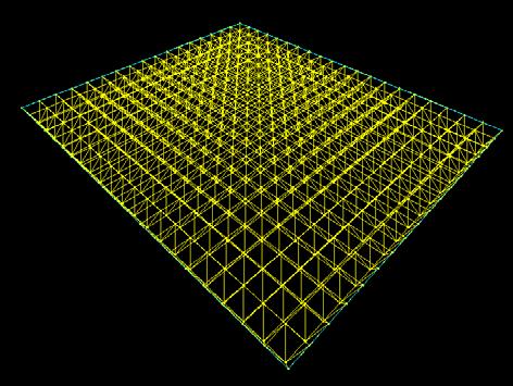
28 Figure 28 - Space Frame with 8-0 Modules and 8-0 Depth with Supporting Columns The space frame design with 8-0 modules and depth of 8-0 was analyzed further in SAP2000 by applying the appropriate dead, snow, and roof live loads to the frame. Loads were applied as concentrated loads to the joints of the space frame. The final design resulted in 760 top members that were each 8-0 long, 684 bottom members that were also each 8-0 long, and 1,444 diagonal members that were each nearly 10-0 long. This resulted in a total of 2,888 members and 23,104 linear feet of steel for the entire space frame. In addition, this configuration contained roughly 3,000 joints. Using the AISC Steel Construction Manual, it was found that an HSS4.000x0.291 (12.3 lb/ft) would work for the largest resulting compressive force and 10-0 unbraced length. From this result, a rough estimate of the weight of the space frame was made assuming an average of 10 lb/ft for all members. This resulted in a total weight of 231,040 lb for the space frame [(23,104 ft)(10 lb/ft) = 231,040 lb]. Therefore, the steel space frame required roughly five times as much steel, by weight, than the steel king post truss system with trusses spaced 30-0 o.c. Overall, the space frame weighed about psf while the steel king post truss system weighed about 2.39 psf. 28


29 Figure 29 - Image from SAP2000 Showing Axial Forces for Space Frame with 8-0 Modules and 8-0 Depth (red indicates higher axial forces) Figure 30 Additional Image from SAP2000 of Space Frame with 8-0 Modules and 8-0 Depth 29


30 Figure 31 Additional Image from SAP2000 of Space Frame with 8-0 Modules and 8-0 Depth Figure 32 Additional Image from SAP2000 of Space Frame with 8-0 Modules and 8-0 Depth 30
31 All space frame designs that were investigated for the natatorium were basically flat. A curved space frame would have been more architecturally appealing, especially for the roof shape from the exterior of the building. However, this would have driven up costs even more due to a more complex configuration. The flat space frame with 8-0 modules and 8-0 depth would have been too expensive in the first place due to the excessive number of joints required. This design weighed nearly three times as much as the original truss system, which weighed approximately 84,000 lb and went over budget in the first place. A space frame with 4-0 modules would have had even more joints than the design with the 8-0 modules. As mentioned before, using 12-0 modules seemed almost too large for the indoor pool space, although this would have resulted in fewer joints. Overall, the space frame design would have been too expensive for the. Plus, the less costly flat space frame configuration with no curves was rather plain architecturally and would have resulted in a basic flat roof shape when viewed from the exterior. Although space frames offer many advantages, they are generally quite expensive and are not very cost effective unless absolutely needed. Glulam Trusses The final roof system that was designed for the consisted of wood trusses. It was determined that using glulam members would be most appropriate due to the long span and rather large resulting forces in the members. It was also recognized early in the design process that trying to maintain the 30-0 truss spacing of the original design was unrealistic and resulted in extremely high loads for wood members. The first wood truss designs were analyzed at a 15-0 spacing and then a 10-0 spacing, which still resulted in high, but manageable, forces in the members. With the trusses at a spacing of 10-0 or 15-0, the column locations of the original design would still not have to change since they were spaced at 30-0 o.c. The trusses that would not directly land on a column would bear on a beam spanning between the columns. However, it was later determined that using trusses spaced at 8-0 o.c. would work best since 8-0 is a more common dimension in wood construction for components such as roof boards. Any possible way to make the construction process easier would help alleviate the overall cost of the project. The smaller spacing also helped by reducing the member forces. One of the drawbacks of using the 8-0 spacing was that the locations of the columns on which the east ends of the trusses bear had to move. This required that rooms on the ground floor and concourse level be properly laid out to accommodate the new column locations. Please see the Architectural Breadth for the column relocation study. It was decided that the truss members would be designed using Southern Pine glulam ID #50. Southern Pine is one of the best species of wood for pressure treatment because it absorbs the pressure treatment fluid better than other species of wood. Pressure treatment will be required for the wood trusses due to the harsh natatorium environment and is discussed in more detail in the M.A.E. Breadth, which is a continuation of the Building Enclosure breadth using information from AE 537. Southern Pine glulam ID #50 also 31
32 has rather high strength characteristics, which was deemed to be beneficial for the high anticipated member loads. Several sketches were made of various truss configurations, and these were later modeled in SAP2000. Loads that were applied to the top chord of the truss included the weight of laminated wood decking as well as other roofing dead loads, snow loads, and roof live load. A distributed dead load of 10 psf was applied to the bottom chord as well to account for the weight of speakers and any lighting fixtures mounted to the bottom chord. The appropriate loads were applied to the models in SAP2000, and the program was used to obtain the resulting member axial forces. The 2005 National Design Specification for Wood Construction was used to design the members. Resulting member forces, load combinations, and member design calculations are found in Appendix A. Figure 33 - Preliminary Sketch of Potential Wood Truss Configuration The first truss configurations that were designed had shapes much like those of the steel king post trusses that were designed. However, as was determined with the king post truss system, these configurations lacked much architectural style. Trusses were designed using a large depth of 20-0 to help minimize the axial forces in the top and bottom chords, especially since the members were going to be wood. Even with the 20-0 depth, the resulting member forces were still very high due to the span. The initial wood truss designs were modified by adding in more and more web members to reduce the extensive unbraced lengths of the top chord and to add more of a curved shape to the roof. Truss designs that were investigated are shown below in Figures 34 to 40. Trusses were initially designed at a spacing of 10-0 o.c., which resulted in an average force in the top and bottom chords of 45,000 50,000 lb each. Members for the final selected truss shape, which separated the top chord into ten members, were designed using sawn lumber and glulam members for a preliminary comparison of which of the two would be best for the trusses. Designing using sawn lumber resulted in either a 6x8 or 4x10 Select Structural Southern Pine bottom chord and either an 8x12 No. 1 Southern Pine, 8x10 Dense Select Structural Southern Pine, or 6x24 Dense Select Structural Southern Pine top chord. Due to the large sizes and small chance of finding members of 32
33 these sizes and required lengths, it was determined that designing using glulam members would be the best option. Loads Applied to Top Chord of Glulam Trusses DEAD PSF Zinc Standing Seam Metal Roof Panels 1.5 1/2" Moisture Resistant Gypsum Board /2" Rigid Insulation " Decking 7.6 Superimposed 5 Assumed Self Weight 5 Total Use 30 LIVE L r 20 SNOW S 23.1 Table 1 - Loads Applied to Top Chord of Glulam Trusses Figure 34 - Wood Truss Configuration with Top Chord Separated Into 6 Members Figure 35 - Modified Wood Truss Configuration with Top Chord Separated Into 6 Members 33
34 Figure 36 - Another Modified Wood Truss Configuration with Top Chord Separated Into 6 Members Figure 37 - Another Modified Wood Truss Configuration with Top Chord Separated Into 6 Members (Curved Shape is Slightly Different than Previous Design) Figure 38 - Wood Truss Configuration with Top Chord Separated Into 8 Members 34


35 Figure 39 - Wood Truss Configuration with Top Chord Separated Into 10 Members Figure 40 - SAP2000 Model of Glulam Truss Configuration with Top Chord Separated Into 8 Members The final glulam truss configuration with trusses spaced at 8 o.c. resulted in a bottom chord tensile axial force of approximately 50,000 lb and a top chord compressive axial force that was also about 50,000 lb. These were rather high forces, even with the trusses at the smaller 8-0 o.c. spacing. All truss members were designed to be the same width so that bolted metal side plates could easily be attached to the sides of the members. It was determined that bolted metal side plates would be the best option for connecting members of this size and for the high loads being transferred being the members. The final glulam truss design resulted in a 6 ¾ x 12 3/8 top chord, a 6 ¾ x 8 ¼ bottom chord, 6 ¾ x 6 7/8 web members, and 6 ¾ x 15 1/8 columns supporting the west ends of the trusses. Calculations are found in Appendix A. Design of the wood columns is discussed in the next section. All members are Southern Pine glulam ID #50. The bottom chord is spliced at three locations, which breaks up the bottom chord into four members. The top chord is broken up into ten individual members, so connections are 35


36 required at each joint where the top chord members meet. Web members also connect into each of these joints. The trusses bear on glulam columns on the west side and will bear on a concrete moment frame on the east side. The design of connections and of the concrete moment frame is discussed in later sections. Figure 41 - SAP2000 Model of the Final Selected Glulam Truss Configuration SUMMARY Top Chord 6 3/4" x 12 3/8" Bottom Chord 6 3/4" x 8 1/4" Web Members 6 3/4" x 6 7/8" West Column 6 3/4" x 15 1/8" All members are Southern Pine, Glulam I.D. #50 Table 2 - Summary of Member Sizes of Final Glulam Truss Configuration Figure 42 - Final Glulam Truss Configuration 36
37 The glulam truss system was generally found to be a more cost effective solution than the steel space frame and more architecturally pleasing than both the steel space frame and the steel king post truss system. The main problem encountered later in the design process was determining how the trusses would be transported to the job site. The 20-0 depth at the midspan of the truss made this section too large to be transported on the road since it would not clear any overpasses or else would be imposing on other traffic lanes if laid diagonally. The wood trusses would be cheaper if they are able to be fabricated offsite. If designed again it may be beneficial to look into using a shallower depth for the trusses if transportation becomes a problem. Figure 43 - Member Labels for Final Glulam Truss Final Glulam Truss Member Lengths Member # Length Member # Length 1 40'-0" 17 15'-1" 2 32'-6" 18 13'-2 11/16" 3 32'-6" 19 18'-6 1/2" 4 32'-6" 20 17'-0 7/16" 5 32'-6" 21 21'-5 3/16" 6 15'-1" 22 19'-3 3/16" 7 14'-1 3/4" 23 23'-2 15/16' 8 13'-6 9/16" 24 20'-0" 9 13'-2 1/4" 25 23'-2 15/16' 10 13'-0 1/4" 26 19'-3 3/16" 11 13'-0 1/4" 27 21'-5 3/16" 12 13'-2 1/4" 28 17'-0 7/16" 13 13'-6 9/16" 29 18'-6 1/2" 14 14'-1 3/4" 30 13'-2 11/16" 15 15'-1" 31 15'-1" 16 7'-7 3/4" 32 7'-7 3/4" Table 3 - Final Glulam Truss Member Lengths (Coordinated with Figure Above) 37
38 Comparison The three roofing systems that were investigated were compared in terms of cost, feasibility, and architectural impact. As mentioned above, the steel space frame system was determined to be a costly system for the. An estimation showed that the space frame weighted approximately three times as much as the original truss system and about five times as much as the alternate steel king post truss system. It also lacked architectural integrity due to the fact that a flat design had to be implemented in order to keep costs relatively low. Even with the plain, flat roof design, the cost would still be too high due to the excessive number of required members and connections. The steel king post truss system was expected to be lower in cost than the original design since the king post trusses had a much simpler configuration than the curved and tapered HSS trusses used in the original design. However, the king post truss system was too plain and, like the space frame system, did not provide much architectural freedom. The glulam truss system was determined to be the best option for the alternate roof system in terms of cost, feasibility, and architectural impact. With this system it was possible to develop a truss configuration with a nicely shaped curve without causing the cost of the system to skyrocket. The glulam truss system would also provide a relatively competitive cost compared to the steel king post truss system. Labor costs with wood construction are usually relatively low. Also, since the east ends of the trusses bear on the concrete moment frame, this eliminated the need for additional footings at this location. However, additional footings will be required under the columns that support the west ends of the trusses since the number of trusses was increased from 5 in the original design to 19 in the alternate glulam truss design. These footings may be much smaller than those used to support the west ends of the originals trusses and truss columns, although they are greater in number. Further analysis is required to compare footings costs. Overall, the glulam truss system best met the goals of this thesis by providing a pleasing architectural appearance but keeping costs reasonable by not getting too fancy. Comparison of Three Alternate Roof Systems Cost Feasibility Architectural Impact Steel King Post Trusses Competitive High Poor Steel Space Frame High Poor/Moderate Poor/Moderate Glulam Trusses Competitive High High Table 4 - Comparison of the Three Alternate Roof Systems that were Investigated The glulam truss system was compared to the original design in terms of cost using RS Means Building Construction Cost Data (2009). A summary of the estimated costs are shown below in Tables 5 and 6. It was estimated that the new glulam truss wood system would be approximately $100,000 cheaper than the original steel truss system. The trusses themselves were estimated to be nearly the same cost, but the laminated deck was found to be much less costly than the long-span metal roof deck used in the original design. The weight of the glulam truss roof system was determined to be about 544 kips, while the roof structural system of the original design was about 257 kips. While the weight of the roof structural system more than doubled, the glulam truss roof system was 38
39 still found to cost less than the original roof system. The glulam trusses also would have most likely been cheaper had curved top chord members been used. This would have eliminated the required number of splice connections for the top chord by maybe separating the top chord into three or four members instead of ten. These tables also include the estimated costs of the new concrete moment frames and the original steel moment frames. The concrete moment frames are discussed in more detail in a later section. The cost estimation comparison only takes into account the parts of the building that changed, which was the roof structural system and the replacement of steel braced frames with concrete moment frames. The additional cost of the wood braced frames that were added was not included in this comparison. The design of these braced frames is discussed in a later section. This comparison does not take into account the cost of the moment connections for the original system nor any bolts or connections that were required for the original design. Also, weight per linear foot values for HSS18x18x5/8 shapes could not be found in the AISC Steel Construction Manual, so the weight of an HSS16x16x5/8 was used instead. Therefore, the estimated cost of the original system will be slightly higher than that calculated. The cost of special wood connections that may be required for the wood lateral system may be expensive and were not taken into account as well. Calculations for the cost comparison are found in Appendix A. Estimated Cost Comparison Cost ($) Wood Roof System Metal Side Plates 14, Laminated Roof Deck 113, Plywood Sheathing 17, Glulam Trusses 242, High-Strength Bolts 148, TOTAL 536, Steel Roof System (Original Design) Galvanizing of Trusses 15, Galvanizing of Metal Roof Deck 35, Metal Roof Deck 369, Steel Trusses 250, TOTAL 670, Concrete Moment Frames Formwork for Beams 22, Formwork for Columns 11, Columns 39, Beams 77, Reinforcing for Beams 23, Reinforcing for Columns 9, TOTAL 184, Steel Moment Frames (Original Design) Beams 56, Columns 45, Moment Connections TOTAL 102, Table 5 - Estimated Costs of Alternate Design versus Original Design 39

40 Total Overall Estimated Costs Cost ($) Alterntate Structural System TOTAL 720, Original Structural System TOTAL 772, Table 6 - Total Overall Estimated Costs of Alternate Design versus Original Design Wood Decking Wood structural panels, such as plywood, are usually used to span between closely spaced roof beams or trusses. Lumber sheathing is used to span longer distances. Due to the 8-0 spacing of the glulam trusses, lumber sheathing was required for this alternate design. Lumber sheathing is available as solid decking or laminated decking. It was determined that laminated decking would be more cost effective if 3 or thicker decking is required. Nominal three and four inch decking is adapted well for use with glued laminated arches or trusses and can provide a pleasant all-wood appearance. The decking can also be erected quickly and easily. Timber decking can span from 3 20 feet, and the layup of the decking affects its capacity. Shown below are diagrams from WCD 2 Tongue and Groove Roof Decking showing typical layups of tongue-and-groove decking. Figure 44 WCD 2: Tongue and Groove Roof Decking Figure 45 - Simple Span Layup (Image from WCD 2 Tongue and Groove Roof Decking) 40
41 Figure 46 - Cantilevered Pieces Intermixed Layup (Image from WCD 2 Tongue and Groove Roof Decking) Figure 47 - Combination Simple and Two-Span Continuous Layup (Image from WCD 2 Tongue and Groove Roof Decking) Figure 48 - Two-Span Continuous Layup (Image from WCD 2 Tongue and Groove Roof Decking) First the required thickness of heavy timber, or solid, roof decking was determined. Load tables from AITC 112*-81 Standard for Tongue-and-Groove Heavy Timber Roof Decking were used to determine the required thickness of decking. Table 3 from this Standard gives bending stress values and modulus of elasticity values for various species of wood to be used with the load tables. Southern Pine was selected to be used to match the Southern Pine trusses. Since the decking would be used where the moisture content will exceed 19% for an extended period of time, bending stress values were multiplied by a factor of 0.86 and modulus of elasticity values by a factor of A two-span continuous layup was chosen for the decking. For nominal two inch decking, the 41
42 allowable roof load was limited by deflection. It was determined that nominal two inch decking would barely work for the two-span continuous layup. The two-span continuous layup has the highest capacity out of all the layups. The allowable roof load to meet the L/240 deflection criteria for this layup is psf. The appropriate C D factor must be applied to the given values for different load combinations. For the load combination D + L r, the value of psf will apply since C D = 1.0 for this load combination. The total load from the controlling load combination D + L r was 50 psf, which works but is very close to the allowable deflection limit. Therefore, it was decided that nominal three inch decking should be provided due to any possible uncertainties in the calculated loads. The required nailing schedule for three and four inch decking is given from this AITC Standard as follows: Each piece should be toenailed at each support with one 40d nail and face nailed with one 60d nail. Courses shall be spiked to each other with 8 in. spikes at intervals not to exceed 30 in. through predrilled edge holes and with one spike at a distance not exceeding 10 in. from each end of each piece. Calculations are found in Appendix A. Next, the required thickness of laminated decking was determined. Span-load tables from Section 7 of the Timber Construction Manual were used. Table 7.9 from this Section provided values for Southern Pine, so Southern Pine was again selected as the species for the decking. This table gave allowable uniformly distributed total roof load values limited by deflection for controlled random layup decking. The smallest size given for Southern Pine, with an actual size of 2 3/16 x 5 3/8, had a capacity of 136 psf for the deflection limit of L/240. The actual load for the controlling load combination of D + L r was well within this limit. The footnotes at the bottom of the table also state that the actual size for Southern Pine is 2 ¼ x 5 3/8. Therefore, it was determined that nominal three inch Southern Pine laminated decking would be used with an actual size of 2 ¼ x 5 3/8. In addition, it was decided that the laminated decking would be used instead of the heavy timber, or solid, roof decking. The Southern Pine laminated decking would better match the appearance of the Southern Pine glued-laminated trusses. Plus, the laminated decking would generally be cheaper than solid decking due to the thicker required decking size. Diaphragm It is sometimes difficult or costly to obtain diaphragm action from three inch tongue-andgroove decking alone. Sometimes adhesives can be applied on top of the tongue-andgroove joints to help achieve diaphragm resistance. Certain nailing schedules can also be applied to the tongue-and-groove joints, but this can result in increased labor costs. The most common method to obtain diaphragm action when using three inch tongue-andgroove decking is to install plywood or another structural panel over the decking. The decking provides the required blocking, and the requirements for nailing of panel edges basically stay the same as if the panels were being installed over joists. For this design, plywood was designed to provide diaphragm resistance and would be nailed on top of the tongue-and-groove decking. ANSI / AF&PA SDPWS-2005 Special Design Provisions for Wind and Seismic was used to determine the required thickness of plywood for the 42
43 design wind and seismic loads applied to the building. The required thickness for seismic loads was found to govern. The final design consisted of 3/8 Structural I plywood with all edges supported and nailed into three inch minimum nominal framing, 8d common nails at 6-in. o.c. at boundary and continuous panel edges, 6-in. o.c. at other panel edges (blocking is provided by the tongue-and-groove decking), and 12-in. o.c. in the field. Calculations are found in Appendix A. Chords were also designed for the required diaphragm forces. The axial forces in the chords were determined by resolving the diaphragm moment into a couple for both the longitudinal direction and the transverse direction. For the longitudinal direction, the wood members at the top of the braced frames were designed to function as the chord members. Seismic loads controlled the design and resulted in a 3 ½ x 5 ½ member using Southern Pine glulam ID #50. For the transverse direction, the wood members at the top of the braced frames in the North/South direction were designed to act as the chord members. Seismic loads also controlled the design of these members, which resulted in 6 ¾ x 8 ¼ members using Southern Pine glulam ID #50. Wood Columns The columns supporting the west end of the trusses were steel in the original design. For the alternate wood design, it was decided that glulam columns would be used to match the glulam roof trusses. The columns were designed to take all the roof loads, although SAP2000 models showed that a large portion of this load was carried by the braces. The columns were also designed to take lateral wind loads that were applied to the west façade. The columns were assumed to be pinned at the top and bottom, and the resulting moment due to wind load was rather large due to the 40-0 unbraced length of the column. The design resulted is 6 ¾ x 15 1/8 columns using Southern Pine glulam ID #50. Calculations for the design of the glulam columns are found in Appendix A. Wood Truss Member Connections Bolted metal side plate connections were designed to connect the members of the glulam trusses. This was considered to be the best design option due to the large member forces in the top and bottom chord. Connections were designed using the 2005 National Design Specification for Wood Construction. The load combination D + L r controlled all connection designs. Connections were designed using ¼ steel side plates. Nominal design values for ¾ bolts in double shear for a 6 ¾ thick Southern Pine glulam member with ¼ steel side plates and load applied parallel to grain were provided in Table 11I of the NDS. A wet service factor of 0.7 was applied to the connection designs due to the high moisture levels in the natatorium. All edge distance, end distance, and spacing requirements were met for all connections to obtain a geometry factor of one. Bottom chord heel connections and splice connections both resulted in (24) ¾ diameter bolts arranged in two rows. The spacing between bolts in a row was 3, and the spacing between rows of bolts was 2 7/8. Six inch steel plates were used to architecturally allow 43
44 a portion of the glulam members to be seen around the edges of the plates instead of making the plates cover the entire depth of the bottom chord. Due to the large number of required bolts for the top chord and bottom chord connections, the use of 4-inch diameter shear plate connectors was investigated. However, the design resulted in a required fifteen 4-inch diameter shear plates using a geometry factor of 1.0, which requires a 9 spacing between the shear plates in a row for parallel to grain loading. This would result in an unrealistically large connection. Therefore, the final connection used the (24) ¾ diameter bolts arranged in two rows. Figure 49 - Typical Bottom Chord Splice Connection Top chord connections resulted in (28) ¾ diameter bolts arranged in two rows. These connections were designed for the highest top chord force, and the same connection was used for all top chords. The forces in the top chords were all relatively close in magnitude, so it was valid to use the same connection for all top chord connections. Plus, this would create a more pleasing architectural appearance if all of these connections are the same. Eight inch steel plates were used instead of six inch plates due to the larger depth of the top chord. Architecturally, it was desired to keep approximately the same percentage of wood clearance around the edges of the plates as that for the bottom chord connections. Figure 50 - Typical Top Chord Connection 44
45 The resulting axial forces in the web members were very small compared to the forces in the top and bottom chord. All forces in the web members were around 1,000 lb or less. Therefore, this permitted the use of (1) ¾ diameter bolt connections to connect the web members to the chords. Several sources suggest using overlapping plates at connections such as this to essentially maintain a pinned connection, but a single plate for the entire connection was chosen for this design. The use of full single plates is also more common and has a more appealing appearance architecturally. Figure 51 - Typical Vertical Web Member Connection to Bottom Chord Figure 52 - Typical Web Member Connection to Bottom Chord 45
46 Figure 53 - Top Chord Connection More advanced connections may be required at the heel connections where the trusses and braces in the North/South direction meet at the top of the wood columns. Special saddle-type connections may need to be investigated in which the truss would rest in the saddle while lateral bracing members can frame into the sides of the glulam column by steel angles. All members would most likely be bolted. Wood Truss Connection to Concrete Moment Frame at Column Line 2 The east ends of the steel trusses of the original design for the Farquhar Park Aquatic Center were supported by steel HSS columns. The east ends of the glulam trusses of the alternate design must frame into the new concrete moment frame at column line two. The design of this moment frame is discussed in more detail in a later section. All lateral forces perpendicular to and parallel to the moment frame that are to be resisted by the frame must be properly transferred from the roof diaphragm to the concrete moment frame. A typical connection detail is shown below. Lateral forces perpendicular to the moment frame are transferred from the wood plate to the concrete beam or concrete column by anchor bolts. The same occurs for lateral forces parallel to the concrete moment frame. The strength of the anchor bolts is governed by the capacity of the bolt parallel to grain or perpendicular to grain in the wood plate, or by its capacity in the concrete. 46
47 Figure 54 - Typical Connection of Glulam Truss to Concrete Beam or Column of Concrete Moment Frame at Column Line 2 47
48 Lateral System Study Wind Loads Method 2 Analytical Procedure of ASCE 7-05 Section 6.5 was used to determine wind loads. Wind loads had to be re-calculated from those used in Technical Report 3 due to changes in the building height and changes in the applicable wind load equations due to the switch from steel moment frames to concrete moment frames at column lines one and two. Although the updated wind loads resulted in lower wind pressures as compared to those from the Technical Report 3, the base shear in the North/South direction slightly increased due to the larger wall surface area that resulted from the glulam truss configuration. The tops of the columns along column line 2 were also raised from about 37-0 to 40-0 above ground level, which added surface area to the North and South facades. The base shear in the East/West direction for the alternate design was considerably less than that from Technical Report #3 due to the change in roof shape. The curved roof shape using the glulam trusses resulted in wind uplift loads on the roof, while the original design had to account for horizontal wind load for basically the entire height of the building due to the nearly vertical west wall. Variables used in the wind calculations are located in Table 7 and wind loads are noted in Tables 8, 9, and 10. Calculations for wind loads are found in Appendix B. Wind Variables ASCE 7-05 Reference Basic Wind Speed V 90 mph Figure 6-1 (p. 33) Wind Directionality Factor K d 0.85 Table 6-4 (p. 80) Importance Factor I 1.15 Table 6-1 (p. 77) Exposure Category C Sec Topographic Factor K zt 1.0 Sec Velocity Pressure Exposure Coefficient Evaluated at Height z K z Varies Table 3 (p. 79) Velocity Pressure at Height z q z Varies Eq Velocity Pressure at Mean Roof Height h q h Eq Equivalent Height of Structure z 36 Table 6-2 Intensity of Turbulence I z Eq. 6-5 Integral Length Scale of Turbulence L z ' Eq. 6-7 Background Response Factor (North/South) Q Eq. 6-6 Background Response Factor (East/West) Q Eq. 6-6 Gust Effect Factor (North/South) G Eq. 6-4 Gust Effect Factor (East/West) G 0.85 Eq. 6-4 External Pressure Coefficient (Windward) C p 0.8 Figure 6-6 (p. 49) External Pressure Coefficient (N/S Leeward) C p -0.5 Figure 6-6 (p. 49) External Pressure Coefficient (E/W Leeward) C p Figure 6-6 (p. 49) Table 7 - Wind Variables 48
49 Level Height Above Ground Story Height (ft) K z "Building 1" - Wind Loads (North/South Direction) B=183'-0", L=156'-0" Wind Pressure (psf) Force (k) Story Total Force (k) of q z Pressure WindwardLeeward Side Shear of Total Roof Windward Windwar Walls (psf) Pressure - z (ft) Only d (k) sum(story Shear (Windward))=89.78 k sum(moment (Windward))= ft-k sum (Story Shear (Total))= k sum (Moment (Total))= ft-k Story Shear Total (k) Table 8 - Wind Loads to Indoor Pool Area N/S direction (these loads are applied to the braced frame at column line 1 and the moment frame at column line 2) *Wind load at Level 4 gets applied to Level 3 for lateral force resisting system Moment Windward (ft-k) Moment Total (ft-k) Figure 55 - Building 1 Wind Loads North/South Floor Height Above Ground Story Height (ft) K z "Building 4" - Wind Loads (North/South Direction) B=183'-0", L=156'-0" Wind Pressure (psf) Force (k) Story Total Force (k) of q z Pressure WindwardLeeward Side Shear of Total Roof Windward Windwar Walls (psf) Pressure - z (ft) Only d (k) sum(story Shear (Windward))=8.41 k sum(moment (Windward))= ft-k sum (Story Shear (Total))=14.21 k sum (Moment (Total))= ft-k Story Shear Total (k) Table 9 - Wind Loads to Lobby Area N/S direction (these loads are applied to the moment frame at column line 2 and the moment frame at column line 4) Moment Windward (ft-k) Moment Total (ft-k) Figure 56 - Building 4 Wind Loads North/South 49
50 Floor Height Above Ground Story Height (ft) - z (ft) Only d (k) sum(story Shear (Windward))=69.50 k sum (Story Shear (Total))= k sum(moment (Windward))= ft-k Wind Loads (East/West Direction) B=156'-0", L=183'-0" Wind Pressure (psf) Force (k) Total Force (k) of Pressure of Total Roof Windward (psf) Pressure K z q z WindwardLeeward Side Walls Story Shear Windwar sum (Moment (Total))= ft-k Story Shear Total (k) Moment Windward (ft-k) Table 10 - Wind Loads to Entire Building E/W direction (these loads are applied to the perimeter braced frames in the E/W direction) Moment Total (ft-k) Figure 57 - Wind Loads on Entire Building (East/West) Seismic Loads Seismic loads were determined using ASCE Seismic loads had to be recalculated for the alternate design due to changes in the weight of the building. The weight of the glulam truss roof system was considerably heavier than the original steel roof structure, and the weight of the concrete moment frames was much heavier than the weight of the original steel moment frames. Values of R and C s also changed due to changes in the building s lateral force resisting systems. For Technical Report 3, an R-value of 3 was used for Steel systems not specifically detailed for seismic resistance, excluding cantilever column systems. For the wood braced frames of the alternate design, an R- value of 4 was used for Light-framed wall systems using flat strap bracing, which was the closest category from Table (ASCE 7-05) that applied. For the concrete moment frames, an R-value of 3 was used for Ordinary Reinforced Concrete Moment Frames. After performing the seismic load calculations, it was determined that the C s value for the wood braced frames was higher than the C s value for the concrete moment frames. Therefore, the higher, more conservative C s value was applied to all lateral force resisting frames throughout the entire building. Variables used in the seismic calculations are located in Table 11 and seismic loads are noted in Tables 13, 14, 15, and 16. Calculations for seismic loads are found in Appendix B. 50
51 Site Classification Occupancy Category Seismic Design Variables C III ASCE Reference Steel Systems Not Specifically Detailed for Structural System Seismic Resistance, Table Excluding Cantilever Column Systems Spectral Response Acceleration, Short Period S S 0.2 Figure 22-1 Spectral Response Acceleration, 1-Second Period S Figure 22-2 Site Coefficient F a 1.2 Table Site Coefficient F v 1.7 Table MCE Spectral Response Acceleration, Short Period S MS 0.24 Eq MCE Spectral Response Acceleration, 1-Second Period S M Eq Design Spectral Acceleration, Short Period S DS 0.16 Eq Design Spectral Acceleration, 1-Second Period S D Eq Seismic Design Category SDC A Table Response Modification Coefficient R 3 Table Importance Factor I 1.25 Table Approximate Period Parameter C t 0.02 Table Building Height (above grade) h n 60 ft Approximate Period Parameter x 0.75 Table Approximate Fundamental Period T a Eq Long Period Transition Period T L 6 sec Figure Calculated Period Upper Limit Coefficient C u 1.7 Table Fundamental Period T Seismic Response Coefficient C s Eq Structure Period Exponent k 1.0 Table 11 - Seismic Design Variables Level Elevation 3 40'-0" 2 24'-8" 1 10'-6" Table 12 - Elevations Corresponding to the Levels Used in the Lateral Analysis 51
52 Building 1 Building 1 - Level 1 Weights of Building Components Center of Mass Component Weight x (ft) y (ft) Large Truss Columns kips Wind Columns kips Precast Concrete Panels kips Total= kips Building 1 - Level 2 Weights of Building Components Center of Mass Component Weight x (ft) y (ft) Large Truss Columns kips Wind Columns kips Conc. Moment Frame at C.L kips Precast Concrete Panels kips Precast Concrete Sills kips Total= kips Building 1 - Level 3 Weights of Building Components Center of Mass Component Weight x (ft) y (ft) Large Wood Truss Columns kips Large Wood Trusses kips Wind Columns kips Conc. Moment Frame (C.L. 2) kips Roofing kips Total= kips
53 Seismic Loads - "Building 1" Level Story Height h x k k Lateral Story Moments h Weight w x (ft) x w x h x C vx Force F x Shear V x M x (ft-k) sum(w x h k x )= sum(f x )=V= kips sum(m x )= Total Weight of "Building 1" (Above Grade) = kips Table 13 - Seismic Loads Building 1 *Seismic force at Level 4 is applied to Level 3 for lateral force resisting system V = CsW = ( )( kips) = kips C vx = w x h x k /sum(w i h i k ) Figure 58 - Building 1 Seismic Loads 53
54 Building 2 Building 2 - Level 1 Weights of Building Components Center of Mass Component Weight x (ft) y (ft) Concrete Grandstand kips (2) Stairs at Grandstand kips Concrete Beams (Bent and Sloped) kips Balcony kips Conc. Moment Frame (C.L. 1.8) kips Total= kips Building 2 - Level 2 Weights of Building Components Center of Mass Component Weight x (ft) y (ft) Concrete Grandstand kips Interior Walls kips Total= kips Seismic Loads - "Building 2" Level Story Height h x k k Lateral Story Moments h Weight w x (ft) x w x h x C vx Force F x Shear V x M x (ft-k) sum(w x h k x )= sum(f x )=V= kips sum(m x )= Total Weight of "Building 2" (Above Grade) = kips Table 14 - Seismic Loads Building 2 V = CsW = ( )( kips) = kips C vx = w x h x k /sum(w i h i k ) Figure 59 - Building 2 Seismic Loads 54
55 Building 3 Building 3 - Level 1 Weights of Building Components Center of Mass Component Weight x (ft) y (ft) Precast Concrete Planks kips Concrete Stairs and Landing (North) kips Concrete Stairs and Landing (South) kips Precast Concrete Ramp kips Interior Walls from Ground Level kips Interior Walls from Level kips Total= kips Seismic Loads - "Building 3" Level Story Height h x k k Lateral Story Moments h Weight w x (ft) x w x h x C vx Force F x Shear V x M x (ft-k) sum(w x h k x )= sum(f x )=V= kips sum(m x )= Total Weight of "Building 3" (Above Grade) = kips Table 15 - Seismic Loads Building 3 V = CsW = ( )( kips) = kips C vx = w x h x k /sum(w i h i k ) Figure 60 - Building 3 Seismic Loads 55
56 Building 4 Building 4 - Level 2 Weights of Building Components Center of Mass Component Weight x (ft) y (ft) Roofing Above Lobby kips Trusses Above Lobby kips Gallery Level Framing kips Canopy Framing kips Columns in Lobby kips Precast Concrete Panels kips Mechanical Unit Support Framing kips Mechanical Units kips kips Seismic Loads - "Building 4" Level Story Height h x k k Lateral Story Moments h Weight w x (ft) x w x h x C vx Force F x Shear V x M x (ft-k) sum(w x h k x )= sum(f x )=V= kips sum(m x )= Total Weight of "Building 4" (Above Grade) = kips Table 16 - Seismic Loads Building 4 V = CsW = ( )( kips) = kips C vx = w x h x k /sum(w i h i k ) Figure 61 - Building 4 Seismic Loads 56
57 Distribution of Loads Since the diaphragm above the indoor pool area for the alternate design was wood, the diaphragm was considered to be a flexible diaphragm. With flexible diaphragms, loads are distributed based on tributary area. Therefore, for lateral loads applied to the large indoor pool area ( Building 1 ) in the North/South direction, half of these loads were distributed to the wood braced frame at column line 1 and the other half of these loads was distributed to the concrete moment frame at column line 2. For lateral loads in the East/West direction, each of the five concrete moment frames in the East/West direction received loads based on tributary area. Since these frames were evenly spaced, the load distributed to each frame was almost the same. Small differences in load occurred at the outer columns. Due to symmetry, the two perimeter wood braced frames in the East/West direction each received a much smaller load than that applied to the concrete moment frames. Although the roof above the indoor pool area became a flexible diaphragm, the roof above the main lobby remained a rigid diaphragm. With a rigid diaphragm, loads are distributed based on the relative stiffnesses of the lateral force resisting frames. Wood Braced Frame at Column Line 1 A wood braced frame at column line 1 was designed as an alternate to the originally designed steel braced frames at the same location that were part of the tapered steel trusses that spanned over the indoor pool area. Wood was chosen for these frames to architecturally match the glulam trusses and laminated decking. Several braced frame configurations were designed and compared to determine the one that best suited the space architecturally. Frames with two, three, and four X-braces in elevation were considered. Various patterns of different locations of the X-bracing were also investigated and are shown below in Figures 62 to 65. The final selected configuration is shown below in Figure 66. Figure 62 - Potential Column Line 1 Braced Frame Configuration with 4 X-Braces Vertically 57

58 Figure 63 - Potential Column Line 1 Braced Frame Configuration with 3 X-Braces Vertically Figure 64 - Potential Column Line 1 Braced Frame Configuration with 3 X-Braces Vertically Figure 65 - Potential Column Line 1 Braced Frame Configuration with 4 X-Braces Vertically and Different Layout of Locations of Braced Frames 58

59 Figure 66 - Final Selected Braced Frame Configuration at Column Line 1 The final selected braced frame configuration consisted of ten braced frames that were spaced apart in an even pattern along column line 1 with two of the frames right beside each other in the middle. The main intent of the braced frames was to brace every column along column line 1. These columns were 40-0 high and already had to bracing in the East/West direction. If these columns were not braced in the North/South direction, the resulting column sizes would have been considerably large, especially since glulam was used for the columns. The columns were already 15 1/8 deep due to the 40-0 unbraced length in the East/West direction. The visual appearances of using two, three, and four X-braces in the vertical direction were also considered, and the three X- brace design was determined to be most appropriate for the space. This configuration provided a desirable height-to-width ratio of the X-braces, and the three level also match up very closely with the level of the other lateral force resisting frames used throughout the building. SAP2000 was used to model the new braced frame. All members of the braced frame were assumed to be pinned at the ends. The diagonal members are also connected where they intersect each other to reduce their unbraced length for bending about the y-axis from to 7.77, which helped to reduce the required member size. The controlling load combination D W S resulted in a maximum compressive force in the diagonal members of kips. A 3 ½ x 6 7/8 member using Southern Pine glulam ID #50 was calculated as having sufficient capacity for the diagonal members. This size was used for all diagonal members for ease of construction and architectural consistency. The diagonal members would be bolted to the glulam columns, but special brackets or attachment equipment may be necessary since these braced members are much thinner than the 15 1/8 face of the glulam column that they are framing into. Further investigation is required for these connections. Calculations for the design of the diagonal members are found in Appendix B. Concrete Moment Frame: Column Line 1.8 The steel moment frames along column line 1.8 and column line 2 were replaced by concrete moment frames in the alternate design. The proposal for this project stated that 59
60 this area of the building would be redesigned as completely precast, but it was not recognized at that time that it is not feasible to design moment frames using precast concrete. After speaking with John Jones of Nitterhouse Concrete Products, it was realized that moment connections with precast columns and beams are possible but are not very cost effective. Therefore, the concrete moment frames for the Farquhar Park Aquatic Center alternate system were designed using standard reinforce concrete instead of precast units. The columns along column line 1.8 do not take a great deal of axial force since they only really support one floor, although they support part of the concrete grandstand and concrete balcony in addition to the precast concrete planks at the concourse level. The columns do resist considerably high moments, however, which resulted in rather large column sizes. High moments were due to heavy floor dead and live loads and well as significant seismic loads since a majority of the weight of the building is located in this area. The superimposed live loads were high for the area that these concrete columns were supporting due to the mechanical room and grandstand live load. The self weight dead loads of the grandstand, balcony, and precast planks were also rather high. Pattern loading was considered and produced large moments in the exterior columns of the moment frame. Seismic loads created additional moments in the columns and beams. This moment frame does not resist wind loads. Columns and beams were designed using ACI PCA Column was also used to study interaction diagrams and check the capacity of the columns for the required axial forces and moments. Reinforced concrete column design aids from the textbook Reinforce Concrete Design and Mechanics by Wight and MacGregor were used as well. Calculations are found in Appendix B. The columns at column line 1.8 were found to not be slender, so the diagrams from PCA Column did not include slenderness. A clear cover of 2.25 was used instead of 1.5 due to the corrosive natatorium environment. The final design resulted in 24 x24 columns with (12) #8 bars and 24 x26 beams with (5) #8 bars and (5) #7 bars for negative-moment reinforcement and (5) #7 bars for positive-moment reinforcement. Story drifts due to seismic loads were determined to be well within the required limits and are found in Appendix B. The 24 x24 column size matched the width of the designed columns at column line 2 and the width of the sloped concrete beams. Details are shown below in Figures 67, 68, and 69. ACI Code Section requires that at least one-fourth of the positive-moment reinforcement used at mid-span must be continuous through interior supports and fully anchored at exterior supports. More detailed development, anchorage, and splicing requirements require further investigation. 60
61 Figure 67 - Concrete Moment Frame at Column Line 1.8 Figure 68 - Detail of Typical Reinforced Concrete Column at Column Line 1.8 Figure 69 - Detail of Typical Reinforced Concrete Beam at Column Line
62 Concrete Moment Frame: Column Line 2 The concrete moment frame along column line 2 was designed in the same manner as the frame along column line 1.8. High moments resulted in the beams and columns due to large roof loads and live loads applied to the frame. The glulam roof trusses spaced at 8 o.c. bear on the top concrete beams and the tops of the columns. The moment frame also carried about half of the self weight of the precast grandstand as well as superimposed loads applied to the grandstand. Live load patterns were also considered, which resulted in significant moments in the columns and beams. ACI was used to design the columns and beams. PCA Column was also used to produce interaction diagrams and check the capacity of the designed columns. Reinforced concrete column design aids from the textbook Reinforce Concrete Design and Mechanics by Wight and MacGregor were also used. A clear cover of 2.25 was again used due to the corrosive natatorium environment. Calculations are found in Appendix B. The design resulted in 24 x24 columns with (12) #8 bars and 24 x30 beams with (10) #7 bars for negative moment (8) #6 bars for positive moment. Story drifts due to wind and seismic loads were determined to be within the required limits. Seismic story drifts were well within the allowable limits while story drifts due to wind were close to the limit of H/400. Deflection limits due to wind loads were one of the main reasons why the columns had to be so large. Figure 70 - Concrete Moment Frame at Column Line 2 Concrete Moment Frame East/West Direction The original East/West lateral system design for the featured five steel moment frames with bent and sloped W27 beams spanning between column lines 1.8 and 2. The steel HSS trusses and supporting tapered columns also helped to resist lateral loads. For the alternate design, perimeter braced frames were originally going to be used to resist all lateral loads in the East/West direction. However, this design was susceptible to having uplift problems due to the significant resulting 62
63 lateral forces to be resisted by each frame and would have probably required large, complex, and expensive connections at the bases of the columns. Therefore, concrete moment frames were designed to resist lateral loads in the East/West directions. The five frames matched the configuration of the original steel moment frames in the East/West direction. Perimeter wood braced frames were also designed and are described in the next section. The concrete moment frames in the East/West direction consisted of sloped concrete beams spanning between the concrete columns designed at column line 1.8 and column line 2. Wind load and seismic loads were applied to the frame. The columns, which were already designed for lateral loads in the North/South direction, had to be checked for lateral loads in the East/West direction as well. The 24 x24 columns with (12) #8 bars were found to have sufficient capacity. The design of the sloped concrete beams resulted in 24 x26 beams with (7) #7 bars for negative-moment reinforcement and (4) #7 bars for positive moment reinforcement. Details are shown below in Figures 71 and 72. Story drifts for seismic loads were found to be well within the drift limits, but story drifts due to wind were very close to the H/400 limit. Again, deflection played a major role in requiring a large column size at column line 2. Figure 71 - Concrete Moment Frame in East/West Direction 63
64 Figure 72 - Midspan Detail of Typical Sloped Reinforced Concrete Beam of Moment Frame in East/West Direction Wood Braced Frames East/West Direction Wood braced frames were added along the North and South edges of the indoor pool area to help alleviate some of the lateral load applied by the East/West concrete moment frames. Due to the flexible wood roof diaphragm, lateral loads were distributed to the lateral force resisting frames based on tributary area. The frames did not take significant lateral loads, which was beneficial because it limited the size of the required members. In addition, gravity loads were neglected since most, if not all, of the gravity loads were carried by the glulam trusses. Architectural considerations were taken into effects when examining different configurations for the braced frames. The final configuration used two separate frames along both the North and South sides with three X-braces vertically for each frame as shown in Figure 73 below. Members were designed using Southern Pine glulam ID #50 to match the glulam trusses and braced frames in the North/South Direction at column line 1. The diagonal members were designed to be the same width as the columns for ease of bolted metal side plate connections. The 2005 National Design Specification for Wood Construction was used to design the members. The final design resulted in 6 3/4 x 6 7/8 Southern Pine glulam ID #50 members for all diagonal and horizontal members. The frames were very stiff and the story drifts were well within the limits for wind and seismic loads. 64
65 Wind Columns Figure 73 Elevation Showing Wood Braced Frames in East/West Direction The original design for the natatorium used steel HSS wind columns to transfer the lateral load in the North/South direction to the roof diaphragm. These wind columns were redesigned in wood to match the rest of the wood structural system in the indoor pool area. Wood wind columns are spaced at 26-0 o.c. as compared to the 20-0 spacing of the original steel wind columns. A total of ten wind columns were used, with the tallest being 60-0 to reach the top of the glulam trusses. The wind columns are used solely to transfer lateral loads to the roof diaphragm. The wood braced frames in the East/West direction frame into the outer or compression chord of the wind columns. A truss configuration was used to match the original design. Plus, using a single wood member to span 60-0 would have resulting in very high moments and thus very large required members. A model of the truss was created using SAP2000, and the appropriate lateral loads were applied. The 2005 National Design Specification for Wood Construction was used to design the members. The final design resulted in 6 ¾ x 6 7/8 Southern Pine glulam ID #50 members. The truss members may be connected together using toothed metal plate connectors. The wood braced frames in the East/West direction were designed so that the 6 7/8 dimension matched the 6 7/8 dimension of these wind column members for the use of bolted metal side plate connections. Calculations are found in Appendix B. Overturning Check The lateral forces applied to the building cause overturning moments at the bases of the lateral force resisting frames. These overturning moments cause tensile, or uplift, forces in members of the lateral force resisting frames. Wind uplift forces also contribute to these forces. The dead weight of the building, along with superimposed loads, resists these upward forces caused by the overturning moments. The worst case of overturning occurred at the wood braced frame in the East/West direction. Special connections at the bases of the wood braced frames may be required to resist overturning forces. A more detailed check of overturning effects at several locations was performed, and calculations 65

66 are found in Appendix B. Overturning at the concrete moment frame at column line 1.8 was not a concern because the frame only takes seismic loads, and the uplift force due to seismic loads was only about two kips. Overturning was not found to be a concern with any other lateral force resisting systems as well. Foundation Check The capacities of the foundations used in the original design for the Farquhar Park Aquatic Center must be checked accounting for the new weight of the building. The weight of the wood roof structure and concrete moment frames caused the overall building weight to increase. The capacity of a critical footing at column line 2 was checked and found to be more than sufficient to handle the increased loads of the building. Calculations are founding Appendix B. 3D Models 66
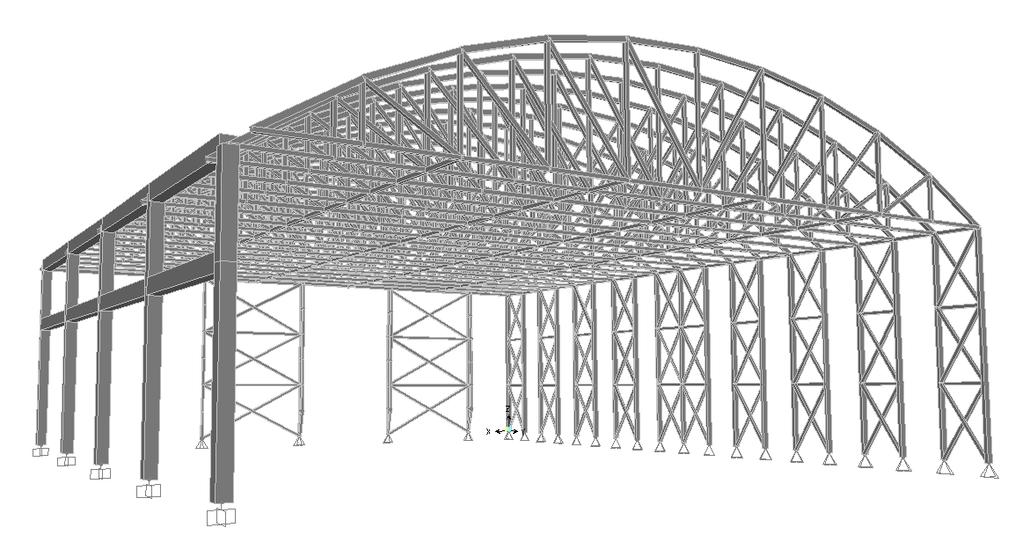
67 67
68 Architectural Breadth An architectural breadth was studied due to significant changes in the shape of the natatorium s roof and appearance of the façades. In addition, the concrete moment frames designed as substitutes for the original steel moment frames caused a change it column sizes and locations. In the original design, the steel columns along column line 1.8 were HSS14x14 members while the columns along column line 2 were HSS18x18 members. The alternate concrete moment frame design consisted of 24 x24 columns both at column line 1.8 and column line 2. The spacing of the columns also changed from 30-0 in the original design to 32-0 in the alternate design. This caused the outermost columns to move 4-0 outward and the inner columns next to the middle columns to move 2-0 outward. The increase in column size and change in column location deemed that a room layout study be implemented. Some room required little layout changes and easily accommodated the new columns spatially, while other rooms required considerable layout changes. Maintaining coordination of building systems due to the new room layouts was also vitally important. Several mechanical openings through both the ground level and concourse level required relocation, and it was pertinent to ensure that the openings still lined up with each other. In the images shown below, the blue-colored columns are the original columns that were resized and relocated, and the magenta-colored columns are the new relocated concrete columns for the alternate design. Room Layouts to Accommodate Column Relocations GROUND LEVEL: #1) New Column Locations with Original Room Layouts: Figure 74 Utility Room (Ground Level) 68
69 Solution: Figure 75 Utility Room (Ground Level) The new column locations in the utility room caused little or no problems. The original steel columns, shown in blue if Figure 74 above, were located along the south edge of the room, while the new columns, shown in magenta, were located toward the middle of the room. Having columns in the middle of the room should be fine, especially since it is only a utility room. No plans of the layout of the utility rooms were found to ensure that these columns were not in the way of anything, but it may be wise to investigate this further. The columns allow plenty of clearance space for circulation and make as much usable space as possible available. The mechanical opening was relocated as well due to re-layouts of the concourse level floor plan above, but did not cause any problems because it is actually located in the ceiling of the ground level utility room. The opening is shown in Figures 74 and 75 above just for reference. In addition, the original drawings showed the mechanical opening in the room and even showed a column running right through it. Therefore, it was assumed that this could be done with the new concrete columns as well. 69
70 #2) New Column Locations with Original Room Layouts: Figure 76 Women s Locker Room (Ground Level) Solution: Figure 77 Women s Locker Room (Ground Level) For the women s locker rooms, locker layouts were reorganized so that one of the islands in the middle lined up with the column. The 24 width of the column fit in perfectly with the 24 width provided by the 12 x12 lockers. The southernmost area of lockers in the 70
71 women s locker room became larger than the original design due to the shifting of the southernmost locker island. Another bench was added to this area due to the increased in open space. Additional lockers were added near the doorway to make up for the ones that were lost due to the new locker layout. It also seemed that adding these lockers would also help block the view of anyone in the lobby who might happen to be able to see in if corridor door is open. According to the original drawings, it appears that there is no door between the corridor and women s locker room. Overall, the re-layout added three lockers to the total amount in the room. #3) New Column Locations with Original Room Layouts: Solution: Figure 78 Team Room and Offices Room (Ground Level) Figure 79 Team Room and Offices Room (Ground Level) 71
72 The columns in the team room and between the two offices did not change location, only size. The new size of the column in the team room did not raise any issues. The original column was already located toward the middle of the room, so the larger column size did not disrupt any other systems or services around it. For example, if the column had been located alongside a wall then the larger size may have required relocation of the wall, but this was not the case. The increase in column size for the column between the offices required that the 4 CMU walls surrounding the column be shifted slightly outward to apply a gap between the column and walls. Overall, this was a minor modification that barely affected the office spaces since the 4 CMU walls in the corner only moved a few inches. #4) New Column Locations with Original Room Layouts: Figure 80 Men s Locker Room (Ground Level) 72
73 Solution: Figure 81 Men s Locker Room (Ground Level) The solution to the relocation and increased size of the column in the men s locker room was very similar to that for the women s locker room. One of the locker islands was moved to line up with the concrete column. Again, the 24 column width fit in perfectly with the 24 width provided by the rows of two lockers back to back. The men s locker room is actually a good bit smaller than the women s locker room. The locker re-layout resulted in one less locker than the original design, but more lockers could be added by the door as was done with the women s locker room. This would also help to block the potential view of anyone in the lobby. A second bench was added to the space that increased in area due to the relocation of the locker island. The alternate layout still allows an ample amount of clearance between the benches and the lockers. In addition, the length of the southernmost bench was shortened to allow for more clearance between the bench and the protruding wall. The new location of the column in the men s locker room toilets caused it to end up in the way of the handicap bathroom and would not allow the handicap stall door to swing open. Therefore, keeping the north wall of the locker room stationary, the entire row of stalls was shifted south in an effort to keep the column enclosed by the walls on either side. As a result, the men s locker room as a whole became larger. More lockers were put in the locker room due to the additional space that became available. It was necessary to line up the mechanical duct shaft from the concourse level above, which had already been moved to accommodate new layouts on the concourse level. Overall, the alternate layout accommodated the new column locations and maintained a continuous mechanical penetration from the ground level to the concourse level. However, this layout moved the south wall of the locker room into the women s toilets area and decreased the amount of available space in the room. 73
74 #5) New Column Locations with Original Room Layouts: Figure 82 Men s Restroom, Women s Restroom, Timer Room and Storage Room (Ground Level) Solution: Figure 83 Men s Restroom, Women s Restroom, Timer Room and Storage Room (Ground Level) 74
75 The men s and women s toilets areas at the south end of the natatorium were the most difficult to re-layout. The column along column line 2 ended up right in the middle of the handicap stall of the men s restroom, creating a major problem. The amount of available space in the men s restroom and adjacent women s restroom had also decreased since, as mentioned in #4 above, the wall from the men s locker room had been moved south to accommodate other room layouts and hence landed right in the middle of the sink area of the original design of the women s bathroom. This required that the women s restroom area be shifted toward the men s restroom area. For the re-layout, the urinals were switched to the north side of the room and the stalls were moved to the south side of the room. A new location for the sink was also investigated. The sink would not fit in between the urinals and column and was eventually moved to the entrance area. The entrance door was switched to face south and basically matched the entryway of the women s restroom. The changing station was moved to the north wall to fill the space between the column and urinals. A water fountain was also added a water fountain near the men s restroom entrance. In addition, the handicap stall was moved to the west wall so that the wall that extended north into the path between the sinks and the toilet area could be pulled back to allow for more circulations space. The concrete column fits in nicely along the newly relocated walls, and the new layout efficiently uses the limited available space. For the women s toilet area, the newly relocated wall from the men s locker room to the north ended up on top of the sink in the original design of the women s restroom. This took away a major amount of the available space in this room. Therefore, due to the limited amount of space it was deemed necessary to change the sink unit to a sink with two bowls instead of three bowls and attempt to move it to the entrance area of the restroom. It was also necessary to make sure the mechanical opening lined up with the one from the concourse level above. This was achieved in conjunction with the re-layout in #4 discussed above. The handicap stall was moved to the west end of the bathroom so that the stall door did not swing out into the entrance path since the width of this area got cut a short. The wall that extended into the space between the newly relocated sink and toilets was pulled back to allow more space for people to get to the toilet area. The entire set of stalls was moved southward to create more room in this women s bathroom. This hence moved the south wall into the men s bathroom space, which was discussed above. The water fountain was moved slightly, and as mentioned above, another one was added by the new entrance to the men s restroom. The timer room became a little smaller due to the relocation of the south wall of the men s locker room. It was necessary to move the window of the timer room to the south to keep it centered on the wall to the south of the entrance door into the room. The south wall of the timer room was not moved to allow enough space in the storage room. Resulting gap between the new column in the storage room and the north wall of the storage room was only 2-8, making it undesirable to take away any more of this space so that it could still be usable. 75
76 CONCOURSE LEVEL (UPPER LEVEL): #6) New Column Locations with Original Room Layouts: Figure 84 Concession/Team Store and Mechanical Room (Concourse Level) Solution: 76
77 Figure 85 Concession/Team Store and Mechanical Room (Concourse Level) The relocated northernmost columns of the concrete moment frames ended up to the outside of the CMU wall at the edge of the grandstand seating area. In an effort to keep a similar layout to the original design, this CMU wall was moved north to keep the columns and sloped concrete beam at this location to remain enclosed from the north lobby. It would have appeared architecturally unpleasing to see the columns and sloped beams just to the outside of the CMU wall when the wall was intended to block the view of the structure from the lobby spaces. The North and South lobbies decreased in area slightly, with their width in the North/South direction decreasing by a couple feet to accommodate the relocation of the outer columns supporting the grandstand seating area. The small set of steps to get from the balcony to the grandstand also had to be shifted slightly due to the new locations of the columns. If the steps had not been moved, they would have been located right in the middle of the 24 x24 concrete columns along column line 1.8 and the sloped concrete beams. Therefore, the length of the grandstand seating area increased in the North/South direction. The concession/team store decreased in area slightly, and the door leading into the concession/store room moved in the North direction a few feet due to the new column location. The shape of this mechanical opening by this door was changed so that it would not take away counter space of the concession/team store. The newly changed opening maintained the same size as the original opening. This mechanical opening could probably have just been shifted in the north direction, keeping the same shape and size and taking away a small portion of the counter space. To accommodate this slight 77
78 decrease in floor space, the store could gain additional area at the north end due to the shifting of the large duct shaft space in that area. Three mechanical openings were affected by the floor plan re-layout. All openings were kept the same shape and size except for one in the concession/team store area that was mentioned above. Coordination of all relocated mechanical openings was coordinated with the ground level layouts, as previously discussed. After checking with the mechanical drawings, it was evident that moving the duct shaft a couple feet here and there was permitted and did not really cause any problems. #7) New Column Locations with Original Room Layouts: Figure 86 Mechanical Room (Concourse Level) Solution: Figure 87 Mechanical Room (Concourse Level) The new locations of the columns located in the middle of the concrete moment frame raised little or no concerns. The west, bottom edge of the concrete grandstand had to be shifted a few inches to clear the larger column along column line 1.8. This occurred for all new column locations along column line 1.8. The locations of the concrete columns in the mechanical room are fine since they are located along the edge of the mechanical room to allow for the maximum use of the area. The sloped concrete beams take away some of this available space though, but this occurred with the original design as well. 78
79 #8) New Column Locations with Original Room Layouts: Figure 88 Women s Restroom, Men s Restroom, Mechanical Room, and South Lobby (Concourse Level) Solution: 79
80 Figure 89 Women s Restroom, Men s Restroom, Mechanical Room, and South Lobby (Concourse Level) The men s and women s restrooms were shifted southward to accommodate the new locations of the columns. The layouts of these rooms were kept the same. All mechanical openings that were relocated were coordinated with the ground floor layouts, as previously discussed. For the southernmost column, the same layout solution that applied to the northernmost columns was implemented here as well. The sink in the mechanical room should have enough clearance at its new location with the sloped beam now overhead. The new layout provides about additional SF of space for the mechanical room. New Roof Shape and Appearance of Façade in Elevation View The original design for the featured curved and tapered steel HSS trusses that spanned over the indoor swimming pool area. Several alternate roof system shapes and designs were investigated for this thesis project. One of the main goals was to develop a more cost effective alternate system but still maintain the architectural integrity of the original design. Three alternate roof systems were investigated: a steel king-post truss system, a steel space-frame system, and a wood truss system. With the steel king-post truss system, the possible configurations were rather plain compared to the original truss system, which limited the design options for this type of system architecturally. King-post trusses are typically just triangular in shape, which did not seem to fit the profile of the original design. The space frame designs that were investigated were somewhat limited architecturally as well. Space frames can have unique shapes, such as curves that span long distances, but using a curved space frame would have been too complex and too costly for the natatorium. Typical space frames 80

81 are basically flat with depths that usually vary between four and twelve feet. The final space frame design that best suited the intentions of the natatorium was flat as well, which offered little architectural expression. The wood truss system offered much more architectural flexibility while still maintaining a rather competitive price. Several curved glulam truss configuration were investigated. The final depth of the trusses was rather large due to the long span over the indoor pool. Wood trusses with shallower depths were investigated, although the designs resulted in considerably high axial forces in the truss members. In addition, the trusses that were shallower almost appeared flat and lacked architectural style. In addition, deeper trusses offered a more pleasing architectural appearance by maintaining a larger curve, especially with the long span. The final glulam truss design had a depth of Out of the three roof systems investigated, the wood trusses seemed to best meet the goals of the project. Wood structural systems, in general, offer a warm, pleasant architectural appearance. The laminated decking to be used with the glulam truss system also provides a V-groove between adjacent members that provides an attractive architectural look. Decking is often left exposed from below for architectural purposes. Architectural considerations were also applied to the design of the alternate lateral system. The use of wood for the braced frames and columns was chosen in order to match the appearance of the wood trusses. Various lateral system patterns and configurations to account for architectural appearance were discussed in previous sections. New Design with Wood Trusses (above) and Original Design (below): Figure 90 - Elevation with New Roof Shape and Facade (above); Elevation with Original Roof Shape and Façade (below) 81
82 The new glulam truss design also expanded the area of the large glass curtain wall facades on the North and South faces of the building. This raised a concern as to how this would affect the thermal performance of the indoor pool area, especially since the one façade faces south. These large glass facades consist of Solera-T translucent insulating glazing units that provide high thermal performance and transmit diffuse light. The Solera-T glazing units are discussed in more detail in the Building Enclosure Breadth. Therefore, using a more expansive glass façade on the North and South faces should have minimal impacts on the thermal performance of the building. The large glass façade will also allow more daylighting into the indoor pool space, which may help to decrease overall lighting and electrical costs for the natatorium. The mullions of the original façade were slanted to match the slope of the west face of the roof system. For the alternate design with the glulam trusses, the mullions were oriented vertically and a short stone base was added to the bottom of the façade. 82
83 Building Enclosure Breadth Study (AE 542) What makes this building unique is the fact that it is a natatorium. Natatoriums are often considered to be one of the most difficult types of buildings to design. Poor natatorium design can haunt an owner due to the inherent moisture and thermal problems that can arise and potentially ruin the building. Exterior Wall Systems The exterior wall system is, by far, the single most expensive part of a building enclosure. Building envelopes must be properly designed to account for moisture infiltration and prevent condensation within the envelope system. Moisture generally travels from areas with higher moisture content to areas with lower moisture content, from higher pressures to lower pressures, and from higher temperatures to lower temperatures. Condensation must absolutely be avoided in a natatorium. Condensation forms whenever moisture in the air touches a surface that is cooler than the ambient dew point temperature. If condensation forms within a wall or roof system, it can allow mold and mildew to grow and can cause the building materials to deteriorate. Condensation that forms in the winter can also freeze and cause considerable damage to building systems. The building envelope of the natatorium must be able to perform properly year-round at a relative humidity of 50% to 60%. Building components that form thermal bridges must be avoided at all costs. Components with low R-values such as windows and emergency exit doors must be blanketed with warm air to prevent condensation from forming. The first major step in performing a condensation analysis is determining locations in a wall or roof system where condensation may form. Then the designer can ensure that the vapor barrier is properly placed to prevent moisture from reaching building components that are at a temperature below the dew point temperature. It is pertinent that vapor retarders be sealed or taped at all the seams. The most important element in protecting a building structure from moisture damage is the vapor retarder. The H.A.M. (Heat, Air, and Moisture) Toolbox was used to analyze various wall and roof systems used in the. The program produces temperature gradients throughout a wall system and identifies where the dew point temperature lies within the wall. The Natatorium Design Manual by Seresco Technologies, Inc. was used to establish typical natatorium design conditions. 83
 The is a natatorium for the YMCA of York and York County. The natatorium is used for swimming competitions as well as for recreation.")

84 Figure 91 The Natatorium Design Manual by Seresco Technologies, Inc. Table 17 - Typical Natatorium Design Condition (from the Natatorium Design Manual by Seresco Technologies, Inc.) The is a natatorium for the YMCA of York and York County. The natatorium is used for swimming competitions as well as for recreation. As seen in Table 17, indoor pools used for competition are typically kept at an indoor air temperature of 75 F to 85 F, while indoor pools used for recreational purposes are usually kept at an indoor air temperature of 82 F to 85 F. Therefore, for the H.A.M. Toolbox program an analysis was performed for various indoor air temperatures; each system was analyzed for an indoor air temperature of 75, 80 F, and 85 F. Since the relative humidity of natatoriums is typically in the range of 50% to 60%, an analysis was performed for a relative humidity of 50% and 60% as well. The H.A.M. Toolbox has summer and winter design conditions built into the program. The outdoor summer and winter design conditions for Philadelphia, PA, which is fairly close to the location of the natatorium in, were used for the analysis. Four different roof systems were analyzed, and the materials for each system are listed below starting with the outermost material. Roof System #1 was the roof system above the indoor swimming pool. Roof System #2 was located near the top of the wind columns. Roof System #3 was the nearly vertical, but slightly sloped, portion of the roof on the West façade of the natatorium. 84
85 Roof System #4 covered the indoor pool area between the large truss columns and the west wall of the natatorium; the space is mostly about 10 wide and spans the entire length of the building in the North/South direction. Wall systems were not really investigated since most of the building is enclosed by insulated precast concrete panels, which cannot be modeled in the H.A.M. Toolbox and are described in more detail below. The outputs from the H.A.M. Toolbox are also shown below. Printouts from H.A.M. for all six design conditions are shown for roof system #1, but since the results for the other roof systems were very similar, only a few outputs were selected to be shown for these systems. Roof System #1: Roof membrane Roof insulation (R-28) Vapor barrier DensDeck Acoustical metal deck (not modeled in H.A.M.) Results: For all winter cases, the dew point always occurred in the rigid insulation. Since moisture cannot actually condense inside rigid insulation, it must condense on one of the surfaces of the insulation. In each case, the moisture would condense on the outer surface of the rigid insulation. Therefore, the moisture would condense on the roof membrane, which was beneficial as long as the membrane is considered to act as a vapor barrier. If so, the system was properly designed for winter conditions. For summer conditions, the dew point was located in the rigid insulation for outside air temperatures of 75 F and 80 F. In this case, the moisture would therefore condense on the inside surface of the rigid insulation since the warm moist air from outside would be moving toward the inside surface of the wall system. The vapor barrier was located right next to the inside surface of the rigid insulation, thus prevented moisture from reaching the dens deck and acoustical metal deck. The designers were definitely aiming to keep moisture off of the acoustical metal deck. The dew point was not located in the roof system for an outside air temperature of 85 F. Therefore, the roof system was properly designed for summer conditions as well. Roof System #2: Zinc standing seam metal roof Vapor barrier ½ moisture resistant gypsum wall board 4 ½ rigid insulation Vapor barrier ½ moisture resistant gypsum wall board Results: The results were very similar to those from Roof System #1. For all winter cases, the dew point was located in the rigid insulation. However, in this roof system configuration the moisture would condense on the inner surface of the ½ moisture resistant gypsum wall board since the vapor barrier is located on the outside face of this 85
86 outer layer of gypsum board. It seems that typically the vapor barrier would be located on the inside face of this outer layer of gypsum board to stop the condensed moisture from reaching the gypsum board. However, since the gypsum board is moisture resistant, perhaps the gypsum board will still perform properly if water condenses on it. For summer conditions, the dew point was located in the rigid insulation for outside air temperatures of 75 and 80 F but was not located in the roof system for 85 F. The vapor barrier was properly located because it would prevent condensed moisture from reaching the inner layer of gypsum board. Therefore, the roof system was properly designed for summer conditions. Roof System #3: Zinc flat lock panel Vapor barrier ½ moisture resistant gypsum wall board 1 ½ rigid insulation ½ moisture resistant gypsum wall board Results: Again, the results were very similar to those from Roof System #1 and Roof System #2. For all winter conditions, the dew point was located in the rigid insulation. Like Wall System #2, the moisture would then condense on the inner surface of the outer layer of gypsum wall board. However, since the gypsum wall board is moisture resistant it should not be negatively affected if moisture condenses on it. For summer conditions, the dew point was located in the rigid insulation for outdoor air temperatures of 75 F and 80 F, and the dew point was not located in the roof system for 85 F. Much like the situation for winter conditions, the condensed moisture would condense on the outer surface of the inner layer of moisture resistant gypsum wall board. As long as this gypsum board is not negatively affected by condensed moisture, it is properly located because it prevents moisture from condensing on the inside layer of the wall system that is exposed to the interior of the building. Roof System #4: Fully adhered membrane roofing system Vapor barrier 4 ½ insulation Precast concrete plank Results: For all winter conditions, the dew point was located in the rigid insulation. The vapor barrier was properly located since it would prevent condensed moisture from reaching the fully adhered membrane roofing system. For summer conditions, the dew point was located in the rigid insulation for outdoor air temperatures of 75 F and 80 F and was not located in the roof system for 85 F. The moisture would then condense on the outer surface of the precast concrete planks. Therefore, the roof system was properly designed for winter and summer conditions. 86
87 87
88 88
89 89
90 90
91 91
92 92
93 93
94 94
95 95
96 96
97 DensDeck DensDeck is a roof board that provides excellent resistance to moisture. The roof system above the indoor pool of the uses DensDeck as the layer above the acoustical metal deck. DensDeck can be used as a membrane support layer or a roof underlayment and maintains high strength throughout cycles of dampness and drying. The roof board has fiberglass mats to resist mold growth and therefore help to provide a longer-lasting roof system. It has been shown to perform better than wood fiber and perlite in terms of resisting moisture absorption. Water can often destroy other roof boards and cause severe losses of strength, but DensDeck resists moisture absorption and retains its strength. DensDeck has a solid gypsum core treated with special processes, making DensDeck the only gypsum core roof board that is moisture resistant. The material has outstanding performance in high humidity situations, which definitely applies to the. When exposed to high humidity, DensDeck has been shown to absorb only about three percent of the moisture the wood fiberboard absorbed and about ten percent absorbed by perlite. Therefore, DensDeck was an wise choice to use for the roof system of the natatorium. Precast Concrete Insulated Wall Panels Precast concrete insulated wall panels surround the entire indoor pool area and most of the rest of the building. The wall panels were provided by Nitterhouse Concrete Products, Inc. After speaking with John Jones from Nitterhouse who worked on the project with Nutec, it was discovered that the precast wall panels were one of the main topics of discussion during meetings with Nutec as compared to the other precast components of the building. Most of the insulated wall panels used on the Farquhar Park Aquatic Center were 8 thick and about 10-0 wide. Condensation cannot form within the precast wall panels since they are air-tight, hence making the panels mold and mildew resistant. Therefore, the insulated wall panels provided an excellent solution for the building enclosure of the natatorium, providing great condensation and moisture control. The panels are also architecturally pleasing in appearance and are available in many finishes. The insulated wall panels and very durable and strong and typically have a 2-4 hour fire raing. Successful thermal performance can be achieved by the panels, and they can be provided with a range of R-values. In addition, the panels attenuate sound transmission well and hence minimize noise transfer through the walls. These positive acoustical properties help to keep noise either in or out of the natatorium. The precast concrete insulated wall panels are also provided at competitive prices. Solera-T Insulated Translucent Glazing Units The large glass curtain walls enclosing the indoor pool area were recognized as a possible area of concern for the thermal performance of the wall system and the overall energy usage of the building due to their large size and the fact that the walls face North and South. The curtain walls are composed of Solera-T insulated translucent glazing units by Advanced Glazing Ltd. These units consist of two lites of glass with a high thermal performance translucent insulating core and are designed to fit into most curtain wall 97
98 systems. Solera T units diffuse the natural sunlight and allow a comfortable level of light deep into the space. The glazing units used on the natatorium have a panel thickness of 2 ¾ and a maximum U-factor of The core material of the units consists of a semirigid interlocked acrylic insulating honeycomb with a light-diffusing cloth membrane. Moisture and pressure equilibrium are maintained within the glazing units by a stainless steel capillary tube vent. To prevent moisture from the inside of the building into the intra-frame cavity, the unit must be properly sealed on the interior. The intra-frame cavity must be drained and vented to the outside to prevent the buildup of humid air from the inside, which applies to the. This also maintains pressure equilibrium and allows any standing water to properly drain. To prevent condensation from forming on interior surface during winter conditions and hence improve thermal and energy performance, it is recommended that thermally broken frames be used with the Solera-T units. Structural calculations were going to be performed on these large glass curtain walls due to their expansive size, but the glass design methods learned in AE 542 are not applicable due to the special Solera-T units. However, information regarding the structural performance of these units was found. The honeycomb material used as the core of the glazing units is very stiff. Calculations show that a 96 x48 panel is capable of supporting loads of up to 500 psf normal to its surface when simply supported at ends separated by the 96 dimension. This exceeds, by far, the structural capacity of monolithic lites of glass and can span large areas with only the corners supported. Overall, the Solera-T glazing units provide appropriate moisture and thermal control for the. The units do not allow excessive amounts of heat in, and they admit diffuse light instead of direct, glaring light. In addition, the glazing units provide excessive strength and are structurally capable of spanning the extensive areas that they cover. Fenestration Systems Most modern architectural glass sheets are produced by casting a layer of molten glass of the desired thickness on a bed of molten tin in a process known as the float process. The three main types of glass are annealed glass, heat-strengthened glass, and fully tempered glass. Annealed glass is not given any heat treatment to improve its strength and breaks into large, sharp shards when it fails. Heat-strengthened glass is heated to about 1500 F and then cooled quickly to increase the strength of the glass in tension. This type of glass typically breaks into smaller fragments than annealed glass does and usually stays in its opening, although it can break into large shards as well. Heat-strengthened glass is approximately twice as strong as annealed glass and can handle higher wind loads and, in heat-absorbing glass, higher thermal stresses. The surface precompressive stress of heat-strengthened glass is relatively low and typically between 3,500 psi and 7,500 psi. Heat-strengthened glass is also less likely to fail from spontaneous breakage due to nickel sulfide if the residual surface compression is less than 7,500 psi. In addition, the appearance of this type of glass is often slightly distorted due to the heat treating process. Ceramic-coated heatstrengthened glass was used on the north façade of the Farquahar Park Aquatic Center 98
99 near the main entrance of the building. This type of glass was also used in multiple areas on the East façade of the building next to panels of low-e insulating glass units. Fully tempered glass is heated to a higher temperature than heat-strengthened glass and cooled much more rapidly, hence increasing the surface precompressive stress in the glass to more than 10,000 psi. This type of glass breaks into small dice-like cubes, which is a much safer mode of failure than the large sharp shards of annealed glass. Fully tempered glass is about four times as strong as annealed glass but has a less pleasant architectural appearance because the heating process produces waves and visual distortions in the glass. Plus, nickel sulfide particles in the glass can cause spontaneous breakage of fully tempered glass. Nickel sulfide particles in the glass can expand when subjected to heat and hence cause a crack that propagates. Fully tempered glass is in the natatorium where safety glass is required, such as with the glass guardrails on the precast concrete balcony. Laminated glass units (LGUs) consist of two or more plies of glass bonded together with a plastic interlayer, often polyvinyl butryal (PVB). The PVC attenuates sound transmission and helps prevent the transmission of ultraviolet rays through the glass unit. Low-E glass has a reflective or low-emissivity coating that reflects infrared radiation and visible light, hence improving the thermal performance of the glass. Insulating glass units (IGUs) are made up of two or more lites of glass with a concealed air cavity in between. A dessicant is commonly used to keep the air space dry. The air cavity helps to attenuate sound transmission as well as reduce heat gains and heat losses. Solar-control low-e insulating glass units were used on the South façade of the Farquhar Park Aquatic Center near the dish room, concession area, and lobby. They were also used on various parts of the East façade of the building beside sections of ceramic-coated, heatstrengthened glass. These units consist of a fully tempered outdoor lite and an annealed indoor lite. Laminated glass and insulating glass units also typically provide better acoustic performance than other types of glass. In addition to playing a key role toward building aesthetics, a building s glazing system can have a significant impact on the building s thermal performance. Heat losses and gains through glass are important in terms of a building s peak electricity demand and energy use. Daylighting provided by glass facades can also have a large effect on a building s energy consumption. The thermal performance of a glazing unit is controlled by solar radiation (transmission, absorption, and reflectance) as well as the U-value of R- value of the glass. The low-e insulating glass units used on the Farquhar Park Aquatic Center have a maximum visible light transmittance of 50 percent, a winter nighttime U- factor of 0.33, a summer daytime U-factor of 0.33, a solar heat gain coefficient of 0.40, and a maximum outdoor visible reflectance of 17 percent. The resistance of a glazed perimeter to intruding moisture controls the moisture protection of glazing. Both wet glazing and dry glazing systems are used to prevent moisture infiltration through glass units. Wet glazing uses a gunable sealant at the glass perimeter and is generally more expensive than dry glazing, although it provides better 99
100 moisture protection than dry glazing. Dry glazing uses rubber gaskets to create moisture seals and depends on the compression of the gasket to keep out air and water. Proper design of the glass components of a building is essential. One of the main goals of glass design is to keep the façade from breaching. It is much cheaper to replace glass than to fix problems due to the loss of building operations. Glass-to-frame contact can be avoided by using appropriate setting blocks at the bottom glass edge and side blocks, or anti-walk pads, along the vertical glass edges. Glass strength capacity calculations for wind loads were performed below for two glass curtain wall panels used on the Farquhar Park Aquatic Center. Glass Strength Calculations Strength calculations for two glass curtain wall panels were performed using ASTM E 1300: Standard Practice for Determining Load Resistance of Glass in Buildings. Both panels were solar-control low-e insulating-glass units with an outer lite of ¼ fully tempered monolithic glass and an inner lite of ¼ annealed monolithic glass. The first glass panel was one of a series of similar glass panels located on the South façade of the building enclosing the main entrance lobby. The non-factored load for each lite was psf, which was based on the length of 110, width of 60, and ¼ thickness. Both the inner lite and outer lite were checked for short duration loads and long duration loads. The lower of these four values controlled the capacity of the insulating glass unit. The governing strength of the IGU was psf based on the load resistance of the inner lite for long duration loads. The maximum wind load in the North/South direction at the location of the insulating glass unit was psf, hence the unit had sufficient capacity (24.66 psf) to carry the wind load. Calculations for glass strength are found in Appendix C. Figure 92 Glass Panel Used for Glass Calculations 100

101 The second glass panel was located on the east façade and enclosed a portion of the concession area in the ground floor lobby. This insulating glass unit was rather large, with a height of 150 and width of 60. Due to these dimensions, the non-factored load for the IGU dropped to psf. It was clear that increasing the dimensions of a glass panel has a significant effect on the load-carrying capacity of the glass unit. In this case, the governing strength of the insulating glass unit was psf based on the load resistance of the inner lite for long duration loads. The capacity of the inner lite for long duration loads also controlled the strength of the first IGU that was analyzed. The maximum wind load in the East/West direction at the locating of the insulating glass unit was psf. Therefore, the IGU did have sufficient capacity to withstand the load, although the unit did not have much additional strength above the required wind force. A larger safety factor may be preferred. Figure 93 Elevation of South Façade of Natatorium Showing Glass Panel Used for Second Glass Calculations 101
102 Façade or Building Enclosure Continuation using AE 537 (MAE Breadth) Pressure Treated Wood Pressure treated wood is wood that has been chemically preserved to prevent moisture decay and attack from termites and other insects. The pressure treatment process forces chemical preservatives into the wood by placing the wood in a closed cylinder and applying pressure. The preservative is bonded to the wood fiber by a fixation process. There are three general classes of wood preservatives used for pressure treatment. Waterborne preservatives are typically used for agricultural, residential, industrial, commercial, recreational, and marine applications. Creosote and creosote/coal-tar mixtures are commonly used for utility poles, railroad ties, pilings, guardrail posts and timbers used in marine structures. Oil-borne preservatives such as Pentachlorophenol, or Penta, and Copper Naphthenate are most often used for industrial applications, including utility poles. The pressure-treatment process is the most effective method for protecting wood use exposed to marine environments and allows deeper penetration of the chemical preservatives into the wood. The wood structural system designed for the will need to be pressure treated due to the corrosive natatorium environment. Waterborne preservatives are most often preferred for marine building applications and would hence most likely be used for the glulam trusses, columns, and lateral bracing systems located in the indoor swimming pool area. These types of preservatives are paintable, clean, and odorless. In addition, waterborne preservatives are EPA-registered for both interior and exterior use without a sealer. Waterborne preservatives that are typically used include Chromated Copper Arsenate (CCA), Copper Azole (CA), Alkaline Copper Quat (ACQ), Sodium Borates, and Micronized Copper Quat (MCQ). Wood preservatives penetrate sapwood, the outer living portion of a tree, more easily than heartwood, the inner dead portion of a tree. Southern pine is often used in pressure treating due to its high percentage of sapwood. This is one of the main reasons that the glulam trusses for the were chosen to be designed using southern pine. Stainless steel is often recommended as one of the best materials to use to prevent corrosion problems, but it is usually more expensive and more difficult to obtain. Hence, it seemed that looking into a wood structural system instead of another steel system would be more cost effective and therefore provide a better means of meeting the overall financial goals of this project. In December of 2003, Chromated Copper Arsenate (CCA) was discontinued for general consumer and residential use. CCA had been used successfully for years, but the public negatively viewed the use of the preservative in recent years due to the presence of arsenic in the chemical. The public became concerned about the environmental impacts of CCA and the effects it could have on people, in particular children. The use of CCA is still permitted for poles, piles, saltwater marine exposure, permanent wood foundations, and in engineered wood products like structural composite lumber, plywood, and glulam timber. Most new formulations of pressure treating preservatives are copper based, 102
103 which tend to have more corrosive effects on steel connectors, anchors, and fasteners than wood treated with CCA. Galvanic corrosion, or galvanic compatibility, occurs when two different types of metal are put in contact with each other causing one to deteriorate and the other to basically remain unaffected. The presence of moisture causes the magnitude of damage to increase. With wood pressure-treated with copper-based preservatives, a chemical reaction occurs between the copper and the metal used as a connector or for flashing. During this process, the copper is mostly unaffected while the other metal tends to corrode. Chemical formulations of preservatives often vary from product to product, so chemical preservatives must be properly selected for each given application to try to avoid corrosion problems. The use of stainless steel is one of the best solutions for galvanic corrosion since it is closer to copper on the galvanic scale. Zinc or galvanized coatings also solve the problem with success. The most highly recommended fastener types for compatibility with copper-based preservatives include stainless steel, hot-dip galvanized, corrosion-resistant polymer coated products, copper, and silicon bronze. It is suggested that any flashing used with these connections or wood treated with copper-based preservatives be stainless steel, copper, or coated copper. Former CCA-treated wood was produced at a lower cost than the newer copper-based preservatives, and basically all wood treated with CCA was given the same amount of preservative. The copper-based preservatives are used to treat wood based on various exposure and retention levels due to the higher overall production costs of these preservatives. Retention levels, or ratings, are broken up into three categories: Decking, Above Ground Exterior, and Ground Contact. Above Ground is the standard for outdoor exposure, and Ground Contact involves the highest level of treatment. The glulam trusses used for the would most likely fall into the Ground Contact rating due to the highly corrosive indoor pool environment. Preservative-treated wood is recommended in situations where wood is in contact with the ground, below water, or exposed to weather. It is also used when wood is in contact with or imbedded in concrete, such as the glulam trusses of the Farquhar Park Natatorium design that sit on the beams and columns of the concrete moment frame at column line 2. It is crucial that the products used for the pressure treatment of the glulam trusses, braced frames, and decking be carefully selected to prevent corrosion of the bolted metal side plate connections and any other metal fasteners used in conjunction with the wood structural system. Common Problems with Metal-Plate-Connected Wood Trusses Metal-plate-connected wood trusses are commonly used in short-span residential applications and long-span industrial structures. Typical spans for commercial buildings can be around 80 feet. These trusses are often shop-fabricated, which reduces labor costs in the field. Although they provide a relatively cost effective structural system, the trusses are very flexible and unstable until they are properly braced and set it place. The most common problem leading to failure of metal-plate-connected wood trusses during construction is missing or improper temporary truss bracing. Many of the same problems involved with metal-plate-connected wood trusses apply to the large glulam trusses 103
104 designed for the, even though these trusses use bolted metal side plates instead of toothed metal plates. Care must be taken when the glulam trusses that span are erected during the construction process. The trusses are very long and slender and provide little or no resistance to out-of-plane bending. Therefore, it is crucial that adequate lateral bracing be provided to ensure outof-plane stability of the trusses. Common bracing problems include both insufficient temporary bracing that can lead to failure during construction and insufficient permanent bracing that can cause collapse of the structure while it is in service. Collapses of longspan trusses can even occur several years are the trusses are erected. Storage of the trusses on site is another common source of failure. Sites are often not perfectly flat surfaces for the trusses to lie on, and out-of-plane bending of the trusses while laying on an uneven surface can put additional stresses into the truss members and connections that were not originally accounted for in the design process. While shortspan light-weight trusses can often be lifted into place by hand, long-span trusses such as those designed for the natatorium must be lifted by crane. The Truss Plate Institute provides guidelines for the proper design, handling, and erection of these trusses. Wood trusses are most prone to collapse between the time the trusses are set in place and the time the sheathing is nailed down. It is pertinent that temporary bracing be properly placed to provide lateral support until the roof sheathing that provides the diaphragm action is placed. Often times spacers used to maintain equal distances between the trusses during the erection process is the only source of lateral bracing support provided until the roof sheathing is set in place. Additional permanent bracing of the trusses may also be required. It is common to provide diagonal lateral bracing over several trusses. The design of the glulam trusses for the provides additional permanent bracing members connecting the bottom chords of the trusses. This lateral bracing spans the entire length of the roof in the North/South direction and is spaced at 26-0 o.c. Temporary lateral bracing must be provided during the erection of these large trusses to avoid lateral bending and potential catastrophic failure of the trusses. Extra care must be taken since the trusses are also located 40-0 in the air over the open indoor pool space below. Waterproofing and Detailing A large portion of building problems and construction claims occur at the roof and façade. Improper detailing, lack of detailing, and misunderstanding of the behavior of a wall system are some of the most common sources of problems. The building envelope is the most expensive part of the building, typically accounting for about 20% of the cost of the building as compared to about 5-6% for structural steel. Most problems occurring at facades are moisture related. A presentation entitled Fundamental Wall Waterproofing Concepts by Simpson Gumpertz and Heger pointed out three cardinal rules in waterproofing: 104
105 Successfully integrate backup waterproofing and flashing to provide a watertight wall system. Provide watertight flashing to direct water out of the wall system. Assume water will penetrate exterior surfaces and provide redundancy (i.e. backup waterproofing membrane to collect this leakage) Shown below is a detail showing the intersection of a stud wall and precast concrete panels at a corner column location. It can be seen that the backer rod and sealant are properly located between dissimilar materials. The 5/8 gypsum water resistant wall board and the precast concrete panels expand and contract as different rates, so using a backer rod and sealant to separate the two materials from touching each other is crucial to avoid wall performance problems at these joints. The parapet flashing detail pictured next shows the correct shape of the sealant at the top of the flashing. A convex sealant profile will typically fail, so a concave sealant profile is often suggested for optimum performance. 105
106 The ideal depth-to-width ratio of sealants is ½:1 to 1:1. For the Farquhar Park Aquatic Center, backer rod and sealant details between the precast insulated concrete wall panels used for a majority of the building envelope were investigated. Most panels were 9-11 ¼ with a ¾ expansion joint in between the panels. When measured in AutoCAD, the typical panel joint detail showed that the depth of the sealant ranged from about 3/8 to 3/4, when fell into the recommended depth-to-width ratio of ½:1 to 1:1. In high-humidity environments such as that of a natatorium, it is often desirable to separate other parts of the building from the indoor pool area to prevent the spread of 106
107 moisture from this area to other regions of the building. The overall layout of the seems to deal with this quite well. On the ground floor, the expansive main lobby is separated from the indoor pool area by three corridors that are each 32-0 deep. Two of the corridors even have two doors. These separations between the pool and lobby area can help prevent humid air from the pool area from easily penetrating into the lobby. At the concourse level, the indoor pool area is separated from the ramp, stairs, and essentially the open main lobby space by multiple sets of doors. Again, this helps to mitigate the spread of hot, humid air throughout the rest of the building. There is basically no direct continuous open path from the indoor pool area to the lobby for air to travel, helping to create a more comfortable lobby space for visitors. 107
108 Conclusion The structural depth study that investigated alternate roof systems for the Farquhar Park Aquatic Center determined that a Southern Pine glulam truss system provided both an architecturally pleasing yet cost effective solution. A cost analysis using RS Means Building Construction Cost Data showed that the laminated decking for the wood system was much cheaper than the long-span metal deck used for the original design. The trusses themselves were estimated to be about the same cost as the original steel trusses. Even though the weight of the wood roof system was more than that of the roof system with the curved steel trusses, the wood roof system overall was found to cost less than the steel system using cost estimates from RS Means. The glulam trusses also provided the ability to achieve a curved roof shape at a competitive price, hence maintaining architectural style in the design. In addition, Southern Pine is often used for pressure treated wood due to its ability to absorb pressure treatment chemicals better than other species of wood. Therefore, using Southern Pine provided an excellent solution for the glulam truss system since pressure treatment would be required due to the natatorium environment. The bolted connections of the wood trusses made up a large portion of the overall wood system cost. This cost could be decreased by perhaps using a curved top chord instead of using several straight individual members as was done in the structural depth study. This would eliminate several of the large top chord connections by maybe only using three or four top chord members and hence only three or four top chord spliced connections. Overall, however, the glulam truss system design was found to meet the goals of the thesis project by providing a cost effective solution that still maintain architectural integrity. 108
109 References American Concrete Institute (2008) Building Code Requirements for Structural Concrete (ACI ), ACI, Farmington Hills, MI American Forest and Paper Association, American Wood Council (2005) National Design Specification for Wood Construction, AF&PA American Wood Council, Washington, DC American Institute of Steel Construction (2005) Steel Construction Manual, Thirteenth Edition, AISC, Chicago, IL American Institute of Timber Construction (1994) Timber Construction Manual, 4 th Edition, Wiley, New York, NY American Society for Testing and Materials (2004) ASTM E : Standard Practice for Determining Load Resistance of Glass in Buildings, ASTM, West Conshohocken, PA American Society of Civil Engineers (2005) ASCE 7-05: Minimum Design Loads for Buildings and Other Structures, ASCE, Reston, VA Breyer, D. (2007) Design of Wood Structures, McGraw-Hill Companies, Inc. New York, NY Ching, F. (2001) Building Construction Illustrated, John Wiley and Sons, Inc., New York, NY Faherty, K. and T. Williamson (1995) Wood Engineering and Construction Handbook, McGraw-Hill, Inc., New York, NY Geschwindner, L. (2008) Unified Design of Steel Structures, John Wiley and Sons, Inc., Hoboken, NJ Wight, J. and J. MacGregor (2009) Reinforced Concrete Mechanics and Design, Pearson Education, Inc., Upper Saddle River, NJ 109

110 Appendix A Structural Depth: Gravity System Calculations King Post Truss Members 110
111 111
112 112
113 113
114 Glulam Truss Members Loads: Dead Load: Zinc Standing Seam Metal Roof Panels: 1.5 PSF ½ Moisture Resistant Gypsum Board: 2.5 PSF 4 ½ Rigid Insulation = (1.5 psf/in.)(4.5 in.): 6.75 PSF Southern Pine 3 in. Decking: 7.6 PSF TOTAL: PSF Say = 20 PSF D Total = 20 PSF + 5 PSF (superimposed) + 5 PSF (self weight of trusses) = 30 PSF L r = 20 PSF S = 23.1 PSF Load Combinations (ASD): D = 30 PSF D + L = = 20 PSF *Applied to top chord of wood trusses (bottom of trusses is open to below; assuming superimposed loads are attached to top chord) *C s = 1.0 for roof slopes less than 30 degrees D + (L r or S or R) = D + S = = 53.1 PSF D L (L r or S or R) = D L r = 30 PSF + (0.75)(20 PSF) = 45 PSF D +/- (W or 0.7E) = D = 30 PSF D (W or 0.7E) L (L r or S or R) = D L r 0.6D +/- (W or 0.7E) = 0.6D = (0.6)(30 PSF) = 18 PSF = 30 PSF + (0.75)(20 PSF) = 45 PSF 53.1 PSF controls for maximum load, but the load combination of D + S may not necessarily control. It is important to look at other load combinations as well because the duration factor (C D ) changes for other load combinations. 114
115 Load Combination: D + S Members 13 and 22: Load along roof slope: w TL = w D + w S (L 2 /L 1 ) w TL = 30 PSF + (23.1 PSF)(13 / ) = PSF w TL = ( PSF)(8 ) = lb/ft = k/ft Members 14 and 21: Load along roof slope: w TL = w D + w S (L 2 /L 1 ) w TL = 30 PSF + (23.1 PSF)(13 / ) = PSF w TL = ( PSF)(8 ) = lb/ft = k/ft Members 15 and 20: Load along roof slope: w TL = w D + w S (L 2 /L 1 ) w TL = 30 PSF + (23.1 PSF)(13 / ) = PSF w TL = ( PSF)(8 ) = lb/ft = k/ft Members 16 and 19: Load along roof slope: w TL = w D + w S (L 2 /L 1 ) w TL = 30 PSF + (23.1 PSF)(13 / ) = PSF w TL = ( PSF)(8 ) = lb/ft = k/ft Members 17 and 18: Load along roof slope: 115

116 w TL = w D + w S (L 2 /L 1 ) w TL = 30 PSF + (23.1 PSF)(13 / ) = PSF w TL = ( PSF)(8 ) = lb/ft = k/ft These loads were applied to models of the glulam truss in SAP, and the results were recorded. Results for other load combinations were obtained by taking fractions of the results from the D + S load combination. For instance, since the dead load is (30 psf/53.1 psf), or of the total load for the D + S load combination, results for just dead load were obtained by multiplying the results from the D + S load combination by This same process was carried out to obtain results from the live roof load by itself. See Tables - below for a summary of the results for each load combination. In the tables, axial and shear forces are in kips and moments are in ft-kips. 116
117 Axial Load, Shear, and Moment (Unfactored) for Wood Trusses West Bottom Bottom Bottom Bottom Bottom Top Top Top Top Top Column Chord Chord Chord Chord Chord Chord Chord Chord Chord Chord P D P D,BOTTOM CHORD P Lr P S P W,LATERAL P W,UPLIFT P E V D (Top or Left) V D (Bottom or Right) V D,BOTTOM CHORD (Top or Left) V D,BOTTOM CHORD (Bottom or Right) V Lr (Top or Left) V Lr (Bottom or Right) V S (Top or Left) V S (Bottom or Right) V W,LATERAL (Top or Left) V W,LATERAL (Bottom or Right) V W,UPLIFT (Top or Left) V W,UPLIFT (Bottom or Right) V E (Top or Left) V E (Bottom or Right) M D (Max. Positive) M D,BOTTOM CHORD (Max. Positive) M Lr (Max. Positive) M S (Max. Positive) M W,LATERAL (Max. Positive) M W,UPLIFT (Max. Positive) M E (Max. Positive) D Max V TOP/LEFT (kips) Max V BOTTOM/RIGHT (kips) Max M MIDSPAN (ft-kips) Max P u (kips) D + Lr Max V TOP/LEFT (kips) Max V BOTTOM/RIGHT (kips) Max M MIDSPAN (ft-kips) Max P u (kips) D + S Max V TOP/LEFT (kips) Max V BOTTOM/RIGHT (kips) Max M MIDSPAN (ft-kips) Max P u (kips) D +/- W Max V TOP/LEFT (kips) Max V BOTTOM/RIGHT (kips) Max M MIDSPAN (ft-kips) Max P u (kips)
118 D +/- E Max V TOP/LEFT (kips) Max V BOTTOM/RIGHT (kips) Max M MIDSPAN (ft-kips) Max P u (kips) D W Lr Max V TOP/LEFT (kips) Max V BOTTOM/RIGHT (kips) Max M MIDSPAN (ft-kips) Max P u (kips) D W S Max V TOP/LEFT (kips) Max V BOTTOM/RIGHT (kips) Max M MIDSPAN (ft-kips) Max P u (kips) D + W Max V TOP/LEFT (kips) Max V BOTTOM/RIGHT (kips) Max M MIDSPAN (ft-kips) Max P u (kips)
119 Summary: Summary of Maximum Forces, Moments, and Shears for West Column Axial Force Shear Moment C D D D + Lr D + S D +/- W D +/- E D W Lr D W S D + W Summary of Maximum Forces, Moments, and Shears for Bottom Chord Axial Force Shear Moment D D + Lr D + S D +/- W D +/- E D W Lr D W S D + W C D Summary of Maximum Forces, Moments, and Shears for Top Chord Axial Force Shear Moment D D + Lr D + S D +/- W D +/- E D W Lr D W S D + W C D Units for Above Tables: Axial Force: kips Shear: kips Moment: ft-kips 119
120 Wood Truss Member Design: Top Chord: Combined Bending and Axial Forces (Member 6 is worst case) Try 6 ¾ x 9 5/8 F c = 2300 psi (Glulam ID #50, S.P.) (p. 66 NDS Supplement) F b = 2100 psi (Glulam ID #50, S.P.) (p. 66 NDS Supplement) A = in 2 S = in 3 E min = 980,000 psi LOAD COMBINATION: D + S Axial Load: P = kips (Compression) (from SAP2000) Maximum Moment = ft-kips = in-kips (from SAP2000) L = 15-1 = Axial Load: f c = P/A = 61,284 lb/64.97 in 2 = psi (l e /d) x = [( )(12 in/ft)]/9.625 = < 50 OK (l e /d) y = 0 because of lateral support provided by roof diaphragm (l e /d) max = (l e /d) x = The larger slenderness ratio governs the adjusted design value. Therefore, the strong axis of the member is critical, and (l e /d) x is used to determine F c. F c = 2300 psi (Glulam ID #50, S.P.) (p. 66 NDS Supplement) E min = 980,000 psi C D = 1.15 (for snow load; load combination D+S) C M = 0.73 for F c (p. 64, NDS Supplement) C M = for E and E min (p. 64, NDS Supplement) C M = 0.8 for F b (p. 64, NDS Supplement) 120
121 C t = 1.0 E min = (E min )(C M )(C t ) = (980,000)(0.833)(1.0) = 816,340 psi c = 0.9 (glulam) F ce = [0.822E min ]/[(l e /d) 2 ] = [(0.822)(816,340 psi)]/[( ) 2 ] = psi Here, l e /d is based on (l e /d) max. F c * = F c (C D )(C M )(C t ) = (2300 psi)(1.15)(0.73)(1.0) = psi F ce /F c * = / = [1 + F ce /F c * ]/(2c) = [ ]/[(2)(0.9)] = C P = {[1 + F ce /F c * ]/(2c)} - {[(1 + F ce /F c * )/(2c)] 2 [F ce /F c * ]/c} = {1.1015} - {[1.1015] 2 [0.9827/0.9]} = = F c = F c * (C P ) = ( psi)(0.7531) = psi Axial stress ratio = f c /F c = ( psi)/( psi) = Net Section Check: Assume connections will be made with (2) rows of ¾ diameter bolts. Assume the hole diameter is 1/16 larger than the bolt (for stress calculations only). A n = (6.75 )[9.625 (2)( )] = 54 in 2 (3/4 + 1/16 = ) f c = P/A n = 61,284 lb/54 in 2 = psi At braced location there is no reduction for stability. F c = F c * = F c (C D )(C M )(C t ) = (2300 psi)(1.15)(0.73)(1.0) = psi psi > psi OK Bending: Bending is about the strong axis of the cross section. The adjusted bending design value for a glulam is governed by the smaller of two criteria: volume effect or lateral stability. In this case, 121
122 the beam has full lateral support. Therefore, l u and R B are zero and the lateral stability factor is C L = 1.0. M = in-kips = 117,342 in-lb S = in 3 (for 6 ¾ x 9 5/8 ) f b = M/S = 117,342 in-lb/104.2 in 3 = 1, psi F b = F b (C D )(C M )(C t )(C L ) or F b = F b (C D )(C M )(C t )(C V ) For Southern Pine glulam: C V = (21 /L) 1/20 (12 /d) 1/20 (5.125 /b) 1/ C V = (21 / ) 1/20 (12 /9.625 ) 1/20 (5.125 /6.75 ) 1/ C V = C V = 1.0 F b = F b (C D )(C M )(C t )(C L or C V ) = (2100 psi)(1.15)(0.8)(1.0)(1.0) = 1932 psi Bending stress ratio = f b /F b = psi/1932 psi = Combined Stresses: The bending moment is about the strong axis of the cross section, and the amplification for P-Δ is measured by the column slenderness ratio about the x axis. (l e /d) bending moment = (l e /d) x = F cex = [0.822E min ]/[(l e /d) x ] 2 = [(0.822)(816,340 psi)]/[( ) 2 ] = psi *Here, (l e /d) is based on the axis about which the bending moment occurs. Amplification factor = 1/[1 (f c /F cex )] = 1/[1 ( psi/ psi)] = (f c /F c ) 2 + {1/[1 (f c /F cex )]}(f b /F b ) = (0.6487) 2 + (1.9885)(0.5829) = > 1.0 N.G. Try 6 ¾ x 11 F c = 2300 psi (Glulam ID #50, S.P.) (p. 66 NDS Supplement) F b = 2100 psi (Glulam ID #50, S.P.) (p. 66 NDS Supplement) A = in 2 122
123 S = in 3 E min = 980,000 psi LOAD COMBINATION: D + S Axial Load: P = kips (Compression) (from SAP2000) Maximum Moment = ft-kips = in-kips (from SAP2000) L = 15-1 = Axial Load: f c = P/A = 61,284 lb/74.25 in 2 = psi (l e /d) x = [( )(12 in/ft)]/11 = < 50 OK (l e /d) y = 0 because of lateral support provided by roof diaphragm (l e /d) max = (l e /d) x = The larger slenderness ratio governs the adjust design value. Therefore, the strong axis of the member is critical, and (l e /d) x is used to determine F c. F ce = [0.822E min ]/[(l e /d) 2 ] = [(0.822)(816,340 psi)]/[( ) 2 ] = psi Here, l e /d is based on (l e /d) max. F c * = F c (C D )(C M )(C t ) = (2300 psi)(1.15)(0.73)(1.0) = psi F ce /F c * = / = [1 + F ce /F c * ]/(2c) = [ ]/[(2)(0.9)] = C P = {[1 + F ce /F c * ]/(2c)} - {[(1 + F ce /F c * )/(2c)] 2 [F ce /F c * ]/c} = {1.2687} - {[1.2687] 2 [1.2836/0.9]} = = F c = F c * (C P ) = ( psi)(0.8405) = psi > psi OK Axial stress ratio = f c /F c = / = Net Section Check: Assume connections will be made with (2) rows of ¾ diameter bolts. 123
124 Assume the hole diameter is 1/16 larger than the bolt (for stress calculations only). A n = (6.75 )[11 (2)( )] = in 2 (3/4 + 1/16 = ) f c = P/A n = 61,284 lb/ in 2 = psi At braced location there is no reduction for stability. F c = F c * = F c (C D )(C M )(C t ) = (2300 psi)(1.15)(0.73)(1.0) = psi Bending: psi > psi OK Bending is about the strong axis of the cross section. The adjusted bending design value for a glulam is governed by the smaller of two criteria: volume effect or lateral stability. In this case, the beam has full lateral support. Therefore, l u and R B are zero and the lateral stability factor is C L = 1.0. M = in-kips = 117,342 in-lb S = in 3 f b = M/S = 117,342 in-lb/136.1 in 3 = psi F b = F b (C D )(C M )(C t )(C L ) or F b = F b (C D )(C M )(C t )(C V ) For Southern Pine glulam: C V = (21 /L) 1/20 (12 /d) 1/20 (5.125 /b) 1/ C V = (21 / ) 1/20 (12 /11 ) 1/20 (5.125 /6.75 ) 1/ C V = C V = 1.0 F b = F b (C D )(C M )(C t )(C L or C V ) = (2100 psi)(1.15)(0.8)(1.0)(1.0) = 1932 psi Bending stress ratio = f b /F b = /1932 = Combined Stresses: The bending moment is about the strong axis of the cross section, and the amplification for P-Δ is measured by the column slenderness ratio about the x axis. 124
125 (l e /d) bending moment = (l e /d) x = F cex = [0.822E min ]/[(l e /d) x ] 2 = [(0.822)(816,340 psi)]/[( ) 2 ] = psi *Here, (l e /d) is based on the axis about which the bending moment occurs. Amplification factor = 1/[1 (f c /F cex )] = 1/[1 ( / )] = (f c /F c ) 2 + {1/[1 (f c /F cex )]}(f b /F b ) = (0.5086) 2 + (1.6414)(0.4463) = < 1.0 OK To be a little more conservative, use a slightly larger member. Check Shear: f v = 1.5(V/A) = (1.5)[(2759 lb)/(74.25 in 2 ) = psi F v = 300 psi F v = F v (C D )(C M )(C t ) = (300 psi)(1.15)(0.875)(1.0) = psi > psi OK Try 6 ¾ x 12 3/8 F c = 2300 psi (Glulam ID #50, S.P.) (p. 66 NDS Supplement) F b = 2100 psi (Glulam ID #50, S.P.) (p. 66 NDS Supplement) A = in 2 S = in 3 E min = 980,000 psi Load Combination: D + S Axial Load: P = kips (Compression) (from SAP2000) Maximum Moment = ft-kips = in-kips (from SAP2000) L = 15-1 = Axial Load: f c = P/A = 61,284 lb/83.53 in 2 = psi (l e /d) x = [( )(12 in/ft)]/ = < 50 OK (l e /d) y = 0 because of lateral support provided by roof diaphragm (l e /d) max = (l e /d) x =
126 The larger slenderness ratio governs the adjust design value. Therefore, the strong axis of the member is critical, and (l e /d) x is used to determine F c. E min = 816,340 psi c = 0.9 (glulam) F ce = [0.822E min ]/[(l e /d) 2 ] = [(0.822)(816,340 psi)]/[( ) 2 ] = psi Here, l e /d is based on (l e /d) max. F c * = F c (C D )(C M )(C t ) = (2300 psi)(1.15)(0.73)(1.0) = psi F ce /F c * = / = [1 + F ce /F c * ]/(2c) = [ ]/[(2)(0.9)] = C P = {[1 + F ce /F c * ]/(2c)} - {[(1 + F ce /F c * )/(2c)] 2 [F ce /F c * ]/c} = {1.4581} - {[1.4581] 2 [1.6245/0.9]} = = F c = F c * (C P ) = ( psi)(0.8916) = psi > OK Axial stress ratio = f c /F c = / = Net Section Check: Assume connections will be made with (2) rows of ¾ diameter bolts. Assume the hole diameter is 1/16 larger than the bolt (for stress calculations only). A n = (6.75 )[ (2)( )] = in 2 (3/4 + 1/16 = ) f c = P/A n = 61,284 lb/ in 2 = psi At braced location there is no reduction for stability. F c = F c * = F c (C D )(C M )(C t ) = (2300 psi)(1.15)(0.73)(1.0) = psi psi > psi OK Bending: Bending is about the strong axis of the cross section. The adjusted bending design value for a glulam is governed by the smaller of two criteria: volume effect or lateral stability. In this case, 126
127 the beam has full lateral support. Therefore, l u and R B are zero and the lateral stability factor is C L = 1.0. M = in-kips = 117,342 in-lb S = in 3 f b = M/S = 117,342 in-lb/172.3 in 3 = psi F b = F b (C D )(C M )(C t )(C L ) or F b = F b (C D )(C M )(C t )(C V ) For Southern Pine glulam: C V = (21 /L) 1/20 (12 /d) 1/20 (5.125 /b) 1/ C V = (21 / ) 1/20 (12 / ) 1/20 (5.125 /6.75 ) 1/ C V = C V = 1.0 F b = F b (C D )(C M )(C t )(C L or C V ) = (2100 psi)(1.15)(0.8)(1.0)(1.0) = 1932 psi > psi OK Bending stress ratio = f b /F b = /1932 = Combined Stresses: The bending moment is about the strong axis of the cross section, and the amplification for P-Δ is measured by the column slenderness ratio about the x axis. (l e /d) bending moment = (l e /d) x = F cex = [0.822E min ]/[(l e /d) x ] 2 = [(0.822)(816,340 psi)]/[( ) 2 ] = psi *Here, (l e /d) is based on the axis about which the bending moment occurs. Amplification factor = 1/[1 (f c /F cex )] = 1/[1 ( / )] = (f c /F c ) 2 + {1/[1 (f c /F cex )]}(f b /F b ) = (0.4262) 2 + (1.3053)(0.3525) = < 1.0 OK Check Shear: f v = 1.5(V/A) = (1.5)[(2759 lb)/(83.53 in 2 ) = psi F v = 300 psi 127
128 F v = F v (C D )(C M )(C t ) = (300 psi)(1.15)(0.875)(1.0) = psi > psi OK USE 6 ¾ x 12 3/8 LOAD COMBINATIOIN: D + L r Try 6 ¾ x 12 3/8 F c = 2300 psi (Glulam ID #50, S.P.) (p. 66 NDS Supplement) F b = 2100 psi (Glulam ID #50, S.P.) (p. 66 NDS Supplement) A = in 2 S = in 3 E min = 980,000 psi Axial Load: P = kips (Compression) Maximum Moment = ft-kips = in-kips L = 15-1 = Axial Load: f c = P/A = 58,247 lb/83.53 in 2 = psi (l e /d) x = [( )(12 in/ft)]/ = < 50 OK (l e /d) y = 0 because of lateral support provided by roof diaphragm (l e /d) max = (l e /d) x = The larger slenderness ratio governs the adjust design value. Therefore, the strong axis of the member is critical, and (l e /d) x is used to determine F c. F c = 2300 psi (Glulam ID #50, S.P.) (p. 66 NDS Supplement) E min = 980,000 psi C D = 1.0 (for live load; load combination D + L r ) C M = 0.73 for F c (p. 64, NDS Supplement) C M = for E and E min (p. 64, NDS Supplement) C M = 0.8 for F b (p. 64, NDS Supplement) C t =
129 E min = (E min )(C M )(C t ) = (980,000)(0.833)(1.0) = 816,340 psi c = 0.9 (glulam) F ce = [0.822E min ]/[(l e /d) 2 ] = [(0.822)(816,340 psi)]/[( ) 2 ] = psi Here, l e /d is based on (l e /d) max. F c * = F c (C D )(C M )(C t ) = (2300 psi)(1.0)(0.73)(1.0) = 1679 psi F ce /F c * = /1679 = [1 + F ce /F c * ]/(2c) = [ ]/[(2)(0.9)] = C P = {[1 + F ce /F c * ]/(2c)} - {[(1 + F ce /F c * )/(2c)] 2 [F ce /F c * ]/c} = {1.5934} - {[1.5934] 2 [1.8682/0.9]} = = F c = F c * (C P ) = (1679 psi)(0.9128) = psi > psi OK Axial stress ratio = f c /F c = / = Net Section Check: Assume connections will be made with (2) rows of ¾ diameter bolts. Assume the hole diameter is 1/16 larger than the bolt (for stress calculations only). A n = (6.75 )[ (2)( )] = in 2 (3/4 + 1/16 = ) f c = P/A n = 58,247 lb/ in 2 = psi At braced location there is no reduction for stability. F c = F c * = F c (C D )(C M )(C t ) = (2300 psi)(1.0)(0.73)(1.0) = 1679 psi Bending: 1679 psi > psi OK Bending is about the strong axis of the cross section. The adjusted bending design value for a glulam is governed by the smaller of two criteria: volume effect or lateral stability. In this case, the beam has full lateral support. Therefore, l u and R B are zero and the lateral stability factor is C L =
130 M = in-kips = 110,496 in-lb S = in 3 f b = M/S = 110,496 in-lb/172.3 in 3 = psi F b = F b (C D )(C M )(C t )(C L ) or F b = F b (C D )(C M )(C t )(C V ) For Southern Pine glulam: C V = (21 /L) 1/20 (12 /d) 1/20 (5.125 /b) 1/ C V = (21 / ) 1/20 (12 / ) 1/20 (5.125 /6.75 ) 1/ C V = C V = 1.0 F b = F b (C D )(C M )(C t )(C L or C V ) = (2100 psi)(1.0)(0.8)(1.0)(1.0) = 1680 psi > psi OK Bending stress ratio = f b /F b = /1680 = Combined Stresses: The bending moment is about the strong axis of the cross section, and the amplification for P-Δ is measured by the column slenderness ratio about the x axis. (l e /d) bending moment = (l e /d) x = F cex = [0.822E min ]/[(l e /d) x ] 2 = [(0.822)(816,340 psi)]/[( ) 2 ] = psi *Here, (l e /d) is based on the axis about which the bending moment occurs. Amplification factor = 1/[1 (f c /F cex )] = 1/[1 ( / )] = = (f c /F c ) 2 + {1/[1 (f c /F cex )]}(f b /F b ) = (0.4550) 2 + (1.2859)(0.3817) = < 1.0 OK CONTROLS OVER D + S Check Shear: f v = 1.5(V/A) = (1.5)[(2,598 lb)/(83.53 in 2 ) = psi F v = 300 psi 130
131 F v = F v (C D )(C M )(C t ) = (300 psi)(1.0)(0.875)(1.0) = psi > psi OK USE 6 ¾ x 12 3/8 LOAD COMBINATION: D Try 6 ¾ x 12 3/8 F c = 2300 psi (Glulam ID #50, S.P.) (p. 66 NDS Supplement) F b = 2100 psi (Glulam ID #50, S.P.) (p. 66 NDS Supplement) A = in 2 S = in 3 E min = 980,000 psi Axial Load: P = kips (Compression) Maximum Moment = ft-kips = in-kips L = 15-1 = Axial Load: f c = P/A = 38,648 lb/83.53 in 2 = psi (l e /d) x = [( )(12 in/ft)]/ = < 50 OK (l e /d) y = 0 because of lateral support provided by roof diaphragm (l e /d) max = (l e /d) x = The larger slenderness ratio governs the adjust design value. Therefore, the strong axis of the member is critical, and (l e /d) x is used to determine F c. F c = 2300 psi (Glulam ID #50, S.P.) (p. 66 NDS Supplement) E min = 980,000 psi C D = 0.9 (for dead load; load combination D) C M = 0.73 for F c (p. 64, NDS Supplement) C M = for E and E min (p. 64, NDS Supplement) C M = 0.8 for F b (p. 64, NDS Supplement) 131
132 C t = 1.0 E min = (E min )(C M )(C t ) = (980,000)(0.833)(1.0) = 816,340 psi c = 0.9 (glulam) F ce = [0.822E min ]/[(l e /d) 2 ] = [(0.822)(816,340 psi)]/[( ) 2 ] = psi Here, l e /d is based on (l e /d) max. F c * = F c (C D )(C M )(C t ) = (2300 psi)(0.9)(0.73)(1.0) = psi F ce /F c * = / = [1 + F ce /F c * ]/(2c) = [ ]/[(2)(0.9)] = C P = {[1 + F ce /F c * ]/(2c)} - {[(1 + F ce /F c * )/(2c)] 2 [F ce /F c * ]/c} = {1.7088} - {[1.7088] 2 [2.0758/0.9]} = = F c = F c * (C P ) = ( psi)(0.9255) = psi > psi OK Axial stress ratio = f c /F c = / = Net Section Check: Assume connections will be made with (2) rows of ¾ diameter bolts. Assume the hole diameter is 1/16 larger than the bolt (for stress calculations only). A n = (6.75 )[ (2)( )] = in 2 (3/4 + 1/16 = ) f c = P/A n = 38,648 lb/ in 2 = psi At braced location there is no reduction for stability. F c = F c * = F c (C D )(C M )(C t ) = (2300 psi)(0.9)(0.73)(1.0) = psi Bending: psi > psi OK Bending is about the strong axis of the cross section. The adjusted bending design value for a glulam is governed by the smaller of two criteria: volume effect or lateral stability. In this case, 132
133 the beam has full lateral support. Therefore, l u and R B are zero and the lateral stability factor is C L = 1.0. M = in-kips = 66,300 in-lb S = in 3 f b = M/S = 66,300 in-lb/172.3 in 3 = psi F b = F b (C D )(C M )(C t )(C L ) or F b = F b (C D )(C M )(C t )(C V ) For Southern Pine glulam: C V = (21 /L) 1/20 (12 /d) 1/20 (5.125 /b) 1/ C V = (21 / ) 1/20 (12 / ) 1/20 (5.125 /6.75 ) 1/ C V = C V = 1.0 F b = F b (C D )(C M )(C t )(C L or C V ) = (2100 psi)(0.9)(0.8)(1.0)(1.0) = 1512 psi > psi OK Bending stress ratio = f b /F b = /1512 = Combined Stresses: The bending moment is about the strong axis of the cross section, and the amplification for P-Δ is measured by the column slenderness ratio about the x axis. (l e /d) bending moment = (l e /d) x = F cex = [0.822E min ]/[(l e /d) x ] 2 = [(0.822)(816,340 psi)]/[( ) 2 ] = psi *Here, (l e /d) is based on the axis about which the bending moment occurs. Amplification factor = 1/[1 (f c /F cex )] = 1/[1 ( / )] = (f c /F c ) 2 + {1/[1 (f c /F cex )]}(f b /F b ) = (0.3308) 2 + (1.1730)(0.2545) = < 1.0 OK Check Shear: f v = 1.5(V/A) = (1.5)[(1,559 lb)/(83.53 in 2 ) = psi F v = 300 psi 133
134 F v = F v (C D )(C M )(C t ) = (300 psi)(0.9)(0.875)(1.0) = psi > psi OK DOES NOT CONTROL *Make Members 20, 21, 22, and 23 the same size cross section as Member 19 so that the entire top chord of the truss is the same size cross-section (the member size used for Member 19 will work for Members 20, 21, 22, and 23 since Members 20, 21, 22, and 23 are shorter in length and are required to carry less axial load than Member 19) FINAL MEMBER SIZE = 6 ¾ x 12 3/8 Southern Pine Glulam I.D. #50 Bottom Chord: Combined Tension and Bending Forces (Members 3 and 4 are worst case) LOAD COMBINATION: D + S Axial Load: P = kips (Tension) Moment = ft-kips = in-kips = 19,872 in-lb (due to Dead Load) Try d = 6 3/4 = 6.75 (same width as top chord members) Axial Tension: F t = 1550 psi (Glulam ID #50, S.P.) (p. 66 NDS Supplement) C D = 1.15 (for snow load; load combination D+S) C M = 0.8 for F t (p. 64, NDS Supplement) C t = 1.0 F t = F t (C D )(C M )(C t ) = (1550 psi)(1.15)(0.8)(1.0) = 1426 psi P = (F t )(A) Req d A n = P/F t = 53,974 lb/1426 psi = in 2 Assume (2) rows of ¾ diameter bolts. Req d A g = A n + A h = in 2 + (6.75 )[(2)(3/4 + 1/16 )] = in 2 Try 6 ¾ x 8 ¼ (A = in 2 > in 2 OK) A n = in 2 - (6.75 )[(2)(3/4 + 1/16 )] = in 2 f t = T/A n = (53,974 lb)/( in 2 ) = psi < 1426 psi OK 134
135 Determine tension stress at the point of maximum bending stress (midspan) for use in the interaction formula. Bending: S x = in 3 f t = T/A g = 53,974 lb/55.69 in 2 = psi < 1426 psi OK f b = M/S = (19,872 in-lb)/( in 3 ) = psi F b = F b (C D )(C M )(C t )(C L ) or F b = F b (C D )(C M )(C t )(C V ) For C L : l u /d = [(13.0 )(12 in/ft)]/8.25 = > 7 l e = 1.63l u + 3d = (1.63)[(13.0 )(12 in/ft)] + (3)(8.25 ) = R B = l e d/b 2 = [( )(8.25 )/(6.75 ) 2 ] = F be = 1.20E min /R B 2 = [(1.20)(816,340 psi)]/(7.1080) 2 = 19, psi F* b = F b (C D )(C M )(C t ) = (2100 psi)(1.15)(0.8)(1.0) = 1932 psi F be /F* b = (19,388.98)/(1932) = (1 + F be /F* b )/1.9 = ( )/1.9 = C L = [(1 + F be /F* b )/1.9] - {[(1 + F be /F* b )/1.9] 2 [F be /F* b /0.95]} = (5.8083) 2 ( /0.95)] = For Southern Pine glulam: C V = (21 /L) 1/20 (12 /d) 1/20 (5.125 /b) 1/ C V = (21 /13.0 ) 1/20 (12 /8.25 ) 1/20 (5.125 /6.75 ) 1/ C V = C V = 1.0 C L controls over C V F* b = F b = F b (C D )(C M )(C t )(C L ) = (2100 psi)(1.15)(0.8)(1.0)(0.9946) = psi > psi OK Bending stress ratio = f b /F b = ( psi)/( psi) =
136 Combined Stresses: (f t /F t ) + (f bx /F* bx ) = ( /1426 psi) + ( / ) = < 1.0 OK Check Shear: f v = 1.5(V/A) = (1.5)[(520 lb)/(55.69 in 2 ) = psi F v = 300 psi F v = F v (C D )(C M )(C t ) = (300 psi)(1.15)(0.875)(1.0) = psi > psi OK LOAD COMBINATION: D + L r Try 6 ¾ x 8 ¼ Axial Load: P = kips (Tension) Moment = ft-kips = in-kips = 19,872 in-lb (due to Dead Load) A = in 2 S x = in 3 Axial Tension: Assume (2) rows of ¾ diameter bolts. A n = in 2 - (6.75 )[(2)(3/4 + 1/16 )] = in 2 f t = T/A n = (51,315 lb)/( in 2 ) = psi F t = 1550 psi (Glulam ID #50, S.P.) (p. 66 NDS Supplement) C D = 1.0 (for live load; load combination D + L r ) C M = 0.8 for F t (p. 64, NDS Supplement) C t = 1.0 F t = F t (C D )(C M )(C t ) = (1550 psi)(1.0)(0.8)(1.0) = 1240 psi > psi OK Determine tension stress at the point of maximum bending stress (midspan) for use in the interaction formula. Bending: f t = T/A g = 51,315 lb/55.69 in 2 = psi < 1240 psi OK 136
137 f b = M/S = (19,872 in-lb)/( in 3 ) = psi F b = F b (C D )(C M )(C t )(C L ) or F b = F b (C D )(C M )(C t )(C V ) For C L : l u /d = [(13.0 )(12 in/ft)]/8.25 = > 7 l e = 1.63l u + 3d = (1.63)[(13.0 )(12 in/ft)] + (3)(8.25 ) = R B = l e d/b 2 = [( )(8.25 )/(6.75 ) 2 ] = F be = 1.20E min /R 2 B = [(1.20)(816,340 psi)]/(7.1080) 2 = 19, psi F* b = F b (C D )(C M )(C t ) = (2100 psi)(1.15)(0.8)(1.0) = 1932 psi F be /F* b = (19,388.98)/(1932) = (1 + F be /F* b )/1.9 = ( )/1.9 = C L = [(1 + F be /F* b )/1.9] - {[(1 + F be /F* b )/1.9] 2 [F be /F* b /0.95]} = (5.8083) 2 ( /0.95)] = For Southern Pine glulam: C V = (21 /L) 1/20 (12 /d) 1/20 (5.125 /b) 1/ C V = (21 /13.0 ) 1/20 (12 /8.25 ) 1/20 (5.125 /6.75 ) 1/ C V = C V = 1.0 C L controls over C V F* b = F b = F b (C D )(C M )(C t )(C L ) = (2100 psi)(1.0)(0.8)(1.0)(0.9946) = psi > psi OK Bending stress ratio = f bx /F* bx = ( psi)/( psi) = Combined Stresses: (f t /F t ) + (f bx /F* bx ) = ( /1240) + ( / ) = < 1.0 OK CONTROLS OVER LOAD COMBINATION D + S Check Shear: f v = 1.5(V/A) = (1.5)[(520 lb)/(55.69 in 2 ) = psi 137
138 F v = 300 psi F v = F v (C D )(C M )(C t ) = (300 psi)(1.0)(0.875)(1.0) = psi > psi OK LOAD COMBINATION: D Try 6 ¾ x 8 ¼ Axial Load: P = kips (Tension) Moment = ft-kips = in-kips = 19,872 in-lb (due to Dead Load) A = in 2 S x = in 3 Axial Tension: Assume (2) rows of ¾ diameter bolts. A n = in 2 - (6.75 )[(2)(3/4 + 1/16 )] = in 2 f t = T/A n = (34,160 lb)/( in 2 ) = psi F t = 1550 psi (Glulam ID #50, S.P.) (p. 66 NDS Supplement) C D = 0.9 (for dead load; load combination D) C M = 0.8 for F t (p. 64, NDS Supplement) C t = 1.0 F t = F t (C D )(C M )(C t ) = (1550 psi)(0.9)(0.8)(1.0) = 1116 psi > psi OK Determine tension stress at the point of maximum bending stress (midspan) for use in the interaction formula. Bending: f t = T/A g = 34,160 lb/55.69 in 2 = psi < 1116 psi OK f b = M/S = (19,872 in-lb)/( in 3 ) = psi F b = F b (C D )(C M )(C t )(C L ) or F b = F b (C D )(C M )(C t )(C V ) C L = For Southern Pine glulam: C V = C V =
139 C L controls over C V F* b = F b = F b (C D )(C M )(C t )(C L ) = (2100 psi)(0.9)(0.8)(1.0)(0.9946) = psi > psi OK Bending stress ratio = f bx /F* bx = ( psi)/( psi) = Combined Stresses: (f t /F t ) + (f bx /F* bx ) = ( /1116) + ( / ) = < 1.0 OK Check Shear: f v = 1.5(V/A) = (1.5)[(520 lb)/(55.69 in 2 ) = psi F v = 300 psi F v = F v (C D )(C M )(C t ) = (300 psi)(0.9)(0.875)(1.0) = psi > psi OK DOES NOT CONTROL *Use same member size for all bottom chord members (for consistency); the member size used for Member 6 will work for the rest of the bottom chord members since the axial (tensile) force in each of these other bottom chord members is less than the axial tensile force in Member 6. FINAL MEMBER SIZE = 6 ¾ x 8 ¼ Southern Pine Glulam ID #50 Member 24 in SAP2000: Load Combination: D + S Axial Load: P = kips (Compression) L = 20-0 = 20.0 (l e /d) max = 50 d l e /50 = [(20 )(12 in/ft)]/50 = 4.8 Try d = 6 3/4 = 6.75 (l e /d) = [(20.0 )(12 in/ft)]/6.75 = < 50 OK F c = 2300 psi (Glulam ID #50, S.P.) (p. 66, NDS Supplement) E min = 980,000 psi 139
140 C D = 1.15 (for snow load; load combination D+S) C M = 0.73 for F c (p. 64, NDS Supplement) C M = for E and E min (p. 64, NDS Supplement) C t = 1.0 E min = (E min )(C M )(C t ) = (980,000)(0.833)(1.0) = 816,340 psi c = 0.9 (glulam) F ce = [0.822E min ]/[(l e /d) 2 ] = [(0.822)(816,340 psi)]/[( ) 2 ] = psi F c * = F c (C D )(C M )(C t ) = (2300 psi)(1.15)(0.73)(1.0) = psi F ce /F c * = / = [1 + F ce /F c * ]/(2c) = [ ]/[(2)(0.9)] = C P = {[1 + F ce /F c * ]/(2c)} - {[(1 + F ce /F c * )/(2c)] 2 [F ce /F c * ]/c} = { } - {[ ] 2 [0.2749/0.9]} = = F c = F c * (C P ) = ( psi)(0.2653) = psi P = (F c )(A) A req d = P/F c = 262 lb/ psi = in 2 Use 6 ¾ x 6 7/8 (A = in 2 > 0.51 in 2 OK) *Must use width of 6 ¾ to match that of the top and bottom chord members (need to keep consistent width of members for side plates (for connections for truss members)) *Other load combinations of D and D + L r will not require a larger size member since load is so small; width of member must be 4.8 to meet l e /d 50, which results in a members whose capacity is much greater than the required load it must carry 140
141 Member 32 in SAP2000: Tension member Very small axial force Use 6 ¾ x 6 7/8 (minimum size with d = 6 ¾ ) All web members forces are considerably small: Use 6 ¾ x 6 7/8 for all web members (minimum size to maintain same width as top and bottom chord members) Member 1 (Member 1 in SAP2000 as well): Column LOAD COMBINATION: D + S Axial Load: P = kips (Compression) Analyze Column Buckling About x Axis: (l e /d) max = 50 (l e /d) x = [(1.0)(40.0 )(12 in/ft)]/d 50 d l e /50 = [(40.0 )(12 in/ft)]/50 = 9.6 Analyze Column Bucking About y Axis: Braced at the third-points (L = 40.0 /3 = ) (l e /d) max = 50 (l e /d) y = [(1.0)( )(12 in/ft)]/d 50 d l e /50 = [( )(12 in/ft)]/50 = 3.2 Try d = 6 3/4 = 6.75 (to match d of truss members) (l e /d) y = [( )(12 in/ft)]/6.75 = F c = 2300 psi (Glulam ID #50, S.P.) (p. 66 NDS Supplement) E min = 980,000 psi C D = 1.15 (for snow load; load combination D+S) 141
142 C M = 0.73 for F c (p. 64, NDS Supplement) C M = for E and E min (p. 64, NDS Supplement) C t = 1.0 E min = (E min )(C M )(C t ) = (980,000)(0.833)(1.0) = 816,340 psi c = 0.9 (glulam) F ce = [0.822E min ]/[(l e /d) 2 ] = [(0.822)(816,340 psi)]/[( ) 2 ] = psi F * c = F c (C D )(C M )(C t ) = (2300 psi)(1.15)(0.73)(1.0) = psi F ce /F * c = / = [1 + F ce /F * c ]/(2c) = [ ]/[(2)(0.9)] = C P = {[1 + F ce /F * c ]/(2c)} - {[(1 + F ce /F * c )/(2c)] 2 [F ce /F * c ]/c} = { } - {[ ] 2 [0.6185/0.9]} = = F c = F * c (C P ) = ( psi)(0.5509) = psi P = (F c )(A) A req d = P/F c = 33,764 lb/ psi = in 2 Use 6 ¾ x 8 ¼ (A = in 2 > in 2 OK) However, 8 ½ < 9.6 (required dimension to prevent buckling about x axis) Try 6 ¾ x 9 5/8 (A = in 2 > in 2 OK) Check Column Dimensions: (l e /d) x = [(1.0)(40.0 )(12 in/ft)]/9.625 = OK [controls over (l e /d) y ] (l e /d) y = [(1.0)( )(12 in/ft)]/6.75 = OK Analyze Column Buckling About x Axis: (l e /d) x = [(1.0)(40.0 )(12 in/ft)]/9.625 = F c = 2300 psi (Glulam ID #50, S.P.) (p. 66 NDS Supplement) 142
143 E min = 980,000 psi C D = 1.15 (for snow load; load combination D+S) C M = 0.73 for F c (p. 64, NDS Supplement) C M = for E and E min (p. 64, NDS Supplement) C t = 1.0 E min = (E min )(C M )(C t ) = (980,000)(0.833)(1.0) = 816,340 psi c = 0.9 (glulam) F ce = [0.822E min ]/[(l e /d) 2 ] = [(0.822)(816,340 psi)]/[( ) 2 ] = psi F c * = F c (C D )(C M )(C t ) = (2300 psi)(1.15)(0.73)(1.0) = psi F ce /F c * = / = [1 + F ce /F c * ]/(2c) = [ ]/[(2)(0.9)] = C P = {[1 + F ce /F c * ]/(2c)} - {[(1 + F ce /F c * )/(2c)] 2 [F ce /F c * ]/c} = {0.6332} - {[0.6332] 2 [0.1397/0.9]} = = F c = F c * (C P ) = ( psi)(0.1375) = psi P = (F c )(A) A req d = P/F c = 33,764 lb/ psi = in 2 A = in 2 < in 2 NO GOOD Try 6 ¾ x 16 ½ (A = in 2 ) (l e /d) x = [(1.0)(40.0 )(12 in/ft)]/16.5 = [controls over (l e /d) y ] (l e /d) y = [(1.0)( )(12 in/ft)]/6.75 = F c = 2300 psi (Glulam ID #50, S.P.) (p. 66 NDS Supplement) E min = 980,000 psi C D = 1.15 (for snow load; load combination D+S) C M = 0.73 for F c (p. 64, NDS Supplement) 143
144 C M = for E and E min (p. 64, NDS Supplement) C t = 1.0 E min = (E min )(C M )(C t ) = (980,000)(0.833)(1.0) = 816,340 psi c = 0.9 (glulam) F ce = [0.822E min ]/[(l e /d) 2 ] = [(0.822)(816,340 psi)]/[( ) 2 ] = psi F c * = F c (C D )(C M )(C t ) = (2300 psi)(1.15)(0.73)(1.0) = psi F ce /F c * = / = [1 + F ce /F c * ]/(2c) = [ ]/[(2)(0.9)] = C P = {[1 + F ce /F c * ]/(2c)} - {[(1 + F ce /F c * )/(2c)] 2 [F ce /F c * ]/c} = {0.7837} - {[0.7837] 2 [0.4107/0.9]} = = F c = F c * (C P ) = ( psi)(0.3863) = psi P = (F c )(A) A req d = P/F c = 33,764 lb/ psi = in 2 A = in 2 > in 2 OK Try 6 ¾ x 15 1/8 (A = in 2 ) (l e /d) x = [(1.0)(40.0 )(12 in/ft)]/ = [controls over (l e /d) y ] (l e /d) y = [(1.0)( )(12 in/ft)]/6.75 = F c = 2300 psi (Glulam ID #50, S.P.) (p. 66 NDS Supplement) E min = 980,000 psi C D = 1.15 (for snow load; load combination D+S) C M = 0.73 for F c (p. 64, NDS Supplement) C M = for E and E min (p. 64, NDS Supplement) C t = 1.0 E min = (E min )(C M )(C t ) = (980,000)(0.833)(1.0) = 816,340 psi 144
145 c = 0.9 (glulam) F ce = [0.822E min ]/[(l e /d) 2 ] = [(0.822)(816,340 psi)]/[( ) 2 ] = psi F c * = F c (C D )(C M )(C t ) = (2300 psi)(1.15)(0.73)(1.0) = psi F ce /F c * = / = [1 + F ce /F c * ]/(2c) = [ ]/[(2)(0.9)] = C P = {[1 + F ce /F c * ]/(2c)} - {[(1 + F ce /F c * )/(2c)] 2 [F ce /F c * ]/c} = {0.7473} - {[0.7473] 2 [0.3451/0.9]} = = F c = F c * (C P ) = ( psi)(0.3289) = psi P = (F c )(A) A req d = P/F c = 33,764 lb/ psi = in 2 A = in 2 > in 2 OK Try 6 ¾ x 13 ¾ (A = in 2 ) (l e /d) x = [(1.0)(40.0 )(12 in/ft)]/13.75 = (controls over (l e /d) y ) (l e /d) y = [(1.0)( )(12 in/ft)]/6.75 = F c = 2300 psi (Glulam ID #50, S.P.) (p. 66 NDS Supplement) E min = 980,000 psi C D = 1.15 (for snow load; load combination D+S) C M = 0.73 for F c (p. 64, NDS Supplement) C M = for E and E min (p. 64, NDS Supplement) C t = 1.0 E min = (E min )(C M )(C t ) = (980,000)(0.833)(1.0) = 816,340 psi c = 0.9 (glulam) F ce = [0.822E min ]/[(l e /d) 2 ] = [(0.822)(816,340 psi)]/[( ) 2 ] = psi F c * = F c (C D )(C M )(C t ) = (2300 psi)(1.15)(0.73)(1.0) = psi 145
146 F ce /F c * = / = [1 + F ce /F c * ]/(2c) = [ ]/[(2)(0.9)] = C P = {[1 + F ce /F c * ]/(2c)} - {[(1 + F ce /F c * )/(2c)] 2 [F ce /F c * ]/c} = {0.7140} - {[0.7140] 2 [0.2852/0.9]} = = F c = F c * (C P ) = ( psi)(0.2748) = psi P = (F c )(A) A req d = P/F c = 33,764 lb/ psi = in 2 A = in 2 > in 2 OK Try 6 ¾ x 12 3/8 (A = in 2 ) (l e /d) x = [(1.0)(40.0 )(12 in/ft)]/ = (controls over (l e /d) y ) (l e /d) y = [(1.0)( )(12 in/ft)]/6.75 = F c = 2300 psi (Glulam ID #50, S.P.) (p. 66 NDS Supplement) E min = 980,000 psi C D = 1.15 (for snow load; load combination D+S) C M = 0.73 for F c (p. 64, NDS Supplement) C M = for E and E min (p. 64, NDS Supplement) C t = 1.0 E min = (E min )(C M )(C t ) = (980,000)(0.833)(1.0) = 816,340 psi c = 0.9 (glulam) F ce = [0.822E min ]/[(l e /d) 2 ] = [(0.822)(816,340 psi)]/[( ) 2 ] = psi F c * = F c (C D )(C M )(C t ) = (2300 psi)(1.15)(0.73)(1.0) = psi F ce /F c * = / = [1 + F ce /F c * ]/(2c) = [ ]/[(2)(0.9)] = C P = {[1 + F ce /F c * ]/(2c)} - {[(1 + F ce /F c * )/(2c)] 2 [F ce /F c * ]/c} 146
147 = {0.6839} - {[0.6839] 2 [0.2310/0.9]} = = F c = F * c (C P ) = ( psi)(0.2245) = psi P = (F c )(A) A req d = P/F c = 33,764 lb/ psi = in 2 A = in 2 > in 2 OK Use 6 ¾ x 12 3/8 Try 6 ¾ x 11 (A = in 2 ) (l e /d) x = [(1.0)(40.0 )(12 in/ft)]/11 = [controls over (l e /d) y ] (l e /d) y = [(1.0)( )(12 in/ft)]/6.75 = F c = 2300 psi (Glulam ID #50, S.P.) (p. 66 NDS Supplement) E min = 980,000 psi C D = 1.15 (for snow load; load combination D+S) C M = 0.73 for F c (p. 64, NDS Supplement) C M = for E and E min (p. 64, NDS Supplement) C t = 1.0 E min = (E min )(C M )(C t ) = (980,000)(0.833)(1.0) = 816,340 psi c = 0.9 (glulam) F ce = [0.822E min ]/[(l e /d) 2 ] = [(0.822)(816,340 psi)]/[( ) 2 ] = psi F * c = F c (C D )(C M )(C t ) = (2300 psi)(1.15)(0.73)(1.0) = psi F ce /F * c = / = [1 + F ce /F * c ]/(2c) = [ ]/[(2)(0.9)] = C P = {[1 + F ce /F * c ]/(2c)} - {[(1 + F ce /F * c )/(2c)] 2 [F ce /F * c ]/c} = {0.6570} - {[0.6570] 2 [0.1825/0.9]} 147
148 = = F c = F * c (C P ) = ( psi)(0.1786) = psi P = (F c )(A) A req d = P/F c = 33,764 lb/ psi = in 2 A = in 2 < in 2 NO GOOD Try 5 ½ x 13 ¾ (A = in 2 ) (l e /d) x = [(1.0)(40.0 )(12 in/ft)]/13.75 = (controls over (l e /d) y ) (l e /d) y = [(1.0)( )(12 in/ft)]/5.5 = F c = 2300 psi (Glulam ID #50, S.P.) (p. 66 NDS Supplement) E min = 980,000 psi C D = 1.15 (for snow load; load combination D+S) C M = 0.73 for F c (p. 64, NDS Supplement) C M = for E and E min (p. 64, NDS Supplement) C t = 1.0 E min = (E min )(C M )(C t ) = (980,000)(0.833)(1.0) = 816,340 psi c = 0.9 (glulam) F ce = [0.822E min ]/[(l e /d) 2 ] = [(0.822)(816,340 psi)]/[( ) 2 ] = psi F * c = F c (C D )(C M )(C t ) = (2300 psi)(1.15)(0.73)(1.0) = psi F ce /F * c = / = [1 + F ce /F * c ]/(2c) = [ ]/[(2)(0.9)] = C P = {[1 + F ce /F * c ]/(2c)} - {[(1 + F ce /F * c )/(2c)] 2 [F ce /F * c ]/c} = {0.7140} - {[0.7140] 2 [0.2852/0.9]} = =
149 F c = F c * (C P ) = ( psi)(0.2748) = psi P = (F c )(A) A req d = P/F c = 33,764 lb/ psi = in 2 A = in 2 > in 2 OK Try 5 ½ x 12 3/8 (A = in 2 ) (l e /d) x = [(1.0)(40.0 )(12 in/ft)]/ = (controls over (l e /d) y ) (l e /d) y = [(1.0)( )(12 in/ft)]/5.5 = F c = 2300 psi (Glulam ID #50, S.P.) (p. 66 NDS Supplement) E min = 980,000 psi C D = 1.15 (for snow load; load combination D+S) C M = 0.73 for F c (p. 64, NDS Supplement) C M = for E and E min (p. 64, NDS Supplement) C t = 1.0 E min = (E min )(C M )(C t ) = (980,000)(0.833)(1.0) = 816,340 psi c = 0.9 (glulam) F ce = [0.822E min ]/[(l e /d) 2 ] = [(0.822)(816,340 psi)]/[( ) 2 ] = psi F c * = F c (C D )(C M )(C t ) = (2300 psi)(1.15)(0.73)(1.0) = psi F ce /F c * = / = [1 + F ce /F c * ]/(2c) = [ ]/[(2)(0.9)] = C P = {[1 + F ce /F c * ]/(2c)} - {[(1 + F ce /F c * )/(2c)] 2 [F ce /F c * ]/c} = {0.6839} - {[0.6839] 2 [0.2310/0.9]} = = F c = F c * (C P ) = ( psi)(0.2245) = psi P = (F c )(A) A req d = P/F c = 33,764 lb/ psi = in 2 149
150 A = in 2 > in 2 N.G. LOAD COMBINATION: D+W (Combined Bending and Axial Forces) Try 6 ¾ x 16 ½ F c = 2300 psi (Glulam ID #50, S.P.) (p. 66 NDS Supplement) F b = 2100 psi (Glulam ID #50, S.P.) (p. 66 NDS Supplement) A = in 2 S = in 3 E min = 980,000 psi Axial Load: P = 12,438 lb (Compression) Maximum Moment: L = 40.0 Axial Load: W = k k k = k ( k)/[(156 )(40 )] = ksf = psf w = ( psf)(8 ) = lb/ft = k/ft M max = wl 2 /8 = ( k/ft)(40 ) 2 /8 = k-ft = 31,599 ft-lb = 379,188 in-lb f c = P/A = 12,438 lb/111.4 in 2 = psi (l e /d) x = [(40 )(12 in/ft)]/16.5 = < 50 OK (l e /d) y = [( )(12 in/ft)]/6.75 = < 50 OK (l e /d) max = (l e /d) x = The larger slenderness ratio governs the adjusted design value. Therefore, the strong axis of the member is critical, and (l e /d) x is used to determine F c. C D = 1.6 (for wind load; load combination D+W) C M = 0.73 for F c (p. 64, NDS Supplement) C M = for E and E min (p. 64, NDS Supplement) 150
151 C M = 0.8 for F b (p. 64, NDS Supplement) C t = 1.0 E min = (E min )(C M )(C t ) = (980,000)(0.833)(1.0) = 816,340 psi c = 0.9 (glulam) F ce = [0.822E min ]/[(l e /d) 2 ] = [(0.822)(816,340 psi)]/[( ) 2 ] = psi Here, l e /d is based on (l e /d) max. F c * = F c (C D )(C M )(C t ) = (2300 psi)(1.6)(0.73)(1.0) = psi F ce /F c * = / = [1 + F ce /F c * ]/(2c) = [ ]/[(2)(0.9)] = C P = {[1 + F ce /F c * ]/(2c)} - {[(1 + F ce /F c * )/(2c)] 2 [F ce /F c * ]/c} = {0.7195} - {[0.7195] 2 [0.2952/0.9]} = F c = F c * (C P ) = ( psi)(0.2839) = psi Axial stress ratio = f c /F c = ( psi)/( psi) = Net Section Check: Assume connections will be made with (2) rows of ¾ diameter bolts. Assume the hole diameter is 1/16 larger than the bolt (for stress calculations only). A n = (6.75 )[16.5 (2)( )] = in 2 (3/4 + 1/16 = ) f c = P/A n = 12,438 lb/97.03 in 2 = psi F c = F c * = F c (C D )(C M )(C t )(C P ) = (2300 psi)(1.6)(0.73)(1.0)(0.2839) = psi Bending: psi > psi OK Bending is about the strong axis of the cross section. The adjusted bending design value for a glulam is governed by the smaller of two criteria: volume effect or lateral stability. 151
152 M = 379,188 in-lb S = in 3 f b = M/S = 379,188 in-lb/306.3 in 3 = psi F b = F b (C D )(C M )(C t )(C L ) or F b = F b (C D )(C M )(C t )(C V ) For C L : l u /d = [( )(12 in/ft)]/16.5 = > 7 l e = 1.63l u + 3d = (1.63)[( )(12 in/ft)] + (3)(16.5 ) = R B = l e d/b 2 = [( )(16.5 )/(6.75 ) 2 ] = F be = 1.20E min /R 2 B = [(1.20)(816,340 psi)]/(10.601) 2 = psi F* b = F b (C D )(C M )(C t ) = (2100 psi)(1.6)(0.8)(1.0) = 2688 psi F be /F* b = ( )/(2688) = (1 + F be /F* b )/1.9 = ( )/1.9 = C L = [(1 + F be /F* b )/1.9] - {[(1 + F be /F* b )/1.9] 2 [F be /F* b /0.95]} = (2.233) 2 (3.2431/0.95)] = For Southern Pine glulam: C V = (21 /L) 1/20 (12 /d) 1/20 (5.125 /b) 1/ C V = (21 /40 ) 1/20 (12 /16.5 ) 1/20 (5.125 /6.75 ) 1/ C V = C V governs of C L F b = F* b (C V ) = (2688 psi)(0.9400) = psi Bending stress ratio = f b /F b = ( psi)/( psi) = Combined Stresses: The bending moment is about the strong axis of the cross section, and the amplification for P-Δ is measured by the column slenderness ratio about the x axis. (l e /d) bending moment = (l e /d) x = F cex = [0.822E min ]/[(l e /d) x ] 2 = [(0.822)(816,340 psi)]/[( ) 2 ] = psi 152
153 *Here, (l e /d) is based on the axis about which the bending moment occurs. Amplification factor = 1/[1 (f c /F cex )] = 1/[1 ( psi/ psi)] = (f c /F c ) 2 + {1/[1 (f c /F cex )]}(f b /F b ) = (0.1464) 2 + (1.1639)(0.4830) = < 1.0 OK Try 6 ¾ x 15 1/8 F c = 2300 psi (Glulam ID #50, S.P.) (p. 66 NDS Supplement) F b = 2100 psi (Glulam ID #50, S.P.) (p. 66 NDS Supplement) A = in 2 S = in 3 E min = 980,000 psi Axial Load: P = 12,438 lb (Compression) Maximum Moment: M max = 379,188 in-lb L = 40.0 Axial Load: f c = P/A = 12,438 lb/102.1 in 2 = psi (l e /d) x = [(40 )(12 in/ft)]/ = < 50 OK (l e /d) y = [( )(12 in/ft)]/6.75 = < 50 OK (l e /d) max = (l e /d) x = The larger slenderness ratio governs the adjusted design value. Therefore, the strong axis of the member is critical, and (l e /d) x is used to determine F c. C D = 1.6 (for wind load; load combination D+W) C M = 0.73 for F c (p. 64, NDS Supplement) C M = for E and E min (p. 64, NDS Supplement) C M = 0.8 for F b (p. 64, NDS Supplement) C t = 1.0 E min = (E min )(C M )(C t ) = (980,000)(0.833)(1.0) = 816,340 psi c = 0.9 (glulam) 153
154 F ce = [0.822E min ]/[(l e /d) 2 ] = [(0.822)(816,340 psi)]/[( ) 2 ] = psi Here, l e /d is based on (l e /d) max. F c * = F c (C D )(C M )(C t ) = (2300 psi)(1.6)(0.73)(1.0) = psi F ce /F c * = / = [1 + F ce /F c * ]/(2c) = [ ]/[(2)(0.9)] = C P = {[1 + F ce /F c * ]/(2c)} - {[(1 + F ce /F c * )/(2c)] 2 [F ce /F c * ]/c} = {0.6933} - {[0.6933] 2 [0.2480/0.9]} = F c = F c * (C P ) = ( psi)(0.2403) = psi Axial stress ratio = f c /F c = ( psi)/( psi) = Net Section Check: Assume connections will be made with (2) rows of ¾ diameter bolts. Assume the hole diameter is 1/16 larger than the bolt (for stress calculations only). A n = (6.75 )[ (2)( )] = in 2 (3/4 + 1/16 = ) f c = P/A n = 12,438 lb/ in 2 = psi F c = F c * = F c (C D )(C M )(C t )(C P ) = (2300 psi)(1.6)(0.73)(1.0)(0.2403) = psi Bending: psi > psi OK Bending is about the strong axis of the cross section. The adjusted bending design value for a glulam is governed by the smaller of two criteria: volume effect or lateral stability. M = 379,188 in-lb S = in 3 f b = M/S = 379,188 in-lb/257.4 in 3 = psi F b = F b (C D )(C M )(C t )(C L ) or F b = F b (C D )(C M )(C t )(C V ) 154
155 For C L : l u /d = [( )(12 in/ft)]/ = > 7 l e = 1.63l u + 3d = (1.63)[( )(12 in/ft)] + (3)( ) = R B = l e d/b 2 = [( )( )/(6.75 ) 2 ] = F be = 1.20E min /R 2 B = [(1.20)(816,340 psi)]/(10.082) 2 = psi F* b = F b (C D )(C M )(C t ) = (2100 psi)(1.6)(0.8)(1.0) = 2688 psi F be /F* b = ( )/(2688) = (1 + F be /F* b )/1.9 = ( )/1.9 = C L = [(1 + F be /F* b )/1.9] - {[(1 + F be /F* b )/1.9] 2 [F be /F* b /0.95]} = (2.4135) 2 (3.5856/0.95)] = For Southern Pine glulam: C V = (21 /L) 1/20 (12 /d) 1/20 (5.125 /b) 1/ C V = (21 /40 ) 1/20 (12 / ) 1/20 (5.125 /6.75 ) 1/ C V = C V governs of C L F b = F* b (C V ) = (2688 psi)(0.9441) = psi Bending stress ratio = f b /F b = ( psi)/( psi) = Combined Stresses: The bending moment is about the strong axis of the cross section, and the amplification for P-Δ is measured by the column slenderness ratio about the x axis. (l e /d) bending moment = (l e /d) x = F cex = [0.822E min ]/[(l e /d) x ] 2 = [(0.822)(816,340 psi)]/[( ) 2 ] = psi *Here, (l e /d) is based on the axis about which the bending moment occurs. Amplification factor = 1/[1 (f c /F cex )] = 1/[1 ( psi/ psi)] = (f c /F c ) 2 + {1/[1 (f c /F cex )]}(f b /F b ) = (0.1887) 2 + (1.2238)(0.5805) = < 1.0 OK Try 6 ¾ x 13 ¾ F c = 2300 psi (Glulam ID #50, S.P.) (p. 66 NDS Supplement) 155
156 F b = 2100 psi (Glulam ID #50, S.P.) (p. 66 NDS Supplement) A = in 2 S x = in 3 E min = 980,000 psi Axial Load: P = 12,438 lb (Compression) Maximum Moment: M max = 379,188 in-lb L = 40.0 Axial Load: f c = P/A = 12,438 lb/92.81 in 2 = psi (l e /d) x = [(40 )(12 in/ft)]/13.75 = < 50 OK (l e /d) y = [( )(12 in/ft)]/6.75 = < 50 OK (l e /d) max = (l e /d) x = The larger slenderness ratio governs the adjusted design value. Therefore, the strong axis of the member is critical, and (l e /d) x is used to determine F c. C D = 1.6 (for wind load; load combination D+W) C M = 0.73 for F c (p. 64, NDS Supplement) C M = for E and E min (p. 64, NDS Supplement) C M = 0.8 for F b (p. 64, NDS Supplement) C t = 1.0 E min = (E min )(C M )(C t ) = (980,000)(0.833)(1.0) = 816,340 psi c = 0.9 (glulam) F ce = [0.822E min ]/[(l e /d) 2 ] = [(0.822)(816,340 psi)]/[( ) 2 ] = psi Here, l e /d is based on (l e /d) max. F c * = F c (C D )(C M )(C t ) = (2300 psi)(1.6)(0.73)(1.0) = psi F ce /F c * = / =
157 [1 + F ce /F c * ]/(2c) = [ ]/[(2)(0.9)] = C P = {[1 + F ce /F c * ]/(2c)} - {[(1 + F ce /F c * )/(2c)] 2 [F ce /F c * ]/c} = {0.6694} - {[0.6694] 2 [0.2050/0.9]} = F c = F c * (C P ) = ( psi)(0.2000) = psi Axial stress ratio = f c /F c = ( psi)/( psi) = Net Section Check: Assume connections will be made with (2) rows of ¾ diameter bolts. Assume the hole diameter is 1/16 larger than the bolt (for stress calculations only). A n = (6.75 )[13.75 (2)( )] = in 2 (3/4 + 1/16 = ) f c = P/A n = 12,438 lb/81.84 in 2 = psi F c = F c * = F c (C D )(C M )(C t )(C P ) = (2300 psi)(1.6)(0.73)(1.0)(0.200) = psi Bending: psi > psi OK Bending is about the strong axis of the cross section. The adjusted bending design value for a glulam is governed by the smaller of two criteria: volume effect or lateral stability. M = 379,188 in-lb S = in 3 f b = M/S = 379,188 in-lb/212.7 in 3 = psi F b = F b (C D )(C M )(C t )(C L ) or F b = F b (C D )(C M )(C t )(C V ) For C L : l u /d = [( )(12 in/ft)]/13.75 = > 7 l e = 1.63l u + 3d = (1.63)[( )(12 in/ft)] + (3)(13.75 ) = R B = l e d/b 2 = [( )(13.75 )/(6.75 ) 2 ] = F be = 1.20E min /R B 2 = [(1.20)(816,340 psi)]/(9.547) 2 = 10, psi 157
158 F* b = F b (C D )(C M )(C t ) = (2100 psi)(1.6)(0.8)(1.0) = 2688 psi F be /F* b = (10, )/(2688) = (1 + F be /F* b )/1.9 = ( )/1.9 = C L = [(1 + F be /F* b )/1.9] - {[(1 + F be /F* b )/1.9] 2 [F be /F* b /0.95]} = (2.6306) 2 (3.9981/0.95)] = For Southern Pine glulam: C V = (21 /L) 1/20 (12 /d) 1/20 (5.125 /b) 1/ C V = (21 /40 ) 1/20 (12 /13.75 ) 1/20 (5.125 /6.75 ) 1/ C V = C V governs of C L F b = F* b (C V ) = (2688 psi)(0.9486) = psi Bending stress ratio = f b /F b = ( psi)/( psi) = Combined Stresses: The bending moment is about the strong axis of the cross section, and the amplification for P-Δ is measured by the column slenderness ratio about the x axis. (l e /d) bending moment = (l e /d) x = F cex = [0.822E min ]/[(l e /d) x ] 2 = [(0.822)(816,340 psi)]/[( ) 2 ] = psi *Here, (l e /d) is based on the axis about which the bending moment occurs. Amplification factor = 1/[1 (f c /F cex )] = 1/[1 ( psi/ psi)] = (f c /F c ) 2 + {1/[1 (f c /F cex )]}(f b /F b ) = (0.2495) 2 + (1.3217)(0.6992) = < 1.0 OK LOAD COMBINATION: D W S Try 6 ¾ x 13 ¾ F c = 2300 psi (Glulam ID #50, S.P.) (p. 66 NDS Supplement) F b = 2100 psi (Glulam ID #50, S.P.) (p. 66 NDS Supplement) A = in 2 158
159 S x = in 3 E min = 980,000 psi Axial Load: P = 23,983 lb (Compression) Maximum Moment: M max = k-ft = 23,700 ft-lb = 284,400 in-lb L = 40.0 Axial Load: f c = P/A = 23,983 lb/92.81 in 2 = psi (l e /d) x = [(40 )(12 in/ft)]/13.75 = < 50 OK (l e /d) y = [( )(12 in/ft)]/6.75 = < 50 OK (l e /d) max = (l e /d) x = The larger slenderness ratio governs the adjusted design value. Therefore, the strong axis of the member is critical, and (l e /d) x is used to determine F c. C D = 1.6 (for wind load; load combination D+W) C M = 0.73 for F c (p. 64, NDS Supplement) C M = for E and E min (p. 64, NDS Supplement) C M = 0.8 for F b (p. 64, NDS Supplement) C t = 1.0 E min = (E min )(C M )(C t ) = (980,000)(0.833)(1.0) = 816,340 psi c = 0.9 (glulam) F ce = [0.822E min ]/[(l e /d) 2 ] = [(0.822)(816,340 psi)]/[( ) 2 ] = psi Here, l e /d is based on (l e /d) max. F c * = F c (C D )(C M )(C t ) = (2300 psi)(1.6)(0.73)(1.0) = psi F ce /F c * = / = [1 + F ce /F c * ]/(2c) = [ ]/[(2)(0.9)] = C P = {[1 + F ce /F c * ]/(2c)} - {[(1 + F ce /F c * )/(2c)] 2 [F ce /F c * ]/c} = {0.6694} - {[0.6694] 2 [0.2050/0.9]} 159
160 = F c = F c * (C P ) = ( psi)(0.2000) = psi Axial stress ratio = f c /F c = ( psi)/( psi) = Net Section Check: Assume connections will be made with (2) rows of ¾ diameter bolts. Assume the hole diameter is 1/16 larger than the bolt (for stress calculations only). A n = (6.75 )[13.75 (2)( )] = in 2 (3/4 + 1/16 = ) f c = P/A n = 23,983 lb/81.84 in 2 = psi F c = F c * = F c (C D )(C M )(C t )(C P ) = (2300 psi)(1.6)(0.73)(1.0)(0.200) = psi Bending: psi > psi OK Bending is about the strong axis of the cross section. The adjusted bending design value for a glulam is governed by the smaller of two criteria: volume effect or lateral stability. M = 284,400 in-lb S = in 3 f b = M/S = 284,400 in-lb/212.7 in 3 = psi F b = F b (C D )(C M )(C t )(C L ) or F b = F b (C D )(C M )(C t )(C V ) For C L : l u /d = [( )(12 in/ft)]/13.75 = > 7 l e = 1.63l u + 3d = (1.63)[( )(12 in/ft)] + (3)(13.75 ) = R B = l e d/b 2 = [( )(13.75 )/(6.75 ) 2 ] = F be = 1.20E min /R B 2 = [(1.20)(816,340 psi)]/(9.547) 2 = 10, psi F* b = F b (C D )(C M )(C t ) = (2100 psi)(1.6)(0.8)(1.0) = 2688 psi F be /F* b = (10, )/(2688) = (1 + F be /F* b )/1.9 = ( )/1.9 =
161 C L = [(1 + F be /F* b )/1.9] - {[(1 + F be /F* b )/1.9] 2 [F be /F* b /0.95]} = (2.6306) 2 (3.9981/0.95)] = For Southern Pine glulam: C V = (21 /L) 1/20 (12 /d) 1/20 (5.125 /b) 1/ C V = (21 /40 ) 1/20 (12 /13.75 ) 1/20 (5.125 /6.75 ) 1/ C V = C V governs of C L F b = F* b (C V ) = (2688 psi)(0.9486) = psi Bending stress ratio = f b /F b = ( psi)/( psi) = Combined Stresses: The bending moment is about the strong axis of the cross section, and the amplification for P-Δ is measured by the column slenderness ratio about the x axis. (l e /d) bending moment = (l e /d) x = F cex = [0.822E min ]/[(l e /d) x ] 2 = [(0.822)(816,340 psi)]/[( ) 2 ] = psi *Here, (l e /d) is based on the axis about which the bending moment occurs. Amplification factor = 1/[1 (f c /F cex )] = 1/[1 ( psi/ psi)] = (f c /F c ) 2 + {1/[1 (f c /F cex )]}(f b /F b ) = (0.4810) 2 + (1.8843)(0.5244) = > 1.0 N.G. Try 6 ¾ x 15 1/8 F c = 2300 psi (Glulam ID #50, S.P.) (p. 66 NDS Supplement) F b = 2100 psi (Glulam ID #50, S.P.) (p. 66 NDS Supplement) A = in 2 S = in 3 E min = 980,000 psi Axial Load: P = 23,983 lb (Compression) Maximum Moment: M max = 284,400 in-lb L =
162 Axial Load: f c = P/A = 23,983 lb/102.1 in 2 = psi (l e /d) x = [(40 )(12 in/ft)]/ = < 50 OK (l e /d) y = [( )(12 in/ft)]/6.75 = < 50 OK (l e /d) max = (l e /d) x = The larger slenderness ratio governs the adjusted design value. Therefore, the strong axis of the member is critical, and (l e /d) x is used to determine F c. C D = 1.6 (for wind load; load combination D+W) C M = 0.73 for F c (p. 64, NDS Supplement) C M = for E and E min (p. 64, NDS Supplement) C M = 0.8 for F b (p. 64, NDS Supplement) C t = 1.0 E min = (E min )(C M )(C t ) = (980,000)(0.833)(1.0) = 816,340 psi c = 0.9 (glulam) F ce = [0.822E min ]/[(l e /d) 2 ] = [(0.822)(816,340 psi)]/[( ) 2 ] = psi Here, l e /d is based on (l e /d) max. F c * = F c (C D )(C M )(C t ) = (2300 psi)(1.6)(0.73)(1.0) = psi F ce /F c * = / = [1 + F ce /F c * ]/(2c) = [ ]/[(2)(0.9)] = C P = {[1 + F ce /F c * ]/(2c)} - {[(1 + F ce /F c * )/(2c)] 2 [F ce /F c * ]/c} = {0.6933} - {[0.6933] 2 [0.2480/0.9]} = F c = F c * (C P ) = ( psi)(0.2403) = psi Axial stress ratio = f c /F c = ( psi)/( psi) = Net Section Check: Assume connections will be made with (2) rows of ¾ diameter bolts. 162
163 Assume the hole diameter is 1/16 larger than the bolt (for stress calculations only). A n = (6.75 )[ (2)( )] = in 2 (3/4 + 1/16 = ) f c = P/A n = 23,983 lb/ in 2 = psi F c = F c * = F c (C D )(C M )(C t )(C P ) = (2300 psi)(1.6)(0.73)(1.0)(0.2403) = psi Bending: psi > OK Bending is about the strong axis of the cross section. The adjusted bending design value for a glulam is governed by the smaller of two criteria: volume effect or lateral stability. M = 284,400 in-lb S = in 3 f b = M/S = 284,400 in-lb/257.4 in 3 = psi F b = F b (C D )(C M )(C t )(C L ) or F b = F b (C D )(C M )(C t )(C V ) For C L : l u /d = [( )(12 in/ft)]/ = > 7 l e = 1.63l u + 3d = (1.63)[( )(12 in/ft)] + (3)( ) = R B = l e d/b 2 = [( )( )/(6.75 ) 2 ] = F be = 1.20E min /R B 2 = [(1.20)(816,340 psi)]/(10.082) 2 = psi F* b = F b (C D )(C M )(C t ) = (2100 psi)(1.6)(0.8)(1.0) = 2688 psi F be /F* b = ( )/(2688) = (1 + F be /F* b )/1.9 = ( )/1.9 = C L = [(1 + F be /F* b )/1.9] - {[(1 + F be /F* b )/1.9] 2 [F be /F* b /0.95]} = (2.4135) 2 (3.5856/0.95)] = For Southern Pine glulam: C V = (21 /L) 1/20 (12 /d) 1/20 (5.125 /b) 1/ C V = (21 /40 ) 1/20 (12 / ) 1/20 (5.125 /6.75 ) 1/
164 C V = C V governs of C L F b = F* b (C V ) = (2688 psi)(0.9441) = psi Bending stress ratio = f b /F b = ( psi)/( psi) = Combined Stresses: The bending moment is about the strong axis of the cross section, and the amplification for P-Δ is measured by the column slenderness ratio about the x axis. (l e /d) bending moment = (l e /d) x = F cex = [0.822E min ]/[(l e /d) x ] 2 = [(0.822)(816,340 psi)]/[( ) 2 ] = psi *Here, (l e /d) is based on the axis about which the bending moment occurs. Amplification factor = 1/[1 (f c /F cex )] = 1/[1 ( psi/ psi)] = (f c /F c ) 2 + {1/[1 (f c /F cex )]}(f b /F b ) = (0.3638) 2 + (1.5445)(0.4354) = < 1.0 OK FINAL SECTION SIZE: 6 ¾ x 15 1/8 Southern Pine Glulam ID #50 SUMMARY Top Chord 6 3/4" x 12 3/8" Bottom Chord 6 3/4" x 8 1/4" Web Members 6 3/4" x 6 7/8" West Column 6 3/4" x 15 1/8" All members are Southern Pine, Glulam I.D. #50 Deflection Check in SAP2000: Member 1 (Column): 6 ¾ x 15 1/8 (Southern Pine, Glulam ID # 50) A = in 2 I x = bh 3 /12 = (6.75 )( ) 3 /12 = 1946 in 4 I y = bh 3 /12 = ( )(6.75 ) 3 /12 = in 4 E = 1,900,000 psi Member 13 (Top Chord): 6 ¾ x 9 5/8 (Southern Pine, Glulam ID #50) 164
165 A = in 2 I x = bh 3 /12 = (6.75 )(9.625 ) 3 /12 = in 4 I y = bh 3 /12 = (9.625 )(6.75 ) 3 /12 = in 4 E = 1,900,000 psi Member 6 (Bottom Chord): 6 ¾ x 6 7/8 (Southern Pine, Glulam ID #50) A = in 2 I x = bh 3 /12 = (6.75 )(6.875 ) 3 /12 = in 4 I y = bh 3 /12 = (6.875 )(6.75 ) 3 /12 = in 4 E = 1,900,000 psi Total Load: D + S Deflection at mid-span of truss (top chord) = (from SAP2000 model) < L/240 = [(130 )(12 in/ft)]/240 = 6.5 OK Deflection at mid span of truss (bottom chord) = (from SAP2000 model) < L/240 = [(130 )(12 in/ft)]/240 = 6.5 OK Deflections include distributed dead load of (10 PSF)(8 ) = 80 lb/ft = k/ft to the bottom chord. Live Load: L r Deflection at mid-span of truss (top chord) = < L/360 = [(130 )(12 in/ft)]/360 = OK Deflection at mid-span of truss (bottom chord) = < < L/360 = [(130 )(12 in/ft)]/360 = OK All Top Chord Members: Load along roof slope: w Lr = (20 PSF)(8 ) = 160 lb/ft = k/ft (due to roof live load) 165
166 Cost Comparison Using RS Means From RS Means Building Construction Cost Data (2009) (costs include material, labor, and equipment) Wood Roof System: Connector Plates, steel, with bolts, straight = ($34/plate)(22)(19 trusses) = $14,212 Laminated Roof Deck: Cedar, 3 thick = ($5.61/SF)(20,280 SF) = $113, (values for Southern Pine were not given, so Cedar was conservatively assumed) Sheathing, Plywood on Roofs: 3/8 thick = ($0.87/SF)(20,280 SF) = $17, Glued-Laminated Beams: Bowstring trusses, 20 o.c., 120 clear span = ($8.09/SF)(20280 SF) = $164, Although 8 o.c. is not listed in the tables, it is listed for other similar framing systems. On average, the total cost of various 8 o.c. is only about $1/SF more than the same 16 o.c. For this analysis, look at radial arches: 120 clear span, frames 8 o.c. = $13.86/SF 120 clear span, frames 16 o.c. = $12.34/SF Increased by $13.86/$12.34 = So, for the bowstring trusses at 8 o.c., 120 clear span, assume: (1.1232)($8.09/SF) = $9.09/SF ($9.09/SF)(20280 SF) = $184, For pressure treating, add 35 to material cost: Material cost: (1.1232)($7.24/SF) = $8.14/SF (1.35)($8.14/SF) = $10.99/SF Total cost = $10.99/SF + (1.1232)($0.53/SF) + (1.1232)($0.31/SF) = = $11.93/SF ($11.93/SF)(20280 SF) = $242, High-Strength Bolts: ¾ diameter x 8 long = ($9.26/bolt)(846 bolts/truss)(19 trusses) = $148, Original Steel Roof System: Paints and Protective Coatings: Galvanizing steel in shop: Steel trusses: 1 ton to 20 tons = ($795/ton)( tons) = $15, Long-span metal roof deck (galvanized and painted): Galvanized steel, 18 ga, corrugated (2 ½ and 3 ) = 2.4 psf For 7 ½, assume = (2)(2.4 psf) = 4.8 psf (4.8 psf)(20280 SF) = k = tons Over 20 tons: ($735/ton)( tons) = $35,
167 Welded Rigid Frame: Minimum: ($3,475/ton)[( k k)/2] = $145, Maximum: ($5,055/ton)[( k k)/2] = $212, Or use roof trusses : Minimum: ($4,615/ton)[( k k)/2] = $193, Maximum: ($5,751/ton)[( k k)/2] = $241, For projects 25 to 49 tons, add 30% to material costs: Welded Rigid Frame: Minimum: (1.30)($3,125/ton) = $4,062.5/ton Total = $4062.5/ton + $223/ton + $127/ton = $4,412.5/ton ($4,412.5/ton)( tons) = $185, Maximum: (1.30)($4050/ton) = $5,265/ton Total = $5,265/ton + $640/ton + $365/ton = $6,270/ton ($6,270/ton)( tons) = $263, Or use roof trusses : Minimum: (1.30)($4,200/ton) = $5,460/ton Total = $5460/ton + $271/ton + $144/ton = $5,875/ton ($5875/ton)( tons) = $246, Maximum: (1.30)($5100/ton) = $6,630/ton Total = $6,630/ton + $425/ton + $226/ton = $7,281/ton ($7281/ton)( tons) = $305, Average of all four = $1,000,835.58/4 = $250, Plus, the actual cost would probably be toward the maximum end anyway due to the complex truss configuration. Steel Deck: 7 ½ deep, long span, 18 gauge: $16.30/SF For acoustical perforated, with fiberglass, add: $1.91/SF Total = $16.30/SF + $1.91/SF = $18.21/SF ($18.21/SF)(20,280 SF) = $369, Concrete Moment Frames: Forms in place, beams and girders: 24 wide, 4 use = $6.64/SFCA Column line 2: SFCA = (8 beams)[(2*24 )+(2*30 )/12](32 ) = 2304 SFCA Column line 1.8: SFCA = (4 beams)[(2*24 )+(2*26 )/12](32 ) = SFCA East/West frame: SFCA = (5 beams)[(2*24 )+(2*26 )/12](32 ) = SFCA Total = 4, SFCA 167
168 ($6.64/SFCA)( SFCA) = $22, Forms in place, columns: 24 x24 columns, 4 use = $5.91/SFCA Column line 2: SFCA = (5 columns)[(4*24 )/12](40 ) = 1,600 SFCA Column line 1.8: SFCA = (5 columns)[(4*24 )/12](10.5 ) = 420 SFCA Total = 2020 SFCA ($5.91/SFCA)(2,020 SFCA) = $11, Concrete in place: Columns, 24 x24, average reinforcing = $1,068/CY Column line 2: (5 columns)[(2 )(2 )(40 )/27] = CY Column line 1.8: (5 columns)[(2 )(2 )(10.5 )/27] = CY Total = CY CY = CY ($1,068/CY)( CY) = $39, Beams, 25 span = $901/CY Column line 2: (8 beams)[(2 )(2.5 )(32 )/27] = CY Column line 1.8: (4 beams)[(2 )( )(32 )/27] = CY East/West frame: (5 beams)[(2 )( )(23 )/27] = CY Total = CY CY = CY ($901/CY)( CY) = $77, Reinforcing steel: Beams and Girders: #3 to #7 = $2440/ton Columns: #8 to #18 = $2170/ton Beams: Use ρ g = Column line 2: (8 beams)[((24 *30 )/144)(32 )] = 1,280 ft 3 (0.015)(1280 ft 3 ) = 19.2 ft 3 (490 lb/ft 3 )(19.2 ft 3 ) = 9,408 lb = tons ($2,440/ton)(4.704 tons) = $11, Column line 1.8: (4 beams)[((24 *26 )/144)(32 )] = ft 3 (0.015)( ft 3 ) = 8.32 ft 3 (490 lb/ft 3 )(8.32 ft 3 ) = 4, lb = tons ($2,440/ton)(2.038 tons) = $4, East/West frame: (5 beams)[((24 *26 )/144)(23 )] = ft 3 (0.015)( ft 3 ) = ft 3 (490 lb/ft 3 )(7.475 ft 3 ) = 3, lb = tons ($2,440/ton)(1.831 tons) = $4, Columns: Use ρ g = Column line 2: (5 columns)[((24 *24 )/144)(40 )] = 800 ft 3 (0.015)(800 ft 3 ) = 12.0 ft 3 (490 lb/ft 3 )(12.0 ft 3 ) = 5,880 lb = 2.94 tons ($2440/ton)(2.94 tons) = $ Column line 1.8: (5 columns)[((24 *24 )/144)(10.5 )] = 210 ft 3 168
169 Steel Moment Frame (Original Design): (0.015)(210 ft 3 ) = 3.15 ft 3 (490 lb/ft 3 )(3.15 ft 3 ) = 1, lb = tons ($2440/ton)(0.772 tons) = $1, Structural tubing, heavy sections = $1.63/lb Column line 2: Columns: (5) HSS18x18x5/8 (5)[(127 lb/ft)(37 )] = 23,495 lb ($1.63/lb)(23,495 lb) = $38, Beams: (8) HSS12x12x3/8 (8)[(58.03 lb/ft)(30 )] = 13, lb ($1.63/lb)(13, lb) = $22, Column line 1.8: Columns: (5) HSS14x14x1/2 (5)[(89.55 lb/ft)(10.5 )] = 4, lb ($1.63/lb)(4, lb) = $7, Beams: (4) W27x84 (4)(30 ) = 120 ($143.54/ft)(120 ) = $17, East/West frame: Beams: (5) W27x84 (5)(23 ) = 115 ($143.54/ft)(115 ) = $16,
170 Decking From AITC 112*-81: Standard for Tongue-and-Groove Heavy Timber Roof Decking 1) Sizes (tongue-and-groove decking) Two-inch decking Three-inch decking Four-inch decking (nominal dimensions are given) 2) Patterns Controlled Random Layup Cantilever Spans with Controlled Random Layup Cantilevered Pieces Intermixed Combination Simple and Two-Span Continuous Two-Span Continuous 3) V-groove for architectural aspect since decking will be exposed from below. 4) Southern Pine Select Quality Bending Stress = 1650 psi Modulus of Elasticity = 1,600,000 psi Commercial Quality Bending Stress = 1650 psi Modulus of Elasticity = 1,600,000 psi * When decking is used where the moisture content will exceed 19% for an extended period of time, bending stress values should be multiplied by a factor of 0.86 and modules of elasticity by a factor of *These values include repetitive member factor Adjusted Values for Southern Pine (moisture content exceeding 19% since natatorium): Select Quality Bending Stress = (0.86)(1650 psi) = 1419 psi Modulus of Elasticity = (0.97)(1,600,000 psi) = 1,552,000 psi 5) Table 4: Two Inch Nominal Thickness, Allowable Roof Load Limited by Bending Simple Span, 8 ft, Bending Stress = 1400 psi =66 psf Controlled Random Layup Span, 8 ft, Bending Stress = 1400 psi =55 psf 6) Table 5: Two Inch Nominal Thickness, Allowable Roof Load Limited by Deflection 170
171 Simple Span, 8 ft, Modulus of Elasticity = 1,500,000 psi L/ psf L/ psf L/360.(29 psf)(0.5) = 14.5 psf Controlled Random Layup Span, 8 ft, Modulus of Elasticity = 1,500,000 psi L/ psf L/ psf L/360.(38 psf)(0.5) = 19 psf Cantilevered Pieces Intermixed, 8 ft, Modulus of Elasticity = 1,500,000 psi L/180.(38 psf)(1.05) = 39.9 psf L/240.(29 psf)(1.05) = psf L/360.(39.9 psf)(0.5) = psf Combination Simple Span and Two-Span Continuous, 8 ft, E = 1,500,000 psi L/180.(38 psf)(1.31) = psf L/240.(29 psf)(1.31) = psf L/360.(49.78 psf)(0.5) = psf Two-Span Continuous, 8 ft, E = 1,500,000 psi L/180.(38 psf)(1.85) = 70.3 psf L/240.(29 psf)(1.85) = psf L/360.(70.3 psf)(0.5) = psf 7) Table 6: Three and Four Inch Nominal Thickness, Allowable Roof Load Limited by Bending, Simple Span and Controlled Random Layups (3 or more spans) 3 in. Nominal Thickness, 8 ft, Bending Stress = 1400 psi = 182 psf 4 in. Nominal Thickness, 8 ft, Bending Stress = 1400 psi = 357 psi 8) Table 7: Three and Four Inch Nominal Thickness, Allowable Roof Load Limited by Deflection, Simple Span Layup 3 in. Nominal Thickness, 8 ft, E = 1,500,000 psi L/ psf L/ psf L/360.(136 psf)(0.5) = 68 psf 4 in. Nominal Thickness, 8 ft, E = 1,500,000 psi L/ psf L/ psf L/360.(347 psf)(0.5) = psf 9) Table 8: Three and Four Inch Nominal Thickness, Allowable Roof Load Limited by Deflection, Controlled Random Layup (3 or more spans) 3 in. Nominal Thickness, 8 ft, E = 1,500,000 psi L/ psf L/ psf L/360.(205 psf)(0.5) = psf Cantilevered Pieces Intermixed, 3 in., 8 ft, E = 1,500,000 psi 171
172 L/180.(205 psf)(0.90) = psf L/240.(154 psf)(0.90) = psf L/360.(184.5 psf)(0.5) = psf Combination Simple Spans and Two-Span Continuous, 3 in., 8 ft L/180.(205 psf)(1.13) = psf L/240.(154 psf)(1.13) = psf L/360.( psf)(0.5) = psf Two-Span Continuous, 3 in., 8 ft, E = 1,500,000 psi L/180.(205 psf)(1.59) = psf L/240.(154 psf)(1.59) = psf L/360.( psf)(0.5) = psf 4 in. Nominal Thickness, 8 ft, E = 1,500,00 psi L/ psf L/ psf L/360.(562 psf)(0.5) = 281 psf Cantilevered Pieces Intermixed, 4 in. 8 ft, E = 1,500,000 psi L/180.(562 psf)(0.90) = psf L/240.(421 psf)(0.90) = psf L/360.(505.8 psf)(0.5) = psf Combination Simple Spans and Two-Span Continuous, 4 in., 8 ft L/180.(562 psf)(1.13) = psf L/240.(421 psf)(1.13) = psf L/360.( psf)(1.13) = psf Two-Span Continuous, 4 in., 8 ft, E = 1,500,000 psi L/180.(562 psf)(1.59) = psf L/240.(421 psf)(1.59) = psf L/360.( psf)(0.5) = psf 172
173 Wood Diaphragm: Support for gravity loads applied to the roof is provided by the 3-inch tongue-and-groove decking. Plywood will be nailed directly into the tongue-and-groove decking to ensure diaphragm action of the roof system. From ANSI / AF&PA SDPWS-2005 Special Design Provisions for Wind and Seismic : Section 4.2.4: Diaphragm Aspect Ratios (p. 14) Wood structural panel, blocked: Maximum L/W ratio = 3:1 Aspect ratio = (156 /130 ):1 = 1.2:1 < 3:1 OK Section 4.2.3: Unit Shear Capacities Lateral Loads to Sheathing: SEISMIC LOADS: For ASD allowable unit shear capacity, divide table values (nominal unit shear capacity) by 2.0 (the ASD reduction factor). Will only see Building 1 seismic loads Total load = 8.96 k (level 1) k (level 2) k (level 3) = k (assuming that all lateral load is transferred to roof diaphragm: worst-case scenario) Longitudinal Direction (North/South): Assume load is evenly distributed: w u = (81.16 k)/130 = k/ft V u = ( k/ft)(130 )/2 = k ν u = V u /b = (40.58 k)/(156 ) = k/ft = lb/ft Transverse Direction (East/West): Roof Unit Shears (ASD): Assume load is evenly distributed: w u = (81.16 k)/156 = k/ft V u = ( k/ft)(156 )/2 = k ν u = V u /b = (40.58 k)/(130 ) = k/ft = lb/ft From load combinations: Use 0.7E Longitudinal Direction: ν = 0.7E = (0.7)( lb/ft) = lb/ft 173
174 Transverse Direction: ν = 0.7E = (0.7)( lb/ft) = lb/ft Wood Structural Panel Sheathing and Nailing: Assume load cases 2 and 4. Transverse Direction (Case 4): Use: WIND LOADS: North/South Direction: Need table value (from Table A.4.2A) of ( lb/ft)(2) = lb/ft 3/8 Structural I plywood All edges supported and nailed into 3 in. minimum nominal framing (blocking is provided by tongue-and-groove decking) 8d common nails at: 6-in. o.c. boundary and continuous panel edges 6-in. o.c. other panel edges (blocking is provided) 12-in. o.c. in field Allowable ν = 600 lb/ft/2 = 300 lb/ft > lb/ft OK > lb/ft OK Total load = k (level 1) k (level 2) k (level 3) = k Assume that half of total lateral load is transferred to roof diaphragm: k/2 = k Longitudinal Direction (North/South): East/West Direction: Assume load is evenly distributed: w u = ( k)/130 = k/ft V u = ( k/ft)(130 )/2 = k ν u = V u /b = (37.69 k)/(156 ) = k/ft = lb/ft Total load = k (level 1) k (level 2) k (level 3) = k Assume that half of total lateral load is transferred to roof diaphragm: k/2 = k Transverse Direction (East/West): 174
175 Roof Unit Shears (ASD): Assume load is evenly distributed: w u = (61.62 k)/156 = k/ft V u = ( k/ft)(156 )/2 = k ν u = V u /b = (30.81 k)/(130 ) = k/ft = lb/ft From load combinations: Use 1.0W Longitudinal Direction: ν = 1.0W = (1.0)( lb/ft) = lb/ft Transverse Direction: ν = 1.0W = (1.0)( lb/ft) = lb/ft Wood Structural Panel Sheathing and Nailing: Assume load cases 2 and 4. Transverse Direction (Case 4): Use: Need table value (from Table A.4.2A) of ( lb/ft)(2) = lb/ft 5/16 Structural I plywood All edges supported and nailed into 3 in. minimum nominal framing (blocking is provided by tongue-and-groove decking) 6d common nails at: 6-in. o.c. boundary and continuous panel edges 6-in. o.c. other panel edges (blocking is provided) 12-in. o.c. in field Allowable ν = 590 lb/ft/2 = 300 lb/ft > lb/ft OK > lb/ft OK Seismic load requirements control Use: 3/8 Structural I plywood All edges supported and nailed into 3 in. minimum nominal framing (blocking is provided by tongue-and-groove decking) 8d common nails at: 6-in. o.c. boundary and continuous panel edges 6-in. o.c. other panel edges (blocking is provided) 12-in. o.c. in field Allowable ν = 600 lb/ft/2 = 300 lb/ft > lb/ft OK > lb/ft OK Design of Chords: Longitudinal Direction: 175
176 SEISMIC LOADS: M u,max = wl 2 /8 = ( k/ft)(130 ) 2 /8 = k-ft T u = C u = M u /b = k-ft/156 = k WIND LOADS: M u,max = wl 2 /8 = ( k/ft)(130 ) 2 /8 = k-ft T u = C u = M u /b = k-ft/156 = k Seismic controls Check the 3 ½ x 5 ½ Southern Pine glulam ID #50 member already designed for the braced frames at column line 1. F c = 2300 psi (Glulam ID #50, S.P.) (p. 66 NDS Supplement) F b = 2100 psi (Glulam ID #50, S.P.) (p. 66 NDS Supplement) A = in 2 E min = 980,000 psi LOAD COMBINATION: E Axial Compression: P = kips (Compression) L = 8.0 f c = P/A = 8,454 lb/19.25 in 2 = psi (l e /d) x = [(8.0 )(12 in/ft)]/5.5 = < 50 OK (l e /d) y = 0 because of lateral support provided by roof diaphragm (l e /d) max = (l e /d) x = The larger slenderness ratio governs the adjusted design value. Therefore, the strong axis of the member is critical, and (l e /d) x is used to determine F c. C D = 1.6 (for seismic load; load combination E) C M = 0.73 for F c (p. 64, NDS Supplement) C M = for E and E min (p. 64, NDS Supplement) 176
177 C t = 1.0 E min = (E min )(C M )(C t ) = (980,000)(0.833)(1.0) = 816,340 psi c = 0.9 (glulam) F ce = [0.822E min ]/[(l e /d) 2 ] = [(0.822)(816,340 psi)]/[( ) 2 ] = psi Here, l e /d is based on (l e /d) max. F * c = F c (C D )(C M )(C t ) = (2300 psi)(1.6)(0.73)(1.0) = psi F ce /F * c = / = [1 + F ce /F * c ]/(2c) = [ ]/[(2)(0.9)] = C P = {[1 + F ce /F * c ]/(2c)} - {[(1 + F ce /F * c )/(2c)] 2 [F ce /F * c ]/c} = {1.0111} - {[1.0111] 2 [0.8199/0.9]} = F c = F * c (C P ) = ( psi)(0.6776) = psi > f c = psi OK Axial Load: P = kips (Tension) Axial Tension: P = kips (Tension) F t = 1550 psi (Glulam ID #50, S.P.) (p. 66 NDS Supplement) C D = 1.6 (for seismic load; load combination E) C M = 0.8 for F t (p. 64, NDS Supplement) C t = 1.0 F t = F t (C D )(C M )(C t ) = (1550 psi)(1.6)(0.8)(1.0) = 1984 psi P = (F t )(A) Req d A n = P/F t = 8,454 lb/1984 psi = in 2 Assume (2) rows of ¾ diameter bolts. Req d A g = A n + A h = in 2 + (3.5 )[(2)(3/4 + 1/16 )] = in 2 Try 3 ½ x 5 ½ (A = in 2 > 9.95 in 2 OK) 177
178 A n = in 2 - (3.5 )[(2)(3/4 + 1/16 )] = in 2 f t = T/A n = (8,454 lb)/(13.56 in 2 ) = psi < F t = 1984 psi OK Use 3 ½ x 5 ½ Southern Pine glulam ID #50 Transverse Direction: SEISMIC LOADS: M u,max = wl 2 /8 = ( k/ft)(156 ) 2 /8 = k-ft T u = C u = M u /b = k-ft/130 = k WIND LOADS: M u,max = wl 2 /8 = ( k/ft)(156 ) 2 /8 = k-ft T u = C u = M u /b = k-ft/130 = k Seismic controls Check the 5 x 6 7/8 Southern Pine glulam ID #50 member already designed for the braced frames in the East/West direction. F c = 2300 psi (Glulam ID #50, S.P.) (p. 66 NDS Supplement) F b = 2100 psi (Glulam ID #50, S.P.) (p. 66 NDS Supplement) A = in 2 E min = 980,000 psi LOAD COMBINATION: W Axial Compression: P = kips (Compression) L = 26.0 f c = P/A = 12,175 lb/34.38 in 2 = psi (l e /d) x = [(26.0 )(12 in/ft)]/5.0 = 62.4 > 50 N.G. Try 6 ¾ x 6 7/8 A = in 2 f c = P/A = 12,175 lb/46.41 in 2 = psi 178
179 (l e /d) x = [(26.0 )(12 in/ft)]/6.75 = < 50 OK (l e /d) y = 0 because of lateral support provided by roof diaphragm (l e /d) max = (l e /d) x = The larger slenderness ratio governs the adjusted design value. Therefore, the strong axis of the member is critical, and (l e /d) x is used to determine F c. C D = 1.6 (for seismic load; load combination E) C M = 0.73 for F c (p. 64, NDS Supplement) C M = for E and E min (p. 64, NDS Supplement) C t = 1.0 E min = (E min )(C M )(C t ) = (980,000)(0.833)(1.0) = 816,340 psi c = 0.9 (glulam) F ce = [0.822E min ]/[(l e /d) 2 ] = [(0.822)(816,340 psi)]/[(46.222) 2 ] = psi Here, l e /d is based on (l e /d) max. F c * = F c (C D )(C M )(C t ) = (2300 psi)(1.6)(0.73)(1.0) = psi F ce /F c * = / = [1 + F ce /F c * ]/(2c) = [ ]/[(2)(0.9)] = C P = {[1 + F ce /F c * ]/(2c)} - {[(1 + F ce /F c * )/(2c)] 2 [F ce /F c * ]/c} = {0.6205} - {[0.6205] 2 [0.1169/0.9]} = F c = F c * (C P ) = ( psi)(0.1154) = psi < f c = psi N.G. Try 6 ¾ x 8 ¼ A = in 2 f c = P/A = 12,175 lb/55.69 in 2 = psi (l e /d) x = [(26.0 )(12 in/ft)]/8.25 = < 50 OK (l e /d) y = 0 because of lateral support provided by roof diaphragm (l e /d) max = (l e /d) x =
180 The larger slenderness ratio governs the adjusted design value. Therefore, the strong axis of the member is critical, and (l e /d) x is used to determine F c. F ce = [0.822E min ]/[(l e /d) 2 ] = [(0.822)(816,340 psi)]/[(37.818) 2 ] = psi Here, l e /d is based on (l e /d) max. F c * = F c (C D )(C M )(C t ) = (2300 psi)(1.6)(0.73)(1.0) = psi F ce /F c * = / = [1 + F ce /F c * ]/(2c) = [ ]/[(2)(0.9)] = C P = {[1 + F ce /F c * ]/(2c)} - {[(1 + F ce /F c * )/(2c)] 2 [F ce /F c * ]/c} = {0.6526} - {[0.6526] 2 [0.1747/0.9]} = F c = F c * (C P ) = ( psi)(0.1712) = psi > f c = psi O.K. Axial Tension: P = kips (Tension) F t = 1550 psi (Glulam ID #50, S.P.) (p. 66 NDS Supplement) C D = 1.6 (for seismic load; load combination E) C M = 0.8 for F t (p. 64, NDS Supplement) C t = 1.0 F t = F t (C D )(C M )(C t ) = (1550 psi)(1.6)(0.8)(1.0) = 1984 psi P = (F t )(A) Req d A n = P/F t = 12,175 lb/1984 psi = in 2 Assume (2) rows of ¾ diameter bolts. Req d A g = A n + A h = in 2 + (6.75 )[(2)(3/4 + 1/16 )] = in 2 Try 6 ¾ x 8 ¼ (A = in 2 > in 2 OK) A n = in 2 - (6.75 )[(2)(3/4 + 1/16 )] = in 2 f t = T/A n = (12,175 lb)/(44.72 in 2 ) = psi < F t = 1984 psi OK Use 6 ¾ x 8 ¼ Southern Pine glulam ID #50 180
181 Wood Truss Member Connections Bolted Metal Side Plates Bottom Chord Heel Connections Maximum tension force at heel (from bottom chord): D + S = ( k k) k = k D + L r = ( k k) k = k Other load combinations will not control by inspection. LOAD COMBINATION: D + S For 6 ¾ thick southern pine glulam member, wit h ¼ steel side plates, load applied parallel to grain, the nominal design value Z of a ¾ bolt in double shear is: Z = 3460 lb (Table 11I, p. 90, NDS) The allowable bolt design value is: Z = (Z)(C D )(C M )(C t )(C g )(C Δ )(C eg )(C di )(C tn ) C D = 1.15 C M = 0.7 (for dowel-type fasteners with in-service moisture content > 19%) C t = 1.0 C eg = C di = C tn = 1.0 Z = (3480 lb)(1.15)(0.7)(1.0)(c g )(C Δ )(1.0)(1.0)(1.0) = ( lb)(c g )(C Δ ) Check bolt spacing and edge distances: Bottom Chord: 6 ¾ x 8 ¼ Table A: Edge Distance Requirements Parallel to Grain: l/d = minimum of [l m /D or l s /D] l m /D = 6.75 /0.75 = 9 l s /D = (2)(1/4 )/0.75 = (Governs) 181
182 l/d = < 6 Min. Edge Distance = 1.5D = (1.5)(0.75 ) = Table B: End Distance Requirements Direction of Loading is Parallel to Grain, Tension: (fastener bearing toward member end) For softwoods: Minimum End Distance for C Δ = 0.5 is 3D = (3)(0.75 ) = Table C: Spacing Requirements for Fasteners in a Row Direction of Loading is Parallel to Grain: Minimum End Distance for C Δ = 1.0 is 7D = (7)(0.75 ) = 5.25 Minimum Spacing = 3D = (3)(0.75 ) = 2.25 Minimum Spacing for C Δ = 1.0 is 4D = (4)(0.75 ) = 3.0 Table D: Spacing Requirements Between Rows Direction of Loading is Parallel to Grain: Minimum Spacing = 1.5D = (1.5)(0.75 ) = Spacing between outer rows of bolts 5 Assuming that all bolt spacing, edge distances, and end distances meet the requirements for C Δ = 1.0 Z = ( lb)(c g )(C Δ ) = ( lb)(c g )(1.0) = lb(c g ) # of bolts required = (51,549 lb)/( lb/bolt) = 18.4 bolts try 20 bolts Try (20) ¾ bolts arranged in (2) rows of ten each. Check bolt capacity with group action: Area of main member: A m = (6.75 )(8.25 ) = in 2 Area of side plates, assuming ¼ x 6, is A s = (2)[(0.25 )(6 )] = 3.0 in 2 A m /A s = (55.69 in 2 )/(3.0 in 2 ) = Table C (NDS): Group Action Factors, C g, for Bolt or Lag Screw Connections with Steel Side Plates (Tabulated group action factors (C g ) are conservative for D < 1 or s < 4 ) 182
183 For A m /A s = 18: For A m /A s = 24: A m = 40 in 2..(10) fasteners per row..c g = 0.80 A m = 64 in 2..(10) fasteners per row..c g = 0.86 Interpolate for A m = in 2 : C g = A m = 40 in 2..(10) fasteners per row..c g = 0.79 A m = 64 in 2..(10) fasteners per row..c g = 0.85 Interpolate for A m = in 2 : C g = Interpolate for A m /A s = : C g = Connection Capacity = (20 bolts)( lb)(0.8383) = 46,968 lb < 51,549 lb N.G. Try (22) ¾ bolts arranged in (2) rows of eleven each. Table C (NDS): Group Action Factors, C g, for Bolt or Lag Screw Connections with Steel Side Plates (Tabulated group action factors (C g ) are conservative for D < 1 or s < 4 ) For A m /A s = 18: For A m /A s = 24: A m = 40 in 2..(11) fasteners per row..c g = 0.77 A m = 64 in 2..(11) fasteners per row..c g = 0.83 Interpolate for A m = in 2 : C g = A m = 40 in 2..(11) fasteners per row..c g = 0.76 A m = 64 in 2..(11) fasteners per row..c g = 0.83 Interpolate for A m = in 2 : C g = Interpolate for A m /A s = : C g = Connection Capacity = (22 bolts)( lb)(0.8089) = 49,853 lb < 51,549 lb N.G. Try (24) ¾ bolts arranged in (2) rows of twelve each. 183
184 Table C (NDS): Group Action Factors, C g, for Bolt or Lag Screw Connections with Steel Side Plates (Tabulated group action factors (C g ) are conservative for D < 1 or s < 4 ) For A m /A s = 18: For A m /A s = 24: A m = 40 in 2..(11) fasteners per row..c g = 0.73 A m = 64 in 2..(11) fasteners per row..c g = 0.81 Interpolate for A m = in 2 : C g = A m = 40 in 2..(11) fasteners per row..c g = 0.72 A m = 64 in 2..(11) fasteners per row..c g = 0.80 Interpolate for A m = in 2 : C g = Interpolate for A m /A s = : C g = Connection Capacity = (24 bolts)( lb)(0.7814) = 52,536 lb > 51,549 lb O.K. LOAD COMBINATION: D + L r P = 49,006 lb C D = 1.0 The allowable bolt design value is: Z = (Z)(C D )(C M )(C t )(C g )(C Δ )(C eg )(C di )(C tn ) Z = (3480 lb)(1.0)(0.7)(1.0)(c g )(C Δ )(1.0)(1.0)(1.0) = (2436 lb)(c g )(C Δ ) Assuming that all bolt spacing, edge distances, and end distances meet the requirements for C Δ = 1.0 Z = (2436 lb)(c g )(C Δ ) = (2436 lb)(c g )(1.0) = 2436 lb(c g ) # of bolts required = (49,006 lb)/(2436 lb/bolt) = bolts try 22 bolts Try (22) ¾ bolts arranged in (2) rows of eleven each. C g = Connection Capacity = (22 bolts)(2436 lb)(0.8089) = 43,351 lb < 49,006 lb N.G. 184
185 Try (24) ¾ bolts arranged in (2) rows of twelve each. C g = Connection Capacity = (24 bolts)(2436 lb)(0.7814) = 45,684 lb < 49,006 lb N.G. Try (26) ¾ bolts arranged in (2) rows of thirteen each. Group Action Factor, C g C g = {[(m)(1-m 2n )]/[(n)((1+r EA m n )(1+m) 1 + m 2n )]}[(1+R EA )/(1-m)] n = number of fasteners in a row = 13 R EA = lesser of (E s A s )/(E m A m ) or (E m A m )/(E s A s ) E s = 29,000,000 psi A s = 3.0 in 2 E m = 1,900,000 psi A m = in 2 (E s A s )/(E m A m ) = [(29,000,000 psi)(3.0 in 2 )]/[(1,900,000 psi)(55.69 in 2 )] = (E m A m )/(E s A s ) = [(1,900,000 psi)(55.69 in 2 )]/[(29,000,000 psi)(3.0 in 2 )] = R EA = s = 3 γ = (270,000)(D 1.5 ) = (270,000)(0.75) 1.5 = 175, u = 1 + (γ)(s/2)[(1/(e m A m )) + (1/(E s A s ))] = 1 + (175,370.14)(3/2)[(1/(1,900,000)(55.69))+(1/(29,000,000)(3.0))] = m = u - (u 2 1) = ( ) = C g = {[( )(1 - ( ) 2(13) )]/[(13)(1+(0.8222)( ) 13 )( ) ( ) 2(13) )}[( )/( )] 185
186 = Connection Capacity = (26 bolts)(2436 lb)(0.8675) = 54,944 lb > 49,006 lb O.K. Try (24) ¾ bolts arranged in (2) rows of twelve each using calculated C g from equation. Group Action Factor, C g C g = {[(m)(1-m 2n )]/[(n)((1+r EA m n )(1+m) 1 + m 2n )]}[(1+R EA )/(1-m)] n = number of fasteners in a row = 12 R EA = (from previous) s = 3 γ = 175, (from previous) u = (from previous) m = (from previous) C g = {[( )(1 - ( ) 2(12) )]/[(12)((1+(0.8222)( ) 12 )( ) 1 + = ( ) 2(12) )}[( )/( )] Connection Capacity = (24 bolts)(2436 lb)(0.8858) = 51,787 lb > 49,006 lb O.K. Try 4-in-diameter shear plates with ¾ bolts. For Southern Pine, the specific gravity G = 0.55 Table 12A: Species Group B (for 0.49 G < 0.60) The capacity of a 4-in shear plate with steel side plates, ¾ bolt, using species group B, loaded parallel to grain per NDS Table 12.2B: P = 4320 lb Table 12.3: Geometry Factors, C Δ, for Split Ring and Shear Plate Connectors Edge Distance: Parallel to Grain Loading Minimum for C Δ = 1.0 is 2 ¾ End Distance: Parallel to Grain Loading, Tension Member Minimum for C Δ = 1.0 is 7 186
187 Spacing: Parallel to Grain Loading Spacing Parallel to Grain: Minimum for C Δ = 1.0 is 9 Spacing Perpendicular to Grain: Minimum for C Δ = 1.0 is 5 Assuming that all bolt spacing, edge distances, and end distances meet the requirements for C Δ = 1.0 C st = 1.11 (Table , Species Group B) P = (P)(C D )(C M )(C t )(C g )(C Δ )(C d )(C st ) = (4230 lb)(1.0)(0.7)(1.0)(c g )(1.0)(1.0)(1.11) = ( lb)(c g ) Number of shear plates required is: (49,006 lb)/( lb) = = 15 shear plates Due to excessive number of shear plates and required room for spacing of shear plates, use the (24) ¾ bolts for the connection. Check Minimum End Distance for Steel Plates: ¾ bolts, ¼ steel plates (A36) Assume end distance for steel plates = 1.5 End bolts: L c = 1.5 (1/2)(3/4 + 1/16 ) = < 2d = (2)(0.75 ) = 1.5 Tear-out Controls φr n = φ1.2f u L c t = (0.75)(1.2)(58 ksi)(1.094 )(0.25 ) = k Bolt Shear Strength: φr n = 15.9 k (for single ¾ A325N bolts) Interior Bolts: L c = 3 (3/4 + 1/16 ) = > 2d = 1.5 Bearing Controls φr n = φ2.4dtf u = (0.75)(2.4)(0.75 )(0.25 )(58 ksi) = k Bolt shear strength controls for interior bolts. 187
188 φr n = (2)( k) + (22)(15.9 k) = k P u = 1.2D + 1.6S = (1.2)( k k) + (1.6)( k) = k P u for each steel plate = ( k)/2 = k φr n = k > P u = k OK Block shear strength of steel plates is OK by inspection. FINAL CONNECTION: Use (24) ¾ bolts arranged in two rows of (12) each with ¼ steel side plates. Bottom Chord Splice Connections LOAD COMBINATION: D + L r (controls) Assume bottom chord is spliced at quarter points. Maximum tension force at splice = 51,315 lb Assume same steel side plates, spacing, and edge distances as used for the bottom chord heel connection. (24) ¾ bolts arranged in (2) rows of twelve each will work (from previous calculations): Connection Capacity = (24 bolts)(2436 lb)(0.8858) = 51,787 lb > 51,315 lb O.K. Check Minimum End Distance for Steel Plates: ¾ bolts, ¼ steel plates (A36) Assume end distance for steel plates = 1.5 End bolts: L c = 1.5 (1/2)(3/4 + 1/16 ) = < 2d = (2)(0.75 ) = 1.5 Tear-out Controls φr n = φ1.2f u L c t = (0.75)(1.2)(58 ksi)(1.094 )(0.25 ) = k Bolt Shear Strength: φr n = 15.9 k (for single ¾ A325N bolts) Interior Bolts: L c = 3 (3/4 + 1/16 ) = > 2d = 1.5 Bearing Controls φr n = φ2.4dtf u = (0.75)(2.4)(0.75 )(0.25 )(58 ksi) = k 188
189 Bolt shear strength controls for interior bolts. φr n = (2)( k) + (22)(15.9 k) = k P u = 1.2D + 1.6S = (1.2)( k k) + (1.6)( k) = k P u for each steel plate = ( k)/2 = k φr n = k > P u = k OK Block shear strength of steel plates is OK by inspection. FINAL CONNECTION: Use (24) ¾ bolts arranged in two rows of (12) each with ¼ steel side plates. Top Chord Member Connections LOAD COMBINATON: D + L r (controls) P = 58,247 lb (compression) C D = 1.0 For 6 ¾ thick southern pine glulam member, wit h ¼ steel side plates, load applied parallel to grain, the nominal design value Z of a ¾ bolt in double shear is: Z = 3460 lb (Table 11I, p. 90, NDS) The allowable bolt design value is: Z = (Z)(C D )(C M )(C t )(C g )(C Δ )(C eg )(C di )(C tn ) Z = (3480 lb)(1.0)(0.7)(1.0)(c g )(C Δ )(1.0)(1.0)(1.0) = (2436 lb)(c g )(C Δ ) Assuming that all bolt spacing, edge distances, and end distances meet the requirements for C Δ = 1.0 Z = (2436 lb)(c g )(C Δ ) = (2436 lb)(c g )(1.0) = 2436 lb(c g ) # of bolts required = (58,247 lb)/(2436 lb/bolt) = bolts try 24 bolts Try (24) ¾ bolts arranged in (2) rows of twelve each. Group Action Factor, C g C g = {[(m)(1-m 2n )]/[(n)((1+r EA m n )(1+m) 1 + m 2n )]}[(1+R EA )/(1-m)] 189
190 n = number of fasteners in a row = 12 R EA = lesser of (E s A s )/(E m A m ) or (E m A m )/(E s A s ) E s = 29,000,000 psi A s = (2)[(1/4 )(8 )] = 4.0 in 2 E m = 1,900,000 psi A m = in 2 (E s A s )/(E m A m ) = [(29,000,000 psi)(4.0 in 2 )]/[(1,900,000 psi)(83.53 in 2 )] = (E m A m )/(E s A s ) = [(1,900,000 psi)(83.53 in 2 )]/[(29,000,000 psi)(4.0 in 2 )] = R EA = s = 3 γ = (270,000)(D 1.5 ) = (270,000)(0.75) 1.5 = 175, u = 1 + (γ)(s/2)[(1/(e m A m )) + (1/(E s A s ))] = 1 + (175,370.14)(3/2)[(1/(1,900,000)(83.53))+(1/(29,000,000)(4.0))] = m = u - (u 2 1) = ( ) = C g = {[( )(1 - ( ) 2(12) )]/[(12)((1+(0.7309)( ) 12 )( ) ( ) 2(12) )}[( )/( )] = Connection Capacity = (24 bolts)(2436 lb)(0.9034) = 52,816 lb < 58,247 lb N.G. Try (26) ¾ bolts arranged in (2) rows of thirteen each. Group Action Factor, C g C g = {[(m)(1-m 2n )]/[(n)((1+r EA m n )(1+m) 1 + m 2n )]}[(1+R EA )/(1-m)] n = number of fasteners in a row =
191 R EA = (from previous) s = 3 γ = 175, (from previous) u = (from previous) m = (from previous) C g = {[( )(1 - ( ) 2(13) )]/[(13)((1+(0.7309)( ) 13 )( ) ( ) 2(13) )}[( )/( )] = Connection Capacity = (26 bolts)(2436 lb)(0.8876) = 56,217 lb < 58,247 lb N.G. Try (28) ¾ bolts arranged in (2) rows of fourteen each. Group Action Factor, C g C g = {[(m)(1-m 2n )]/[(n)((1+r EA m n )(1+m) 1 + m 2n )]}[(1+R EA )/(1-m)] n = number of fasteners in a row = 14 R EA = (from previous) s = 3 γ = 175, (from previous) u = (from previous) m = (from previous) C g = {[( )(1 - ( ) 2(14) )]/[(14)((1+(0.7309)( ) 14 )( ) ( ) 2(14) )}[( )/( )] = Connection Capacity = (28 bolts)(2436 lb)(0.8712) = 59,423 lb > 58,247 lb O.K. FINAL CONNECTION: Use (28) ¾ bolts arranged in two rows of (14) each with ¼ steel side plates. 191
192 Appendix B Structural Depth: Lateral System Calculations Wind Calculations Method 2 Analytical Procedure Building Natural Frequency = n 1 For concrete moment-resisting frames: n 1 = 43.5/H 0.9 H = building height = 60 n 1 = (43.5)/((60) 0.9 ) = 43.5/ = > 1 Hz therefore Structure is rigid g Q = g v = 3.4 *Building and Other Structure, Flexible: Slender buildings and other structures that have a fundamental natural frequency less than 1 Hz (p. 21). z = 0.6h = (0.6)(60 ) = 36 > z min = 15 (Table 6-2, Exposure C) Use maximum roof height for h (most conservative) instead of trying to estimate mean roof height of curved roof. I z = c[(33/z) 1/6 ] = (0.20)[(33/36) 1/6 ] = c = 0.20 (Table 6-2, Exposure C) L z = l(z/33) = (500 )(36/33) 0.20 = l = 500 (Table 6-2, Exposure C) = 1/5.0 = 0.20 (Table 6-2, Exposure C) Q = [1/( ((B+h)/L z ) 0.63 )] North/South: East/West: B = 183 L = 156 Q N/S = [1/( (( )/ ) 0.63 )] = B = 156 L =
193 Q E/W = [1/( (( )/ ) 0.63 )] = G = 0.85 or G = 0.925[( g Q I z Q)/( g v I z )] North/South: G N/S = 0.925[( g Q I z Q N/S )/( g v I z )] = 0.925[(1 + [(1.7)(3.4)(36)(0.9272)]/( (3.4)(36))] = use G N/S = East/West: G E/W = 0.925[( g Q I z Q E/W )/( g v I z )] = 0.925[(1 + [(1.7)(3.4)(36)(0.8636)]/( (3.4)(36))] = use G E/W = 0.85 Velocity Pressure: V = 90 m.p.h. (Figure 6-1) K d = 0.85 (Table 6-4) I = 1.15 (Table 6-1, Occupancy Category III) Exposure Category = C K zt = 1.0 (ASCE 7-05, ) Level Height K z ' ' ' ' 1.13 (Values of K z from Table 6-2, Exposure C) K h = 1.13 (using maximum roof height to be conservative) q z = K z K zt K d V 2 I Level 1: q z = ( )(0.85)(1.0)(0.85)(90 2 )(1.15) = psf Level 2: q z = ( )(0.937)(1.0)(0.85)(90 2 )(1.15) = psf 193
194 Level 3: q z = ( )(1.04)(1.0)(0.85)(90 2 )(1.15) = psf Level 4: q z = ( )(1.13)(1.0)(0.85)(90 2 )(1.15) = psf = q h = psf Pressure Coefficients, C p, for the Walls and Roof (Figure 6-6): Wall Pressure Coefficients, C p North/South: Windward Wall: C p = 0.8 Leeward Wall: C p = L/B = 156 /183 = C p = -0.5 Side Wall: C p = -0.7 East/West: Windward Wall: C p = 0.8 Leeward Wall: C p = L/B = 183 /156 = C p = Side Wall: C p = -0.7 Roof Pressure Coefficients, C p, for use with q h Since roof slope, θ, for curved roof is less than 10 for most of the roof, use Normal to ridge for <10 and Parallel to ridge for all θ. North/South: East/West: h/l = 60 /156 = Horizontal Distance from Windward Edge C p 0 to h/2-0.9, h/2 to -0.9, h to 2h -0.5, >2h -0.3, Use worst case scenario: C p = -0.9 for entire roof h/l = 60 /183 = Same chart (above, for North/South) applies Use worst case scenario: C p = -0.9 for entire roof 194
195 Or use Arched Roofs, Figure 6-8, ASCE 7-05 Rise-to-Span Ratio: r = 20 /130 = < 0.2 C p for Windward Quarter = -0.9 C p for Center Half = -0.7 r = = C p for Leeward Quarter = -0.5 Conservatively use C p = -0.9 for entire roof Internal Pressure Coefficients (GC pi ) (Figure 6-5): Enclosed Buildings: GC pi = = Design Wind Pressures: Windward Walls: p z = q z GC p q i (GC pi ) However, internal pressures cancel on MLFRS p z = q z GC p Leeward Walls, Side Walls, and Roofs: p h = q h GC p q i (GC pi ) However, internal pressures cancel on MLFRS p h = q h GC p North/South: Windward Walls: p z = q z GC p = (q z )(0.858)(0.8) = (q z ) (Varies by level, see Table) Leeward Walls: p h = q h GC p = (21.080)(0.858)(-0.5) = psf Side Walls: p h = q h GC p = (21.080)(0.858)(-0.7) = psf Roof: p h = q h GC p = (21.080)(0.858)(-0.9) = psf 195
196 East/West: Windward Walls: p z = q z GC p = (q z )(0.85)(0.8) = 0.68(q z ) (Varies by level, see Table) Leeward Walls: p h = q h GC p = (21.080)(0.85)( ) = psf Side Walls: p h = q h GC p = (21.080)(0.85)(-0.7) = psf Roof: p h = q h GC p = (21.080)(0.85)(-0.9) = psf *Forces, base shear, and moments are shown in spreadsheets Wind Forces for Lateral Force Resisting System: W = Wind Load North/South: Building 1 Level 1: W = (11.83 PSF PSF)( SF) + (13.04 PSF PSF)( SF) = = 37, lb = kips Level 2: W = (13.04 PSF PSF)( SF) + (14.47 PSF PSF)( SF) = = 46, lb = kips Level 3: W = (14.47 PSF PSF)( SF) + (15.72 PSF PSF)( SF) = = 66, lb = kips OR if only looking at Level 2 and Level 3 for wind loads for Building 1 : Level 2: W = (13.04 PSF PSF)( SF) + (14.47 PSF PSF)( SF) = 196
197 = 62, lb = kips Level 3: W = (14.47 PSF PSF)( SF) + (15.72 PSF PSF)( SF) = = 66, lb = kips North/South: Building 4 Level 2: W = (13.04 PSF PSF)( SF) + (14.47 PSF PSF)( SF) = = 14, lb = kips East/West: Level 1: W = (11.72 PSF PSF)( SF) + (12.92 PSF PSF)( SF) = = 44, lb = kips Level 2: W = (12.92 PSF PSF)( SF) + (14.33 PSF PSF)( SF) = = 51, lb = kips Level 3: W = (14.33 PSF PSF)( SF) = kips 197
198 Seismic Calculations Equivalent Lateral Force Procedure S S = 0.20 (Figure 22-1, ASCE 7-05) (Also from S 1 = (Figure 22-1, ASCE 7-05) (Also from Occupancy Category III, Site Class C F a = 1.2 (Table ) (S S 0.25, Site Class C) F v = 1.7 (Table ) (S 1 0.1, Site Class C) S MS = F a S S = (1.2)(0.20) = 0.24 (Eq ) S M1 = F v S 1 = (1.7)(0.054) = (Eq ) S DS = (2/3)(S MS ) = (2/3)(0.24) = 0.16 (Eq ) S D1 = (2/3)(S M1 ) = (2/3)(0.0918) = (Eq ) Seismic Design Category based on S DS (Table ): S DS = 0.16 < 0.167, Occupancy Category III: SDC A Seismic Design Category based on S D1 : S D1 = < 0.067, Occupancy Category III: SDC A Use most severe of the two Seismic Design Categories: (same in this case) Seismic Design Category A Could use methods of 11.7 Design Requirements for Seismic Design Category A (Lateral Forces: F x = 0.01w x ) but continue to solve for C s instead. For Wood Braced Frames: R = 4 (Table ) (Light-framed wall systems using flat strap bracing) I = 1.25 (Table ) (Occupancy Category III) T a = C t h n x C t = 0.02 (Table ) h n = 60 x = 0.75 (Table ) 198
199 T a = (0.02)(60 ) 0.75 = T L = 6 seconds (Figure 22-15) T = T a = (this is allowed per Section , ASCE 7-05) < C u T a = (1.7)(0.4312) = C s = minimum of S DS /(R/I) = 0.16/(4/1.25) = 0.05 S D1 /[(T)(R/I)] = /[(0.4312)(4/1.25)] = C s = For Concrete Moment Frames: R = 3 (Table ) (Ordinary reinforced concrete moment frames) I = 1.25 (Table ) (Occupancy Category III) x T a = C t h n C t = (Table ) h n = 60 x = 0.9 (Table ) T a = (0.016)(60 ) 0.9 = T L = 6 seconds (Figure 22-15) T = T a = (this is allowed per Section , ASCE 7-05) < C u T a = (1.7)(0.6375) = C s = minimum of S DS /(R/I) = 0.16/(3/1.25) = S D1 /[(T)(R/I)] = /[(0.6375)(3/1.25)] = C s = Use C s = for entire building (worst case) V = C s W (see spreadsheets for weights of building components, seismic forces, and story shears) 199
200 Stiffness Values The stiffness of each frame at each applicable level was determined by applying a 1 kip load to the frame at that particular level and determining the displacement of the frame at that level. SAP was used to determine the displacements. The stiffness is equal to the 1 kip load divided by the displacement. k = P/Δ Stiffness Values (k-values) - North/South Direction Level P (kips) Deflection (in.) k = P/Defl. (kip/in) Braced Frame - Column Line Braced Frame - Column Line Braced Frame - Column Line Moment Frame - Column Line Moment Frame - Column Line Moment Frame - Column Line Moment Frame - Column Line Table - Stiffness Values for Wood Braced Frames, Concrete Moment Frames, and Steel Moment Frame North/South Direction Stiffness Values (k-values) - East/West Direction Level P (kips) Deflection (in.) k = P/Defl. (kip/in) Concrete Moment Frame Concrete Moment Frame Concrete Moment Frame Wood Braced Frame Wood Braced Frame Wood Braced Frame Table - Stiffness Values for Concrete Moment Frames East/West Direction 200
201 Center of Mass The center of mass at each level was determined by hand. Tributary areas were used for building elements that did not exactly line up with a level or that crossed over several levels. The reference point used for the center of mass was the Southwest corner of the façade of the building. Center of mass values for each level are found in Tables - below. Calculations for the center of mass at each level are found in Appendix. Center of Mass x = { [(weight)(x)]}/ weight Center of Mass y = { [(weight)(y)]}/ weight Center of Mass - Entire Building - Level 1 Weight (kips) Center of Mass x (ft) y (ft) Building 1 - Level Building 2 - Level Building 3 - Level TOTAL= Table - Center of Mass of Entire Building at Level 1 Center of Mass - Entire Building - Level 2 Weight (kips) Center of Mass x (ft) y (ft) Building 1 - Level Building 2 - Level Building 4 - Level TOTAL= Table - Center of Mass of Entire Building at Level 2 Center of Mass - Entire Building - Level 3 Center of Mass Weight (kips) x (ft) y (ft) Building 1 - Level TOTAL= Table - Center of Mass of Entire Building at Level 3 201
202 Center of Rigidity The center of rigidity was calculated for each level using the stiffness values of the frames that contribute to that level. The reference point used for the center of rigidity was the Southwest corner of the façade of the building (the same as that used for the center of mass). The center of rigidity at each level for the North/South direction is found in Tables -, and the center of rigidity for the East/West direction is found in Tables - below. Table shows the overall center of rigidity at each level. Center of Rigidity (x) = [sum(k iy x i )]/[sum(k iy )] Center of Rigidity - North/South Direction - Entire Building - Level 1 k iy x i (ft) Quantity (k iy x i ) Center of Rigidity x (ft) Braced Frames - Column Line Moment Frame - Column Line TOTAL= TOTAL= Table - Center of Rigidity for North/South Direction Level 1 Center of Rigidity - North/South Direction - Entire Building - Level 2 k iy x i (ft) Quantity (k iy x i ) Center of Rigidity x (ft) Braced Frames - Column Line Moment Frame - Column Line Moment Frame - Column Line TOTAL= TOTAL= Table - Center of Rigidity for North/South Direction Level 2 Center of Rigidity - North/South Direction - Entire Building - Level 3 k iy x i (ft) Quantity (k iy x i ) Center of Rigidity x (ft) Braced Frames - Column Line Moment Frame - Column Line TOTAL= TOTAL= Table - Center of Rigidity for North/South Direction Level 3 Center of Rigidity (y) = [sum(k ix y i )]/[sum(k ix )] Center of Rigidity - East/West Direction - Entire Building - Level 1 k ix yi (ft) Quantity (k ixyi ) Center of Rigidity y (ft) Concrete Moment Frame Concrete Moment Frame Concrete Moment Frame Concrete Moment Frame Concrete Moment Frame Wood Braced Frame Wood Braced Frame TOTAL= TOTAL= Table - Center of Rigidity for East/Direction Direction Level 1 202
203 Center of Rigidity - East/West Direction - Entire Building - Level 2 k ix yi (ft) Quantity (k ixyi ) Center of Rigidity y (ft) Concrete Moment Frame Concrete Moment Frame Concrete Moment Frame Concrete Moment Frame Concrete Moment Frame Wood Braced Frame Wood Braced Frame TOTAL= TOTAL= Table - Center of Rigidity for East/West Direction Level 2 Center of Rigidity - East/West Direction - Entire Building - Level 3 k ix yi (ft) Quantity (k ixyi ) Center of Rigidity y (ft) Concrete Moment Frame Concrete Moment Frame Concrete Moment Frame Concrete Moment Frame Concrete Moment Frame Wood Braced Frame Wood Braced Frame TOTAL= TOTAL= Table - Center of Rigidity for East/West Direction Level 3 Center of Rigidity - Entire Building Level Center of Rigidity x (ft) y (ft) Table - Center of Rigidity for Entire Building at Each Level 203
204 Direct Shear The direct shear values for each lateral force resisting frame and each level were calculated by hand and are found in Tables - below. Calculations for direct shear are found in Appendix. Direct shear values in the North/South direction for Building 1 were based on tributary area since the wood roof diaphragm is considered to be a flexible diaphragm. Due to Seismic Loads: 1.2D + 1.0E + L + 0.2S North/South Direction: Direct Load: F iy = [(k iy / k iy )](P y ) Load Combination = 1.2D+1.0E+L+0.2S Force (k) Factored Force (k) Direct Shear - North/South Direction - "Building 1" Distributed Force (kips) Braced Frame - Braced Frame - Braced Frame - Column Column Line 1 - Column Line 1 - Line 1 - Level 1 Level 2 Level 3 Moment Frame - Column Line 2 - Level 2 Moment Frame - Column Line 2 - Level 3 Level Level Level Table - Direct Shear Values due to Seismic Loads for Building 1 (North/South) *Assuming flexible diaphragm for Building 1 *Based on 10 braced frames at Column Line 1 Direct Shear - North/South Direction - "Building 2" Distributed Force (kips) Load Combination = Force Factored Moment Frame - 1.2D+1.0E+L+0.2S (k) Force (k) Column Line Level 1 Level Level Table - Direct Shear Values due to Seismic Loads for Building 2 (North/South) Moment Frame - Column Line 2 - Level 2 Direct Shear - North/South Direction - "Building 3" Distributed Force (kips) Load Combination = 1.2D+1.0E+L+0.2S Force (k) Factored Force (k) Moment Frame - Column Line Level 1 Level Table - Direct Shear Values due to Seismic Loads for Building 3 (North/South) 204
205 Direct Shear - North/South Direction - "Building 4" Distributed Force (kips) Load Combination = Force Factored Moment Frame - Moment Frame - 1.2D+1.0E+L+0.2S (k) Force (k) Column Line 4 - Column Line 2 - Level 2 Level 2 Level Table - Direct Shear Values due to Seismic Loads for Building 4 (North/South) Load Combination = 1.2D+1.0E+L+0.2S Braced Frame - Column Line 1 - Braced Frame - Column Line 1 - Total Direct Shear - North/South Direction Distributed Force (kips) Braced Frame - Column Line 1 - Moment Frame - Column Line Moment Frame - Column Line 2 - Level 2 Moment Frame - Column Line 2 - Level 3 Moment Frame - Column Line 4 - Level 2 Level 1 Level 2 Level 3 Level 1 Level Level Level Table - Total Direct Shear Values due to Seismic Loads (North/South) East/West Direction: Load Combination = 1.2D+1.0E+L+0.2S Force (k) Total Direct Shear - East/West Direction Distributed Force (kips) Factored Force (k) Inside Concrete Moment Frame (1 Outer Concrete Moment Frame (1 Wood Braced Frame (1 of 4) of 3) of 2) Level Level Level Table - Total Direct Shear Values due to Seismic Loads (East/West) Due to Wind Loads: 1.2D + 1.6W + L + 0.5(Lr or S or R) North/South Direction: Load Combination = 1.2D+1.6W+L+0.5 (Lr or S or R) Force (k) Factored Force (k) Direct Shear - North/South Direction - "Building 1" Braced Frame - Column Line 1 - Braced Frame - Column Line 1 - Level 2 Distributed Force (kips) Braced Frame - Column Line 1 - Level 3 Moment Frame - Column Line 2 - Level 2 Moment Frame - Column Line 2 - Level 3 Level 1 Level Level Level Table - Direct Shear Values due to Wind Loads for Building 1 (North/South) Load Combination = 1.2D+1.6W+L+0.5 (Lr or S or R) Direct Shear - North/South Direction - "Building 4" Distributed Force (kips) Force (k) Factored Force (k) Moment Frame - Column Line 2 - Level 2 Level 2 Level Moment Frame - Column Line 4-205
206 Table - Direct Shear Values due to Wind Loads for Building 4 (North/South) Load Combination = 1.2D+1.6W+L+0.5 (Lr or S or R) Braced Frame - Column Line 1 - Total Direct Shear - North/South Direction Distributed Force (kips) Braced Frame - Column Line 1 - Level 3 Braced Frame - Column Line 1 - Level 2 Moment Frame - Column Line 2 - Level 2 Moment Frame - Column Line 2 - Level 3 Moment Frame - Column Line 4 - Level 2 Level 1 Level Level Level Table - Total Direct Shear Values due to Wind Loads (North/South) East/West Direction: Load Combination = 1.2D+1.6W+L+0.5(Lr or S or R) Force (k) Total Direct Shear - East/West Direction Distributed Force (kips) Factored Force (k) Inside Concrete Moment Frame (1 Outer Concrete Moment Frame (1 of 3) of 2) Level Level Level Table - Total Direct Shear Values due to Wind Loads (East/West) Wood Braced Frame (1 of 4) Direct Shear Calculations: Based on Seismic Load: Building 1 seismic loads are distributed to the lateral force resisting frames based on tributary area. Building 4 seismic loads are distributed to the lateral force resisting frames based on the relative stiffness of each frame. Direct Shear North/South Direction Building 4 Moment Frame Column Line 2 Level 2 F = [ /( )][33.74 k] = k Moment Frame Column Line 4 Level 2 F = [21.388/( )][33.74 k] = k Direct Shear East/West Direction Tributary Width of Moment Frames: Inside Frames: 32.0 Outer Frames: =
207 Tributary Width of Wood Braced Frames (2 of 4) = = Total Width = 156 For Level 1: Assume that the 8.96 k load from Building 1 is distributed to all lateral force resisting frames in the East/West direction. Assume that the k load from Building 2 and the k from Building 3 are taken only by the concrete moment frames. Inside Moment Frame Level 1 F BLDG1 = [32.0/156][8.96 k] = k F BLDG2,3 = [32.0/156][11.17 k k] = k F TOTAL = k k = k Outer Moment Frame Level 1 F BLDG1 = [20.875/156][8.96 k] = k F BLDG2,3 = [(11.17 k k) - (3)( k)]/2 = k F TOTAL = k k = k Wood Braced Frame (2 of 4) Level 1 F = [9.125/156][8.96 k] = k Each Wood Braced Frame: F = ( k)/2 = k For Level 2: Assume that the k load from Building 1 is distributed to all lateral force resisting frames in the East/West direction. Assume that the k load from Building 2 and the k load from Building 4 are taken only by the concrete moment frames. Inside Moment Frame Level 2 F BLDG1 = [32.0/156][31.41 k] = k F BLDG2,4 = [32.0/156][21.39 k k] = k F TOTAL = k k = k Outer Moment Frame Level 2 F BLDG1 = [20.875/156][31.41 k] = k F BLDG2,4 = [(21.39 k k) - (3)( k)]/2 = k 207
208 F TOTAL = k k = k Wood Braced Frame (2 of 4) Level 1 F = [9.125/156][31.41 k] = k Each Wood Braced Frame: F = ( k)/2 = k For Level 3: Assume that the k load from Building 1 is distributed to all lateral force resisting frames in the East/West direction. Inside Moment Frame Level 3 F BLDG1 = [32.0/156][40.79 k] = k Outer Moment Frame Level 3 F BLDG1 = [20.875/156][40.79 k] = k Wood Braced Frame (2 of 4) Level 1 Based on Wind Load: F = [9.125/156][40.79 k] = k Each Wood Braced Frame: F = ( k)/2 = k Direct Shear North/South Direction Building 4 (Factored Load) Moment Frame Column Line 2 Level 2 F = [ /( )][22.56 k] = k Moment Frame Column Line 4 Level 2 F = [21.388/( )][22.56 k] = k Direct Shear North/South Direction Building 4 (Unfactored Load) Moment Frame Column Line 2 Level 2 F = [ /( )][14.10 k] = k Moment Frame Column Line 4 Level 2 F = [21.388/( )][14.10 k] = k Direct Shear East/West Direction (Factored Load) Tributary Width of Moment Frames: 208
209 Inside Frames: 32.0 Outer Frames: = Tributary Width of Wood Braced Frames (2 of 4) = = Total Width = 156 Inside Moment Frame Level 1 F = [32.0/156][71.82 k] = k Outer Moment Frame Level 1 F = [20.875/156][71.82 k] = k Wood Braced Frame (2 of 4) Level 1 F = [9.125/156][71.82 k] = k Each Wood Braced Frame: F = ( k)/2 = k Inside Moment Frame Level 2 F = [32.0/156][82.38 k] = k Outer Moment Frame Level 2 F = [20.875/156][82.38 k] = k Wood Braced Frame (2 of 4) Level 2 F = [9.125/156][82.38 k] = k Each Wood Braced Frame: F = ( k)/2 = k Inside Moment Frame Level 3 F = [32.0/156][42.96 k] = k Outer Moment Frame Level 3 F = [20.875/156][42.96 k] = k Wood Braced Frame (2 of 4) Level 3 F = [9.125/156][42.96 k] = k Each Wood Braced Frame: F = ( k)/2 = k 209
210 Torsional Shear The torsional shear values for each lateral force resisting frame and each level were calculated by hand and are found in Tables - below. Rather than breaking up the building into the four different buildings as was done when determining the direct shear values, torsional shear values due to loads in the North/South direction were calculated looking at the entire building at each level. Torsional shear values due to wind loads were determined for both Wind Load Cases 1 and 2. Wind Load Case 1 just looks at the total wind load in one direction. Wind Load Case 2 used (0.75)(wind load) but adds in an eccentricity of (0.15)(building width). Wind Load Case 1 was found to control over Wind Load Case 2. Torsional shear due to loads in the East/West direction were neglected since the center of mass and center of rigidity are located at the same point or within one foot of each other in that direction. Plus, the five concrete frames in the East/West direction are evenly spaced at 32-0 apart and are centered on the center of the building in the East/West direction. Therefore, it was assumed that torsional shear values in this direction would be negligible. Torsional shear due to eccentricities from Wind Load Case 2 was also neglected and assumed not to control for the East/West direction. Calculations for torsional shear are found in Appendix. Due to Seismic Loads: 1.2D + 1.0E + L + 0.2S Torsional Shear: F it = [(k i )(d i )(P y )(e x )]/[ ((k j )(d j ) 2 )] Torsional Shear - North/South Direction - Level 1 Distributed Force (kips) Force (k) Factored Braced Frame - Moment Frame - Inside Concrete Outer Concrete Force (k) Column Line 1 - Column Line Moment Frame (1 Moment Frame (1 Level 1 Level 1 of 3) of 2) Level Load Combination = 1.2D+1.0E+L+0.2S Table - Torsional Shear Values due to Seismic Loads for Level 1 (North/South) Wood Braced Frame (1 of 4) Force (k) Factored Braced Frame - Moment Frame - Moment Frame - Inside Concrete Outer Concrete Force (k) Column Line 1 - Column Line 2 - Column Line 4 - Moment Frame (1 Moment Frame (1 Level 2 Level 2 Level 2 of 3) of 2) Level Load Combination = 1.2D+1.0E+L+0.2S Torsional Shear - North/South Direction - Level 2 Distributed Force (kips) Table - Torsional Shear Values due to Seismic Loads for Level 2 (North/South) Wood Braced Frame (1 of 4) Torsional Shear - North/South Direction - Level 3 Distributed Force (kips) Force (k) Factored Braced Frame - Moment Frame - Inside Concrete Outer Concrete Force (k) Column Line 1 - Column Line 2 - Moment Frame (1 Moment Frame (1 Level 3 Level 3 of 3) of 2) Level Load Combination = 1.2D+1.0E+L+0.2S Table - Torsional Shear Values due to Seismic Loads for Level 3 (North/South) Wood Braced Frame (1 of 4) 210
211 Due to Wind Loads: 1.2D + 1.6W + L + 0.5(L r or S or R) Load Case 1: Torsional Shear - North/South Direction - Level 1 Distributed Force (kips) Force Factored Braced Frame - Moment Frame - Inside Concrete Outer Concrete (k) Force (k) Column Line 1 - Column Line Moment Frame (1 Moment Frame (1 Level 1 Level 1 of 3) of 2) Level Load Combination = 1.2D+1.6W+L+0.5(Lr or S or R) Table - Torsional Shear Values due to Wind Load Case 1 for Level 1 (North/South) Wood Braced Frame (1 of 4) Torsional Shear - North/South Direction - Level 2 Distributed Force (kips) Force Factored Braced Frame - Moment Frame - Moment Frame - Inside Concrete Outer Concrete (k) Force (k) Column Line 1 - Column Line 2 - Column Line 4 - Moment Frame (1 Moment Frame (1 Level 2 Level 2 Level 2 of 3) of 2) Level Load Combination = 1.2D+1.6W+L+0.5(Lr or S or R) Table - Torsional Shear Values due to Wind Load Case 1 for Level 2 (North/South) Wood Braced Frame (1 of 4) Torsional Shear - North/South Direction - Level 3 Distributed Force (kips) Force Factored Braced Frame - Moment Frame - Inside Concrete Outer Concrete (k) Force (k) Column Line 1 - Column Line 2 - Moment Frame (1 Moment Frame (1 Level 3 Level 3 of 3) of 2) Level Load Combination = 1.2D+1.6W+L+0.5(Lr or S or R) Table - Torsional Shear Values due to Wind Load Case 1 for Level 3 (North/South) Wood Braced Frame (1 of 4) Load Case 2: Torsional Shear - North/South Direction - Level 1 Distributed Force (kips) Force Factored Braced Frame - Moment Frame - Inside Concrete Outer Concrete (k) Force (k) Column Line 1 - Column Line Moment Frame (1 Moment Frame (1 Level 1 Level 1 of 3) of 2) Level Load Combination = 1.2D+1.6W+L+0.5(Lr or S or R) Table - Torsional Shear Values due to Wind Load Case 2 for Level 1 (North/South) Wood Braced Frame (1 of 4) Torsional Shear - North/South Direction - Level 2 Distributed Force (kips) Force Factored Braced Frame - Moment Frame - Moment Frame - Inside Concrete Outer Concrete (k) Force (k) Column Line 1 - Column Line 2 - Column Line 4 - Moment Frame (1 Moment Frame (1 Level 2 Level 2 Level 2 of 3) of 2) Level Load Combination = 1.2D+1.6W+L+0.5(Lr or S or R) Table - Torsional Shear Values due to Wind Load Case 2 for Level 2 (North/South) Wood Braced Frame (1 of 4) 211
212 Torsional Shear - North/South Direction - Level 3 Distributed Force (kips) Force Factored Braced Frame - Moment Frame - Inside Concrete Outer Concrete (k) Force (k) Column Line 1 - Column Line 2 - Moment Frame (1 Moment Frame (1 Level 3 Level 3 of 3) of 2) Level Load Combination = 1.2D+1.6W+L+0.5(Lr or S or R) Table - Torsional Shear Values due to Wind Load Case 2 for Level 3 (North/South) Torsional Load Calculations Torsional Load: F it = [(k i )(d i )(P y )(e x )]/[ ((k j )(d j ) 2 )] For torsional loads, the entire building was analyzed per level instead of using Buildings 1, 2, 3, and 4. The results can be seen below. North/South Direction: Level 1: Seismic Load (unfactored) e x = = P y = 8.96 k k k = k k j d j 2 = (10)(95.712)( ) 2 + ( )( ) 2 + (2)(67.618)(32 ) 2 + (2)(67.618)(64 ) 2 + (4)( )(73.75 ) 2 = 12,236, Braced Frame (column line 1): F it = ( k/in)( )(68.45 k)( )/12,236, = k Moment Frame (column line 1.8): F it = ( k/in)( )(68.45 k)( )/12,236, = k Inside Moment Frames (column lines D and F): F it = ( k/in)(32 )(68.45 k)( )/12,236, = k Outer Moment Frames (column lines C and G): F it = ( k/in)(64 )(68.45 k)( )/12,236, = k Braced Frames (East/West Direction): F it = ( k/in)(73.75 )(68.45 k)( )/12,236, = k Level 2: Seismic Load (unfactored) e x = = P y = k k k = k k j d j 2 = (10)(30.595)( ) 2 + ( )( ) 2 + (21.388)( ) 2 + (2)(56.278)(32 ) 2 + (2)(56.278)(64 ) 2 + (4)( )(73.75) 2 = 5,556, Braced Frame (column line 1): Wood Braced Frame (1 of 4) 212
213 F it = ( k/in)( )(86.54 k)( )/5,556, = k Moment Frame (column line 2): F it = ( k/in)( )(86.54 k)( )/5,556, = k Moment Frame (column line 4): F it = ( k/in)( )(86.54 k)( )/5,556, = k Inside Moment Frames (column lines D and F): F it = ( k/in)(32 )(86.54 k)( )/5,556, = k Outer Moment Frames (column lines C and G): F it = ( k/in)(64 )(86.54 k)( )/5,556, = k Braced Frames (East/West Direction): F it = ( k/in)(73.75 )(86.54 k)( )/5,556, = k Level 3: Seismic Load (unfactored) e x = = P y = k k j d j 2 = (10)(12.937)( ) 2 + (70.057)( ) 2 + (2)(9.211)(32 ) 2 + (2)(9.211)(64 ) 2 + (4)(64.450)(73.75 ) 2 = 2,254, Braced Frame (column line 1): F it = ( k/in)( )(40.79 k)( )/2,254, = k Moment Frame (column line 2): F it = ( k/in)( )(40.79 k)( )/2,254, = k Inside Moment Frames (column lines D and F): F it = (9.211 k/in)(32 )(40.79 k)( )/2,254, = k Outer Moment Frames (column lines C and G): F it = (9.211 k/in)(64 )(40.79 k)( )/2,254, = k Braced Frames (East/West Direction): F it = ( k/in)(73.75 )(40.79 k)( )/2,254, = k Level 1: Wind Load (Unfactored) Load Case 1 e x = = P y = k k j d j 2 = (10)(95.712)( ) 2 + ( )( ) 2 + (2)(67.618)(32 ) 2 + (2)(67.618)(64 ) 2 + (4)( )(73.75 ) 2 = 12,236,
214 Braced Frame (column line 1): F it = ( k/in)( )(37.63 k)( )/12,236, = k Moment Frame (column line 1.8): F it = ( k/in)( )(37.63 k)( )/12,236, = k Inside Moment Frames (column lines D and F): F it = ( k/in)(32 )(37.63 k)( )/12,236, = k Outer Moment Frames (column lines C and G): F it = ( k/in)(64 )(37.63 k)( )/12,236, = k Braced Frames (East/West Direction): F it = ( k/in)(73.75 )(37.63 k)( )/12,236, = k Level 2: Wind Load (Unfactored) Load Case 1 e x = = P y = k k = k k j d j 2 = (10)(30.595)( ) 2 + ( )( ) 2 + (21.388)( ) 2 + (2)(56.278)(32 ) 2 + (2)(56.278)(64 ) 2 + (4)( )(73.75) 2 = 5,556, Braced Frame (column line 1): F it = ( k/in)( )(60.67 k)( )/5,556, = k Moment Frame (column line 2): F it = ( k/in)( )(60.67 k)( )/5,556, = k Moment Frame (column line 4): F it = ( k/in)( )(60.67 k)( )/5,556, = k Inside Moment Frames (column lines D and F): F it = ( k/in)(32 )(60.67 k)( )/5,556, = k Outer Moment Frames (column lines C and G): F it = ( k/in)(64 )(60.67 k)( )/5,556, = k Braced Frames (East/West Direction): F it = ( k/in)(73.75 )(60.67 k)( )/5,556, = k Level 3: Wind Load (Unfactored) Load Case 1 e x = = P y = k k j d j 2 = (10)(12.937)( ) 2 + (70.057)( ) 2 + (2)(9.211)(32 ) 2 + (2)(9.211)(64 ) 2 + (4)(64.450)(73.75 ) 2 = 2,254,
215 Braced Frame (column line 1): F it = ( k/in)( )(66.68 k)( )/2,254, = k Moment Frame (column line 2): F it = ( k/in)( )(66.68 k)( )/2,254, = k Inside Moment Frames (column lines D and F): F it = (9.211 k/in)(32 )(68.68 k)( )/2,254, = k Outer Moment Frames (column lines C and G): F it = (9.211 k/in)(64 )(66.68 k)( )/2,254, = k Braced Frames (East/West Direction): F it = ( k/in)(73.75 )(66.68 k)( )/2,254, = k Load Case 2: Multiply loads by 0.75 and use an eccentricity of 0.15b x Level 1: Wind Load (Unfactored) Load Case 2 e x = (0.15)( ) = P y = (0.75)(37.63 k) = k k j d j 2 = (10)(95.712)( ) 2 + ( )( ) 2 + (2)(67.618)(32 ) 2 + (2)(67.618)(64 ) 2 + (4)( )(73.75 ) 2 = 12,236, Braced Frame (column line 1): F it = ( k/in)( )(28.22 k)( )/12,236, = k Moment Frame (column line 1.8): F it = ( k/in)( )(28.22 k)( )/12,236, = k Inside Moment Frames (column lines D and F): F it = ( k/in)(32 )(28.22 k)( )/12,236, = k Outer Moment Frames (column lines C and G): F it = ( k/in)(64 )(28.22 k)( )/12,236, = k Braced Frames (East/West Direction): F it = ( k/in)(73.75 )(28.22 k)( )/12,236, = k Level 2: Wind Load (Unfactored) Load Case 2 e x = (0.15)( ) = P y = (0.75)(60.67 k) = k k j d j 2 = (10)(30.595)( ) 2 + ( )( ) 2 + (21.388)( ) 2 + (2)(56.278)(32 ) 2 + (2)(56.278)(64 ) 2 + (4)( )(73.75) 2 = 5,556,
216 Braced Frame (column line 1): F it = ( k/in)( )(45.50 k)( )/5,556, = k Moment Frame (column line 2): F it = ( k/in)( )(45.50 k)( )/5,556, = k Moment Frame (column line 4): F it = ( k/in)( )(45.50 k)( )/5,556, = k Inside Moment Frames (column lines D and F): F it = ( k/in)(32 )(45.50 k)( )/5,556, = k Outer Moment Frames (column lines C and G): F it = ( k/in)(64 )(45.50 k)( )/5,556, = k Braced Frames (East/West Direction): F it = ( k/in)(73.75 )(45.50 k)( )/5,556, = k Level 3: Wind Load (Unfactored) Load Case 2 e x = (0.15)( ) = P y = (0.75)(66.68 k) = k k j d j 2 = (10)(12.937)( ) 2 + (70.057)( ) 2 + (2)(9.211)(32 ) 2 + (2)(9.211)(64 ) 2 + (4)(64.450)(73.75 ) 2 = 2,254, Braced Frame (column line 1): F it = ( k/in)( )(50.01 k)( )/2,254, = k Moment Frame (column line 2): F it = ( k/in)( )(50.01 k)( )/2,254, = k Inside Moment Frames (column lines D and F): F it = (9.211 k/in)(32 )(50.01 k)( )/2,254, = k Outer Moment Frames (column lines C and G): F it = (9.211 k/in)(64 )(50.01 k)( )/2,254, = k Braced Frames (East/West Direction): F it = ( k/in)(73.75 )(50.01 k)( )/2,254, = k East/West Direction: Torsional effects were not accounted for in the East/West direction since the center of mass and center of rigidity either match up perfectly in the y-direction for each floor level or were only off by less than one foot. Hence, for seismic loads the eccentricity would be zero or very close to zero. Similarly, Wind Load Case 1 was not considered since the wind load would basically be applied at the center of the building in the East/West direction, which lines up with the center of 216
217 rigidity in the East/West direction. Therefore, this case would also produce little or no eccentricity. Wind Load Case 2 was not considered for the East/West direction either because it was assumed that any small torsional effects would not control in this direction. The five moment frames and four braced frames in the East/West direction are centered on the building and spaced symmetrically on both sides of the building, so torsional effects should be minimal in this direction. 217
218 Total Shear Total shear values were determined by combining the direct shear at each frame and level with the torsional shear at each frame and level. Torsional shear was either added or subtracted to the direct shear depending on which side of the center of rigidity the frames were located and which side of the center of rigidity the load was applied. Due to Seismic Loads: North/South Direction: F i = F i,direct +/- F i,torsion Total Shear - North/South Direction - Braced Frame at Column Line 1 Load Combination = 1.2D+1.0E+L+0.2S Factored Direct Shear Force (k) Factored Torsional Shear Force (k) Total Factored Shear (k) Level Level Level Table - Total Shear Values due to Seismic Loads for Braced Frame at Column Line 1 (North/South) Total Shear - North/South Direction - Moment Frame at Column Line 2 Load Combination = 1.2D+1.0E+L+0.2S Factored Direct Shear Force (k) Factored Torsional Shear Force (k) Total Factored Shear (k) Level Level Table - Total Shear Values due to Seismic Loads for Moment Frame at Column Line 2 (North/South) Total Shear - North/South Direction - Moment Frame at Column Line 1.8 Load Combination = 1.2D+1.0E+L+0.2S Factored Direct Shear Force (k) Factored Torsional Shear Force (k) Total Factored Shear (k) Level Table - Total Shear Values due to Seismic Loads for Moment Frame at Column Line 1.8 (North/South) Total Shear - North/South Direction - Moment Frame at Column Line 4 Load Combination = 1.2D+1.0E+L+0.2S Factored Direct Shear Force (k) Factored Torsional Shear Force (k) Total Factored Shear (k) Level Table - Total Shear Values due to Seismic Loads for Moment Frame at Column Line 4 (North/South) 218
219 East/West Direction: Total Shear - East/West Direction - Inside Concrete Moment Frame Load Combination = 1.2D+1.0E+L+0.2S Factored Direct Shear Force (k) Factored Torsional Shear Force (k) Total Factored Shear (k) Level Level Level Table - Total Shear Values due to Seismic Loads for Inside Concrete Moment Frame (East/West) Total Shear - East/West Direction - Outer Concrete Moment Frame Load Combination = 1.2D+1.0E+L+0.2S Factored Direct Shear Force (k) Factored Torsional Shear Force (k) Total Factored Shear (k) Level Level Level Table - Total Shear Values due to Seismic Loads for Outer Concrete Moment Frame (East/West) Load Combination = 1.2D+1.0E+L+0.2S Total Shear - East/West Direction - Wood Braced Frame Factored Direct Shear Force (k) Factored Torsional Shear Force (k) Total Factored Shear (k) Level Level Level Table - Total Shear Values due to Seismic Loads for Wood Braced Frame (East/West) Due to Wind Loads: Load Case 1: North/South Direction Total Shear - North/South Direction - Braced Frame at Column Line 1 Load Combination = 1.2D+1.6W+L+0.5 (Lr or S or R) Factored Direct Shear Force (k) Factored Torsional Shear Force (k) Total Factored Shear (k) Level Level Level
220 Table - Total Shear Values due to Wind Load Case 1 for Braced Frame at Column Line 1 (North/South) Total Shear - North/South Direction - Moment Frame at Column Line 2 Load Combination = 1.2D+1.6W+L+0.5 (Lr or S or R) Factored Direct Shear Force (k) Factored Torsional Shear Force (k) Total Factored Shear (k) Level Level Table - Total Shear Values due to Wind Load Case 1 for Moment Frame at Column Line 2 (North/South) Total Shear - North/South Direction - Moment Frame at Column Line 4 Load Combination = 1.2D+1.6W+L+0.5 (Lr or S or R) Factored Direct Shear Force (k) Factored Torsional Shear Force (k) Total Factored Shear (k) Level Table - Total Shear Values due to Wind Load Case 1 for Moment Frame at Column Line 4 (North/South) East/West Direction: Total Shear - East/West Direction - Inside Concrete Moment Frame Load Combination = 1.2D+1.6W+L+0.5 (Lr or S or R) Factored Direct Shear Force (k) Factored Torsional Shear Force (k) Total Factored Shear (k) Level Level Level Table - Total Shear Values due to Wind Load Case 1 for Inside Concrete Moment Frame (East/West) Total Shear - East/West Direction - Outer Concrete Moment Frame Load Combination = 1.2D+1.6W+L+0.5 (Lr or S or R) Factored Direct Shear Force (k) Factored Torsional Shear Force (k) Total Factored Shear (k) Level Level Level Table - Total Shear Values due to Wind Load Case 1 for Outer Concrete Moment Frame (East/West) 220
221 Load Combination = 1.2D+1.6W+L+0.5 (Lr or S or R) Total Shear - East/West Direction - Wood Braced Frame Factored Direct Shear Force (k) Factored Torsional Shear Force (k) Total Factored Shear (k) Level Level Level Table - Total Shear Values due to Wind Load Case 1 for Wood Braced Frame (East/West) Load Case 2: North/South Direction: Total Shear - North/South Direction - Braced Frame at Column Line 1 Load Combination = 1.2D+1.6W+L+0.5 (Lr or S or R) Factored Direct Shear Force (k) Factored Torsional Shear Force (k) Total Factored Shear (k) Level Level Level Table - Total Shear Values due to Wind Load Case 2 for Braced Frame at Column Line 1 (North/South) Total Shear - North/South Direction - Moment Frame at Column Line 2 Load Combination = 1.2D+1.6W+L+0.5 (Lr or S or R) Factored Direct Shear Force (k) Factored Torsional Shear Force (k) Total Factored Shear (k) Level Level Table - Total Shear Values due to Wind Load Case 2 for Moment Frame at Column Line 2 (North/South) Total Shear - North/South Direction - Moment Frame at Column Line 4 Load Combination = 1.2D+1.6W+L+0.5 (Lr or S or R) Factored Direct Shear Force (k) Factored Torsional Shear Force (k) Total Factored Shear (k) Level Table - Total Shear Values due to Wind Load Case 2 for Moment Frame at Column Line 4 (North/South) 221
222 East/West Direction: Total Shear - East/West Direction - Inside Concrete Moment Frame Load Combination = 1.2D+1.6W+L+0.5 (Lr or S or R) Factored Direct Shear Force (k) Factored Torsional Shear Force (k) Total Factored Shear (k) Level Level Level Table - Total Shear Values due to Wind Load Case 2 for Inside Concrete Moment Frame (East/West) Total Shear - East/West Direction - Outer Concrete Moment Frame Load Combination = 1.2D+1.6W+L+0.5 (Lr or S or R) Factored Direct Shear Force (k) Factored Torsional Shear Force (k) Total Factored Shear (k) Level Level Level Table - Total Shear Values due to Wind Load Case 2 for Outer Concrete Moment Frame (East/West) Load Combination = 1.2D+1.6W+L+0.5 (Lr or S or R) Total Shear - East/West Direction - Wood Braced Frame Factored Direct Shear Force (k) Factored Torsional Shear Force (k) Total Factored Shear (k) Level Level Level Table - Total Shear Values due to Wind Load Case 2 for Wood Braced Frame (East/West) 222
223 Drift and Displacement Drift and displacement values were determined for each frame at each applicable level by applying the total forces due to direct loads and torsional loads to the SAP models of each frame. Drifts due to seismic loads were multiplied by a C d factor of 3 ½ and divided by an importance factor of Since two different seismic force-resisting systems were considered for the natatorium, the worst case C d factor was used. For the wood braced frames, a C d factor of 3 ½ applies to light-framed wall systems using flat strap bracing. For the concrete moment frames, a C d factor of 2 ½ applies to ordinary reinforced concrete moment frames. Therefore, a C d factor of 3 ½ was conservatively assumed to apply to all frames. This value was then compared to 0.015h sx for each story, where h sx is the story height below Level x. All frames met the seismic load drift limits. For drift due to seismic loads: Δ x = (C d )(Δ xe )/I C d = 3 ½ (Light-framed wall systems using flat strap bracing) I = 1.25 Table (ASCE 7-05): Allowable Story Drift = 0.015h sx (all other structures, Occupancy Category III) Drifts due to unfactored wind loads were compared to an allowable limit of H/400, with H being the elevation height of the level, or with H being the story height. North/South Direction: Story Drifts - North/South Direction - Braced Frame at Column Line 1 Unfactored Seismic Deflection (in) Defl. x = (C d *Defl. xe )/I Story Height (ft) Limit = 0.015h sx (in) Level OK Level OK Level OK Table - Story Drifts due to Seismic Loads for Braced Frame at Column Line 1 (North/South) 223
224 Deflections - North/South Direction - Braced Frame at Column Line 1 Unfactored Wind Deflection from SAP (in) Elevation (ft) Limit =H/400 (in) Level OK Level OK Level OK Table - Deflections due to Wind Loads for Braced Frame at Column Line 1 (North/South) Story Drifts - North/South Direction - Braced Frame at Column Line 1 Unfactored Wind Deflection (in) Story Height (ft) Limit =H/400 (in) Level OK Level OK Level OK Table - Story Drifts due to Wind Loads for Braced Frame at Column Line 1 (North/South) Story Drifts - North/South Direction - Moment Frame at Column Line 2 Unfactored Seismic Deflection from SAP (in) Defl. x = (C d *Defl. xe )/I Story Height (ft) Limit = 0.015h sx (in) Level OK Level OK Table - Story Drifts due to Seismic Loads for Moment Frame at Column Line 2 (North/South) Deflections - North/South Direction - Moment Frame at Column Line 2 Unfactored Wind Deflection from SAP (in) Elevation (ft) Limit =H/400 (in) Level OK Level OK Table - Deflections due to Wind Loads for Moment Frame at Column Line 2 (North/South) Story Drifts - North/South Direction - Moment Frame at Column Line 2 Unfactored Wind Deflection from SAP (in) Elevation (ft) Limit =H/400 (in) Level OK Level OK Table - Story Drifts due to Wind Loads for Moment Frame at Column Line 2 (North/South) 224
225 Story Drifts - North/South Direction - Moment Frame at Column Line 1.8 Unfactored Seismic Deflection from SAP (in) Defl. x = (C d *Defl. xe )/I Elevation (ft) Limit = 0.015h sx (in) Level OK Table - Story Drifts due to Seismic Loads for Moment Frame at Column Line 1.8 (North/South) Story Drifts - North/South Direction - Moment Frame at Column Line 4 Unfactored Seismic Deflection from SAP (in) Defl. x = (C d *Defl. xe )/I Elevation (ft) Limit = 0.015h sx (in) Level OK Table - Story Drifts due to Seismic Loads for Moment Frame at Column Line 4 (North/South) Deflections - North/South Direction - Moment Frame at Column Line 4 Unfactored Wind Deflection from SAP (in) Elevation (ft) Limit =H/400 (in) Level OK Table - Deflections due to Wind Loads for Moment Frame at Column Line 4 (North/South) Story Drifts - North/South Direction - Moment Frame at Column Line 4 Unfactored Wind Deflection from SAP (in) Elevation (ft) Limit =H/400 (in) Level OK Table - Story Drifts due to Wind Loads for Moment Frame at Column Line 4 (North/South) East/West Direction: Unfactored Seismic Story Drifts - East/West Direction - Concrete Moment Frame Deflection (in) Defl. x = (C d *Defl. xe )/I Story Height (ft) Limit = 0.015h sx (in) Level OK Level OK Level OK Table - Story Drifts due to Seismic Loads for Moment Frame (East/West) 225
226 Deflections - East/West Direction - Concrete Moment Frame Unfactored Wind Deflection from SAP (in) Elevation (ft) Limit =L/400 (in) Level OK Level OK Level OK Table - Deflections due to Wind Loads for Moment Frame (East/West) Story Drifts - East/West Direction - Concrete Moment Frame Unfactored Wind Deflection (in) Story Height (ft) Limit =L/400 (in) Level OK Level OK Level OK Table - Story Drifts due to Wind Loads for Moment Frame (East/West) Unfactored Seismic Story Drifts - East/West Direction - Braced Frame Deflection (in) Defl. x = (C d *Defl. xe )/I Story Height (ft) Limit = 0.015h sx (in) Level OK Level OK Level OK Table - Story Drifts due to Seismic Loads for Braced Frame (East/West) Unfactored Wind Deflections - East/West Direction - Braced Frame Deflection from SAP (in) Elevation (ft) Limit =H/400 (in) Level OK Level OK Level OK Table - Deflections due to Wind Loads for Braced Frame (East/West) 226
227 Story Drifts - East/West Direction - Braced Frame Unfactored Wind Deflection (in) Story Height (ft) Limit =H/400 (in) Level OK Level OK Level OK Table - Story Drifts due to Wind Loads for Braced Frame (East/West) 227
228 Wood Braced Frame Column Line 1 Design of Diagonal Members: Controlling Load Combination: D W S D W S = k + (0.75)(9.291 k) + (0.75)(5.015 k) = k (compression) Analyze Member Buckling About x Axis: (l e /d) max = 50 (l e /d) x = [(1.0)( )(12 in/ft)]/d 50 d l e /50 = [( )(12 in/ft)]/50 = 3.73 Analyze Member Bucking About y Axis: (l e /d) max = 50 (l e /d) y = [(1.0)( )(12 in/ft)]/d 50 d l e /50 = [( )(12 in/ft)]/50 = 1.87 Try 3 ½ x 5 ½ (l e /d) x = [( )(12 in/ft)]/5.5 = (l e /d) y = [( )(12 in/ft)]/3.5 = F c = 2300 psi (Glulam ID #50, S.P.) (p. 66 NDS Supplement) E min = 980,000 psi C D = 1.6 (for wind load)) C M = 0.73 for F c (p. 64, NDS Supplement) C M = for E and E min (p. 64, NDS Supplement) C t = 1.0 E min = (E min )(C M )(C t ) = (980,000)(0.833)(1.0) = 816,340 psi c = 0.9 (glulam) F ce = [0.822E min ]/[(l e /d) 2 ] = [(0.822)(816,340 psi)]/[( ) 2 ] = psi F * c = F c (C D )(C M )(C t ) = (2300 psi)(1.6)(0.73)(1.0) = psi 228
229 F ce /F * c = / = [1 + F ce /F * c ]/(2c) = [ ]/[(2)(0.9)] = C P = {[1 + F ce /F * c ]/(2c)} - {[(1 + F ce /F * c )/(2c)] 2 [F ce /F * c ]/c} = {0.6761} - {[0.6761] 2 [0.2170/0.9]} = F c = F * c (C P ) = ( psi)(0.2113) = psi P = (F c )(A) A req d = P/F c = 17,121 lb/ psi = in 2 > A provided = in 2 N.G. Try 3 ½ x 6 7/8 (l e /d) x = [( )(12 in/ft)]/6.875 = (l e /d) y = [( )(12 in/ft)]/3.5 = F ce = [0.822E min ]/[(l e /d) 2 ] = [(0.822)(816,340 psi)]/[( ) 2 ] = psi F ce /F * c = / = [1 + F ce /F * c ]/(2c) = [ ]/[(2)(0.9)] = C P = {[1 + F ce /F * c ]/(2c)} - {[(1 + F ce /F * c )/(2c)] 2 [F ce /F * c ]/c} = {0.7439} - {[0.7439] 2 [0.3391/0.9]} = F c = F * c (C P ) = ( psi)(0.3236) = psi P = (F c )(A) A req d = P/F c = 17,121 lb/ psi = in 2 < A provided = in 2 OK Use 3 ½ x 6 7/8 for all diagonal members 229
230 Concrete Moment Frame Column Line 1.8 Beams *Use rebar cover of 1.5(1.5 ) = 2.25 due to corrosive environment (natatorium) (see ACI ) Design beams as a continuous beam. Design beams for worst case and make all four beams the same size. Shear and Moment (Unfactored) for Column Line 1.8 (24x24 Columns and 24x26 Beams) Beam 2 Beam 4 Beam 6 Beam 8 Column 1 (Exterior Column 9 (Exterior Column 7 (Interior Column) Column) Column) V D (Top or Left) V D (Bottom or Right) V L (Top or Left) V L (Bottom or Right) V E (Top or Left) V E (Bottom or Right) V E,REVERSED (Top or Left) V E,REVERSED (Bottom or Right) M D (Top or Left) M D (Bottom or Right) M L (Top or Left) M L (Bottom or Right) M E (Top or Left) M E (Bottom or Right) M E,REVERSED (Top or Left) M E,REVERSED (Bottom or Right) P D P L P E P E,REVERSED M D (Midspan) M L (Midspan) M E (Midspan) M E,REVERSED (Midspan) D +/- 1.0E + 1.0L Max V TOP/LEFT (kips) Max V BOTTOM/RIGHT (kips) Max M TOP/LEFT (ft-kips) Max M BOTTOM/RIGHT (ft-kips) Max M MIDSPAN (ft-kips) Max P u (kips) D + 1.6L Max V TOP/LEFT (kips) Max V BOTTOM/RIGHT (kips) Max M TOP/LEFT (ft-kips) Max M BOTTOM/RIGHT (ft-kips) Max M MIDSPAN (ft-kips) Max P u (kips) Tables Account for Torsional Effects 230
231 BEAM DESIGN: V u,max = kips (1.2D + 1.6L) M u,max at Supports = k-ft (1.2D + 1.6L) M u,max at Midspan = k-ft (1.2D + 1.6L) Use normal-weight concrete with f c = 4000 psi f y = 60,000 psi for flexural reinforcement f yt = 60,000 psi for stirrups 1) Choose the actual size of the beam stem. a) Calculate the minimum depth based on deflections. Use worst case scenario (one-end continuous instead of both ends continuous). ACI Table 9.5(a): Minimum thickness, h = L/18.5 = [(32 )(12 in/ft)]/18.5 = b) Determine the minimum depth based on the maximum negative moment. M u,max at Supports = k-ft ρ(initial) = [(β 1 f c )/(4f y )] = [(0.85)(4 ksi)/(4)(60 ksi)] = ω = ρ(f y /f c ) = (0.0142)(60 ksi/4 ksi) = R = ωf c(1 0.59ω) = (0.213)(4 ksi)[1 (0.59)(0.213)] = ksi bd 2 M u /φr = [( ft-kips)(12 in/ft)]/[(0.9)(0.745 ksi)] = in 3 Assuming b = 24 in. d in. h = (accounting for 2.25 clear cover due to corrosive environment; see ACI ; (1.5)(1.5 ) = 2.25 ) Try h = 26 > Meets deflection criteria d = c) Check the shear capacity of the beam. V u = φ(v c + V s ) 231
232 V u,max = kips From ACI Code Section , the nominal V c is V c = 2λ f c b w d = (2)(1.0) 4000 psi (24 )(22.75 )/1000 = kips ACI Code Section sets the maximum nominal V s as V s = 8 f c b w d = (8) 4000 psi (24 )(22.75 )/1000 = kips Thus, the absolute maximum φv n = 0.75(69.06 k k) = kips d) Summary. Use: b = 24 h = 26 d = ) Compute the dead load of the stem, and recompute the total moment. V u,max = kips OK Weight of 24 x26 concrete beam = [(24 )(26 )/144 in 2 /ft 2 ][(150 lb/ft 3 )/1000] Original dead load = k/ft = k/ft New dead load = k/ft + (0.650 k/ft k/ft) = k/ft ( k/ft)/( k/ft) = New M u,max at Supports (1.2)( k-ft*1.1380) + (1.6)( k-ft) = k-ft New M u,max at Midspan (1.2)(93.96 k-ft*1.1380) + (1.6)(89.56 k-ft) = k-ft New V u,max (1.2)(33.37 k*1.1380) + (1.6)(31.81 k) = k < φv n = kips Shear capacity is still OK. 3) Design the flexural reinforcement. a) Compute the area of steel required at the point of maximum negative moment. A s M u /[φf y (d a/2)] M u /[φf y (jd)] Because there is negative moment at the support, the beams acts as a rectangular beam with compression in the web. Assume that j = 0.9 and φ =
233 A s ( k-ft)(12 in/ft)/[(0.9)(60 ksi)(0.9)(22.75 )] = 5.80 in. 2 This value can be improved with one iteration to find the depth of the compression stress block, a: a = A s f y /0.85f c b = (5.80 in 2 )(60 ksi)/[(0.85)(4 ksi)(24 )] = and then recalculating the required A s with this calculated value of a: A s M u /[φf y (d a/2)] = ( k-ft)(12 in/ft)/[(0.9)(60 ksi)( /2)] = 5.76 in 2 Before proceeding, it must be confirmed that this is a tension-controlled section. This can be done by showing that the neutral axis, c, is less than 3/8 of d. a = A s f y /0.85f c b = (5.76 in 2 )(60 ksi)/[(0.85)(4 ksi)(24 )] = c = a/β 1 = /0.85 = < (3/8)(d) = (3/8)(22.75 ) = Section is tension-controlled and can be designed using φ = 0.90 b) Compute the area of steel required at the point of maximum positive moment. A s M u /[φf y (d a/2)] M u /[φf y (jd)] Assume that the compression zone is rectangular, and take j = 0.95 for the first calculation of A s. A s ( k-ft)(12 in/ft)/[(0.9)(60 ksi)(0.95)(22.75 )] = 2.79 in. 2 This value can be improved with one iteration to find the depth of the compression stress block, a: a = A s f y /0.85f c b = (2.79 in 2 )(60 ksi)/[(0.85)(4 ksi)(24 )] = and then recalculating the required A s with this calculated value of a: A s M u /[φf y (d a/2)] = ( k-ft)(12 in/ft)/[(0.9)(60 ksi)( /2)] = 2.78 in 2 Before proceeding, it must be confirmed that this is a tension-controlled section. This can be done by showing that the neutral axis, c, is less than 3/8 of d. a = A s f y /0.85f c b = (2.78 in 2 )(60 ksi)/[(0.85)(4 ksi)(24 )] = c = a/β 1 = /0.85 = < (3/8)(d) = (3/8)(22.75 ) =
234 Section is tension-controlled and can be designed using φ = 0.90 c) Calculate the minimum reinforcement (using ACI Code Section ). A s, min = max. of: [3 f c /f y ]b w d = [ psi/60000 psi](24 )(22.75 ) = 1.73 in 2 200b w d/f y = (200)(24 )(22.75 )/60000 psi = 1.82 in 2 A s,min = 1.82 in 2 4) Calculate the area of steel and select the bars. a) Negative-moment Region A s,req = 5.76 in 2 > A s,min = 1.82 in 2 OK Use (10) #7 bars [A s = (10)(0.60 in 2 ) = 6.00 in 2 > 5.76 in 2 OK] Small bars were selected at the supports because the bars have to be hooked into the exterior supports and there may not be enough room for a standard hook on larger bars. b) Positive-moment Region A s,req = 2.78 in 2 > A s,min = 1.82 in 2 OK Use (5) #7 bars [A s = (5)(0.60 in 2 ) = 3.00 in 2 > 2.78 in 2 OK] 5) Check the distribution of the reinforcement (spacing requirements). a) Negative-moment Region c c = 2.25 in. cover in. stirrups = 2.75 The maximum bar spacing is s = 15(40,000/f s ) 2.5c c f s = (2/3)(f y ) = (2/3)(60,000 ksi) = 40,000 ksi s = 15(40,000/40,000) - (2.5)(2.75 ) = Spacing of bars is less than by inspection. Minimum bar spacing: s c = max of [1, d b, (4/3)s a ]; Assume s a = 1 aggregate 234
235 s c = max of [1, 0.875, (4/3)(1 ) = ]; Assume s a = 1 aggregate s c = Side spacing and cover: b > (n)(d b ) + (n-1)(s c ) + 2d tr + 2c c 24 > (10)(0.875 ) + (10-1)(1.333 ) + (2)(0.5 ) + (2)(2.25 ) 24 < Need two rows of reinforcing in negative-moment regions Minimum vertical spacing between layers of reinforcement = max. of: (4/3)(s a ) or 1 = max. of (4/3)(1 ) = 1.333, or 1 =1.333 New d eff = (1/2)(1.333 ) = ) Re-check the shear capacity of the beam with d = V u = φ(v c + V s ) V u,max = kips From ACI Code Section , the nominal V c is V c = 2λ f c b w d = (2)(1.0) 4000 psi (24 )( )/1000 = kips ACI Code Section sets the maximum nominal V s as V s = 8 f c b w d = (8) 4000 psi (24 )( )/1000 = kips Thus, the absolute maximum φv n = 0.75(65.90 k k) = kips V u,max = kips OK Shear capacity is OK when accounting for weight of 24 x26 beam. 2) Re-design the flexural reinforcement with d = a) Compute the area of steel required at the point of maximum negative moment. A s M u /[φf y (d a/2)] M u /[φf y (jd)] Because there is negative moment at the support, the beams acts as a rectangular 235
236 beam with compression in the web. Assume that j = 0.9 and φ = 0.90 A s ( k-ft)(12 in/ft)/[(0.9)(60 ksi)(0.9)( )] = 6.08 in. 2 This value can be improved with one iteration to find the depth of the compression stress block, a: a = A s f y /0.85f c b = (6.08 in 2 )(60 ksi)/[(0.85)(4 ksi)(24 )] = and then recalculating the required A s with this calculated value of a: A s M u /[φf y (d a/2)] = ( k-ft)(12 in/ft)/[(0.9)(60 ksi)( /2)] = 6.10 in 2 Before proceeding, it must be confirmed that this is a tension-controlled section. This can be done by showing that the neutral axis, c, is less than 3/8 of d. a = A s f y /0.85f c b = (6.10 in 2 )(60 ksi)/[(0.85)(4 ksi)(24 )] = c = a/β 1 = /0.85 = < (3/8)(d) = (3/8)( ) = Section is tension-controlled and can be designed using φ = 0.90 b) Compute the area of steel required at the point of maximum positive moment. A s M u /[φf y (d a/2)] M u /[φf y (jd)] Assume that the compression zone is rectangular, and take j = 0.95 for the first calculation of A s. A s ( k-ft)(12 in/ft)/[(0.9)(60 ksi)(0.95)( )] = 2.93 in. 2 This value can be improved with one iteration to find the depth of the compression stress block, a: a = A s f y /0.85f c b = (2.93 in 2 )(60 ksi)/[(0.85)(4 ksi)(24 )] = and then recalculating the required A s with this calculated value of a: A s M u /[φf y (d a/2)] = ( k-ft)(12 in/ft)/[(0.9)(60 ksi)( /2)] = 2.93 in 2 Before proceeding, it must be confirmed that this is a tension-controlled section. This can be done by showing that the neutral axis, c, is less than 3/8 of d. a = A s f y /0.85f c b = (2.93 in 2 )(60 ksi)/[(0.85)(4 ksi)(24 )] =
237 c = a/β 1 = /0.85 = < (3/8)(d) = (3/8)( ) = Section is tension-controlled and can be designed using φ = 0.90 c) Calculate the minimum reinforcement (using ACI Code Section ). A s, min = max. of: [3 f c /f y ]b w d = [ psi/60000 psi](24 )( ) = 1.65 in 2 200b w d/f y = (200)(24 )( )/60000 psi = 1.74 in 2 A s,min = 1.74 in 2 3) Re-calculate the area of steel and select the bars. a) Negative-moment Region A s,req = 6.10 in 2 > A s,min = 1.74 in 2 OK Use (5) #8 bars and (5) #7 bars in two rows. [A s = (5)(0.79 in 2 ) + (5)(0.60 in 2 ) = 6.95 in 2 > 6.10 in 2 OK] a = A s f y /0.85f c b = (6.95 in2)(60 ksi)/[(0.85)(4 ksi)(24 )] = a = β 1 c = where β = 0.85 for f c = 4,000 psi c = a/β1 = /0.85 = d actual = (1/2)(1.333 ) = ε s = (d-c)(ε u )/c = ( )(0.003)/6.012 = > ε y = ε t ε s = > Tension-controlled Section φ = 0.9 φm n = φa s f y (d a/2) = (0.9)(6.95 in 2 )(60 ksi)( /2)/(12 in/ft) = = k-ft > k-ft OK Small bars were selected at the supports because the bars have to be hooked into the exterior supports and there may not be enough room for a standard hook on larger bars. b) Positive-moment Region A s,req = 2.93 in 2 > A s,min = 1.74 in 2 OK Use (5) #7 bars in one row [A s = (5)(0.60 in 2 ) = 3.00 in 2 > 2.93 in 2 OK] 237
238 *Using d = for positive-moment region was conservative since using only one row of rebar in this region (actual d for this region will be greater than ) a = A s f y /0.85f c b = (3.00 in 2 )(60 ksi)/[(0.85)(4 ksi)(24 )] = a = β 1 c = where β = 0.85 for f c = 4,000 psi c = a/β1 = /0.85 = ε s (d-c)(ε u )/c = ( )(0.003)/2.595 = > ε y = (actual d for positive-moment region is larger since only have one row of reinforcement) ε t ε s = > Tension-controlled Section φ = 0.9 φm n = φa s f y (d a/2) = (0.9)(3.00 in 2 )(60 ksi)( /2)/(12 in/ft) = = k-ft > k-ft OK 5) Check the distribution of the reinforcement (spacing requirements). a) Negative-moment Region c c = 2.25 in. cover in. stirrups = 2.75 The maximum bar spacing is: s = 15(40,000/f s ) 2.5c c f s = (2/3)(f y ) = (2/3)(60,000 ksi) = 40,000 ksi s = 15(40,000/40,000) - (2.5)(2.75 ) = Spacing of bars is less than by inspection. Minimum bar spacing: s c = max of [1, d b, (4/3)s a ]; Assume s a = 1 aggregate s c = max of [1, 0.875, (4/3)(1 ) = ]; Assume s a = 1 aggregate s c = Side spacing and cover: b > (n)(d b ) + (n-1)(s c ) + 2d tr + 2c c 238
239 18 > (5)(1.00 ) + (5-1)(1.333 ) + (2)(0.5 ) + (2)(2.25 ) 24 > OK b) Positive-moment Region The maximum bar spacing is Spacing of bars is less than by inspection. Minimum bar spacing = Side spacing and cover: b > (n)(d b ) + (n-1)(s c ) + 2d tr + 2c c 24 > (5)(0.875 ) + (5-1)(1.333 ) + (2)(0.5 ) + (2)(2.25 ) 24 > OK 6) Design the shear reinforcement. a) The critical section for shear is located at the support. ACI Code Section requires stirrups if V u φv c /2 V c = 2λ f c b w d = (2)(1.0) 4000 psi (24 )( )/1000 = kips V c /2 = kips/2 = kips V u /φ = (96.47 kips)/(0.75) = kips > V c /2 = kips Stirrups are required. b) Determine shear strength required by shear reinforcing. V s = V u /φ - V c = [(96.47 kips)/(0.75)] kips = kips V s 8 f c b w d = psi (24 )( )/1000 = kips OK c) Determine maximum spacing of shear reinforcing (ACI Sections and ). For V s 8 f c b w d: s max = min of {d/2, 24 } d/2 = /2 = s max = 10 d) Determine minimum shear reinforcement (ACI Section ). 239
240 A v,min = max of {0.75 f c b w s/f yt, 50b w s/f yt } 0.75 f c b w s/f yt = psi (24 )(10 )/60,000 psi = in 2 50b w s/f yt = 50(24 )(10 )/60,000 psi = in 2 A v,min = in 2 Use #3 10 as minimum shear reinforcement. (A v = 2 legs x 0.11 in 2 /leg = 0.22 in 2 > in 2 OK) e) Design the shear reinforcement. V s = A v f yt d/s Rearranging: s = A v f yt d/v s = (0.22 in 2 )(60 ksi)( )/62.73 kips = 4.57 Usually absolute minimum s is 4. Use (2) #3 4, starting 2 from face of support. Or use #4 stirrups instead of #3 stirrups. For #4 stirrups: (A v = 2 legs x 0.20 in 2 /leg = 0.40 in 2 > in 2 OK) s = A v f yt d/v s = (0.40 in 2 )(60 ksi)( )/62.73 kips = Use (2) #4 8, starting 2 from face of support. Use this stirrup layout throughout the entire length of the beam since lateral loads can change the shear forces (shear diagram) throughout the beam length (since the beam is part of a concrete moment frame). FINAL DESIGN: Use 24 x 26 beam with (5) #8 and (5) #7 bars for negative moment reinforcement (at the supports) and (5) #7 bars for positive moment reinforcement. Use (2) #4 8 throughout length of beam. 240
241 COLUMN DESIGN: Load Case 1: 1.2D + 1.6L (Gravity Load Case) Exterior Column: P u = kips M 2 = k-ft M 1 = k-ft 1) Preliminary column size A g(trial) P u /[0.40(f c + f y ρ g ) A g(trial) kips/[0.40(4 ksi + (60 ksi)(0.015))] = in 2 (9.53 in.) 2 Try 18 x18 column 2) Is the story being designed sway or nonsway? Q = [ P u x Δ o ]/[V us x l c ] P u (5)( k) = k V us = 1 kip Δ o = l c = 10.5 = 126 Q = [( kips)( )]/[(1 kip)(126 )] = < ) Are the columns slender? Nonsway (but assume sway story because P u will actually be higher due to loads at other columns around the building at that level) r = 0.3h = (0.3)(18 ) = 5.4 kl u /r = (1.2)(126 )/5.4 = 28 > 22 Column is slender 4) Find δ ns for the column. δ ns = C m /[1 (P u /(0.75P c ))]
242 C m = (M 1 /M 2 ) = ( k-ft/31.47 k-ft) = P c = π 2 EI/(kl u ) 2 a) Calculation of EI values EI = [0.2E c I g + E s I se ]/[1 + β dns ] I g = bh 3 /12 = (18 )(18 ) 3 /12 = 8748 in 4 E c = 57,000 f c = 57, psi = 3,605,000 psi = 3605 ksi E s = 29,000 ksi I se 2.2ρ g γ 2 x I g (Table 12-1 in textbook Reinforced Concrete Mechanics and Design by Wight and MacGregor) Assume total steel ratio ρ g = For an 18 x18 column: γ = [18 (2)(2.5 )]/18 = I se 2.2(0.015)(0.7222) 2 x 8748 in 4 = in 4 Assuming that only the dead load is considered to cause a sustained axial load on the columns: β dns = (maximum factored sustained axial load)/(total factored axial load) β dns = (1.2)(65.32 kips)/ kips = EI = [(0.2)(3605 ksi)(8748 in 4 ) + (29,000 ksi)( in 4 )]/[ ] = 6,413, kip-in 2 = x 10 6 kip-in 2 b) Calculation of P c P c = π 2 EI/(kl u ) 2 = π 2 (6,413, kip-in 2 )/[(1 x 126 ) 2 ] = kips c) Calculation of δ ns δ ns = C m /[1 (P u /(0.75P c ))] = /[1 ( kips/(0.75)( kips))] = Use δ ns = 1.0 Thus, the moments do not need to be magnified for this loading case. 5) Check initial column sections for gravity-load case. e = M c/ P u = (31.47 k-ft)(12 in/ft)/( kips) =
243 e/h = 2.12 /18 = Fig. A-9b (from textbook Reinforced Concrete Mechanics and Design by Wight and MacGregor): Using γ = , e/h = , and ρ g = φp n /A g = 2.20 ksi A g P u /2.20 ksi = kips/2.20 ksi = in 2 A g = (18 )(18 ) = 324 in 2 > in 2 OK 6) Select the longitudinal bars for this column. A st = ρ g A g = (0.015)(324 in 2 ) = 4.86 in 2 Select (12) #6 bars [A s = (12)(0.44 in 2 ) = 5.28 in 2 > 4.86 in 2 OK] It is OK to be a little conservative due to the corrosive natatorium environment. φp n (max) = φ x 0.80[0.85f c (A g A st ) + f y A st ] = (0.65)(0.80)[(0.85)(4 ksi)(324 in in 2 ) + (60 ksi)(5.28 in 2 )] = kips > kips OK *Could reduce reinforcement ratio and go back to graph, obtain new value, and use less reinforcement as long as the column still works Load Case 2: Gravity Plus Lateral (Earthquake) Loads Exterior Column: P u = kips M 2 = k-ft M 1 = k-ft 1) Preliminary column size A g(trial) P u /[0.40(f c + f y ρ g ) A g(trial) kips/[0.40(4 ksi + (60 ksi)(0.015))] = in 2 (5.87 in.) 2 Try 18 x18 column (due to the large moments) 243
244 2) Is the story being designed sway or nonsway? Q = [ P u x Δ o ]/[V us x l c ] P u (5)( k) = k V us = 1 kip Δ o = l c = 10.5 = 126 Q = [( kips)( )]/[(1 kips)(126 )] = < ) Are the columns slender? Nonsway (but assume sway story because P u will actually be higher due to loads at other columns around the building at that level) r = 0.3h = (0.3)(18 ) = 5.4 kl u /r = (1.2)(126 )/5.4 = 28 > 22 Column is slender 4) Find δ ns for the column. δ ns = C m /[1 (P u /(0.75P c ))] 1.0 C m = (M 1 /M 2 ) = ( k-ft/ k-ft) = P c = π 2 EI/(kl u ) 2 a) Calculation of EI values EI = [0.2E c I g + E s I se ]/[1 + β dns ] I g = bh 3 /12 = (18 )(18 ) 3 /12 = 8748 in 4 E c = 57,000 f c = 57, psi = 3,605,000 psi = 3605 ksi E s = 29,000 ksi I se 2.2ρ g γ 2 x I g (Table 12-1 in textbook Reinforced Concrete Mechanics and Design by Wight and MacGregor) Assume total steel ratio ρ g = For an 18 x18 column: γ = [18 (2)(2.5 )]/18 = I se 2.2(0.015)(0.7222) 2 x 8748 in 4 = in 4 244
245 Assuming that only the dead load is considered to cause a sustained axial load on the columns: β dns = (maximum factored sustained axial load)/(total factored axial load) β dns = (1.2)(30.44 kips)/67.49 kips = EI = [(0.2)(3605 ksi)(8748 in 4 ) + (29,000 ksi)( in 4 )]/[ ] = 6,925, kip-in 2 = x 10 6 kip-in 2 b) Calculation of P c P c = π 2 EI/(kl u ) 2 = π 2 (6,925, kip-in 2 )/[(1 x 126 ) 2 ] = kips c) Calculation of δ ns δ ns = C m /[1 (P u /(0.75P c ))] = /[1 (67.49 kips/(0.75)( kips))] = Use δ ns = 1.0 Thus, the moments do not need to be magnified for this loading case. 5) Check initial column sections for gravity-load case. e = M c/ P u = ( k-ft)(12 in/ft)/(67.49 kips) = e/h = /18 = 3.94 Exceeds moment capacity of column. Use interaction diagrams (Fig. A-9b) to determine required ρ g : The interaction diagrams are entered with: φp n /A g = P u /A g = (67.49 k)/(18 x18 ) = φm n /A g h = M u /A g h = ( k-ft)(12 in/ft)/[(18 x18 )(18 )] = Required ρ g = 0.04 (which is too high) Must increase column size. Try a 24 x24 column. 1) Use interaction diagrams (Fig. A-9b) to determine required ρ g : The interaction diagrams are entered with: 245
246 φp n /A g = P u /A g = (67.49 k)/(24 x24 ) = φm n /A g h = M u /A g h = ( k-ft)(12 in/ft)/[(24 x24 )(24 )] = Required ρ g OK to use 24 x24 column 2) Select the reinforcement A st = ρ g A g = (0.014)(24 x24 ) = in 2 Use (12) #8 bars [A st = (12)(0.79 in 2 ) = 9.48 in 2 > in 2 OK] It is ok to be a little conservative due to the corrosive natatorium environment. FINAL DESIGN: Use 24 x24 columns with (12) #8 bars. 246
247 Concrete Moment Frame Column Line 2 Beams *Use rebar cover of 1.5(1.5 ) = 2.25 due to corrosive environment (natatorium) (see ACI ) Design beams as a continuous beam. Design beams for worst case and make all four beams the same size. Axial Load and Moment (Unfactored) for Column Line 2 (24x24 Columns and 24x30 Beams) Beam 20 Beam 21 Beam 24 Beam 25 Column 10 Column 12 Column 11 Column 13 Bottom, Exterior Bottom, Interior Top, Exterior Top, Interior P D P L P Lr P S P W P W,REVERSED P E P E,REVERSED V D (Top or Left) V D (Bottom or Right) V Lr (Top or Left) V Lr (Bottom or Right) V S (Top or Left) V S (Bottom or Right) V W (Top or Left) V W (Bottom or Right) V W,REVERSED (Top or Left) V W,REVERSED (Bottom or Right) V E (Top or Left) V E (Bottom or Right) V E,REVERSED (Top or Left) V E,REVERSED (Bottom or Right) M D (Top or Left) M D (Bottom or Right) M Lr (Top or Left) M Lr (Bottom or Right) M S (Top or Left) M S (Bottom or Right) M W (Top or Left) M W (Bottom or Right) M W,REVERSED (Top or Left) M W,REVERSED (Bottom or Right) M E (Top or Left) M E (Bottom or Right) M E,REVERSED (Top or Left) M E,REVERSED (Bottom or Right) M D,MIDSPAN M Lr,MIDSPAN M S,MIDSPAN M W,MIDSPAN M W,REVERSED,MIDSPAN M E,MIDSPAN M E,REVERSED,MIDSPAN Torsional Effects are Included in Table 247
248 1.2D +/- 1.0E + 0.2S Max V TOP/LEFT (kips) Max V BOTTOM/RIGHT (kips) Max M TOP/LEFT (ft-kips) Max M BOTTOM/RIGHT (ft-kips) Max M MIDSPAN (ft-kips) Max P u (kips) D + 1.6(Lr or S) + 0.8W Max V TOP/LEFT (kips) Max V BOTTOM/RIGHT (kips) Max M TOP/LEFT (ft-kips) Max M BOTTOM/RIGHT (ft-kips) Max M MIDSPAN (ft-kips) Max P u (kips) D + 1.6W + 0.5(Lr or S) Max V TOP/LEFT (kips) Max V BOTTOM/RIGHT (kips) Max M TOP/LEFT (ft-kips) Max M BOTTOM/RIGHT (ft-kips) Max M MIDSPAN (ft-kips) Max P u (kips) D + 1.6L + 0.5(L r or S) Max P u (kips) D Max P u (kips) Torsional Effects are Included in Tables 248
249 BEAM DESIGN V u,max = kips (1.2D + 1.6L r + 0.8W) M u,max at Supports = k-ft (1.2D + 1.6L r + 0.8W) M u,max at Midspan = k-ft (1.2D + 1.6L r + 0.8W) Use normal-weight concrete with f c = 4000 psi f y = 60,000 psi for flexural reinforcement f yt = 60,000 psi for stirrups 1) Choose the actual size of the beam stem. a) Calculate the minimum depth based on deflections. Use worst case scenario (one-end continuous instead of both ends continuous). ACI Table 9.5(a): Minimum thickness, h = L/18.5 = [(32 )(12 in/ft)]/18.5 = b) Determine the minimum depth based on the maximum negative moment. M u,max at Supports = k-ft ρ(initial) = [(β 1 f c )/(4f y )] = [(0.85)(4 ksi)/(4)(60 ksi)] = ω = ρ(f y /f c ) = (0.0142)(60 ksi/4 ksi) = R = ωf c(1 0.59ω) = (0.213)(4 ksi)[1 (0.59)(0.213)] = ksi bd 2 M u /φr = [( ft-kips)(12 in/ft)]/[(0.9)(0.745 ksi)] = in 3 Assuming b = 24 in. (for 24 x 24 column) d in. h = (accounting for 2.25 clear cover due to corrosive environment and assuming #4 stirrups and #8 bars; see ACI ) Try h = 30 [(1.5)(1.5 ) = 2.25 ; (1/2)(1.00 ) = 3.25 ] h = 30 > Meets deflection criteria d = c) Check the shear capacity of the beam. 249
250 V u = φ(v c + V s ) V u,max = kips From ACI Code Section , the nominal V c is V c = 2λ f c b w d = (2)(1.0) 4000 psi (24 )(26.75 )/1000 = kips ACI Code Section sets the maximum nominal V s as V s = 8 f c b w d = (8) 4000 psi (24 )(26.75 )/1000 = kips Thus, the absolute maximum φv n = 0.75(81.21 k k) = kips d) Summary. Use: b = 24 h = 30 d = ) Compute the dead load of the stem, and recompute the total moment. V u,max = kips OK Weight of 24 x30 concrete beam = [(24 )(30 )/144 in 2 /ft 2 ][(150 lb/ft 3 )/1000] Original dead load = 1.42 k/ft = k/ft New dead load = 1.42 k/ft k/ft = 2.14 k/ft (2.14 k/ft)/(1.42 k/ft) = New M u,max at Supports Beam 20: 1.2D + 1.6L r + 0.8W = (1.2)( k-ft*1.507) + (1.6)( k-ft) + (0.8)( k-ft) = = k-ft New M u,max at Midspan Beam 24: 1.2D + 1.6S + 0.8W = (1.2)( k-ft*1.507) + (1.6)(84.64 k-ft) + (0.8)(2.79 k-ft) = k-ft 250
251 New V u,max Beam 20: 1.2D + 1.6L r + 0.8W = (1.2)(23.37 k*1.507) + (1.6)(33.72 k) + (0.8)(7.88 k) = = k < φv n = kips Shear capacity is still OK. 3) Design the flexural reinforcement. a) Compute the area of steel required at the point of maximum negative moment. A s M u /[φf y (d a/2)] M u /[φf y (jd)] Because there is negative moment at the support, the beams acts as a rectangular beam with compression in the web. Assume that j = 0.9 and φ = 0.90 A s ( k-ft)(12 in/ft)/[(0.9)(60 ksi)(0.9)(26.75 )] = 5.83 in. 2 This value can be improved with one iteration to find the depth of the compression stress block, a: a = A s f y /0.85f c b = (5.83 in 2 )(60 ksi)/[(0.85)(4 ksi)(24 )] = and then recalculating the required A s with this calculated value of a: A s M u /[φf y (d a/2)] = ( k-ft)(12 in/ft)/[(0.9)(60 ksi)( /2)] = 5.70 in 2 Before proceeding, it must be confirmed that this is a tension-controlled section. This can be done by showing that the neutral axis, c, is less than 3/8 of d. a = A s f y /0.85f c b = (5.70 in 2 )(60 ksi)/[(0.85)(4 ksi)(24 )] = c = a/β 1 = /0.85 = < (3/8)(d) = (3/8)(26.75 ) = Section is tension-controlled and can be designed using φ = 0.90 b) Compute the area of steel required at the point of maximum positive moment. A s M u /[φf y (d a/2)] M u /[φf y (jd)] Assume that the compression zone is rectangular, and take j = 0.95 for the first calculation of A s. A s ( k-ft)(12 in/ft)/[(0.9)(60 ksi)(0.95)(26.75 )] = 3.30 in
252 This value can be improved with one iteration to find the depth of the compression stress block, a: a = A s f y /0.85f c b = (3.30 in 2 )(60 ksi)/[(0.85)(4 ksi)(24 )] = and then recalculating the required A s with this calculated value of a: A s M u /[φf y (d a/2)] = ( k-ft)(12 in/ft)/[(0.9)(60 ksi)( /2)] = 3.28 in 2 Before proceeding, it must be confirmed that this is a tension-controlled section. This can be done by showing that the neutral axis, c, is less than 3/8 of d. a = A s f y /0.85f c b = (3.28 in 2 )(60 ksi)/[(0.85)(4 ksi)(24 )] = c = a/β 1 = /0.85 = < (3/8)(d) = (3/8)(26.75 ) = Section is tension-controlled and can be designed using φ = 0.90 c) Calculate the minimum reinforcement (using ACI Code Section ). A s, min = max. of: [3 f c /f y ]b w d = [ psi/60000 psi](24 )(26.75 ) = 2.03 in 2 200b w d/f y = (200)(24 )(26.75 )/60000 psi = 2.14 in 2 A s,min = 2.14 in 2 4) Calculate the area of steel and select the bars. a) Negative-moment Region A s,req = 5.70 in 2 > A s,min = 2.14 in 2 OK Use (10) #7 bars [A s = (10)(0.60 in 2 ) = 6.00 in 2 > 5.70 in 2 OK] Small bars were selected at the supports because the bars have to be hooked into the exterior supports and there may not be enough room for a standard hook on larger bars. b) Positive-moment Region A s,req = 3.28 in 2 > A s,min = 2.14 in 2 OK Use (6) #7 bars [A s = (6)(0.60 in 2 ) = 3.60 in 2 > 3.28 in 2 OK] 5) Check the distribution of the reinforcement (spacing requirements). 252
253 a) Negative-moment Region c c = 2.25 in. cover in. stirrups = 2.75 The maximum bar spacing is s = 15(40,000/f s ) 2.5c c f s = (2/3)(f y ) = (2/3)(60,000 ksi) = 40,000 ksi s = 15(40,000/40,000) - (2.5)(2.75 ) = Spacing of bars is less than by inspection. Minimum bar spacing: s c = max of [1, d b, (4/3)s a ]; Assume s a = 1 aggregate s c = max of [1, 0.875, (4/3)(1 ) = ]; Assume s a = 1 aggregate s c = Side spacing and cover: b > (n)(d b ) + (n-1)(s c ) + 2d tr + 2c c 24 > (10)(0.875 ) + (10-1)(1.333 ) + (2)(0.5 ) + (2)(2.25 ) 24 < Need two rows of reinforcing in negative-moment region Minimum vertical spacing between layers of reinforcement = max. of: (4/3)(s a ) or 1 = max. of (4/3)(1 ) = 1.333, or 1 =1.333 New d eff = (1/2)(1.333 ) = ) Re-check the shear capacity of the beam with d = V u = φ(v c + V s ) V u,max = kips From ACI Code Section , the nominal V c is V c = 2λ f c b w d = (2)(1.0) 4000 psi (24 )( )/1000 = kips 253
254 ACI Code Section sets the maximum nominal V s as V s = 8 f c b w d = (8) 4000 psi (24 )( )/1000 = kips Thus, the absolute maximum φv n = 0.75(78.04 k k) = kips Shear capacity is OK when accounting for weight of 24x30 beam. 2) Re-design the flexural reinforcement with d = V u,max = kips OK a) Compute the area of steel required at the point of maximum negative moment. A s M u /[φf y (d a/2)] M u /[φf y (jd)] Because there is negative moment at the support, the beams acts as a rectangular beam with compression in the web. Assume that j = 0.9 and φ = 0.90 A s ( k-ft)(12 in/ft)/[(0.9)(60 ksi)(0.9)( )] = 6.06 in. 2 This value can be improved with one iteration to find the depth of the compression stress block, a: a = A s f y /0.85f c b = (6.06 in 2 )(60 ksi)/[(0.85)(4 ksi)(24 )] = and then recalculating the required A s with this calculated value of a: A s M u /[φf y (d a/2)] = ( k-ft)(12 in/ft)/[(0.9)(60 ksi)( /2)] = 5.98 in 2 Before proceeding, it must be confirmed that this is a tension-controlled section. This can be done by showing that the neutral axis, c, is less than 3/8 of d. a = A s f y /0.85f c b = (5.98 in 2 )(60 ksi)/[(0.85)(4 ksi)(24 )] = c = a/β 1 = /0.85 = < (3/8)(d) = (3/8)( ) = Section is tension-controlled and can be designed using φ = 0.90 b) Compute the area of steel required at the point of maximum positive moment. A s M u /[φf y (d a/2)] M u /[φf y (jd)] Assume that the compression zone is rectangular, and take j = 0.95 for the first calculation of A s. A s ( k-ft)(12 in/ft)/[(0.9)(60 ksi)(0.95)( )] = 3.43 in
255 This value can be improved with one iteration to find the depth of the compression stress block, a: a = A s f y /0.85f c b = (3.43 in 2 )(60 ksi)/[(0.85)(4 ksi)(24 )] = and then recalculating the required A s with this calculated value of a: A s M u /[φf y (d a/2)] = ( k-ft)(12 in/ft)/[(0.9)(60 ksi)( /2)] = 3.43 in 2 Before proceeding, it must be confirmed that this is a tension-controlled section. This can be done by showing that the neutral axis, c, is less than 3/8 of d. a = A s f y /0.85f c b = (3.43 in 2 )(60 ksi)/[(0.85)(4 ksi)(24 )] = c = a/β 1 = /0.85 = < (3/8)(d) = (3/8)( ) = Section is tension-controlled and can be designed using φ = ) Re-calculate the area of steel and select the bars. a) Negative-moment Region A s,req = 5.98 in 2 > A s,min = 2.14 in 2 OK Use (10) #7 bars in two rows. [A s = (10)(0.60 in 2 ) = 6.00 in 2 > 5.98 in 2 OK] a = A s f y /0.85f c b = (6.00 in 2 )(60 ksi)/[(0.85)(4 ksi)(24 )] = a = β 1 c = where β = 0.85 for f c = 4,000 psi c = a/β1 = /0.85 = ε s = (d-c)(ε u )/c = ( )(0.003)/ = > ε y = ε t ε s = > Tension-controlled Section φ = 0.9 φm n = φa s f y (d a/2) = [(0.9)(6.00 in 2 )(60 ksi)( /2)]/(12 in/ft) = = k-ft > k-ft OK Small bars were selected at the supports because the bars have to be hooked into the exterior supports and there may not be enough room for a standard hook on larger bars. b) Positive-moment Region 255
256 A s,req = 3.43 in 2 > A s,min = 2.14 in 2 OK Use (8) #6 bars in two rows [A s = (8)(0.44 in 2 ) = 3.52 in 2 > 3.43 in 2 OK] a = A s f y /0.85f c b = (3.52 in 2 )(60 ksi)/[(0.85)(4 ksi)(24 )] = a = β 1 c = where β = 0.85 for f c = 4,000 psi c = a/β1 = /0.85 = ε s (d-c)(ε u )/c = ( )(0.003)/ = > ε y = ε t ε s = > Tension-controlled Section φ = 0.9 φm n = φa s f y (d a/2) = (0.9)(3.52 in 2 )(60 ksi)( /2)/(12 in/ft) = = k-ft > k-ft OK 5) Check the distribution of the reinforcement (spacing requirements). a) Negative-moment Region c c = 2.25 in. cover in. stirrups = 2.75 The maximum bar spacing is: s = 15(40,000/f s ) 2.5c c f s = (2/3)(f y ) = (2/3)(60,000 ksi) = 40,000 ksi s = 15(40,000/40,000) - (2.5)(2.75 ) = Spacing of bars is less than by inspection. Minimum bar spacing: s c = max of [1, d b, (4/3)s a ]; Assume s a = 1 aggregate s c = max of [1, 0.875, (4/3)(1 ) = ]; Assume s a = 1 aggregate s c = Side spacing and cover: b > (n)(d b ) + (n-1)(s c ) + 2d tr + 2c c 24 > (5)(0.875 ) + (5-1)(1.333 ) + (2)(0.5 ) + (2)(2.25 ) 24 > OK 256
257 b) Positive-moment Region The maximum bar spacing is Spacing of bars is less than by inspection. Minimum bar spacing = Side spacing and cover: b > (n)(d b ) + (n-1)(s c ) + 2d tr + 2c c 24 > (4)(0.75 ) + (4-1)(1.333 ) + (2)(0.5 ) + (2)(2.75 ) 24 > OK 6) Design the shear reinforcement. a) The critical section for shear is located at the support. ACI Code Section requires stirrups if V u φv c /2 V c = 2λ f c b w d = (2)(1.0) 4000 psi (24 )( )/1000 = kips V c /2 = kips/2 = kips V u /φ = ( kips)/(0.75) = kips > V c /2 = kips Stirrups are required. b) Determine shear strength required by shear reinforcing. V s = V u /φ - V c = [( kips)/(0.75)] kips = kips V s 8 f c b w d = psi (24 )( )/1000 = kips OK c) Determine maximum spacing of shear reinforcing (ACI Sections and ). For V s 8 f c b w d: s max = min of {d/2, 24 } d/2 = /2 = s max = 12 d) Determine minimum shear reinforcement (ACI Section ). A v,min = max of {0.75 f c b w s/f yt, 50b w s/f yt } 0.75 f c b w s/f yt = psi (24 )(12 )/60,000 psi = 0.23 in 2 257
258 50b w s/f yt = 50(24 )(12 )/60,000 psi = 0.24 in 2 A v,min = 0.24 in 2 s = A v f yt d/v s = (0.24 in 2 )(60 ksi)( )/58.65 kips = Use #4 6 as minimum shear reinforcement. e) Design the shear reinforcement. V s = A v f yt d/s Rearranging: s = A v f yt d/v s = (0.24 in 2 )(60 ksi)( )/58.65 kips = Use #4 stirrups. For #4 stirrups: (A v = 2 legs x 0.20 in 2 /leg = 0.40 in 2 > 0.24 in 2 OK) s = A v f yt d/v s = (0.40 in 2 )(60 ksi)( )/58.65 kips = Use (2) #4 10, starting 2 from face of support. Use this stirrup layout throughout the entire length of the beam since lateral loads can change the shear forces (shear diagram) throughout the beam length (since the beam is part of a concrete moment frame). FINAL DESIGN: Use 24 x 30 beam with (10) #7 bars for negative moment reinforcement (at the supports) and (8) #6 bars for positive moment reinforcement. COLUMN DESIGN Load Case 1: 1.2D + 1.6W + 0.5L r Interior Column (worse case): Column 12 (bottom, interior) P u = kips (compression) M 2 = k-ft M 1 = k-ft 1) Preliminary column size A g(trial) P u /[0.40(f c + f y ρ g ) A g(trial) kips/[0.40(4 ksi + (60 ksi)(0.015))] = in 2 (12.12 in.) 2 258
259 Try 24 x24 column (due to large moments on column) 2) Is the story being designed sway or nonsway? Q = [ P u x Δ o ]/[V us x l c ] P u (2)(204.52) kips + (3)(288.04) kips = V us = 1 kip Δ o = l c = 22.5 = 270 Q = [( kips)( )]/[(1 kips)(270 )] = < ) Are the columns slender? Nonsway (but assume sway story because P u will actually be higher due to loads at other columns around the building at that level) r = 0.3h = (0.3)(24 ) = 7.2 kl u /r = (1.2)(270 )/7.2 = 45 > 22 Column is slender 4) Find δ ns for the column. δ ns = C m /[1 (P u /(0.75P c ))] 1.0 C m = (M 1 /M 2 ) = ( k-ft/ k-ft) = P c = π 2 EI/(kl u ) 2 a) Calculation of EI values EI = [0.2E c I g + E s I se ]/[1 + β dns ] I g = bh 3 /12 = (24 )(24 ) 3 /12 = 27,648 in 4 E c = 57,000 f c = 57, psi = 3,605,000 psi = 3605 ksi E s = 29,000 ksi I se 2.2ρ g γ 2 x I g (Table 12-1 in textbook Reinforced Concrete Mechanics and Design by Wight and MacGregor) Assume total steel ratio ρ g = For a 24 x24 column: γ = [24 (2)(2.5 )]/24 =
260 I se 2.2(0.015)(0.7917) 2 x 27,648 in 4 = in 4 Assuming that only the dead load is considered to cause a sustained axial load on the columns: β dns = (maximum factored sustained axial load)/(total factored axial load) β dns = (1.2)( kips)/ kips = EI = [(0.2)(3605 ksi)(27,648 in 4 ) + (29,000 ksi)( in 4 )]/[ ] = 20,341,459 kip-in 2 = x 10 6 kip-in 2 b) Calculation of P c P c = π 2 EI/(kl u ) 2 = π 2 (20,341,459 kip-in 2 )/[(1 x 270 ) 2 ] = kips c) Calculation of δ ns δ ns = C m /[1 (P u /(0.75P c ))] = /[1 ( kips/(0.75)( kips))] = Use δ ns = 1.0 Thus, the moments do not need to be magnified for this loading case. 5) Check initial column sections. e = M c/ P u = [( k-ft)(12 in/ft)]/( kips) = e/h = /24 = Fig. A-9b (from textbook Reinforced Concrete Mechanics and Design by Wight and MacGregor): Using γ = , e/h = , and ρ g = φp n /A g = 0.85 ksi A g P u /0.45 ksi = kips/0.85 ksi = in 2 A g = (24 )(24 ) = 576 in 2 > in 2 OK φm n /bh 2 = 0.47 ksi bh 2 [( k-ft)(12 in/ft)]/0.47 ksi = 8, in 3 h [(8, in 3 )/(b)] = [(13,042 in 3 )/(24 )] = h = 24 > OK 260
261 6) Select the longitudinal bars for this column. A st = ρ g A g = (0.015)(576 in 2 ) = 8.64 in 2 Select (12) #8 bars [A s = (12)(0.79 in 2 ) = 9.48 in 2 > 8.64 in 2 OK] It is OK to be a little conservative due to the corrosive natatorium environment. φp n (max) = φ x 0.80[0.85f c (A g A st ) + f y A st ] Load Case 2: 1.2D + 1.6L r + 0.8W = (0.65)(0.80)[(0.85)(4 ksi)(576 in in 2 ) + (60 ksi)(9.48 in 2 )] = kips > kips OK Interior Column (worst case): Column 12 (bottom, interior) P u = kips (compression) M 2 = k-ft M 1 = k-ft 1) Preliminary column size A g(trial) P u /[0.40(f c + f y ρ g ) A g(trial) kips/[0.40(4 ksi + (60 ksi)(0.015))] = in 2 (14.48 in.) 2 Try 24 x24 column (due to large moments on column) 2) Is the story being designed sway or nonsway? Q = [ P u x Δ o ]/[V us x l c ] P u (2)(261.32) kips + (3)(411.12) kips = 1756 kips V us = 1 kip Δ o = l c = 22.5 = 270 Q = [(1756 kips)( )]/[(1 kips)(270 )] = < 0.05 Nonsway (but assume sway story because P u will actually be higher due to 261
262 3) Are the columns slender? loads at other columns around the building at that level) r = 0.3h = (0.3)(24 ) = 7.2 kl u /r = (1.2)(270 )/7.2 = 45 > 22 Column is slender 4) Find δ ns for the column. δ ns = C m /[1 (P u /(0.75P c ))] 1.0 C m = (M 1 /M 2 ) = ( k-ft/ k-ft) = P c = π 2 EI/(kl u ) 2 a) Calculation of EI values EI = [0.2E c I g + E s I se ]/[1 + β dns ] I g = bh 3 /12 = (24 )(24 ) 3 /12 = 27,648 in 4 E c = 57,000 f c = 57, psi = 3,605,000 psi = 3605 ksi E s = 29,000 ksi I se 2.2ρ g γ 2 x I g (Table 12-1 in textbook Reinforced Concrete Mechanics and Design by Wight and MacGregor) Assume total steel ratio ρ g = For a 24 x24 column: γ = [24 (2)(2.5 )]/24 = I se 2.2(0.015)(0.7917) 2 x 27,648 in 4 = in 4 Assuming that only the dead load is considered to cause a sustained axial load on the columns: β dns = (maximum factored sustained axial load)/(total factored axial load) β dns = (1.2)( kips)/ kips = EI = [(0.2)(3605 ksi)(27,648 in 4 ) + (29,000 ksi)( in 4 )]/[ ] = 23,451, kip-in 2 = x 10 6 kip-in 2 b) Calculation of P c P c = π 2 EI/(kl u ) 2 = π 2 (23,451, kip-in 2 )/[(1 x 270 ) 2 ] = kips 262
263 c) Calculation of δ ns δ ns = C m /[1 (P u /(0.75P c ))] = /[1 ( kips/(0.75)( kips))] = Use δ ns = 1.0 Thus, the moments do not need to be magnified for this loading case. 5) Check initial column sections. e = M c/ P u = [( k-ft)(12 in/ft)]/( kips) = e/h = /24 = Fig. A-9b (from textbook Reinforced Concrete Mechanics and Design by Wight and MacGregor): Using γ = , e/h = , and ρ g = φp n /A g = 1.70 ksi A g P u /0.45 ksi = kips/1.70 ksi = in 2 A g = (24 )(24 ) = 576 in 2 > in 2 OK φm n /bh 2 = 0.34 ksi bh 2 [( k-ft)(12 in/ft)]/0.34 ksi = 6, in 3 h [(6, in 3 )/(b)] = [(13,042 in 3 )/(24 )] = h = 24 > OK 6) Select the longitudinal bars for this column. A st = ρ g A g = (0.015)(576 in 2 ) = 8.64 in 2 Select (12) #8 bars [A s = (12)(0.79 in 2 ) = 9.48 in 2 > 8.64 in 2 OK] It is OK to be a little conservative due to the corrosive natatorium environment. φp n (max) = φ x 0.80[0.85f c (A g A st ) + f y A st ] = (0.65)(0.80)[(0.85)(4 ksi)(576 in in 2 ) + (60 ksi)(9.48 in 2 )] = kips > kips OK FINAL DESIGN: Use 24 x 24 column with (12) #8 bars. 263
264 Concrete Moment Frame East/West Direction Beams *Use rebar cover of 1.5(1.5 ) = 2.25 due to corrosive environment (natatorium) (see ACI ) Shear and Moment (Unfactored) for Columns and Sloped Concrete Beams (E/W Direction) Beam 13/14 West Column East Column (C.L. East Column (C.L. 1.8) 2) - Bottom (C.L. 2) - Top V D (Top or Left) V D (Bottom or Right) V L (Top or Left) V L (Bottom or Right) V E (Top or Left) V E (Bottom or Right) V E,REVERSED (Top or Left) V E,REVERSED (Bottom or Right) V W (Top or Left) V W (Bottom or Right) V W,REVERSED (Top or Left) V W,REVERSED (Bottom or Right) M D (Top or Left) M D (Bottom or Right) M L (Top or Left) M L (Bottom or Right) M E (Top or Left) M E (Bottom or Right) M E,REVERSED (Top or Left) M E,REVERSED (Bottom or Right) M W (Top or Left) M W (Bottom or Right) M W,REVERSED (Top or Left) M W,REVERSED (Bottom or Right) P D P L P E P E,REVERSED P W P W,REVERSED M D (Midspan) M L (Midspan) M E (Midspan) M E,REVERSED (Midspan) M W (Midspan) M W,REVERSED (Midspan) Table Accounts for Torsional Effects 264
265 1.2D +/- 1.0E + 1.0L Max V TOP/LEFT (kips) Max V BOTTOM/RIGHT (kips) Max M TOP/LEFT (ft-kips) Max M BOTTOM/RIGHT (ft-kips) Max M MIDSPAN (ft-kips) Max P u (kips) D + 1.6L Max V TOP/LEFT (kips) Max V BOTTOM/RIGHT (kips) Max M TOP/LEFT (ft-kips) Max M BOTTOM/RIGHT (ft-kips) Max M MIDSPAN (ft-kips) Max P u (kips) Max V TOP/LEFT (kips) Max V BOTTOM/RIGHT (kips) Max M TOP/LEFT (ft-kips) Max M BOTTOM/RIGHT (ft-kips) Max M MIDSPAN (ft-kips) Max P u (kips) Table Accounts for Torsional Effects 1.2D + 1.6W + 1.0L 265
266 BEAM DESIGN: V u,max = kips (1.2D + 1.6W + 1.0L) M u,max at Supports = k-ft (1.2D + 1.6W + 1.0L) M u,max at Midspan = k-ft (1.2D + 1.6L) Use normal-weight concrete with f c = 4000 psi f y = 60,000 psi for flexural reinforcement f yt = 60,000 psi for stirrups 1) Choose the actual size of the beam stem. a) Calculate the minimum depth based on deflections. Use worst case scenario (use simply supported criteria). ACI Table 9.5(a): Minimum thickness, h = L/16 = [(23 )(12 in/ft)]/16 = b) Determine the minimum depth based on the maximum negative moment. M u,max at Supports = k-ft ρ(initial) = [(β 1 f c )/(4f y )] = [(0.85)(4 ksi)/(4)(60 ksi)] = ω = ρ(f y /f c ) = (0.0142)(60 ksi/4 ksi) = R = ωf c(1 0.59ω) = (0.213)(4 ksi)[1 (0.59)(0.213)] = ksi bd 2 M u /φr = [( ft-kips)(12 in/ft)]/[(0.9)(0.745 ksi)] = in 3 Assuming b = 24 in. d in. h = (accounting for 2.25 clear cover due to corrosive environment; see ACI ; (1.5)(1.5 ) = 2.25 ) Try h = 26 > Meets deflection criteria d = c) Check the shear capacity of the beam. V u = φ(v c + V s ) V u,max = kips 266
267 From ACI Code Section , the nominal V c is V c = 2λ f c b w d = (2)(1.0) 4000 psi (24 )(22.75 )/1000 = kips ACI Code Section sets the maximum nominal V s as V s = 8 f c b w d = (8) 4000 psi (24 )(22.75 )/1000 = kips Thus, the absolute maximum φv n = 0.75(69.06 k k) = kips d) Summary. Use: b = 24 h = 26 d = ) Compute the dead load of the stem, and recompute the total moment. V u,max = kips OK Weight of 24 x26 concrete beam = [(24 )(26 )/144 in 2 /ft 2 ][(150 lb/ft 3 )/1000] Original dead load = k/ft = k/ft New dead load = k/ft + (0.650 k/ft k/ft) = k/ft ( k/ft)/( k/ft) = New M u,max at Supports (1.2)( k-ft*1.1037) + (1.6)( k-ft) = = k-ft New M u,max at Midspan (1.2)(65.63 k-ft*1.1037) + (1.6)(79.19 k-ft) = k-ft New V u,max (1.2)(28.65 k*1.1037) + (1.6)(18.91 k) k = k < φv n = kips Shear capacity is still OK. 3) Design the flexural reinforcement. a) Compute the area of steel required at the point of maximum negative moment. A s M u /[φf y (d a/2)] M u /[φf y (jd)] Because there is negative moment at the support, the beams acts as a rectangular beam with compression in the web. Assume that j = 0.9 and φ =
268 A s ( k-ft)(12 in/ft)/[(0.9)(60 ksi)(0.9)(22.75 )] = 4.14 in. 2 This value can be improved with one iteration to find the depth of the compression stress block, a: a = A s f y /0.85f c b = (4.14 in 2 )(60 ksi)/[(0.85)(4 ksi)(24 )] = and then recalculating the required A s with this calculated value of a: A s M u /[φf y (d a/2)] = ( k-ft)(12 in/ft)/[(0.9)(60 ksi)( /2)] = 3.99 in 2 Before proceeding, it must be confirmed that this is a tension-controlled section. This can be done by showing that the neutral axis, c, is less than 3/8 of d. a = A s f y /0.85f c b = (3.99 in 2 )(60 ksi)/[(0.85)(4 ksi)(24 )] = c = a/β 1 = /0.85 = < (3/8)(d) = (3/8)(22.75 ) = Section is tension-controlled and can be designed using φ = 0.90 b) Compute the area of steel required at the point of maximum positive moment. A s M u /[φf y (d a/2)] M u /[φf y (jd)] Assume that the compression zone is rectangular, and take j = 0.95 for the first calculation of A s. A s ( k-ft)(12 in/ft)/[(0.9)(60 ksi)(0.95)(22.75 )] = 2.20 in. 2 This value can be improved with one iteration to find the depth of the compression stress block, a: a = A s f y /0.85f c b = (2.20 in 2 )(60 ksi)/[(0.85)(4 ksi)(24 )] = and then recalculating the required A s with this calculated value of a: A s M u /[φf y (d a/2)] = ( k-ft)(12 in/ft)/[(0.9)(60 ksi)( /2)] = 2.16 in 2 Before proceeding, it must be confirmed that this is a tension-controlled section. This can be done by showing that the neutral axis, c, is less than 3/8 of d. a = A s f y /0.85f c b = (2.16 in 2 )(60 ksi)/[(0.85)(4 ksi)(24 )] = c = a/β 1 = /0.85 = < (3/8)(d) = (3/8)(22.75 ) =
269 Section is tension-controlled and can be designed using φ = 0.90 c) Calculate the minimum reinforcement (using ACI Code Section ). A s, min = max. of: [3 f c /f y ]b w d = [ psi/60000 psi](24 )(22.75 ) = 1.73 in 2 200b w d/f y = (200)(24 )(22.75 )/60000 psi = 1.82 in 2 A s,min = 1.82 in 2 4) Calculate the area of steel and select the bars. a) Negative-moment Region A s,req = 3.99 in 2 > A s,min = 1.82 in 2 OK Use (7) #7 bars [A s = (7)(0.60 in 2 ) = 4.20 in 2 > 3.99 in 2 OK] a = A s f y /0.85f c b = (4.20 in 2 )(60 ksi)/[(0.85)(4 ksi)(24 )] = a = β 1 c = where β = 0.85 for f c = 4,000 psi c = a/β1 = /0.85 = d actual = (1/2)(0.875 ) = ε s = (d-c)(ε u )/c = ( )(0.003)/3.633 = > ε y = ε t ε s = > Tension-controlled Section φ = 0.9 φm n = φa s f y (d a/2) = (0.9)(4.20 in 2 )(60 ksi)( /2)/(12 in/ft) = = k-ft > k-ft OK Small bars were selected at the supports because the bars have to be hooked into the exterior supports and there may not be enough room for a standard hook on larger bars. b) Positive-moment Region A s,req = 2.16 in 2 > A s,min = 1.82 in 2 OK Use (4) #7 bars [A s = (4)(0.60 in 2 ) = 2.40 in 2 > 2.16 in 2 OK] a = A s f y /0.85f c b = (2.40 in 2 )(60 ksi)/[(0.85)(4 ksi)(24 )] =
270 a = β 1 c = where β = 0.85 for f c = 4,000 psi c = a/β1 = /0.85 = ε s (d-c)(ε u )/c = ( )(0.003)/2.076 = > ε y = ε t ε s = > Tension-controlled Section φ = 0.9 φm n = φa s f y (d a/2) = (0.9)(2.40 in 2 )(60 ksi)( /2)/(12 in/ft) = = k-ft > k-ft OK 5) Check the distribution of the reinforcement (spacing requirements). a) Negative-moment Region c c = 2.25 in. cover in. stirrups = 2.75 The maximum bar spacing is s = 15(40,000/f s ) 2.5c c f s = (2/3)(f y ) = (2/3)(60,000 ksi) = 40,000 ksi s = 15(40,000/40,000) - (2.5)(2.75 ) = Spacing of bars is less than by inspection. Minimum bar spacing: s c = max of [1, d b, (4/3)s a ]; Assume s a = 1 aggregate s c = max of [1, 0.875, (4/3)(1 ) = ]; Assume s a = 1 aggregate s c = Side spacing and cover: b > (n)(d b ) + (n-1)(s c ) + 2d tr + 2c c 24 > (7)(0.875 ) + (7-1)(1.333 ) + (2)(0.5 ) + (2)(2.25 ) 24 > OK b) Positive-moment Region The maximum bar spacing is Spacing of bars is less than by inspection. 270
271 Minimum bar spacing = Side spacing and cover: b > (n)(d b ) + (n-1)(s c ) + 2d tr + 2c c 24 > (4)(0.875 ) + (4-1)(1.333 ) + (2)(0.5 ) + (2)(2.25 ) 24 > OK 6) Design the shear reinforcement. a) The critical section for shear is located at the support. ACI Code Section requires stirrups if V u φv c /2 V c = 2λ f c b w d = (2)(1.0) 4000 psi (24 )( )/1000 = kips V c /2 = kips/2 = kips V u /φ = ( kips)/(0.75) = kips > V c /2 = kips Stirrups are required. b) Determine shear strength required by shear reinforcing. V s = V u /φ - V c = [( kips)/(0.75)] kips = kips V s 8 f c b w d = psi (24 )( )/1000 = kips OK c) Determine maximum spacing of shear reinforcing (ACI Sections and ). For V s 8 f c b w d: s max = min of {d/2, 24 } d/2 = /2 = s max = 11 d) Determine minimum shear reinforcement (ACI Section ). A v,min = max of {0.75 f c b w s/f yt, 50b w s/f yt } 0.75 f c b w s/f yt = psi (24 )(11 )/60,000 psi = in 2 50b w s/f yt = 50(24 )(11 )/60,000 psi = in 2 A v,min = in 2 Use #3 11 as minimum shear reinforcement. 271
272 (A v = 2 legs x 0.11 in 2 /leg = 0.22 in in 2 OK) e) Design the shear reinforcement. V s = A v f yt d/s Rearranging: s = A v f yt d/v s = (0.22 in 2 )(60 ksi)( )/67.76 kips = 4.44 Usually absolute minimum s is 4. Use (2) #3 4, starting 2 from face of support. Or use #4 stirrups instead of #3 stirrups. For #4 stirrups: (A v = 2 legs x 0.20 in 2 /leg = 0.40 in 2 > in 2 OK) s = A v f yt d/v s = (0.40 in 2 )(60 ksi)( )/67.76 kips = 8.08 Use (2) #4 8, starting 2 from face of support. Use this stirrup layout throughout the entire length of the beam since lateral loads can change the shear forces (shear diagram) throughout the beam length (since the beam is part of a concrete moment frame). FINAL DESIGN: Use 24 x 26 beam with (7) #7 bars in a single layer for negative moment reinforcement (at the supports) and (4) #7 bars for positive moment reinforcement. Use (2) #4 8 throughout length of beam. 272
273 COLUMN DESIGN: Columns at Column Line 1.8: These columns were already designed for gravity forces and lateral forces in the North/South direction. The design resulted in 24 x24 concrete columns with (12) #8 bars. Check this column size and reinforcement for gravity loads and lateral loads in the East/West direction. The total P u will be the same (may vary depending on load cases), but the moments (M 1 and M 2 ) at the top and bottom of the column will change. The P u used for the North/South design already been calculated and that value for P u will thus be used for this column check. Controlling Load Case: 1.2D + 1.6L P u = kips (same as the design for the North/South direction) M 2 = k-ft M 1 = k-ft 1) Preliminary column size A g(trial) P u /[0.40(f c + f y ρ g ) A g(trial) kips/[0.40(4 ksi + (60 ksi)(0.015))] = in 2 (9.53 in.) 2 Try 24 x24 column (already designed for North/South direction) 2) Is the story being designed sway or nonsway? Q = [ P u x Δ o ]/[V us x l c ] P u (5)( k) = k V us = 1 kip Δ o = l c = 10.5 = 126 Q = [( kips)( )]/[(1 kip)(126 )] = < ) Are the columns slender? Nonsway (but assume sway story because P u will actually be higher due to loads at other columns around the building at that level) 273
274 2) Compute γ r = 0.3h = (0.3)(24 ) = 7.2 kl u /r = (1.2)(126 )/7.2 = 21 < 22 (for a sway frame) Column is not slender For a 24 x24 column: γ = [24 (2)(2.5 )]/24 = ) Use interaction diagrams to determine ρ g φp n /A g = P u /A g = k/[(24 )(24 )] = φm n /A g h = M u /A g h = ( k-ft)(12 in/ft)/[(24 x24 )(24 )] = From Fig. A-9b (from Reinforced Concrete Mechanics and Design by White and MacGregor): ρ g = < (provided) OK ρ g,provided = (12)(0.79 in 2 )/[(24 )(24 )] = The 24 x24 column with (12) #8 bars is OK PCA Column was also used to check the 24 x24 column with (12) #8 bars (Pu,Mu) = ( k, k-ft) This point lies within the boundaries on the interaction diagram from PCA column (see diagram below). Column is OK 274
275 275
276 Wood Braced Frame East/West Direction Design of Diagonal Members: P u = k (compression) Analyze Member Buckling About x Axis: (l e /d) max = 50 (l e /d) x = [(1.0)( )(12 in/ft)]/d 50 d l e /50 = [( )(12 in/ft)]/50 = 6.30 Analyze Member Bucking About y Axis: (l e /d) max = 50 (l e /d) y = [(1.0)( )(12 in/ft)]/d 50 d l e /50 = [( )(12 in/ft)]/50 = 3.15 Try 5 x 6 7/8 (l e /d) x = [( )(12 in/ft)]/6.875 = (l e /d) y = [( )(12 in/ft)]/5 = F c = 2300 psi (Glulam ID #50, S.P.) (p. 66 NDS Supplement) E min = 980,000 psi C D = 1.6 (for wind load)) C M = 0.73 for F c (p. 64, NDS Supplement) C M = for E and E min (p. 64, NDS Supplement) C t = 1.0 E min = (E min )(C M )(C t ) = (980,000)(0.833)(1.0) = 816,340 psi c = 0.9 (glulam) F ce = [0.822E min ]/[(l e /d) 2 ] = [(0.822)(816,340 psi)]/[(45.846) 2 ] = psi F * c = F c (C D )(C M )(C t ) = (2300 psi)(1.6)(0.73)(1.0) = psi F ce /F * c = / =
277 [1 + F ce /F * c ]/(2c) = [ ]/[(2)(0.9)] = C P = {[1 + F ce /F * c ]/(2c)} - {[(1 + F ce /F * c )/(2c)] 2 [F ce /F * c ]/c} = {0.6216} - {[0.6216] 2 [0.1188/0.9]} = F c = F * c (C P ) = ( psi)(0.1173) = psi P = (F c )(A) A req d = P/F c = 13,720 lb/ psi = in 2 > A provided = in 2 N.G. Try 6 ¾ x 6 7/8 (l e /d) x = [( )(12 in/ft)]/6.875 = (l e /d) y = [( )(12 in/ft)]/6.75 = Same C P and Areq d A req d = P/F c = 13,720 lb/ psi = in 2 < A provided = in 2 OK Use 6 ¾ x 6 7/8 Southern Pine glulam ID #50 277
278 Wind Columns Try truss design with 3-0 depth: LOAD COMBINATION: D+W (Combined Bending and Axial Forces) (Controls) Top Chord Try 6 ¾ x 11 P max = k + (30 psf/53.1 psf)( k) = k (Compression) M max = ft-k = ft-lb = 50,034 in-lb F c = 2300 psi (Glulam ID #50, S.P.) (p. 66 NDS Supplement) F b = 2100 psi (Glulam ID #50, S.P.) (p. 66 NDS Supplement) A = in 2 S = in 3 E min = 980,000 psi Axial Load: P max = 25,375 lb (Compression) Maximum Moment: M max = 50,034 in-lb L = Axial Load: f c = P/A = 25,375 lb/74.25 in 2 = psi (l e /d) x = [(6.667 )(12 in/ft)]/11 = < 50 OK (l e /d) y = [( )(12 in/ft)]/6.75 = < 50 OK (l e /d) max = (l e /d) x = The larger slenderness ratio governs the adjusted design value. Therefore, the weak axis of the member is critical, and (l e /d) y is used to determine F c. C D = 1.6 (for wind load; load combination D+W) C M = 0.73 for F c (p. 64, NDS Supplement) C M = for E and E min (p. 64, NDS Supplement) 278
279 C M = 0.8 for F b (p. 64, NDS Supplement) C t = 1.0 E min = (E min )(C M )(C t ) = (980,000)(0.833)(1.0) = 816,340 psi c = 0.9 (glulam) F ce = [0.822E min ]/[(l e /d) 2 ] = [(0.822)(816,340 psi)]/[( ) 2 ] = psi Here, l e /d is based on (l e /d) max. F c * = F c (C D )(C M )(C t ) = (2300 psi)(1.6)(0.73)(1.0) = psi F ce /F c * = / = [1 + F ce /F c * ]/(2c) = [ ]/[(2)(0.9)] = C P = {[1 + F ce /F c * ]/(2c)} - {[(1 + F ce /F c * )/(2c)] 2 [F ce /F c * ]/c} = {0.7364} - {[0.7364] 2 [0.3255/0.9]} = F c = F c * (C P ) = ( psi)(0.3115) = psi Axial stress ratio = f c /F c = ( psi)/( psi) = Net Section Check: Assume connections will be made with (2) rows of ¾ diameter bolts. Assume the hole diameter is 1/16 larger than the bolt (for stress calculations only). A n = (6.75 )[11 (2)( )] = in 2 (3/4 + 1/16 = ) f c = P/A n = 25,375 lb/63.28 in 2 = psi F c = F c * = F c (C D )(C M )(C t )(C P ) = (2300 psi)(1.6)(0.73)(1.0)(0.3115) = psi Bending: psi > psi OK Bending is about the strong axis of the cross section. The adjusted bending design value for a glulam is governed by the smaller of two criteria: volume effect or lateral stability. M = 50,034 in-lb 279
280 S = in 3 f b = M/S = 50,034 in-lb/136.1 in 3 = psi F b = F b (C D )(C M )(C t )(C L ) or F b = F b (C D )(C M )(C t )(C V ) For C L : l u /d = [( )(12 in/ft)]/11 = > 7 l e = 1.63l u + 3d = (1.63)[( )(12 in/ft)] + (3)(11 ) = R B = l e d/b 2 = [( )(11 )/(6.75 ) 2 ] = F be = 1.20E min /R 2 B = [(1.20)(816,340 psi)]/(8.422) 2 = 13, psi F* b = F b (C D )(C M )(C t ) = (2100 psi)(1.6)(0.8)(1.0) = 2688 psi F be /F* b = ( )/(2688) = (1 + F be /F* b )/1.9 = ( )/1.9 = C L = [(1 + F be /F* b )/1.9] - {[(1 + F be /F* b )/1.9] 2 [F be /F* b /0.95]} = (3.2305) 2 (5.1379/0.95)] = For Southern Pine glulam: C V = (21 /L) 1/20 (12 /d) 1/20 (5.125 /b) 1/ C V = (21 /60 ) 1/20 (12 /11 ) 1/20 (5.125 /6.75 ) 1/ C V = C V governs of C L F b = F* b (C V ) = (2688 psi)(0.9400) = psi Bending stress ratio = f b /F b = ( psi)/( psi) = Combined Stresses: The bending moment is about the strong axis of the cross section, and the amplification for P-Δ is measured by the column slenderness ratio about the x axis. (l e /d) bending moment = (l e /d) x = F cex = [0.822E min ]/[(l e /d) x ] 2 = [(0.822)(816,340 psi)]/[(7.2727) 2 ] = psi *Here, (l e /d) is based on the axis about which the bending moment occurs. 280
281 Amplification factor = 1/[1 (f c /F cex )] = 1/[1 ( psi/ psi)] = (f c /F c ) 2 + {1/[1 (f c /F cex )]}(f b /F b ) = (0.4084) 2 + (1.0277)(0.1455) = < 1.0 OK Try 6 ¾ x 6 7/8 F c = 2300 psi (Glulam ID #50, S.P.) (p. 66 NDS Supplement) F b = 2100 psi (Glulam ID #50, S.P.) (p. 66 NDS Supplement) A = in 2 S = in 3 E min = 980,000 psi Axial Load: P max = 25,375 lb (Compression) Maximum Moment: M max = 50,034 in-lb L = Axial Load: f c = P/A = 25,375 lb/46.41 in 2 = psi (l e /d) x = [(6.667 )(12 in/ft)]/6.875 = < 50 OK (l e /d) y = [( )(12 in/ft)]/6.75 = < 50 OK (l e /d) max = (l e /d) x = The larger slenderness ratio governs the adjusted design value. Therefore, the weak axis of the member is critical, and (l e /d) y is used to determine F c. F ce = [0.822E min ]/[(l e /d) 2 ] = [(0.822)(816,340 psi)]/[( ) 2 ] = psi Here, l e /d is based on (l e /d) max. F c * = F c (C D )(C M )(C t ) = (2300 psi)(1.6)(0.73)(1.0) = psi F ce /F c * = / = [1 + F ce /F c * ]/(2c) = [ ]/[(2)(0.9)] = C P = {[1 + F ce /F c * ]/(2c)} - {[(1 + F ce /F c * )/(2c)] 2 [F ce /F c * ]/c} = {0.7364} - {[0.7364] 2 [0.3255/0.9]} 281
282 = F c = F c * (C P ) = ( psi)(0.3115) = psi Axial stress ratio = f c /F c = ( psi)/( psi) = Net Section Check: Assume connections will be made with (2) rows of ¾ diameter bolts. Assume the hole diameter is 1/16 larger than the bolt (for stress calculations only). A n = (6.75 )[6.875 (2)( )] = in 2 (3/4 + 1/16 = ) f c = P/A n = 25,375 lb/35.44 in 2 = psi F c = F c * = F c (C D )(C M )(C t )(C P ) = (2300 psi)(1.6)(0.73)(1.0)(0.3115) = psi Bending: psi > psi OK Bending is about the strong axis of the cross section. The adjusted bending design value for a glulam is governed by the smaller of two criteria: volume effect or lateral stability. M = 50,034 in-lb S = in 3 f b = M/S = 50,034 in-lb/53.17 in 3 = psi F b = F b (C D )(C M )(C t )(C L ) or F b = F b (C D )(C M )(C t )(C V ) For C L : l u /d = [( )(12 in/ft)]/6.875 = > 7 l e = 1.63l u + 3d = (1.63)[( )(12 in/ft)] + (3)(6.875 ) = R B = l e d/b 2 = [( )(6.875 )/(6.75 ) 2 ] = F be = 1.20E min /R B 2 = [(1.20)(816,340 psi)]/(6.516) 2 = 23, psi F* b = F b (C D )(C M )(C t ) = (2100 psi)(1.6)(0.8)(1.0) = 2688 psi F be /F* b = ( )/(2688) =
283 (1 + F be /F* b )/1.9 = ( )/1.9 = C L = [(1 + F be /F* b )/1.9] - {[(1 + F be /F* b )/1.9] 2 [F be /F* b /0.95]} = (5.0432) 2 (8.5821/0.95)] = For Southern Pine glulam: C V = (21 /L) 1/20 (12 /d) 1/20 (5.125 /b) 1/ C V = (21 /60 ) 1/20 (12 /6.875 ) 1/20 (5.125 /6.75 ) 1/ C V = C V governs of C L F b = F* b (C V ) = (2688 psi)(0.9623) = psi Bending stress ratio = f b /F b = ( psi)/( psi) = Combined Stresses: The bending moment is about the strong axis of the cross section, and the amplification for P-Δ is measured by the column slenderness ratio about the x axis. (l e /d) bending moment = (l e /d) x = F cex = [0.822E min ]/[(l e /d) x ] 2 = [(0.822)(816,340 psi)]/[( ) 2 ] = psi *Here, (l e /d) is based on the axis about which the bending moment occurs. Amplification factor = 1/[1 (f c /F cex )] = 1/[1 ( psi/ psi)] = (f c /F c ) 2 + {1/[1 (f c /F cex )]}(f b /F b ) = (0.6535) 2 + (1.1240)(0.3638) = < 1.0 OK FINAL MEMBER SIZE = 6 ¾ x 6 7/8 Southern Pine Glulam ID #50 283
284 Overturning Check Wood Braced Frame at Column Line 1: Look at load combination: 0.9D + 1.6W (controlling load combination) Tributary area for each frame = (8 )(130 /2) = 520 SF Wind uplift = PSF Upward/overturning force due to 1.6W (applied lateral force) = k (from SAP model) Upward/overturning force due to wind uplift = (1.6)(16.28 PSF)(520 SF)/1000 = = k Total upward force at base = k k = k Resistance is provided by applied dead load plus dead load of concrete footing and concrete pier. Dead load applied to column = k (from SAP model) Footing: [(19 )(19 )(2 )](150 PCF)/1000 = k Pier: [(9.667 )(8.333 )(10 )](150 PCF)/1000 = k These footing and pier sizes are from the original building, which had columns spaced at 30-0 o.c. at column line 1. Since the design with the wood trusses has columns spaced at 8 o.c., it will be assumed that the dead load of the footing and pier will be about one-quarter of that from the original design. Footing (1/4)(108.3 k) = k Pier (1/4)(106.3 k) = k Total resistance due to dead load = (0.9)(21.34 k k k) = k k > k OK The dead weight of the roof load plus the estimated self weight of the concrete footings and piers at this location was able to resist the upward forces caused by the overturning moments due to the wind loads. However, since the weight of the footings and piers is only an estimate, overturning will need to be investigated more closely using the final concrete footing and piers sizes. The applied live roof load was conservatively omitted from this check and would help resist overturning as well. Concrete Moment Frame at Column Line 2 (North/South Direction): 284
285 Look at load combination: 0.9D + 1.6W Tributary area for each frame = (32 )(130 /2) = 2080 SF Wind uplift = PSF Upward/overturning force due to 1.6W (applied lateral force) = (1.6)(11.43 k) = k (from SAP model) Upward/overturning force due to wind uplift = (1.6)(16.28 PSF)(2080 SF)/1000 = = k Total upward force at base = k k = k Resistance is provided by applied dead load plus dead load of concrete column, concrete footing, and concrete pier. Dead load applied to column = k (from SAP model) Resistance due to dead load = (0.9)( k) = k k > k OK The dead weight applied to the exterior column of the concrete moment frame at column line 2 was able to resist the overturning forces by itself. Therefore, there was no need to consider the self weight of the concrete column, concrete footing, and pier, which also help to resist the overturning moment. Hence, overturning is not a concern at the moment frame at column line 2. Concrete Moment Frame in East/West Direction: Look at load combination: 0.9D + 1.6W (controlling load combination) Tributary area for each frame = (32 )(130 /2) = 2080 SF Wind uplift = PSF Upward/overturning force due to 1.6W (applied lateral force) = (1.6)(18.91 k) = (from SAP model) Upward/overturning force due to wind uplift = (1.6)(16.28 PSF)(2080 SF)/1000 = = k Total upward force at base = k k = k 285
286 Resistance is provided by applied dead load plus the self weight of the concrete footing and the concrete column. Dead load applied to column = k (from SAP model) Footing: [(13.5 )(13.5 )(2.75 )](150 PCF)/1000 = k Total resistance due to dead load = (0.9)(30.59 k k) = k k > k OK The applied dead load and self weight of the concrete footing can resist the overturning moment due to wind. The self weight of the column was conservatively not considered, but would assist in resisting overturning as well. Wood Braced Frame in East/West Direction: Look at load combination: 0.9D + 1.6W (controlling load combination) Tributary area for each frame = (26 )(9.125 ) = SF Wind uplift = PSF Upward/overturning force due to 1.6W (applied lateral force) = (1.6)(17.55 k) = k (from SAP model) Upward/overturning force due to wind uplift = (1.6)(16.28 PSF)( SF)/1000 = = 6.18 k Total upward force at base = k k = k Resistance is provided by applied dead load plus the self weight of the concrete footing. Dead load applied to column = 5.10 k Footing: [(5 )(5 )(1 )](150 PCF)/1000 = 3.75 k Total resistance due to dead load = (0.9)(5.10 k k) = 8.00 k 8.00 k < k N.G. The applied dead load and self weight of the concrete footing cannot resist the overturning moment due to wind. Therefore, connections at the base of the column need to be investigated further (connections must be able to resist the uplift forces and hence prevent overturning). 286
287 Foundation Check Concrete Moment Frame Column Line 2 P D = k P Lr = k P W = 1.55 k P u = k (1.2D + 1.6L r + 0.8W) + Weight of Concrete Column [(24 )(24 )]/(144 in 2 /ft 2 ) = 4 SF (4 SF)(40 ) = 160 ft 3 Weight of Concrete Column = (160 ft 3 )(150 lb/ft 3 )/1000 = 24 k P u = k + (1.2)(24 k) = k M D = 1.03 k-ft M Lr = 1.26 k-ft M W = k-ft M u = k-ft (1.2D + 1.6L r + 0.8W) Foundation Size: 15-0 x 15-0 x 2-9 with (17) #7 bars each way, top and bottom q a = 2500 psf f c = 4,000 psi P = P D + P L + P W = k k k = k M = M D + M Lr + M W = 1.03 k-ft k-ft k-ft = k-ft M = (P)(e) k-ft = ( k)(e) e = = q a P/A + M/S S = bh 2 /6 2.5 = ( k)/[(15 )(15 )] + ( k-ft)/[(15 )(15 ) 2 /6] = ksf ksf = ksf 287
288 OK B/6 = 15 /6 = 2.5 > e = In the kern (do not need to worry about overturning) L = L 2e = 15 (2)(0.694 ) = A = (B)(L ) = (15 )( ) = ft 2 P/A = ( k)/( ft 2 ) = ksf < 2.5 ksf = q a OK M = [( k)(15 /2) k-ft] = k-ft ( Stable since positive) M resisting = (305.45)(15 /2) = k-ft M overturning = k-ft P u = k M u = k-ft e = M u /P u = ( k-ft)/( k) = = L = L 2e = 15 (2)(0.346 ) = A = (B)(L ) = (15 )(14.31 ) = ft 2 q = P u /A = ( k)/( ft 2 ) = ksf Wide Beam Shear: V u = (2.050 ksf)[[(15-2 )/2] d/12](1 ) = (0.75)(2) 4000(12 )(d)/ d = 1.138d d d provided > OK Punching Shear: v c = P u /{[2d(b+d) + 2d(c+d)]} 4d 2 + 2d(b+c) = P u /v c v c = φv c = φ(2 + 4/β) f c = φ(2 + 4/1) f c = φ6 f c = φ4 f c = (0.75)(4) 4000 = psi 288
289 4d 2 + 2d( ) = (439,930 lb)/( psi) 4d d = 0 d With #7 bars: h = = > h = 33 OK Assume d = 33 3 (1/2)(0.875 ) = Flexure: l = (15-2 )/2 = 6.5 M = ql 2 /2 = (2.050 ksf)(6.5 ) 2 /2 = k-ft a = A s f y /0.85f c b = (A s )(60 ksi)/[(0.85)(4 ksi)(12 )] = 1.471A s φm n = φa s f y (d a/2) (43.31 k-ft)(12 in/ft) = (0.9)(A s )(60 ksi)( A s /2) = A s A s A s A s = 0 A s in 2 /ft A s,provided = (17)(0.60 in 2 )/15 = in 2 /ft > in 2 /ft OK 289
290 Appendix C Glass Strength Calculations 1) Determination of the Load Resistance of a Solar-Control Low-E Insulating-Glass Unit Location: South Façade, Enclosing Lobby Area Outer Lite: ¼ Fully Tempered (FT) Clear Float Glass, Monolithic Inner Lite: ¼ Annealed Clear Float Glass, Monolithic Air Space: ½ Dimensions: 5-0 x 9-2 = 60 x 110 Maximum Wind Pressure = psf NFL = Non-Factored Load, GTF = Glass Type Factor, LS = Load Share Factor LR = Load Resistance Assume an 8 in 1,000 breakage probability Outer Lite (for Short Duration Load): NFL = 1.18 kpa (Fig. A1.6, p. 12, E 1300) = (1.8 kpa)(20.9 psf/kpa) = psf Plate Length = 110, Plate Width = 60, Four Sides Simply Supported GTF = 3.8 (Table 2, p. 2, E 1300, Fully Tempered, Short Duration Load) LS = 2.00 (Table 5, p. 5, E 1300) LR = (NFL)(GTF)(LS) = ( psf)(3.8)(2.00) = psf Inner Lite (for Short Duration Load): NFL = 1.18 kpa (Fig. A1.6, p. 12, E 1300) = (1.8 kpa)(20.9 psf/kpa) = psf Plate Length = 110, Plate Width = 60, Four Sides Simply Supported GTF = 1.0 (Table 2, p. 2, E 1300, Annealed, Short Duration Load) LS = 2.00 (Table 5, p. 5, E 1300) LR = (NFL)(GTF)(LS) = ( psf)(1.0)(2.00) = psf Outer Lite (for Long Duration Load): NFL = 1.18 kpa (Fig. A1.6, p. 12, E 1300) = (1.8 kpa)(20.9 psf/kpa) = psf 290
(2.85)(2.00) = 140.57 psf Inner Lite (for Long Duration Load): NFL = 1.18 kpa (Fig. A1.6, p. 12, E 1300) = (1.8 kpa)(20.9 psf/kpa) = 24.")
291 Plate Length = 110, Plate Width = 60, Four Sides Simply Supported GTF = 2.85 (Table 3, p. 2, E 1300, Fully Tempered, Long Duration Load) LS = 2.00 (Table 5, p. 5, E 1300) LR = (NFL)(GTF)(LS) = ( psf)(2.85)(2.00) = psf Inner Lite (for Long Duration Load): NFL = 1.18 kpa (Fig. A1.6, p. 12, E 1300) = (1.8 kpa)(20.9 psf/kpa) = psf Plate Length = 110, Plate Width = 60, Four Sides Simply Supported GTF = 0.5 (Table 3, p. 2, E 1300, Annealed, Long Duration Load) LS = 2.00 (Table 5, p. 5, E 1300) LR = (NFL)(GTF)(LS) = ( psf)(0.5)(2.00) = psf (Controls) The load resistance of the IGU is psf, being the least of the four values: , 49.32, , or psf LR = psf > psf OK ASTM E-1300 Fig. A

292 ASTM E 1300 Table 2 Glass Type Factors for Insulating Glass, Short Duration Load ASTM E 1300 Table 5 Load Share Factors for Insulating Glass Units ASTM E 1300 Table 3 Glass Type Factors for Insulating Glass, Long Duration Load 292
293 2) Determination of the Load Resistance of a Solar-Control Low-E Insulating-Glass Unit Location: East Façade, Enclosing Concessions Area Outer Lite: ¼ Fully Tempered (FT) Clear Float Glass, Monolithic Inner Lite: ¼ Annealed Clear Float Glass, Monolithic Air Space: ½ Dimensions: 5-0 x 12-6 = 60 x 150 Maximum Wind Pressure = psf NFL = Non-Factored Load, GTF = Glass Type Factor, LS = Load Share Factor LR = Load Resistance Assume an 8 in 1,000 breakage probability Outer Lite (for Short Duration Load): NFL = 0.75 kpa (Fig. A1.6, p. 12, E 1300) = (0.75 kpa)(20.9 psf/kpa) = psf Plate Length = 150, Plate Width = 60, Four Sides Simply Supported GTF = 3.8 (Table 2, p. 2, E 1300, Fully Tempered, Short Duration Load) LS = 2.00 (Table 5, p. 5, E 1300) LR = (NFL)(GTF)(LS) = ( psf)(3.8)(2.00) = psf Inner Lite (for Short Duration Load): NFL = 0.75 kpa (Fig. A1.6, p. 12, E 1300) = (0.75 kpa)(20.9 psf/kpa) = psf Plate Length = 150, Plate Width = 60, Four Sides Simply Supported GTF = 1.0 (Table 2, p. 2, E 1300, Annealed, Short Duration Load) LS = 2.00 (Table 5, p. 5, E 1300) LR = (NFL)(GTF)(LS) = ( psf)(1.0)(2.00) = psf Outer Lite (for Long Duration Load): NFL = 0.75 kpa (Fig. A1.6, p. 12, E 1300) = (0.75 kpa)(20.9 psf/kpa) = psf Plate Length = 150, Plate Width = 60, Four Sides Simply Supported 293
: NFL = 0.75 kpa (Fig. A1.6, p. 12, E 1300) = (0.75 kpa)(20.9 psf/kpa) = 15.675 psf Plate Length = 150, Plate Width = 60, Four Sides Simply Supported GTF = 0.")
294 GTF = 2.85 (Table 3, p. 2, E 1300, Fully Tempered, Short Duration Load) LS = 2.00 (Table 5, p. 5, E 1300) LR = (NFL)(GTF)(LS) = ( psf)(2.85)(2.00) = psf Inner Lite (for Long Duration Load): NFL = 0.75 kpa (Fig. A1.6, p. 12, E 1300) = (0.75 kpa)(20.9 psf/kpa) = psf Plate Length = 150, Plate Width = 60, Four Sides Simply Supported GTF = 0.5 (Table 3, p. 2, E 1300, Annealed, Short Duration Load) LS = 2.00 (Table 5, p. 5, E 1300) LR = (NFL)(GTF)(LS) = ( psf)(0.5)(2.00) = psf The load resistance of the IGU is psf, being the least of the four values: , 31.35, 89.35, or psf LR = psf > psf OK See ASTM E-1300 Tables 2, 3, and 5 from #1 (above) 294
A q u a b l u e a t t h e G o l d e n M i l e
 A q u a b l u e a t t h e G o l d e n M i l e H a t o R e y, P u e r t o R i c o G e n e r a l B u i l d i n g I n f o r m a t i o n Building Facts: 7-story parking structure + luxury apartments 900,000
Chapter 4 Seismic Design Requirements for Building Structures
 Chapter 4 Seismic Design Requirements for Building Structures where: F a = 1.0 for rock sites which may be assumed if there is 10 feet of soil between the rock surface and the bottom of spread footings
Substituting T-braces for continuous lateral braces on wood truss webs
 Substituting T-braces for continuous lateral braces on wood truss webs By heryl Anderson, Frank Woeste, PE, and Donald Bender, PE Introduction W eb bracing in trusses is essential for several reasons.
Case Study in Reinforced Concrete adapted from Simplified Design of Concrete Structures, James Ambrose, 7 th ed.
 ARCH 631 Note Set 11 S017abn Case Study in Reinforced Concrete adapted from Simplified Design of Concrete Structures, James Ambrose, 7 th ed. Building description The building is a three-story office building
The Pennsylvania State University. The Graduate School. College of Engineering EVALUATION OF LIMIT DESIGN FOR EARTHQUAKE-RESISTANT MASONRY WALLS
 The Pennsylvania State University The Graduate School College of Engineering EVALUATION OF LIMIT DESIGN FOR EARTHQUAKE-RESISTANT MASONRY WALLS A Thesis in Architectural Engineering by Bradley S. Frederick
CHAPTER 5. T a = 0.03 (180) 0.75 = 1.47 sec 5.12 Steel moment frame. h n = = 260 ft. T a = (260) 0.80 = 2.39 sec. Question No.
 0.75 = 1.47 sec 5.12 Steel moment frame. h n = = 260 ft. T a = (260) 0.80 = 2.39 sec. Question No.") CHAPTER 5 Question Brief Explanation No. 5.1 From Fig. IBC 1613.5(3) and (4) enlarged region 1 (ASCE 7 Fig. -3 and -4) S S = 1.5g, and S 1 = 0.6g. The g term is already factored in the equations, thus
CHAPTER 5 Question Brief Explanation No. 5.1 From Fig. IBC 1613.5(3) and (4) enlarged region 1 (ASCE 7 Fig. -3 and -4) S S = 1.5g, and S 1 = 0.6g. The g term is already factored in the equations, thus
Chapter 9: Column Analysis and Design
 Chapter 9: Column Analysis and Design Introduction Columns are usually considered as vertical structural elements, but they can be positioned in any orientation (e.g. diagonal and horizontal compression
Steel Cross Sections. Structural Steel Design
 Steel Cross Sections Structural Steel Design PROPERTIES OF SECTIONS Perhaps the most important properties of a beam are the depth and shape of its cross section. There are many to choose from, and there
Karbala University College of Engineering Department of Civil Eng. Lecturer: Dr. Jawad T. Abodi
 Chapter 04 Structural Steel Design According to the AISC Manual 13 th Edition Analysis and Design of Compression Members By Dr. Jawad Talib Al-Nasrawi University of Karbala Department of Civil Engineering
Entrance exam Master Course
 - 1 - Guidelines for completion of test: On each page, fill in your name and your application code Each question has four answers while only one answer is correct. o Marked correct answer means 4 points
NAME: Given Formulae: Law of Cosines: Law of Sines:
 NME: Given Formulae: Law of Cosines: EXM 3 PST PROBLEMS (LESSONS 21 TO 28) 100 points Thursday, November 16, 2017, 7pm to 9:30, Room 200 You are allowed to use a calculator and drawing equipment, only.
DES140: Designing for Lateral-Torsional Stability in Wood Members
 DES140: Designing for Lateral-Torsional Stability in Wood embers Welcome to the Lateral Torsional Stability ecourse. 1 Outline Lateral-Torsional Buckling Basic Concept Design ethod Examples In this ecourse,
2018 North Carolina Residential Code Prescriptive Tables for Selection of Support Elements for Beams, Girders, and Headers: Example Problems
 2018 North Carolina Residential Code Prescriptive Tables for Selection of Support Elements for Beams, Girders, and Structural Building Components Association (SBCA) August 10, 2018 SBCA is an APPROVED
DIVISION: METALS SECTION: METAL FASTENINGS SECTION: STEEL DECKING REPORT HOLDER: PNEUTEK, INC.
 ICC ES Report ICC ES () 7 () www.icc es.org Most Widely Accepted and Trusted ESR 1 Reissued /1 This report is subject to renewal /. DIVISION: METALS SECTION: METAL FASTENINGS SECTION: 1 STEEL ING REPORT
Part 1 is to be completed without notes, beam tables or a calculator. DO NOT turn Part 2 over until you have completed and turned in Part 1.
 NAME CM 3505 Fall 06 Test 2 Part 1 is to be completed without notes, beam tables or a calculator. Part 2 is to be completed after turning in Part 1. DO NOT turn Part 2 over until you have completed and
DESIGN EXAMPLES APPENDIX A
 APPENDIX A DESIGN EXAMPLES Comparative Shrinkage of Sawn Timber and Glulam Beams / 499 Simple Beam Design / 500 Upside-Down Beam Analysis / 50 Tension-face Notch / 504 Compression-face Notch / 505 Sloped
Lecture 7 Two-Way Slabs
 Lecture 7 Two-Way Slabs Two-way slabs have tension reinforcing spanning in BOTH directions, and may take the general form of one of the following: Types of Two-Way Slab Systems Lecture 7 Page 1 of 13 The
Structural Calculations For:
 Structural Calculations For: Project: Address: Job No. Revision: Date: 1400 N. Vasco Rd. Livermore, CA 94551 D031014 Delta 1 - Plan Check May 8, 2015 Client: Ferreri & Blau MEMBER REPORT Roof, Typical
The first NDS (1944) was based on allowable stress design (ASD). Copyright American Wood Council. All rights reserved.
 was based on allowable stress design (ASD). Copyright American Wood Council. All rights reserved.") History ASD and LRFD with the 2005 NDS Part 1 Member Design Presented by: John Buddy Showalter, P.E. Vice President, Technology Transfer The first NDS (1944) was based on allowable stress design (ASD).
History ASD and LRFD with the 2005 NDS Part 1 Member Design Presented by: John Buddy Showalter, P.E. Vice President, Technology Transfer The first NDS (1944) was based on allowable stress design (ASD).
Karbala University College of Engineering Department of Civil Eng. Lecturer: Dr. Jawad T. Abodi
 Chapter 05 Structural Steel Design According to the AISC Manual 13 th Edition Analysis and Design of Beams By Dr. Jawad Talib Al-Nasrawi University of Karbala Department of Civil Engineering 71 Introduction
five Mechanics of Materials 1 ARCHITECTURAL STRUCTURES: FORM, BEHAVIOR, AND DESIGN DR. ANNE NICHOLS SUMMER 2017 lecture
 ARCHITECTURAL STRUCTURES: FORM, BEHAVIOR, AND DESIGN DR. ANNE NICHOLS SUMMER 2017 lecture five mechanics www.carttalk.com of materials Mechanics of Materials 1 Mechanics of Materials MECHANICS MATERIALS
APPENDIX D SUMMARY OF EXISTING SIMPLIFIED METHODS
 APPENDIX D SUMMARY OF EXISTING SIMPLIFIED METHODS D-1 An extensive literature search revealed many methods for the calculation of live load distribution factors. This appendix will discuss, in detail,
Allowable Design Stresses (psi)
") 8 0 0. 2 2 1. 2 3 2 6 w w w. a n t h o n y f o r e s t. c o m 2 Allowable Design Stresses (psi) Power Beam Section Properties and Allowable Capacities 7.0 9.0 9.2 10.9 11.6 13.6 15.6 17.5 11.1 14.1 14.5
8 0 0. 2 2 1. 2 3 2 6 w w w. a n t h o n y f o r e s t. c o m 2 Allowable Design Stresses (psi) Power Beam Section Properties and Allowable Capacities 7.0 9.0 9.2 10.9 11.6 13.6 15.6 17.5 11.1 14.1 14.5
Sabah Shawkat Cabinet of Structural Engineering Walls carrying vertical loads should be designed as columns. Basically walls are designed in
 Sabah Shawkat Cabinet of Structural Engineering 17 3.6 Shear walls Walls carrying vertical loads should be designed as columns. Basically walls are designed in the same manner as columns, but there are
FINITE ELEMENT MODELING OF WOOD DIAPHRAGMS
 FINITE ELEMENT MODELING OF WOOD DIAPHRAGMS By Robert H. Falk 1 and Rafii Y. Itani, 2 Member, ASCE ABSTRACT: This report describes a two-dimensional finite element model for analyzing vertical and horizontal
Preferred practice on semi-integral abutment layout falls in the following order:
 GENERAL INFORMATION: This section of the chapter establishes the practices and requirements necessary for the design and detailing of semi-integral abutments. For general requirements and guidelines on
Section Downloads. Section Downloads. Handouts & Slides can be printed. Other documents cannot be printed Course binders are available for purchase
 Level II: Section 04 Simplified Method (optional) Section Downloads Section Downloads Handouts & Slides can be printed Version.0 Other documents cannot be printed Course binders are available for purchase
Structural Specialization
 Structural Specialization Project: Size beams for the given structural layout using loading conditions specified in the International Building Code. Contents Typical Floor Beam Layout... 2 Building Sections...
Wood Design. fv = shear stress fv-max = maximum shear stress Fallow = allowable stress Fb = tabular bending strength = allowable bending stress
 Wood Design Notation: a = name for width dimension A = name for area Areq d-adj = area required at allowable stress when shear is adjusted to include self weight b = width of a rectangle = name for height
STRUCTURAL CALCULATIONS
 STRUCTURAL CALCULATIONS FOR SG10 SYSTEM BALUSTRADES USING 21.5mm LAMINATED TOUGHENED GLASS without the need for a handrail BY BALCONY SYSTEMS LIMITED Unit 6 Systems House Eastbourne Road Blindly Heath
Chapter Objectives. Design a beam to resist both bendingand shear loads
 Chapter Objectives Design a beam to resist both bendingand shear loads A Bridge Deck under Bending Action Castellated Beams Post-tensioned Concrete Beam Lateral Distortion of a Beam Due to Lateral Load
Lecture-09 Introduction to Earthquake Resistant Analysis & Design of RC Structures (Part I)
") Lecture-09 Introduction to Earthquake Resistant Analysis & Design of RC Structures (Part I) By: Prof Dr. Qaisar Ali Civil Engineering Department UET Peshawar www.drqaisarali.com 1 Topics Introduction Earthquake
Lecture-09 Introduction to Earthquake Resistant Analysis & Design of RC Structures (Part I) By: Prof Dr. Qaisar Ali Civil Engineering Department UET Peshawar www.drqaisarali.com 1 Topics Introduction Earthquake
Introduction...COMB-2 Design Considerations and Examples...COMB-3
 SECTION DIRECTORY General Information Introduction...COMB-2 Design Considerations and Examples...COMB-3 Combination Assembly Recommendations and Limitations Composite Configurations...COMB-4 Typical Sealant
Chapter 8: Bending and Shear Stresses in Beams
 Chapter 8: Bending and Shear Stresses in Beams Introduction One of the earliest studies concerned with the strength and deflection of beams was conducted by Galileo Galilei. Galileo was the first to discuss
Special edition paper
 Development of New Aseismatic Structure Using Escalators Kazunori Sasaki* Atsushi Hayashi* Hajime Yoshida** Toru Masuda* Aseismatic reinforcement work is often carried out in parallel with improvement
Failure in Flexure. Introduction to Steel Design, Tensile Steel Members Modes of Failure & Effective Areas
 Introduction to Steel Design, Tensile Steel Members Modes of Failure & Effective Areas MORGAN STATE UNIVERSITY SCHOOL OF ARCHITECTURE AND PLANNING LECTURE VIII Dr. Jason E. Charalambides Failure in Flexure!
MECHANICS OF STRUCTURES SCI 1105 COURSE MATERIAL UNIT - I
 MECHANICS OF STRUCTURES SCI 1105 COURSE MATERIAL UNIT - I Engineering Mechanics Branch of science which deals with the behavior of a body with the state of rest or motion, subjected to the action of forces.
twenty one concrete construction: shear & deflection ARCHITECTURAL STRUCTURES: FORM, BEHAVIOR, AND DESIGN DR. ANNE NICHOLS SUMMER 2014 lecture
 ARCHITECTURAL STRUCTURES: FORM, BEHAVIOR, AND DESIGN DR. ANNE NICHOLS SUMMER 2014 lecture twenty one concrete construction: Copyright Kirk Martini shear & deflection Concrete Shear 1 Shear in Concrete
Lecture-08 Gravity Load Analysis of RC Structures
 Lecture-08 Gravity Load Analysis of RC Structures By: Prof Dr. Qaisar Ali Civil Engineering Department UET Peshawar www.drqaisarali.com 1 Contents Analysis Approaches Point of Inflection Method Equivalent
DETERMINATION OF EI FOR PULTRUDED GFRP SHEET PILE PANELS. Abstract
 DETERMINATION OF EI FOR PULTRUDED GFRP SHEET PILE PANELS Yixin Shao, Cynthia Giroux and Zeid Bdeir McGill University Montreal, Quebec, Canada Abstract The flexural rigidity, EI, plays an especially important
APPENDIX G I-BEAM SUMMARIES 0.6-IN. STRAND G-1
 APPENDIX G I-BEAM SUMMARIES.6-IN. STRAND G-1 Concrete Compressive Strength Embedment Length(L e ) Span Failure Mode Maximum Load Maximum Shear Maximum Moment Maximum Deflection attained Rebound after complete
2018 NDS Changes. National Design Specification for Wood Construction (STD120)
") 2018 NDS Changes National Design Specification for Wood Construction (STD120) John Buddy Showalter, P.E. Vice President, Technology Transfer American Wood Council 13847IP The American Wood Council is a
2018 NDS Changes National Design Specification for Wood Construction (STD120) John Buddy Showalter, P.E. Vice President, Technology Transfer American Wood Council 13847IP The American Wood Council is a
PLATE GIRDERS II. Load. Web plate Welds A Longitudinal elevation. Fig. 1 A typical Plate Girder
 16 PLATE GIRDERS II 1.0 INTRODUCTION This chapter describes the current practice for the design of plate girders adopting meaningful simplifications of the equations derived in the chapter on Plate Girders
Design of a Multi-Storied RC Building
 Design of a Multi-Storied RC Building 16 14 14 3 C 1 B 1 C 2 B 2 C 3 B 3 C 4 13 B 15 (S 1 ) B 16 (S 2 ) B 17 (S 3 ) B 18 7 B 4 B 5 B 6 B 7 C 5 C 6 C 7 C 8 C 9 7 B 20 B 22 14 B 19 (S 4 ) C 10 C 11 B 23
Design of RC Retaining Walls
 Lecture - 09 Design of RC Retaining Walls By: Prof Dr. Qaisar Ali Civil Engineering Department UET Peshawar www.drqaisarali.com 1 Topics Retaining Walls Terms Related to Retaining Walls Types of Retaining
Mechanics of Materials Primer
 Mechanics of Materials rimer Notation: A = area (net = with holes, bearing = in contact, etc...) b = total width of material at a horizontal section d = diameter of a hole D = symbol for diameter E = modulus
Annex - R C Design Formulae and Data
 The design formulae and data provided in this Annex are for education, training and assessment purposes only. They are based on the Hong Kong Code of Practice for Structural Use of Concrete 2013 (HKCP-2013).
Example Stayed beam with two pylons
 Example Stayed beam with two pylons A roof structure is a stayed beam. The roof span is 300 ft. Stay vertical run is 20 ft. The deck is weighs 12 PSF. Beams have a transverse spacing equal to 40 feet.
ABS Consulting Project No
 SUPPORTING STRUCTURE DESIGN FOR BLAST RESISTANT WINDOWS CHILD DEVELOPMENT CENTER MOODY AFB, GA ABS Consulting Project No. 898 PREPARED FOR: ATLANTIC ENGINEERING SERVICE 6 ARLINGTON EXPRESSWAY BLDG. B,
Lecture-04 Design of RC Members for Shear and Torsion
 Lecture-04 Design of RC Members for Shear and Torsion By: Prof. Dr. Qaisar Ali Civil Engineering Department UET Peshawar drqaisarali@uetpeshawar.edu.pk www.drqaisarali.com 1 Topics Addressed Design of
ENG1001 Engineering Design 1
 ENG1001 Engineering Design 1 Structure & Loads Determine forces that act on structures causing it to deform, bend, and stretch Forces push/pull on objects Structures are loaded by: > Dead loads permanent
Chapter 7: Bending and Shear in Simple Beams
 Chapter 7: Bending and Shear in Simple Beams Introduction A beam is a long, slender structural member that resists loads that are generally applied transverse (perpendicular) to its longitudinal axis.
Design of Beams (Unit - 8)
") Design of Beams (Unit - 8) Contents Introduction Beam types Lateral stability of beams Factors affecting lateral stability Behaviour of simple and built - up beams in bending (Without vertical stiffeners)
Design of Beams (Unit - 8) Contents Introduction Beam types Lateral stability of beams Factors affecting lateral stability Behaviour of simple and built - up beams in bending (Without vertical stiffeners)
SERVICEABILITY OF BEAMS AND ONE-WAY SLABS
 CHAPTER REINFORCED CONCRETE Reinforced Concrete Design A Fundamental Approach - Fifth Edition Fifth Edition SERVICEABILITY OF BEAMS AND ONE-WAY SLABS A. J. Clark School of Engineering Department of Civil
General Comparison between AISC LRFD and ASD
 General Comparison between AISC LRFD and ASD 1 General Comparison between AISC LRFD and ASD 2 AISC ASD and LRFD AISC ASD = American Institute of Steel Construction = Allowable Stress Design AISC Ninth
From Table 1 4. DL = [12 lb/ft 2 # in.(6 in.)] (15 ft)(10 ft) = 10,800 lb. LL = (250 lb/ft 2 )(15 ft)(10 ft) = 37,500 lb.
![From Table 1 4. DL = [12 lb/ft 2 # in.(6 in.)] (15 ft)(10 ft) = 10,800 lb. LL = (250 lb/ft 2 )(15 ft)(10 ft) = 37,500 lb.](/thumbs/86/93354768.jpg "From Table 1 4. DL = [12 lb/ft 2 # in.(6 in.)] (15 ft)(10 ft) = 10,800 lb. LL = (250 lb/ft 2 )(15 ft)(10 ft) = 37,500 lb.") 1 1. The floor of a heavy storage warehouse building is made of 6-in.-thick stone concrete. If the floor is a slab having a length of 15 ft and width of 10 ft, determine the resultant force caused by the
1 1. The floor of a heavy storage warehouse building is made of 6-in.-thick stone concrete. If the floor is a slab having a length of 15 ft and width of 10 ft, determine the resultant force caused by the
Tension zone applications, i.e., cable trays and strut, pipe supports, fire sprinklers Seismic and wind loading
 General Information Mechanical Anchors General Information Power-Stud + SD1 Wedge Expansion Anchor Product Description The Power-Stud+ SD1 anchor is a fully threaded, torque-controlled, wedge expansion
Accordingly, the nominal section strength [resistance] for initiation of yielding is calculated by using Equation C-C3.1.
![Accordingly, the nominal section strength [resistance] for initiation of yielding is calculated by using Equation C-C3.1.](/thumbs/89/98617066.jpg "Accordingly, the nominal section strength [resistance] for initiation of yielding is calculated by using Equation C-C3.1.") C3 Flexural Members C3.1 Bending The nominal flexural strength [moment resistance], Mn, shall be the smallest of the values calculated for the limit states of yielding, lateral-torsional buckling and distortional
C3 Flexural Members C3.1 Bending The nominal flexural strength [moment resistance], Mn, shall be the smallest of the values calculated for the limit states of yielding, lateral-torsional buckling and distortional
Table of Contents. iii
 Table of Contents Foreword..................................................... xv Preface...................................................... xvii Acknowledgements.............................................
Appendix J. Example of Proposed Changes
 Appendix J Example of Proposed Changes J.1 Introduction The proposed changes are illustrated with reference to a 200-ft, single span, Washington DOT WF bridge girder with debonded strands and no skew.
5. What is the moment of inertia about the x - x axis of the rectangular beam shown?
 1 of 5 Continuing Education Course #274 What Every Engineer Should Know About Structures Part D - Bending Strength Of Materials NOTE: The following question was revised on 15 August 2018 1. The moment
1 Exterior Wall Members & Accessories
 JamStud Introduction Table of Contents JamStud Introduc on...1 JamStud Assembly Comparisons...2 JamStud Design Considera ons...3- JamStud Sec on Proper es...5- JamStud Non Load Bearing Design Example...7-
The Highland - List of materials needed to construct a weather tight home.
 Page:1 The Highland - List of materials needed to construct a weather tight home. PLEASE NOTE: 1. 'While every attempt has been made in the preparation of this materals list to avoid mistakes, B&H Cedar
Beam Design - Pine Tree
 - Pine Tree 1. Beam Data Load Type: Uniform Dist. Load Support: Simple Beam Beam Type: Sawn Lumber Species: Southern Pine Grade: SP DSS Size: 2 x 8 Design Span (L): 11.83 ft. Clear Span: 11.67 ft. Total
10012 Creviston DR NW Gig Harbor, WA fax
 C.R. Laurence Co., Inc. ATTN: Chris Hanstad 2503 East Vernon Los Angeles, CA 90058 27 March 2013 SUBJ: CRL SRS STANDOFF RAILING SYSTEM GLASS BALUSTRADE GUARDS The SRS Standoff Railing System is an engineered
Beam Design - FLOOR JOIST
 Beam Design - FLOOR JOIST 1. Beam Data Load Type: Uniform Dist. Load Support: Simple Beam Beam Type: Sawn Lumber Species: Douglas Fir-Larch Grade: DF No.2 Size: 2 x 10 Design Span (L): 11.83 ft. Clear
1 Exterior Wall Members & Accessories
 JamStud Introduction Table of Contents JamStud Introduc on...1 JamStud Assembly Comparisons...2 JamStud Design Considera ons...3- JamStud Sec on Proper es...5- JamStud Non Load Bearing Design Example...7-
MODULE C: COMPRESSION MEMBERS
 MODULE C: COMPRESSION MEMBERS This module of CIE 428 covers the following subjects Column theory Column design per AISC Effective length Torsional and flexural-torsional buckling Built-up members READING:
HELIODYNE SOLAR COLLECTOR RACK STRUCTURES FOR HELIODYNE, INC. Structural calculations. Gobi 410 at 45 degrees. for WCM HELIODYNE RACK
 HELIODYNE RACK PROJECT: JOB NO: 2008-36 SHEET: DESIGNED BY: WCM DATE: CHECKED BY: SCOPE: KTD DATE: Racking Calculation Report 1 OF 1/22/2011 1/22/2011 17 Structural calculations for HELIODYNE SOLAR COLLECTOR
BUILDING HOME CONSTRUCTION
 1 Area Items: DECK # 1 CONST-COMPANY Proposed DECK # 1 DESCRIPTION QNTY REMOVE REPLACE TOTAL 1. Stair stringer - Labor only 96.00 LF 0.00 4.47 429.12 2. Stair riser - Labor only 28.00 EA 0.00 12.56 351.68
SRI CHANDRASEKHARENDRA SARASWATHI VISWA MAHAVIDHYALAYA
 SRI CHANDRASEKHARENDRA SARASWATHI VISWA MAHAVIDHYALAYA (Declared as Deemed-to-be University under Section 3 of the UGC Act, 1956, Vide notification No.F.9.9/92-U-3 dated 26 th May 1993 of the Govt. of
Beam Design - Shed Roof Back Wall Beam-S
 Beam Design - Shed Roof Back Wall Beam-S 1. Beam Data Load Type: Uniform Dist. Load Support: Simple Beam Beam Type: Glulam Species: Western Species Grade: 24F-V4 1.8E DF/DF Size: 2.5 x 6 Design Span (L):
3.032 Problem Set 1 Fall 2007 Due: Start of Lecture,
 3.032 Problem Set 1 Fall 2007 Due: Start of Lecture, 09.14.07 1. The I35 bridge in Minneapolis collapsed in Summer 2007. The failure apparently occurred at a pin in the gusset plate of the truss supporting
Physics 8 Monday, November 23, 2015
 Physics 8 Monday, November 23, 2015 Handing out HW11, due Friday, December 4. One or two more beam-related examples, then we ll move on to oscillations ( periodic motion ). This week s reading is Mazur
Example 1 - Single Headed Anchor in Tension Away from Edges BORRADOR. Calculations and Discussion
 Example 1 - Single Headed Anchor in Tension Away from Edges Check the capacity of a single anchor, 1 in. diameter, F1554 Grade 36 headed bolt with heavy-hex head installed in the top of a foundation without
MECHANICS OF MATERIALS. Prepared by Engr. John Paul Timola
 MECHANICS OF MATERIALS Prepared by Engr. John Paul Timola Mechanics of materials branch of mechanics that studies the internal effects of stress and strain in a solid body. stress is associated with the
Physics 8 Monday, November 20, 2017
 Physics 8 Monday, November 20, 2017 Pick up HW11 handout, due Dec 1 (Friday next week). This week, you re skimming/reading O/K ch8, which goes into more detail on beams. Since many people will be traveling
Name :. Roll No. :... Invigilator s Signature :.. CS/B.TECH (CE-NEW)/SEM-3/CE-301/ SOLID MECHANICS
/SEM-3/CE-301/ SOLID MECHANICS") Name :. Roll No. :..... Invigilator s Signature :.. 2011 SOLID MECHANICS Time Allotted : 3 Hours Full Marks : 70 The figures in the margin indicate full marks. Candidates are required to give their answers
Name :. Roll No. :..... Invigilator s Signature :.. 2011 SOLID MECHANICS Time Allotted : 3 Hours Full Marks : 70 The figures in the margin indicate full marks. Candidates are required to give their answers
500 Delaware Ave. APPENDICES
 APPENDICES i APPENDICES APPENDIX A: LOAD CALCULATIONS... iii A.1 Snow Loading...iv A.2 Lateral Loading...vi A.2.1 Wind... vi A.2.2 Seismic...xi APPENDIX B: PRELIMINARY MEMBER DESIGN... xiii B.1 Post-tensioned
UC Berkeley CE 123 Fall 2017 Instructor: Alan Kren
 CE 123 - Reinforced Concrete Midterm Examination No. 2 Instructions: Read these instructions. Do not turn the exam over until instructed to do so. Work all problems. Pace yourself so that you have time
Mechanics of Materials
 Mechanics of Materials Notation: a = acceleration = area (net = with holes, bearing = in contact, etc...) SD = allowable stress design d = diameter of a hole = calculus symbol for differentiation e = change
E N L I G H T E N E D L I V I N G
 E N L I G H T E N E D L I V I N G 08 63 00/WAS BuyLine 0586 W W W. W A S C O P R O D U C T S. C O M U N I T S K Y L I G H T S U N I T S K Y L I G H T S W I T H N A N O G E L U P TO 6 x T H E T H E R M
Jonathan Fraser METEOR Project P07102 Environmental Test Stand Project Manager/Lead Engineer Detail Design Review Report
 Jonathan Fraser METEOR Project P07102 Environmental Test Stand Project Manager/Lead Engineer Detail Design Review Report The project, P07102 Environmental Test Stand, is specifically involved in the design,
SHEET PILE WALLS. Mehdi Mokhberi Islamic Azad University
 SHEET PILE WALLS Mehdi Mokhberi Islamic Azad University Lateral Support In geotechnical engineering, it is often necessary to prevent lateral soil movements. Tie rod Anchor Sheet pile Cantilever retaining
Bracing for Earthquake Resistant Design
 h z (Draft, 010) Bracing for Earthquae Resistant Design 1 September 18, 00 (010 update) Rigid Roof Idealization and Column Stiffness Relative to the columns, the roof structural system might be quite rigid,
DIVISION: METALS SECTION: STEEL DECKING SECTION: STEEL ROOF DECKING REPORT HOLDER: NEW MILLENNIUM BUILDING SYSTEMS, LLC
 0 Most Widely Accepted and Trusted ICC ES Report ICC ES 000 (800) 423 6587 (562) 699 0543 www.icc es.org ESR 2657 Reissued 05/2017 This report is subject to renewal 03/2018. DIVISION: 05 00 00 METALS SECTION:
Series 7500 Formed Metal Bellows Catalog 974C
 Series 00 Formed Metal Bellows Catalog C Innovators of the industry Bellows assemblies for safety valves, control valves, and regulators. When you look for a formed bellows which is reliable, has a long
By Dr. Mohammed Ramidh
 Engineering Materials Design Lecture.6 the design of beams By Dr. Mohammed Ramidh 6.1 INTRODUCTION Finding the shear forces and bending moments is an essential step in the design of any beam. we usually
Where and are the factored end moments of the column and >.
 11 LIMITATION OF THE SLENDERNESS RATIO----( ) 1-Nonsway (braced) frames: The ACI Code, Section 6.2.5 recommends the following limitations between short and long columns in braced (nonsway) frames: 1. The
TABLE OF CONTENTS SECTION TITLE PAGE 2 PRINCIPLES OF SEISMIC ISOLATION OF BRIDGES 3
 TABLE OF CONTENTS SECTION TITLE PAGE 1 INTRODUCTION 1 2 PRINCIPLES OF SEISMIC ISOLATION OF BRIDGES 3 3 ANALYSIS METHODS OF SEISMICALLY ISOLATED BRIDGES 5 3.1 Introduction 5 3.2 Loadings for the Analysis
Design of Steel Structures Prof. Damodar Maity Department of Civil Engineering Indian Institute of Technology, Guwahati
 Design of Steel Structures Prof. Damodar Maity Department of Civil Engineering Indian Institute of Technology, Guwahati Module 7 Gantry Girders and Plate Girders Lecture - 3 Introduction to Plate girders
Rigid pavement design
 Rigid pavement design Lecture Notes in Transportation Systems Engineering Prof. Tom V. Mathew Contents 1 Overview 1 1.1 Modulus of sub-grade reaction.......................... 2 1.2 Relative stiffness
Presented by: Civil Engineering Academy
 Presented by: Civil Engineering Academy Structural Design and Material Properties of Steel Presented by: Civil Engineering Academy Advantages 1. High strength per unit length resulting in smaller dead
PUNCHING SHEAR CALCULATIONS 1 ACI 318; ADAPT-PT
 Structural Concrete Software System TN191_PT7_punching_shear_aci_4 011505 PUNCHING SHEAR CALCULATIONS 1 ACI 318; ADAPT-PT 1. OVERVIEW Punching shear calculation applies to column-supported slabs, classified
Lecture-05 Serviceability Requirements & Development of Reinforcement
 Lecture-05 Serviceability Requirements & Development of Reinforcement By: Prof Dr. Qaisar Ali Civil Engineering Department UET Peshawar drqaisarali@uetpeshawar.edu.pk www.drqaisarali.com 1 Section 1: Deflections
Beam Design and Deflections
 Beam Design and Deflections tation: a = name for width dimension A = name for area Areq d-adj = area required at allowable stress when shear is adjusted to include self weight Aweb = area of the web of
Structural Steelwork Eurocodes Development of A Trans-national Approach
 Structural Steelwork Eurocodes Development of A Trans-national Approach Course: Eurocode Module 7 : Worked Examples Lecture 0 : Simple braced frame Contents: 1. Simple Braced Frame 1.1 Characteristic Loads
S E C T I O N 1 2 P R O D U C T S E L E C T I O N G U I D E - H E L I C A L S C R E W P I L E F O U N D A T I O N S
 1. P R O D U C T S E L E C T I O N G U I D E - H E L I C A L S C R E W P I L E F O U N D A T I O N S Helical foundation pile includes a lead and extension(s). The lead section is made of a central steel
QUESTION BANK SEMESTER: III SUBJECT NAME: MECHANICS OF SOLIDS
 QUESTION BANK SEMESTER: III SUBJECT NAME: MECHANICS OF SOLIDS UNIT 1- STRESS AND STRAIN PART A (2 Marks) 1. Define longitudinal strain and lateral strain. 2. State Hooke s law. 3. Define modular ratio,
2018 WFCM Changes. Wood Frame Construction Manual for One- and Two-Family Dwellings (STD350)
") 2018 WFCM Changes Wood Frame Construction Manual for One- and Two-Family Dwellings (STD350) John Buddy Showalter, P.E. Vice President, Technology Transfer American Wood Council Lori Koch, P.E. Manager,
2018 WFCM Changes Wood Frame Construction Manual for One- and Two-Family Dwellings (STD350) John Buddy Showalter, P.E. Vice President, Technology Transfer American Wood Council Lori Koch, P.E. Manager,