THREE-DIMENSIONAL STRATIGRAPHIC ARCHITECTURE AND EVOLUTION OF AN ANCIENT RIVER-DOMINATED DELTA, ILES FORMATION, BOOK CLIFFS, COLORADO
|
|
|
- Britton Carr
- 6 years ago
- Views:
Transcription
1 THREE-DIMENSIONAL STRATIGRAPHIC ARCHITECTURE AND EVOLUTION OF AN ANCIENT RIVER-DOMINATED DELTA, ILES FORMATION, BOOK CLIFFS, COLORADO by Matthew A. Andresen
2 A thesis submitted to the Faculty and Board of Trustees of the Colorado School of Mines in partial fulfillment of the requirements for the degree of Master of Science (Geology). Golden, Colorado Date Signed: Matthew Andresen Signed: Dr. David Pyles Advisor Golden, Colorado Date Signed: Dr. Paul Santi Professor and Head Department of Geology and Geological Engineering ii
3 ABSTRACT The architecture and evolution of an ancient river-dominated delta in the eastern Book Cliffs is documented in a three-dimensional analysis of one parasequence in the Iles Formation. The mouth bars of parasequence 3 (PS 3) have three distinct regions, which are, from updip to downdip: proximal, medial, and distal. The proximal mouth bar is characterized by convex-up units of trough cross-stratified sandstone. The medial mouth bar region is characterized by steeply-dipping (ca. 5 ) clinoforming units of amalgamated, planar-laminated sand that transfer downdip to the distal mouth bar region, which is characterized by shallowly-dipping (less than 0.5 ), heterolithic strata with partial Bouma sequences. This downdip transition in facies is interpreted to reflect a transition in depositional process, from bedload and traction in the proximal mouth bar to sediment gravity flow in the medial and distal mouth bar. The stacking of mouth bars is hierarchical: beds build bedsets, bedsets build stories, and stories build elements. Mouth bars stack in different directions according to hierarchical scale: stories stack basinward whereas elements stack laterally. The stratigraphic architecture of PS 3, which was deposited in a minimum of 15 meters of water, contrasts with that of a shallower-water (ca. 4 meters) delta documented in the Neslen Formation by a companion study. There is significant aggradation in PS 3 of the silt-rich bottomset, which reduces the water depth in which subsequent mouth bars are deposited. The maximum clinoform angle is 5 and mouth bars are predominantly deposited by sediment gravity flow. In contrast, there is little bottomset aggradation in the shallower-water delta. The maximum clinoform angle is 3 and mouth bars are predominantly deposited by bedload and traction. Mouth bar iii
4 elements stack more compensationally in the shallower-water delta than in PS 3. Finally, this study suggests that bottomset aggradation should be accounted for in numerical stratigraphic models of river-dominated deltas. iv
5 ORIENTATION This thesis is one half of a paired study, the goal of which was to test if depositional water depth is an important control on the stratigraphic architecture and facies distribution of river-dominated deltas. Chapters 1 to 4, Figures 2 to 15, and Tables 1 to 6 constitute the majority of this thesis and were authored solely by Matthew Andresen. The purpose of that portion of the thesis is to document a river-dominated delta in the Iles Formation that was deposited in primarily deeper water. A companion study by Kimber O Brien, another Masters student at Colorado School of Mines, likewise documents a river-dominated delta in the Neslen Formation that was deposited in shallower water. Chapter 5 is jointly written by Kimber O Brien and Matthew Andresen, and includes Figures 1 and 16 to 18, and Table 7. This jointly-authored section summarizes and compares some properties of the Neslen and Iles deltas, thus accomplishing the goal of the paired study. v
6 TABLE OF CONTENTS ABSTRACT. iii ORIENTATION... v LIST OF FIGURES.. viii LIST OF TABLES ix ACKNOWLEDGEMENTS.. x CHAPTER 1 INTRODUCTION, BACKGROUND, AND METHODS Introduction Geologic Setting Data and Methods Data and data integration Facies and facies associations Components of a river-dominated delta Hierarchy.. 7 CHAPTER 2 RESULTS Element types Story types Distributary channel story Mouth bar story Prodelta Downdip and axis-to-margin changes within mouth bar stories Stratigraphy of elements Channel-mouth-bar element 1 14 vi
7 2.4.2 Channel-mouth-bar element Channel-mouth-bar element Channel-mouth-bar element Channel-mouth-bar element 5 19 CHAPTER 3 PALEOGEOGRAPHY AND WATER DEPTH 21 CHAPTER 4 COMPARISON OF DELTAS DEPOSITED IN CONTRASTING WATER DEPTHS CHAPTER 5 CONCLUSIONS. 28 FIGURES TABLES.. 51 REFERENCES.. 58 APPENDIX A MEASURED SECTIONS. 61 APPENDIX B INTERPRETED PHOTOPANELS IN ORTHOGONAL VIEW. 65 vii
8 LIST OF FIGURES Figure 1. Aerial photographs and stratigraphic cross-sections of deltas. 30 Figure 2. Location of study area. 31 Figure 3. Stratigraphic cross-section of the Book Cliffs.. 32 Figure 4. Stratigraphic cross-section of the Iles Formation 33 Figure 5. Stratigraphic chart of Upper Cretaceous strata 34 Figure 6. Measured section. 35 Figure 7. Pictures of facies common to Parasequence Figure 8. Delta components 39 Figure 9. Hierarchical stacking 40 Figure 10. Orthographically-projected photopanels of study area 41 Figure 11. Interpreted photopanel of a proximal mouth bar Figure 12. Interpreted photopanel of a medial and distal mouth bar 44 Figure 13. Fence diagram of study area 45 Figure 14. Distributary channel transferring to mouth bar.. 46 Figure 15. Paleogeographic evolution of Parasequence Figure 16. Cross-sections comparing Iles and Neslen deltas 48 Figure 17. Vertical transects through Iles and Neslen deltas. 49 Figure 18. Story-scale comparison of Iles and Neslen deltas Figure A-1. Cross-section including Panel A Figure A-2. Cross-section of Panel B Figure A-3. Cross-section west of Panel B.. 64 Figure B-1. Panel A, uncorrected for parallax. 65 viii
9 Figure B-2. Panel B, uncorrected for parallax. 66 Figure B-3. Panel C, uncorrected for parallax. 67 Figure B-4. Panels D-s and D-nw, uncorrected for parallax. 68 ix
10 LIST OF TABLES Table 1. Facies and facies associations 51 Table 2. Hierarchical tiers 53 Table 3. Hierarchical components. 53 Table 4. Facies associations within each parasequence and type of element.. 54 Table 5. Dimensions and overlap between elements. 55 Table 6. Comparison of Iles delta with other ancient river-dominated deltas. 56 Table 7. Comparison of Iles and Neslen deltas 57 x
11 ACKNOWLEDGEMENTS I am very grateful to everyone who has contributed to the success of this work. In no particular order, I would like to thank: David Pyles, for your infectious passion for geology. Mark Kirschbaum, for introducing me to the study area and for countless hours of discussion. Fellow students at the Chevron Center of Research Excellence: Kimber O Brien, for your assistance in the field and in co-authoring the stratigraphic comparison between our deltas; Jesse Pisel, for use of your script to calculate facies percentages; and Bradley Nuse. Field assistants: Peter Brice, Michael Harty, Kimber O Brien, and Bradley Nuse. Program Manager Cathy Van Tassel, for your invaluable assistance in logistics, paperwork, and overall encouragement. Chevron Center of Research Excellence for support and funding throughout my graduate degree. Other agencies providing funding for this research: Gulf Coast Association of Geological Studies (GCAGS) and AAPG s Horst and Jesse von Bandat Memorial Grant. Most importantly, my wife, Kimberly, and sons, Caleb and Samuel, who have sacrificed far more than me to make this possible, and provided constant reminders of what really matters in life. xi
12 CHAPTER 1 INTRODUCTION, BACKGROUND, AND METHODS This chapter discusses the motivation for the study and important background, including the characteristics of the components of river-dominated deltas. Data and methodology are then discussed. 1.1 Introduction River-dominated deltas comprise one end member of the river-wave-tide ternary classification scheme of Galloway (1975). Fluvial energy, which dominates riverdominated deltas, includes shear stress at the sediment-water interface, turbulent energy of the effluent, and the contrast in density between fluvial effluent and basinal water (Wright, 1977). River-dominated deltas have a common plan-view shape marked by the characteristic distributary pattern (Figure 1a). This plan-view shape is commonly viewed as scale-invariant, or fractal (e.g., jet deposits of Wellner et al., 2006). However, the results of a forward stratigraphic model by Edmonds et al. (2011) indicate that deltaic stratigraphy varies by water depth and along a longitudinal transect (Figure 1b). Thus, whereas the plan-view shapes of shallower and deeper deltas are similar (Figure 1a), their stratigraphic architectures are different (Figure 1b). This study is part of a stratigraphic comparison that documents differences between two ancient deltas deposited in contrasting water depths. The delta documented in this study was deposited in the Iles Formation (Figure 2) in a relatively deep-water, open-marine setting, whereas the companion study focuses on a delta that was deposited in the Neslen Formation in a shallow-water, coastal-plain setting. While deeper-water deltas have been extensively studied in the stratigraphic record (Ahmed et 1
13 al., 2014; Anderson et al., 2004; Enge et al., 2010; Moss-Russell, 2009; Olariu et al., 2010; Roberts et al., 2004), there is a paucity of high-resolution studies that document architecture and facies along strike-oriented profiles (Bhattacharya, 2008). Parasequence 3 (PS 3) of the Iles Formation (this study) was deposited in relatively deep water by a river-dominated delta (Kirschbaum and Hettinger, 2004). PS 3 is spectacularly exposed along multiple depositional perspectives at Hunter Canyon, Colorado (Figures 2 and 3), and is overall strike-oriented. The companion study was deposited in the coeval Neslen Formation (O Brien, 2015; Figure 2) in shallower water. Both studies document the stratigraphic architecture and facies distribution along multiple depositional perspectives, interpret water depth during deposition, reconstruct paleogeographic evolution, and compile metrics to compare the stratigraphy of mouth bars deposited in deeper and shallower water. These observations are used to document how water depth is imprinted in deltaic architecture. 1.2 Geologic Setting This study focuses on one parasequence of the Upper Sego Member of the Iles Formation (Figures 2 and 4) in western Colorado near Fruita. The Campanian Iles Formation, a component of the Mesaverde Group, is a clastic wedge that prograded into the Western Interior Seaway and was deposited coevally with the Mancos Shale (Figures 2 and 5). The Mesaverde Group was deposited in a foreland basin associated with the Sevier thrust belt (DeCelles, 2004; Roberts and Kirschbaum, 1995), along the western flank of the Western Interior Seaway. The subsequent Laramide uplift divided the extensive foreland basin into multiple smaller basins, including the Piceance and Uinta Basins (see inset map, Figure 2). The Mesaverde Group crops out along the Book 2
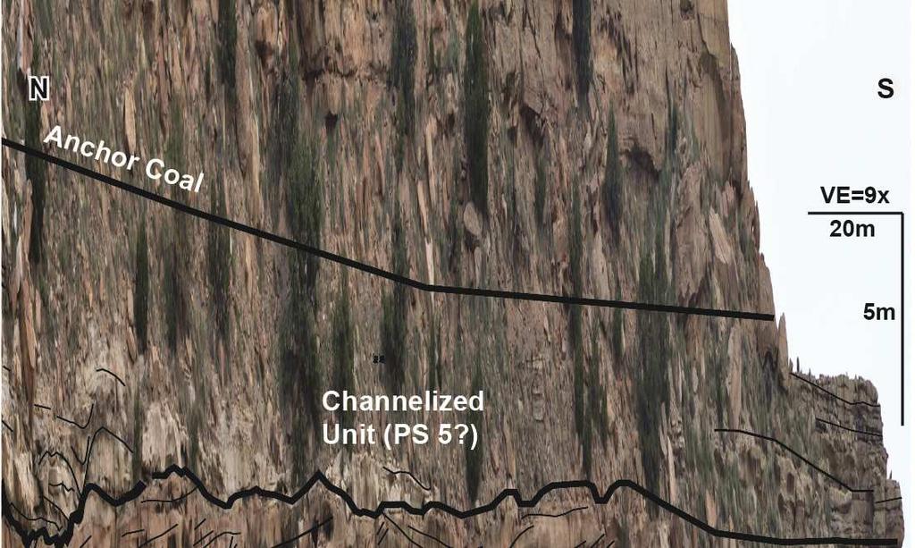
14 Cliffs, which are located along the southern periphery of the Piceance and Uinta Basins (Figure 2). Multiple regional stratigraphic studies have been conducted throughout the Book Cliffs, often with intricate and conflicting stratigraphic nomenclature (e.g., Young, 1955; Gill and Hail, 1975; Van Wagoner, 1991; Hettinger and Kirschbaum, 2002; Kirschbaum and Hettinger, 2004). This study employs the stratigraphic terminology from Kirschbaum and Hettinger (2004) which is slightly modified from Young (1955) (Figures 2, 4, and 5). The Upper Sego at Hunter Canyon consists of stacked deltaic and shoreface parasequences deposited by successive lowstand systems that prograded into the open marine conditions of the WIS (Figure 4; Franczyk, 1989; and Kirschbaum and Hettinger, 2004). This study examines one deltaic parasequence (PS), PS 3, which has previously been defined and interpreted as a river-dominated delta by Kirschbaum and Hettinger (2004). PS 3 downlaps the wave-dominated PS 2a (HC in Figure 4), which in Hunter Canyon was deposited in the lower shoreface. From Lipan Wash to Adobe Wash (LiW and AW in Figure 4, respectively), PS 3 is truncated and overlain by PS 4 and valley fill which is herein identified as the Channelized Unit (Figure 4). While a definitive relationship with marginal marine strata cannot be established, Kirschbaum and Hettinger (2004) interpret the Channelized Unit to be genetically related to PS Data and Methods The well-exposed Upper Sego Member crops out in three dimensions in the vicinity of Hunter Canyon, which is located about twenty-five kilometers north of Grand Junction, Colorado, in the eastern Book Cliffs (Figures 2 and 3). This study area extends from Hunter Canyon to two kilometers (straight line distance) to the west 3
15 (Figure 3). In this area of high outcrop rugosity, features of a river-dominated delta are well-exposed along multiple depositional perspectives Data and data integration Seventeen measured sections were collected at decimeter resolution (Figures 3 and 6, Appendix I). Measured sections document lithology, grain size, sedimentary structures, paleocurrent direction, biogenic structures, and the nature of stratigraphic surfaces. Most measured sections extend from the top of PS 2a to the top of the Anchor Coal, which served as bottom and top markers, respectively. The base and top of PS 3 were also identified throughout the study area. Measured sections were the basis for stratigraphic mapping along eighteen photopanels taken at centimeter-scale resolution. Photopanels were corrected for distortion. On two of these photopanels, Panels B and C (Figure 3), detailed lithologic character was mapped at the decimeter scale. Stratigraphic surfaces within the study interval were correlated along 11 kilometers of outcrop. Photopanels and measured sections were used to interpret styles of deposition within PS 3 (Figure 3). Lithology was quantified along one dip-oriented panel, Panel B. Panels A D were combined to create a fence diagram and an orthogonally-projected dip and strike diagram of the study area (Figure 3). The panels and fence diagram were used to interpret the paleogeographic evolution of PS 3 and evaluate architecture and distribution of facies. Results were compared with modern and ancient analogs of contrasting water depth, including the companion study in the Neslen Formation (O Brien, 2015). 4
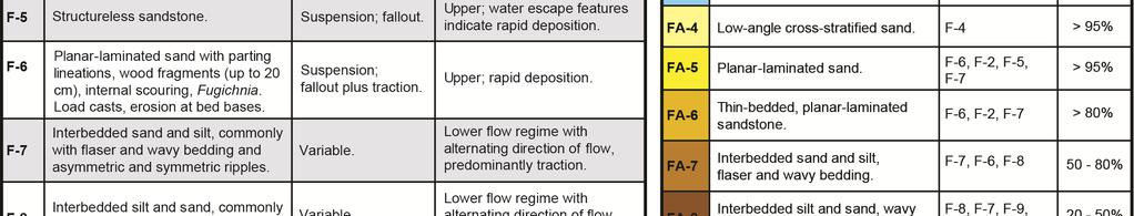
16 1.3.2 Facies and facies associations Sixteen facies were documented in the study area (Table 1). Each facies is distinctive in the context of grain size and sedimentary and/or biogenic structures. One or multiple facies were grouped into facies associations which were mappable on highresolution photopanels. Several facies associations differ primarily by percent sandstone (FA-6 and FA-7, FA-7 and FA-8). FA-10 and FA-15 are located only in PS 2a, 4, or 5. FA-14 is common in PS 2a and PS 4, but is rarely located in PS Components of river-dominated deltas Three deltaic components were identified in the study area. These are distributary channel, mouth bar, and prodelta (Figure 8). Distributary channels are the most updip part of the delta that is exposed in the study area. Distributary channels are lenticular in strike profile: their basal surfaces are concave-up and erosional into underlying strata. Distributary channels transfer downdip into mouth bars. This study uses the term mouth bar to refer to a continuous body of sediment deposited from a single distributary channel. This inclusive definition has the benefit of examining these continuous bodies of sediment as a single depositional body and reservoir flow unit. Three distinct regions of the mouth bar are identified in this study area: proximal, medial, and distal. The proximal mouth bar, the most updip region of a mouth bar, is located at sea level and is therefore visible in map-view images of modern deltas (Figure 8). The proximal mouth bar has been called flow expansion bar (Wright, 1977), inner mouth bar (Bhattacharya and Davies, 2004), middle-ground bar (Wright, 1977), friction-dominated mouth bar (Turner and Tester, 2006; Wright, 1977), and proximal 5
17 delta front terminal distributary channel (Olariu and Bhattacharya, 2006). The proximal mouth bar is convex-up and dominated by trough cross-stratified sandstone (FA-3, Table 1). The medial mouth bar is located immediately downdip of the proximal mouth bar. The medial mouth bar has been called outer mouth bar (Bhattacharya and Davies, 2004), upper delta front (Enge et al., 2010), inertial-detached mouth bar (Ahmed et al., 2014), and proximal delta front mouth bar (Olariu and Bhattacharya, 2006). The medial region of the mouth bar encompasses the shallowly sloping part of the clinoform that is immediately downdip of the proximal mouth bar to the base of the steeply dipping foreset (Figure 8). This region is sand-rich, dominated by planarlaminated sand and thin-bedded planar-laminated sand (FA-5 and FA-6, Table 1). The distal mouth bar, located immediately downdip of the proximal mouth bar, has been called outer mouth bar (Bhattacharya and Davies, 2004), frontal splay (Ahmed et al., 2014), lower delta front (Enge et al., 2010), and distal delta front distal mouth bar (Olariu and Bhattacharya, 2006). The distal mouth bar encompasses the region characterized by shallowly dipping, clinoforming surfaces (Figure 8). These clinoforming surfaces are the downdip continuation of the more steeply-dipping surfaces of the medial mouth bar. This region is heterolithic and more silt-rich (FA-7 and FA-8,Table 1) than the two updip regions. The prodelta is located immediately downdip of the distal mouth bar (Figure 8) and has been called frontal splay (Ahmed et al., 2014) and prodelta (Enge et al., 2010; Olariu and Bhattacharya, 2006). The prodelta interval is composed predominantly of structureless to laminated siltstone (FA-9, Table 1). 6
18 1.5 Hierarchy A four-tiered hierarchical classification was used to characterize the stratigraphy in the field area (Table 2). From smallest to largest, they are bed and bedset (Campbell, 1967), and story and element (Ford and Pyles, 2014) (Figure 9). Each hierarchical tier is characterized by its bounding surfaces, facies associations, and external shape in strike view (Pyles, 2007). Ford and Pyles (2014) define elements and stories for fluvial channels and their genetically-associated overbank deposits. For terminological continuity, this study extends the deepwater and fluvial hierarchical classifications from Pyles (2007) and Ford and Pyles (2014) to river-dominated deltas. Table 2 compares the hierarchical classes used in this study to other selected studies. A story is a meso-scale volume of strata formed from genetically-related beds or bedsets produced by the migration and fill of a channel (Ford and Pyles, 2014). The boundary between stories coincides with relatively minor shifts in the location of the depositional axis, paleocurrent direction, and facies resulting from migration (Straub and Pyles, 2012). An element is a macro-scale volume of strata formed from the migration of and flow expansion from a distributary channel (modified from Ford and Pyles, 2014). An element is composed of one or more stories (Pyles, 2007). The boundaries between stratigraphically adjacent elements reflect an abrupt and relatively large-scale shift in the location of the depositional axis, paleocurrent direction, and facies associated with avulsion (Straub and Pyles, 2012). This study uses three stratigraphic categories (distributary channel, mouth bar, and prodelta) to classify each hierarchical tier. Table 3 compares these stratigraphic categories with those of other studies of river-dominated deltas. These categories are 7
19 used as adjectives for the hierarchical tiers (sensu Straub and Pyles, 2012). Table 4 lists the facies associations observed in each category. Distributary channel and mouth bar stories collectively compose a channel-mouth-bar (CMB) element. CMB elements become thinner and finer-grained in the downdip direction as the transfer into the prodelta element (Figure 8). An example of the use of this hierarchical classification scheme is shown in Figure 9. 8
20 2 CHAPTER 2 RESULTS Chapter 2 discusses the results of this study, including the characteristics common to each type of element and story, and a description of each individual element. 2.1 Element types Two types of elements were identified in the study area. These are channelmouth-bar elements and prodelta elements (Table 2, Figure 9). This section provides a brief overview of the characteristics of channel-mouth-bar and prodelta elements. Channel-mouth-bar (CMB) elements are composed of distributary channels and their genetically related mouth bars. The strike morphology of a CMB element varies from lenticular (updip) to sub-tabular (downdip) (Figure 8). The basal stratigraphic surface is concave-up and highly erosional updip where the element is composed solely of a distributary channel (Figures 9, 10, and 13). The basal stratigraphic surface transitions to flat and conformable in the distal region of the mouth bar (Figure 12). The top stratigraphic surface transitions from flat (distributary channel, Figure 11) to strongly concave-up (proximal mouth bar, Figure 11) then asymptotically approaches flat (distal mouth bar, Figure 12). The thickest part of a CMB element, its axis, commonly contains a series of thickening-upward stories (Figure 9). The distal-most portion of CMB elements transfer into the prodelta element (north end of Panel B, Figures 12 and 13). The prodelta element is composed of prodelta stories and is exposed throughout the study area. Its thickness ranges from meters. This variability is primarily due to the uneven top of PS 2a, which the prodelta 9
21 element conformably overlies. The prodelta element has a width-to-thickness ratio in excess of 1000, reflecting its laterally extensive nature. 2.2 Story types Three types of stories were identified in the study area. These are distributary channel, mouth bar, and prodelta (Table 2, Figure 9) Distributary channel story Two distributary channel stories are exposed in strike profile with an average width and thickness of 130 and 3.6 meters (width-to-thickness ratio of 36; Figures 10 and 13, Table 5). Distributary channel stories are predominantly composed of trough cross-stratified sandstone or ripple-laminated sandstone (FA-3 or FA-2, Tables 26 and 4). Distributary channels predominantly composed of trough cross-stratified sandstone have bed bases that typically truncate into underlying beds. Silt rip-up clasts and contorted bedding are common. Distributary channel stories predominantly composed of ripple-laminated sandstone have weakly erosional bed bases and less rip-up clasts and contorted bedding compared to those that are composed of trough cross-stratified sandstone. The prevalence of FA-3 and FA-2 with silt rip-up clasts and truncation of underlying strata is interpreted to indicate alternating flow regimes. Contorted bedding is interpreted to result from rapid sedimentation and water escape, leading to slumping Mouth bar story Mouth bar stories compose the majority of the study interval (Figures 12 and 13) and vary downdip in their strike profile and constituent facies (Section 1.4). The proximal mouth bar is lenticular in strike profile. The basal stratigraphic surface is weakly erosional into underlying strata. The top stratigraphic surface is convex-up in 10
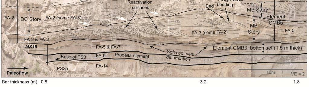
22 both strike and dip profiles. The proximal mouth bar is exposed in three mouth bar stories in the study area: two partial dip profiles (one shown in Figure 11) and one partial strike profile. The dominant facies association is trough cross-stratified sandstone (FA-3, Table 1). Most trough cross-strata within these stories are oriented in the same direction as the predominant paleocurrent, although a lesser proportion indicate sediment transport that is 180 to the predominant paleocurrent. The opposing trough cross-strata are mostly located on the stoss side of the mouth bar filling in scours. Reactivation surfaces are common; bioturbation is rare. Cross-stratified beds commonly build over the previous bar crest and continue over the crest to persist in the down-dip direction (Figure 11). Trough cross-stratified and ripple-laminated sandstone indicate the predominance of lower-flow regime conditions during deposition (Table 1). Sediment transport and deposition are interpreted to be dominated by bedload and traction, respectively. The most prominent features in the medial and distal regions of the mouth bar are clinoforming surfaces that define the top and base of each mouth bar story, and internal beds and bedsets within stories (Figures 12 and 13). The basal stratigraphic surface can be weakly erosive into underlying strata. The slope of clinoforming surfaces relative to the top of PS 2a decreases from a maximum of about 5 to near 0. Internal bedding surfaces are parallel to sub-parallel to the story bounding surfaces. These clinoforms are composed of topset, foreset, and bottomset regions, as defined by the position and angle along a clinoform. The radial rollover from topset to foreset is exposed in two orientations: dip and strike (Figure 8). While mouth bar stories contain dip-oriented rollovers, strike-oriented clinoforms dip only to the west (Figure 13). 11
23 Medial and distal mouth bar regions are composed of three types of strata. The first type of strata is composed of event beds dominated by planar-laminated, lower fine sand (FA-5 and FA-6). Ripple-laminated fine and very fine sand conformably overlie planar-laminated sand in some event beds, while wavy to laminated silt is also present at the top of a few event beds. This succession resembles T b, T c, and T d (sensu Bouma, 1962). Event beds thin and become more silt-rich down depositional dip. Wood fragments, organic matter, convolute laminae, and flame structures are common at the base of beds composed mostly of planar-laminated sandstone (FA-5, Table 1, Figure 7). Fugichnia is commonly present in bedsets thicker than 0.5m. Vertically-oriented Ophiomorpha is common in the medial and downdip parts of these same beds, while Skolithos is common in medial to updip parts. The second type of strata is composed of convoluted bedding. Intervals are lenticular in dip view. Erosion into underlying strata is common under the thickest part of an interval of convolute bedding (Figure 13, northern Panel C). These intervals abruptly pinch out downdip and are commonly overlain by the same type of strata that underlays them (Figure 13, Panel C). The third type of strata is composed of ripple-lamination, cross-stratification, and flaser, wavy, and lenticular bedding. Paleocurrents are typically bidirectional. These intervals thicken and become more heterolithic in medial and downdip portions of the mouth bar (Figure 12) and are dominated by flaser to lenticular bedding. Hummocky cross-stratification was observed only in a gutter cast in the distal portion of one mouth bar clinoform.. Swaley crossstratification was not observed. The first and second types of strata are interpreted to be deposited by turbidity currents and slumps, respectively. Evidence for the first includes the predominance of 12
24 planar-laminated sand; the upward and lateral transfer from planar-lamination to rippleand wavy-lamination to silt within event beds; and the progressive deamalgamation, thinning, and fining of beds downdip (Figures 12 and 13). These characteristics are consistent with deposition by turbidity currents (Bouma, 1962). Evidence for the second type of strata includes the characteristic lens shape, contorted bedding, and erosion into underlying strata (Figure 13). The third type of strata is interpreted to be the result of wave reworking and wave-influenced sedimentation. Wave energy is interpreted to be low because hummocky or swaley cross-strata were rarely observed in mouth bar stories. Bioturbated intervals of ripple-laminations and flaser to lenticular bedding are interpreted as evidence of periods of decreased or no river outflow. The intercalation of strata deposited by sediment gravity flow and wave influence indicates temporal variation in river discharge and wave energy Prodelta story Unlike CMB elements, the prodelta element cannot be subdivided into depositionally meaningful stories because no continuous stratigraphic surfaces could be identified as these strata are rich in mud and don t crop out as well as sandstones. However, single prodelta stories can be conceptualized as thin (<<0.1m), laterallyextensive sheets of structureless to laminated siltstone (Figure 9). Laminated silt is interpreted to have been deposited by waning flow of the deltaic turbidity currents responsible for deposition of the majority of the mouth bar stories. 2.3 Downdip and axis-to-margin changes within mouth bar stories The downdip transition from proximal to medial and distal regions of mouth bar stories reflects characteristic downdip changes in architecture, facies, and interpreted 13
25 depositional processes. From updip to downdip, mouth bar stories decrease in sand content. Mouth bar beds deamalgamate as they thin and become more silt-rich. Dominant bedforms transfer from trough cross-stratified sandstone to planar-laminated sandstone and finally flaser, wavy, and lenticular bedding with intervals of laminated silt (Figures 12 and 13). Interpreted depositional processes transition from bedload and traction (proximal mouth bar) to sediment gravity flow (medial and distal mouth bar). Coincident with these transitions, the bounding surfaces of mouth bar stories asymptotically decrease in slope from 5 to almost 0 (Figure 12). 2.4 Stratigraphy of Elements The following section outlines the element-scale characteristics of the study area. The characteristics of the delta compare favorably with other ancient river-dominated deltas (Table 6) Channel-mouth-bar element 1 Channel-mouth-bar element 1 (CMB 1) is exposed on Panels A and B (Figures 12 and 13; Figure 3 for location). The lower boundary of CMB 1 is conformable with the top of CMB 0 (not studied in detail) on Panel A (Figure 13, Appendix B-1). West from this location, the lower boundary of CMB 1 is conformable with, and laterally transfers into, the prodelta element (Figure 13). The maximum thickness of CMB 1, 8 meters, is on Panel A, halfway between measured sections 3 and 4 (Figure 13). The location of the axis of CMB 1 cannot be precisely determined because CMB 1 is truncated wherever it is not overlain by CMB 2 (Figure 13). Truncation has removed the proximal mouth bar and the topsets of the medial mouth bar, leaving only the medial and distal mouth bar regions (Figure 13, between measured sections 3 and 4). Thus, original 14
26 clinoform relief was greater than the truncated relief of 10 meters. CMB 1 is at least 900 meters wide with an exposed (partial) length of 800 meters. CMB 1 is composed of mouth bar stories that thicken and become more sand-rich from one to the next in an upward transect (Figures 9 and 12). The stories and bedsets composing CMB 1 laterally decrease in thickness and sand content from the location of greatest thickness (the axis) to the western margin. While the majority of CMB 1 is composed of fining-upward beds deposited by waning turbidity currents, wave-influenced intervals are also present. Facies and interpreted processes are described in more detail in Section 2.2. The mean paleocurrent direction is 041. Clinoforming stratigraphic surfaces are steepest on Panel A about 5 relative to the top of PS 2a where CMB 1 is first overlain by CMB 2, to the southwest. Exposures with steeply dipping clinoforms are locally oriented normal to the mean paleocurrent direction (Figure 13, dotted line on top of Panel A); thus, the steeply dipping clinoforms represent an axis-to-margin perspective. The distal mouth bar region of CMB 1 is exposed along Panel B (Figure 12). The average slope of the top of CMB 1 relative to the top of PS 2a is 0.15, which is an estimate of the minimum slope of the distal mouth bar relative to the top of PS 2a Channel-mouth-bar element 2 Element CMB 2 is the best-exposed element in the study area, where it crops out on Panels A, B, C and D (Figures 12 10). The lower boundary of CMB 2 is locally erosional into the underlying CMB 1 on Panel A from where it first overlies CMB 1 southwest to measured section 6 (Figure 13). CMB 2 is conformable along the remainder of Panel A and all of Panel B. CMB 2 is erosionally overlain by CMB 4 along the final 100 meters of the northern part of Panel B and erosionally overlain by CMB 3 15
27 on Panels C and D (Figures 12 and 13). Truncation (Figure 12) has removed the proximal mouth bar and most of the topsets of the medial mouth bar, leaving only the medial and distal mouth bar regions. Thus, original clinoform relief was greater than the current 11-meter relief. CMB 2 is about 1200 meters wide with a maximum exposed (partial) length of 540 meters the length of dip-oriented Panel B. Processes of deposition and upward and lateral trends in facies are the same as in CMB 1. The mean paleocurrent direction is 021. Maximum clinoform slopes are 5 relative to the top of PS 2a. Panel B represents a dip profile through an axial part of CMB 2 (Figure 12). The sand-rich medial mouth bar region of each story is located down-paleocurrent of the medial mouth bar region of the previous story (Figure 12). This dip-oriented stacking pattern indicates progradation of CMB 2 through time. Mouth bar stories become thinner as story boundaries become more gently dipping along the north end of Panel B. Gently-dipping parts of CMB 2 represent bottomset aggradation of approximately 4 meters at the north end of Panel B (Figure 12). Panel D-nw represents a strike profile through the northwest fringe of CMB 2; the northwest pinchout of CMB 2 is located approximately 150 meters to the north of Panel D-nw. CMB 2 thins as stratigraphic surfaces dip gently to the west along Panel D-nw (Figure 10). A distributary channel story is exposed on Panel C (Figure 13). The lower boundary is concave-up and erosional into the mouth bar stories of CMB 2. The exposure is roughly laterally symmetrical. Soft sediment deformation in the underlying CMB 2 is present directly below the middle of the distributary channel (Figure 13). The width and maximum thickness of the distributary channel story are 3.7 and 120 meters, respectively. This corresponds to a width-to-thickness ratio of 32. The distributary 16
28 channel story is largely inaccessible, and no reliable paleocurrents could be collected. The approximate lateral symmetry of CMB 2 on Panel C (Figure 13, Appendix B-3) suggests that the channel is oriented into Panel C (ca. 320 ) Channel-mouth-bar element 3 CMB 3 is composed of a distributary channel story and mouth bar stories. Both types of stories are described before examining their interrelationship. Mouth bar stories crop out on Panels C, D, and E (Figures 13, 10, and, respectively; Figure 3 for locations). The nature of the lower boundary changes dramatically along its exposure. At the north end of Panel C (Figure 13), the lower boundary of CMB 3 truncates stratigraphic surfaces of the underlying CMB 2. The lower boundary of CMB 3 becomes conformable halfway to the southern end of Panel C (Figure 13). The maximum thickness of CMB 3 is 7 meters (on Panel C, Figure 13), while the total clinoform relief is 15 meters. The topsets of the medial mouth bars are well preserved over a portion of Panel C (Figure 13). CMB 3 is 850 meters wide with an exposed length of 700 meters. The western margin of CMB 3 is located immediately west of Panel E; Figure 11 shows the 1.5-meter-thick distal mouth bar (bottomset) of CMB 3. Processes of deposition and upward and lateral trends are the same as in CMB 1 and CMB 2, with one addition: slumps (Section 2.2.2; FA-13, Table 1) in CMB 3 are exposed in overlying the location of maximum apparent erosion into CMB 2 (shown in purple in Figure 13). The mean paleocurrent direction is 025. Clinoform angles and upward vertical trends of stories and bedsets are similar to those of CMB 1 and CMB 2. A distributary channel story within CMB 3 is exposed on Panel D-nw (Figures 9, 13, and 10). The lower boundary of this distributary channel story is erosional into older 17
29 mouth bar stories of CMB 3 (Figure 9). The east channel margin is exposed on Panel D- nw (Figures 13 and 10). While the west margin has been removed by modern erosion, the base of the channel is sloping upward (Figures 13 and 10), suggesting that the western margin of the distributary channel was close to the western edge of Panel D- nw. The width and thickness of the channel are 140 and 3.5 meters, respectively, with a width-to-thickness ratio of 40. This distributary channel has the characteristics of distributary channel stories dominated by trough cross-stratified sand (FA-3, Table 1; Section 2.2.1). The concave-up, erosionally-based distributary channel story transfers downdip to amalgamated, clinoforming bedsets of planar-laminated sandstone (FA-5, Table 1; MS15, meters 5-8, Appendix 1) with the vertical and horizontal trends observed in the medial region of a mouth bar story. This facies transition is interpreted to be the downdip transfer from a distributary channel story to a mouth bar story. This transition occurs over the 130 meters between Figure 10 (lenticular distributary channel) and Figure Channel-mouth-bar element 4 Channel-mouth-bar element 4 is exposed on Panel B (Figures 12 and 13), where it is entirely composed of mouth bar stories. The lower boundary is erosional into CMB 2 in locations dominated by planar-laminated and cross-stratified sand, while becoming conformable to the north. The top bedset of CMB is intensely bioturbated, predominantly by Ophiomorpha. CMB 4 is overlain by intensely bioturbated sand and flaser, wavy, and lenticular bedding of PS 4 (Figure 12). CMB 4 has a maximum exposed thickness and length of 2 and 90 meters, respectively. The clinoform topset of 18
30 CMB 4 is preserved (Figures 12 and 13, Appendix I), indicating that CMB 4 is wellpreserved. The top of CMB 4 is a maximum of 10.2 meters above the top of PS 2a (See Appendix 1). Lateral facies trends are the same as those described in the medial and distal regions of mouth bar stories (Section 2.2.2). One paleocurrent was measured (cross-stratification) with a sediment transport direction of Channel-mouth-bar element 5 Channel-mouth-bar element 5 (CMB 5) is exposed on Panel E (Figure 11) in the western part of the study area (Figure 3). From MS 16 to the northeast, CMB 5 overlies the western distal mouth bar region of CMB 3. While the lower boundary of CMB 5 is largely conformable, erosion is present underneath the story highlighted by white arrows in Panel E (Figure 11). The thickness of CMB 5 is about 6 meters at MS 16 (Appendix 1). The mean paleocurrent direction is 347. Two types of stories were observed in CMB 5: mouth bar stories (proximal region, Section 2.2.2) and distributary channel stories (Section 2.2.1) dominated by ripple-laminated sandstone (FA-2, Table 1). The mouth bar story highlighted by white arrows in Figure 11 is a relatively complete dip-oriented exposure of its proximal mouth bar region. The upper stratigraphic surface can be traced over the convex-up bar-form (white arrows in Figure 11) and demarcates a change from predominantly trough crossstratified sandstone to predominantly ripple-laminated sandstone (median grain size, lower fine sand). This boundary is interpreted as the boundary between the proximal region of a mouth bar story and a distributary channel: a juxtaposed distributary channel must be located updip of the proximal mouth bar as a sediment source. Superposition of the ripple-laminated sandstone indicates that it was deposited after the mouth bar. 19
31 The trough cross-strata of the mouth bar indicate greater depositional energy than in the ripple-laminated distributary channel. Distributary channels typically show higher depositional energy than mouth bars: flow in distributary channels is laterally confined whereas flow on mouth bars is decelerating due to vertical and horizontal flow expansion into the basin (Edmonds and Slingerland, 2007; Wright, 1977). However, superposition of the distributary channel indicates that the distributary channel was deposited after the mouth bar. One potential explanation for this apparent reversal in depositional energy is that the distributary channel was abandoned and subsequently filled with lower-energy ripple-laminated sandstone. 20
32 3 CHAPTER 3 PALEOGEOGRAPHY AND WATER DEPTH The paleogeographic evolution of PS 3, shown in Figure 15, was reconstructed using superposition and cross-cutting relationships of stratigraphic surfaces, as documented in photopanels A E (Figures 11, 12, and 13; Appendices A and B). The paleogeographic map was constructed using the assumption that the total length of CMB elements are twice their measured width, based on the average length-to-width ratios documented by Reynolds (1999) and Wellner et al. (2005). Successive CMB elements in the study area sidelap each other, resulting in the westward stacking of the system through time (Figure 16). This unidirectional lateral stacking pattern between elements contrasts with observations from the modern Wax Lake Delta, in which elements stack predominantly basinward. Wellner et al. (2006) document that the processes of bifurcation and channel abandonment result in an architecture in which patterns at the bedset scale are also seen in the story, element, and complex scale (i.e., fractal architecture). The architecture of PS 3, in contrast, is hierarchical or scale-dependent because stories stack predominantly basinward whereas elements stack predominantly laterally (Sections and 2.4, Figures 13 and 15). Understanding the evolution of water depth during the deposition of a study interval provides important context in interpreting its paleogeographic setting and the interval s context within rising, falling, or static sea level. Two assumptions were made when estimating the water depth of the CMB elements. 1. The height of the convex-up proximal mouth bar can be used to estimate water depth into which it was deposited. 21
33 The results of the numerical model of Edmonds and Slingerland (2007) indicate that bifurcation of a distributary channel is initiated when a proximal mouth bar aggrades to 60% of the water depth. Bifurcation results in bypass of the effluent of the proximal mouth bar. Abandonment of one arm commonly occurs, whereby the formerly-active proximal mouth bar is amalgamated with neighboring proximal mouth bars by lowerenergy sedimentation (i.e., Figures of Wellner et al., 2005). Panel E (Figure 11) exhibits a bar-form composed predominantly of trough cross-stratified sandstone, which is surrounded by lower-energy ripple-laminated sandstone. The stratigraphic surface separating the two (indicated by white arrows in Figure 11) is interpreted to be the record of bifurcation about a subaqueous proximal mouth bar and subsequent abandonment of the distributary channel. Further aggradation within CMB 5 continued under lower-energy conditions. This is not to suggest that PS 3 was entirely subaqueous: further aggradation between and atop laterally amalgamated mouth bar stories could have led to subaerial exposure. The total relief of CMB 5 is interpreted to be greater than the depositional water depth (shown as the dashed grey line in Figure 11). 2. Where only medial and distal mouth bars are exposed, water depth is estimated by the total height of the clinoforms. The total height of truncated clinoforms (CMB 1 and CMB 2, Figures 12 and 13) was estimated by calculating the average radius of curvature of the transition from foreset to topset of fully-preserved clinoforms (CMB 3). This radius of curvature was used to calculate the height at which the truncated clinoform would have achieved zero degrees relative to PS 2a. This method estimates the minimum depositional water depth. The medial to distal regions of a mouth bar can be deposited significantly below sea level (Ahmed and Bhattacharya, 2014). Further, 22
34 this estimate does not account for the additional water depth that the updip proximal mouth bar region requires (see above). The key conclusion is that the field area exposes different mouth-bar regions that were deposited in contrasting water depths. The proximal mouth bar region was deposited in approximately 5.5 meters of water, while the medial to distal mouth bar regions were deposited in deeper water. The minimum water depths of CMB elements 1, 2, and 3 (medial to distal regions), estimated using the second assumption (above), are 13.5, 12, and 15 meters. While the water depth of CMB 4 cannot be accurately determined, the bottomset aggradation of CMB 2 (dotted grey line in Figure 12; Section 2.4.4) has decreased the water depth of CMB 4. The water depth of CMB 5 (proximal region) is estimated at 5.5 meters using the first assumption (above). The variability in interpreted water depth between CMB 1 CMB 3 and CMB 5 (15 vs. 5.5 meters) could be created by westward-shallowing topography of PS 2a. The eastern Book Cliffs are generally viewed as a dip-oriented exposure of the Mesaverde Group (Zapp and Cobban, 1960). Evidence of westward shallowing in the study area is consistent with these interpretations. The 1.5 meters of bottomset aggradation from CMB 3 (Figure 11) is not a significant contributor to this discrepancy. Alternatively, falling sea level cannot be ruled out: CMB 5 is composed entirely of the proximal mouth bar region in Panel E (Figure 11), where it downlaps the distal mouth bar region of CMB 3. This apparent basinward dislocation in facies could be interpreted as evidence of falling sea level. Additional study is necessary to further constrain the interpretation. 23
35 4 CHAPTER 4 COMPARISON OF DELTAS DEPOSITED IN CONTRASTING WATER DEPTHS The purpose of this section is to test the implications of Edmonds et al. (2011) model based on the results from two outcrop studies in the Neslen and Iles Formations, conducted by Kimber O Brien and Matthew Andresen, respectively (Figures 2, 4, and 16). A stratigraphic comparison between the Neslen delta and the Iles delta validates the prediction of Edmonds et al. (2011) model that mouth bars have different architectures based on water depth. This comparison suggests modifications that can increase the accuracy and of the model. The result of this stratigraphic comparison validates the prediction that water depth influences deltaic architecture (Wright 1977; Edmonds et al., 2011). This comparison supports the assertion of Wright (1977) that bed friction is relatively more significant in shallow-water and reduces the turbulence of the outflow. Enhanced bed friction in shallow water results in tractive depositional conditions, whereas reduced bed friction in deeper water results in a higher proportion deposition from suspension. The following discussion compares and contrasts the two deltas. The Neslen and Iles deltas are ideally-suited for this paired study. The deltas were deposited in contrasting water depths of 4 m and 15 m, respectively (Table 7). Within each partial delta complex, both deltas are river-dominated and exhibit minimal influence or modification by waves or tides due to a relatively high proportion of lithofacies deposited by tractive currents. Deposited in the Campanian, the deltas are roughly coevally deposited shallow-marine systems that represent strata deposited along a depositional profile from the coastal plain to open marine (Figure 2). Thus, the 24
36 results are indicative of the variability within a depositional landscape. Finally, the deltas are exposed spectacularly in three dimensions so that the distinctive architectures can be studied from multiple depositional perspectives. Both studies use the same types of data and the same methodology to document the stratigraphic architecture and spatiotemporal evolution of partial delta lobes. Data include: 1) stratigraphic columns, 2) high-resolution photopanels, 3) sediment transport directions, and 4) locations of deltaic features on a topographic map (Figure 3). Both studies use a five-tier hierarchy modified from existing fluvial and deep-water hierarchies. From smallest to largest, the hierarchical components are: bed, bedset, story, element, and complex (Figure 8, Table 2). The dominant lithofacies in the Neslen delta is composed of 57 percent rippled sandstone, whereas the Iles delta is composed of 49 percent planar-laminated sandstone exhibiting partial Bouma sequences (Figure 16). The Neslen delta also contains planar-laminated sandstone (11 percent); however, it is interpreted to be deposited by traction because the bedsets have erosional boundaries without any gradational transition to ripple-laminated sandstone as opposed to the planar-laminated sandstone in the Iles delta. The difference in dominant lithofacies is the result of different flow processes building mouth-bars in each delta. The dominant flow processes for the Neslen and Iles deltas are interpreted to be lower to upper flow regime traction plus suspension deposition. However, there is no evidence of deposition purely by suspension in the Neslen delta. Preserved graded beds and Bouma sequences in the Iles delta indicate that there is preserved deposition from suspension and the system was more prone to the formation of turbidites. 25
37 The lateral and longitudinal variations of lithofacies result in distinct architectural styles in each delta. On average, the constituent beds within the Neslen delta are more vertically amalgamated than the Iles delta (Figure 17) and more amalgamated throughout the body of the delta (Figure 16). The Neslen delta has a higher proportion of sand-rich lithofacies along its fractional length with comparatively fewer shale breaks than the Iles delta (as demonstrated by the table in (Figure 18). There is little bottomset aggradation in the Neslen delta whereas the Iles delta has laterally persistent and aggradational bottomset (prodelta) strata (Figure 17). The average element width is 540 m and 1000 m for the Neslen and Iles deltas, respectively. The element aspect ratios (width/thickness) are greater in the Neslen delta than the Iles delta, 140 and 110, respectively. The overlap of stratigraphically-adjacent bodies averages 55% and ~90% for stories in the Neslen and Iles deltas, respectively, and 15% and 57% for elements (Figure 18), indicating that the Neslen delta stacks more compensationally. More overlap of mouth bars in the Iles delta indicates the mouth bars stack more vertically than their shallow-water counterparts. The Neslen delta stacks more compensationally because of the limited accommodation space created by the shallow-water depth and the low gradient. The higher gradient in the Iles delta results in higher accommodation space and thus a higher propensity for mouth bars to stack vertically. The higher gradient in the Iles delta is also the likely cause for the presence of turbidites because a higher gradient indicates a higher probability of slope failure. According to this comparison, shallow-water deltas are dominated by tractive deposition, have minimal bottomset aggradation, and stack highly compensationally (Table 7). The deltas also share several important similarities. The stratigraphic 26
38 architecture in the proximal portions of the deltas is similar because they are deposited in similar water depths near the apex of the river. For example, proximal portions of the deltas have similar proportions of topset strata and similar compensational stacking patterns. These similarities are attributed to the similar water depth of the deltas in the up-current part of the systems (Figure 1). It is hypothesized that if the Neslen delta continued to prograde into deeper-water it would eventually become stratigraphically similar to the Iles delta. 27
39 5 CHAPTER 5 CONCLUSIONS 1. Parasequence 3 of the Upper Sego was deposited by a river-dominated delta. Distributary channel, mouth bar, and prodelta stories and channel-mouth-bar and prodelta elements were identified in the study area. Channel-mouth-bar elements were deposited in at least 15 meters of water. Wave influence in PS 3 was minor. 2. Mouth bar stories have three stratigraphically-distinct regions: proximal, medial, and distal. The proximal mouth bar region is convex-up and lenticular in shape and is composed of amalgamated, trough cross-stratified sandstone. Deposition occurred via bedload under tractive conditions. The medial and distal mouth bar regions are composed of clinoforming surfaces that define the top and base of intervals that become increasingly silt-rich downdip. The medial mouth bar is dominated by amalgamated, planar-laminated sandstone, while the distal mouth bar is dominated by thinner-bedded, heterolithic strata. Event beds are commonly composed of partial Bouma sequences. Deposition was primarily by turbidity currents with some slumping. Wave energy periodically reworked mouth bars. Mouth bar stories are characterized by significant bottomset aggradation which reduced the slope and water depth for subsequent stories. 3. The stacking pattern of mouth bars differs according to hierarchical tier. Mouth bar stories stack parallel to the predominant intra-element paleocurrent. In contrast, mouth bar elements stack perpendicular to the mean overall paleocurrent, 021. In strike view, each mouth bar element side-laps the next 28
40 older mouth bar element located to its east. Axis-to-margin clinoforms dip only to the west. The stratigraphic architecture of PS 3 varies by scale, and is thus hierarchical, not fractal. 4. The results of this study and O Brien (2015) support the hypothesis that deeperwater and shallower-water mouth bars exhibit characteristic differences in their stratigraphic architecture and facies distribution. Deeper-water mouth bars are more likely to be deposited by sediment gravity flow, with a high proportion of turbidite and/or mass failure deposits. In contrast, shallower-water mouth bars are more likely to be deposited by bedload, resulting in tractive facies such as ripples and trough cross-strata. Deeper-water mouth bar elements are likely to be larger, exhibit far greater bottomset aggradation, and stack less compensationally than shallower-water mouth bar elements. 5. This study documents significant bottomset aggradation in PS 3. Bottomset aggradation locally shallows the depth and slope of the surface onto which subsequent mouth bars are deposited. As such, this study suggests that bottomset aggradation be accounted for in future numerical stratigraphic models of river-dominated deltas. 29

 differ from their deeper water (bottom)")
41 FIGURES Figure 1. A. Map view photography of two deltas showing similarity in their plan-view characteristics: left, Okavango Delta, deposited in ca. 3 meters of water depth; right, Mississippi Delta, deposited in 25+ meters of water depth. B. Schematic longitudinal cross-sections illustrating how deltas deposited in shallower water (top) differ from their deeper water (bottom) counterparts (concept from Edmonds et al., 2011). Shallower water deltas have a higher proportion of topset-dominated strata along a dip profile than their deeper-water counterparts. 30


42 Figure 2. Stratigraphic cross section of the Book Cliffs, Utah and Colorado. The study area is located in the Iles Formation, whereas a companion project is located in timeequivalent strata deposited in a coastal plain environment, in the Neslen Formation. Both are formations within the larger Mesaverde Group. Green River (GR) and Grand Junction (GJ) are shown on the index map for reference. Cross-section from Hettinger and Kirschbaum (2002). 31

43 Figure 3. Topographic map showing the spatial location of PS 3 (black line) and data collected in this study. The rugosity of the outcrop exposes PS 3 along multiple perspectives. See Figure 2 for the regional location of the study area. 32


44 Figure 4. Stratigraphic cross section of the Iles Formation in the Grand Junction area (Kirschbaum and Hettinger, 2004). Stratigraphic architecture and interpreted depositional environment are based on outcrop and subsurface data. This study is focused on Parasequence 3, which was deposited by a river-dominated delta during a sea-level lowstand. See Figure 2 for larger context. 33


45 Figure 5. Stratigraphic chart of Upper Cretaceous strata in the Uinta and Piceance Basins, including Campanian ammonite zones of the Western Interior. This study focuses on one parasequence within the Upper Sego member of the Iles Formation in Colorado. Stratigraphic nomenclature is modified from Young (1955), Hettinger and Kirschbaum (2002), and Kirschbaum and Hettinger (2004). Stratigraphic chart modified from Franczyk (1989). 34
46 Figure 6. Measured section (MS 3) depicting a vertical profile through PS 3, PS 4, and the Channelized Unit. The location of MS 3 is depicted in Figure 3. See Table 1 for a description of facies associations, and Appendix A for additional examples of measured sections. 35


47 36


48 Figure 7. Pictures of facies associations that are most common in Parasequence 3. See Table 1 for a list and description of all facies associations. 37
49 Figure 8. Schematic diagram of a portion of a delta, showing a tear-drop-shaped mouth bar elongated in the down-paleocurrent orientation. Four strike-oriented cross sections (A-D and one dip-oriented cross section (E) show the idealized architecture and distribution of facies associations (see Table 1). Within the mouth bars, two clinoform rollovers are defined: strike-oriented (highest point in C) and dip-oriented (approximate midpoint of FA-5 and FA-6, in E). The dip-oriented rollover is the boundary between the lower-angle topset and higher-angle foreset. An idealized location and scale of the diagram is shown by the black box in the aerial photograph to the upper-left. 38


50 39


51 Figure 9. Stacking patterns according to hierarchical tier. Orange arrows indicate coarser grain size upward, whereas blue arrows indicate finer grain size upward. Ovals indicate very thin bedsets and stories with stacking patterns that are too small to graphically represent. (A) encompasses the top of PS 2a and most of PS 3, and is the site of measured section 3 (Figures 3 and 6). (B) is located on Panel D-nw (Figure 3). 40
52 Figure 10. Photopanels D-s and D-nw projected according to outcrop orientation. Panels are oriented along depositional dip and strike, respectively. Element CMB 3 overlies CMB 2; both are primarily composed of mouth bar stories. A distributary channel story within CMB 3 incises into older mouth bar stories also within CMB 3. Vertical exaggeration is 9x and viewing direction is 060. Legend included in Figure 12. See Figure 3 for location. 41
53 Figure 11. (a) Uninterpreted and (b) interpreted photograph of Panel E (Figure 3). Within element CMB 5, three stories are exposed: one distributary channel story and the proximal part of two mouth bar stories. White arrows indicate the top of one mouth bar story. A distributary channel story overlies the stratigraphic surface indicated by white arrows (Section 2.4.5). A second mouth bar story overlies the first. Reactivation surfaces are common along bed boundaries. Estimated depositional water depth, 5.5 meters, is shown as a dotted line in (b) toward the top of PS 3. Paleoflow is from left to right. Vertical exaggeration (VE) is 2x. 42


54 43
55 Figure 12. Cross-section of Panel B, which is a longitudinal profile through elements P, CMB1, CMB2, and CMB4 of PS 3. The outcrop is oriented precisely north-south, while the mean sediment transport direction, 025, is from right to left and obliquely into the page. Facies percentages for each element and all of PS 3 exposed on Panel B are listed in the table beneath the cross-section. See Figure 3 for location. 44
56 Figure 13. Fence diagram illustrating the 3-D stratigraphic architecture of PS 3. The diagram is oriented normal to the sediment transport direction, which is 025. Note that only FA-5 (planar-laminated sandstone, Table 1), which was deposited by upper flow regime sediment gravity flows, has been mapped on Panels A and D. Undistorted panels are shown in Appendix II. See Figure 12 for legend.. 45


57 Figure 14. Photopanel D-b annotated with stratigraphic surfaces. Within PS 3, two elements, CMB 2 and CMB 3, are exposed. The white arrow highlights the location of the downdip transition from a distributary channel story to a mouth bar story within CMB 3. Panel D-b is located immediately north of Panel D-nw (Figures 13 and 10; see Figure 3 for location). Vertical and lateral parallax has not been corrected. Legend for stratigraphic surfaces is included in Figure
58 Figure 15. A. Map showing the paleogeographic evolution of PS 3 in the Hunter Canyon area. B. Rotated image of Wax Lake Delta showing one paleogeographic model for the deposition of PS 3. 47

59 Figure 16. Dip-oriented cross-sections through the Neslen delta (top) and Iles delta (middle). Detailed facies are mapped on the cross-sections. For the location of the study areas, see Figures 2 and 3. 48

 and the Iles delta (this study).")

60 Figure 17. A comparison of vertical transects through the Neslen delta (O Brien, 2015) and the Iles delta (this study). Mouth bar beds in the Neslen delta are more vertically amalgamated than mouth bar beds in the Iles delta. 49
 and the Iles delta (right).")
61 Figure 18. Diagram comparing the story-scale characteristics for the Neslen delta (left) and the Iles delta (right). The mouth-bar stories in the Iles delta are more heterolithic and larger than mouth bars in the Neslen delta. 50
62 TABLES Table 1 (next page). (a) Facies and (b) facies associations identified in the study area. Facies that compose facies associations are listed in the second column from the right in (b). The colors included in the first column of (b) are the same as those depicted in the interpreted photopanels (Figures 12 and 13). 51


63 52
64 Table 2. Table comparing the hierarchical tiers used in this study with those used in studies of other depositional environments. Table 3. Table comparing the components mapped in a hierarchical construct in this study to that of selected other studies. 53
65 Table 4. Facies associations comprising each parasequence (outside of PS 3) and type of story (within PS 3). See Table 1 for descriptions of facies associations. 54

66 Table 5. Table with dimensions of elements and the amount of overlap between them. 55


67 Table 6. A comparison of the delta worked in this study, selected ancient deltas that were also deposited in the Western Interior Seaway, and the well-studied Lagniappe Delta from subsurface Gulf of Mexico. 56
68 Table 7. Comparison among Iles Formation elements CMB 1 CMB 3, Iles Formation element CMB 5, and Neslen Formation elements (O Brien, 2015). 57
69 REFERENCES Ahmed, S., J. P. Bhattacharya, D. E. Garza, and Y. Li, 2014, Facies architecture and stratigraphic evolution of a river-dominated delta front, Turonian Ferron Sandstone, Utah, USA: Journal of Sedimentary Research, v. 84, p Anderson, P. B., T. C. Chidsey Jr, T. A. Ryer, R. D. Adams, and K. McClure, 2004, Geologic framework, facies, paleogeography, and reservoir analogs of the Ferron Sandstone in the Ivie Creek area, east-central Utah in T. Chidsey, R. Adams, and T. Morris, eds., The fluvial-deltaic Ferron Sandstone: Regional-to-wellborescale outcrop analog studies and applications to reservoir modeling, AAPG Studies in Geology 50, p Aschoff, J., and R. Steel, 2011, Anomalous clastic wedge development during the Sevier-Laramide transition, North American Cordilleran foreland basin, USA: Geological Society of America Bulletin, v. 123, p Bhattacharya, J. P., 2008, Applying the clinoform concept to correlation of deltaic and shallow marine deposits: 2008 Joint Meeting of The Geological Society of America, Soil Science Society of America, American Society of Agronomy, Crop Science Society of America, Gulf Coast Association of Geological Societies with the Gulf Coast Section of SEPM Bhattacharya, J. P., and R. K. Davies, 2004, Sedimentology and structure of growth faults at the base of the Ferron Sandstone Member along Muddy Creek, Utah, in T. Chidsey, R. Adams, and T. Morris, eds., The fluvial-deltaic Ferron Sandstone: Regional-to-wellbore-scale outcrop analog studies and applications to reservoir modeling, AAPG Studies in Geology 50, p Bouma, A. H., 1962, Sedimentology of some flysch deposits: a graphic approach to facies interpretation: Elsevier Amsterdam, 168 p. Campbell, C. V., 1967, Lamina, laminaset, bed and bedset: Sedimentology, v. 8, p DeCelles, P. G., 2004, Late Jurassic to Eocene evolution of the Cordilleran thrust belt and foreland basin system, western USA: American Journal of Science, v. 304, p Edmonds, D., and R. Slingerland, 2007, Mechanics of river mouth bar formation: Implications for the morphodynamics of delta distributary networks: Journal of Geophysical Research, v. 112, F Enge, H. D., J. A. Howell, and S. J. Buckley, 2010, Quantifying clinothem geometry in a forced regressive river dominated delta, Panther Tongue Member, Utah, USA: Sedimentology, v. 57, p
70 Ford, G. L., and D. R. Pyles, 2014, A hierarchical approach for evaluating fluvial systems: Architectural analysis and sequential evolution of the high net-sand content, middle Wasatch Formation, Uinta Basin, Utah: AAPG Bulletin, v. 98, p Franczyk, K. J., 1989, Depositional controls on the late Campanian Sego Sandstone and implications for associated coal-forming environments in the Uinta and Piceance basins: U.S. Geological Survey Bulletin 1787-F, 17 p. Gill, J. R., and W. J. Hail, 1975, Stratigraphic sections across Upper Cretaceous Mancos Shale-Mesaverde Group boundary, eastern Utah and western Colorado: USGS Oil and Gas Investigation Chart OC-68. Hettinger, R. D., and M. A. Kirschbaum, 2002, Stratigraphy of the Upper Cretaceous Mancos Shale (upper part) and Mesaverde Group in the southern part of the Uinta and Piceance basins, Utah and Colorado: U.S. Geological Survey Investigations Series I-2764, 21 p. Kirschbaum, M. A., and R. D. Hettinger, 2004, Facies analysis and sequence stratigraphic framework of Upper Campanian strata (Neslen and Mount Garfield Formations, Bluecastle Tongue of the Castlegate Sandstone, and Mancos Shale), eastern Book Cliffs, Colorado and Utah: U.S. Geological Survey Digital Data Series DDS-69-G, 40 p. Moss-Russell, A. C., 2009, The stratigraphic architecture of a prograding shelf-margin delta in outcrop, the Sobrarbe Formation, Ainsa Basin, Spain, Masters Thesis, Colorado School of Mines, 192 p. O'Brien, K., 2015, Stratigraphic architecture of a shallow water delta in a coastal plain setting, Masters Thesis, Colorado School of Mines, 66 p. Olariu, C., and J. P. Bhattacharya, 2006, Terminal distributary channels and delta front architecture of river-dominated delta systems: Journal of Sedimentary Research, v. 76, p Olariu, C., R. J. Steel, and A. L. Petter, 2010, Delta-front hyperpycnal bed geometry and implications for reservoir modeling: Cretaceous Panther Tongue delta, Book Cliffs, Utah: AAPG bulletin, v. 94, p Pyles, D. R., 2007, Architectural elements in a ponded submarine fan, Carboniferous Ross Sandstone, western Ireland: Atlas of deep-water outcrops: AAPG Studies in Geology, v. 56, p Reynolds, A. D., 1999, Dimensions of paralic sandstone bodies: AAPG bulletin, v. 83, p Roberts, H. H., R. H. Fillon, B. Kohl, J. M. Robalin, and J. C. Sydow, 2004, Depositional architecture of the Lagniappe Delta: sediment characteristics, timing of 59
71 depositional events, and temporal relationship with adjacent shelf-edge deltas, in J. B. Anderson, and R. H. Fillon, eds., Late quaternary stratigraphic evolution of the northern Gulf of Mexico margin, SEPM Special Publication 79, p Roberts, L. N. R., and M. A. Kirschbaum, 1995, Paleogeography of the Late Cretaceous of the Western Interior of middle North America-coal distribution and sediment accumulation: United States Geological Survey, Professional Paper 1561, 115 p. Straub, K. M., and D. R. Pyles, 2012, Quantifying the hierarchical organization of compensation in submarine fans using surface statistics: Journal of Sedimentary Research, v. 82, p Turner, B. R., and G. N. Tester, 2006, The Table Rocks Sandstone: A fluvial, frictiondominated lobate mouth bar sandbody in the Westphalian B Coal Measures, NE England: Sedimentary Geology, v. 190, p Van Wagoner, J. C., 1991, High-frequency sequence stratigraphy and facies architecture of the Sego Sandstone in the Book Cliffs of western Colorado and eastern Utah, in J. C. Van Wagoner, D. Nummedal, C. R. Jones, D. R. Taylor, D. C. Jennette, and G. W. Riley, eds., Sequence stratigraphy applications to shelf sandstone reservoirs; outcrop to subsurface examples: AAPG Field Conference Guidebook, p Wellner, R., R. Beaubouef, J. Van Wagoner, H. Roberts, and T. Sun, 2005, Jet-plume depositional bodies The primary building blocks of Wax Lake Delta: Transactions of the Gulf Coast Association of Geological Societies, v. 55, p Wright, L., 1977, Sediment transport and deposition at river mouths: a synthesis: Geological Society of America Bulletin, v. 88, p Young, R. G., 1955, Sedimentary facies and intertonguing in the Upper Cretaceous of the Book Cliffs, Utah-Colorado: Geological Society of America Bulletin, v. 66, p Zapp, A. D., and W. A. Cobban, 1960, Some Late Cretaceous strand lines in northwestern Colorado and northeastern Utah: U.S. Geological Survey, Professional Paper 400-B, p. B246-B
72 APPENDIX A MEASURED SECTIONS 61
73 Figure A-1. Cross-section and measured sections on Panel A and to the north. 62
74 Figure A-2. Cross-section and measured sections of Panel B. 63
75 Figure A-3. Cross-section and measured sections west of Panel B. 64


76 APPENDIX B INTERPRETED PHOTOPANELS IN ORTHOGONAL VIEW Figure B-1. Panel A, uncorrected for parallax. 65


77 Figure B-2. Panel B, uncorrected for parallax. 66


78 MS 15 Figure B-3. Panel C, uncorrected for parallax. 67

")
,")

79 Figure B-4. Panels D-nw (A) and D-s (B), uncorrected for parallax. 68
STRATIGRAPHIC ARCHITECTURE OF A SHALOW-WATER DELTA DEPOSITED IN A COASTAL-PLAIN SETTING: NESLEN FORMATION, FLOY CANYON, UTAH
 STRATIGRAPHIC ARCHITECTURE OF A SHALOW-WATER DELTA DEPOSITED IN A COASTAL-PLAIN SETTING: NESLEN FORMATION, FLOY CANYON, UTAH by Kimber C. O Brien A thesis submitted to the Faculty and Board of Trustees
Outcrops from Every Continent and 20 Countries in 140 Contributions. Tor H. Nilsen, Roger D. Shew, Gary S. Steffens, and Joseph R.J. Studlick.
 Paper VIII Tor H. Nilsen, Roger D. Shew, Gary S. Steffens, and Joseph R.J. Studlick Editors Outcrops from Every Continent and 20 Countries in 140 Contributions http://bookstore.aapg.org Length ~ 23 m (75.5
The Impact of Parasequence Stacking Patterns on Vertical Connectivity Between Wave-Dominated, Shallow Marine Parasequences, Book Cliffs, Eastern Utah
 The Impact of Parasequence Stacking Patterns on Vertical Connectivity Between Wave-Dominated, Shallow Marine Parasequences, Book Cliffs, Eastern Utah MALCOLM J. ARNOT and TIMOTHY R. GOOD* MALCOLM J. ARNOT
David Piper and Atika Karim ABSTRACT
 David Piper and Atika Karim ABSTRACT Hyperpycnal flow deposits, or delta-front turbidites, are becoming increasingly recognised as important components of some deltaic systems. The presence of Bouma Tabce
Bulletin of Earth Sciences of Thailand
 Depositional Environments and Stratigraphic Development of the Grand Taman Sari Circuit Outcrop: an Analogue for Transgressive Mahakam Delta Successions Ridha Santika Riadi Petroleum Geoscience Program,
Seismic Expressions of Submarine Channel - Levee Systems and Their Architectural Elements
 Seismic Expressions of Submarine Channel - Levee Systems and Their Architectural Elements Summary D.V. Ramana, Santanu De* and Kalyanbrata Datta KDMIPE, ONGC, Dehradun E-mail- devvenram@rediffmail.com
Effects of Tides on Deltaic Deposition: Causes and Responses*
 Effects of Tides on Deltaic Deposition: Causes and Responses* Piret Plink-Bjorklund 1 Search and Discovery Article #50626 (2012)** Posted June 25, 2012 *Adapted from oral presentation at AAPG Annual Convention
Fluid-Mud Deposits of the Lower Jurassic Tilje Formation, Offshore Mid-Norway By Aitor A. Ichaso and Robert W. Dalrymple 1
 Fluid-Mud Deposits of the Lower Jurassic Tilje Formation, Offshore Mid-Norway By Aitor A. Ichaso and Robert W. Dalrymple 1 Search and Discovery Article #50107 (2008) Posted August 10, 2008 *Adapted from
Sup. Mat. 1. Figure DR1. Map showing the distribution of the Vanrhynsdorp Group. 02
 GSA DATA REPOSITORY 2013142 Buatois, Almond and Germs Treptichnus pedum - List of supplementary materials: Sup. Mat. 1. Figure DR1. Map showing the distribution of the Vanrhynsdorp Group. 02 Sup. Mat.
Chapter 8: Learning objectives
 Chapter 8: Learning objectives Understand concept of sedimentary facies Signinifance of lateral and vertical facies associations Walther s Law Understand the sedimentary facies of alluvial fans, eolian
Lab 8: Facies Analysis and Correlations: Sequence Stratigraphy in the Book Cliffs, Utah
 Geology 109L Lab 8: Facies Analysis and Correlations: Sequence Stratigraphy in the Book Cliffs, Utah Goal: In this lab, you will put together your knowledge of near-shore facies and sequence stratigraphy
Seismic stratigraphy, some examples from Indian Ocean, interpretation of reflection data in interactive mode
 Seismic stratigraphy, some examples from Indian Ocean, interpretation of reflection data in interactive mode K. S. Krishna National Institute of Oceanography, Dona Paula, Goa-403 004. krishna@nio.org Seismic
FORMATION OF DEEP INCISIONS INTO TIDE-DOMINATED RIVER DELTAS: IMPLICATIONS FOR THE STRATIGRAPHY OF THE SEGO SANDSTONE, BOOK CLIFFS, UTAH, U.S.A.
 FORMATION OF DEEP INCISIONS INTO TIDE-DOMINATED RIVER DELTAS: IMPLICATIONS FOR THE STRATIGRAPHY OF THE SEGO SANDSTONE, BOOK CLIFFS, UTAH, U.S.A. BRIAN J. WILLIS 1 AND SHARON L. GABEL 2 1 Department of
GEOS 302 Lab 3: Sedimentary Structures (Reference Boggs, Chap.4)
") GEOS 302 Lab 3: Sedimentary Structures (Reference Boggs, Chap.4) Objectives: 1. Become familiar with the different sedimentary structures 2. Understand the origin of these different structures and be able
GEOS 302 Lab 3: Sedimentary Structures (Reference Boggs, Chap.4) Objectives: 1. Become familiar with the different sedimentary structures 2. Understand the origin of these different structures and be able
Jesse D. Thompson. Dr. Diane Kamola Chairperson. Dr. Anthony W. Walton. Dr. Ross A. Black. Date defended:
 SEQUENCE STRATIGRAPHY AND FACIES ANALYSIS OF THE ROLLINS SANDSTONE MEMBER (MOUNT GARFIELD FORMATION) AND RE- EXAMINATION OF THE CONTACT BETWEEN THE MOUNT GARFIELD AND WILLIAMS FORK FORMATIONS (LATE CRETACEOUS)
Facies Analysis Of The Reservoir Rocks In The. Sylhet Trough, Bangladesh. Abstract
 Facies Analysis Of The Reservoir Rocks In The Sylhet Trough, Bangladesh Joyanta Dutta Petroleum Geoscience Program, Department of Geology, Faculty of Science, Chulalongkorn University, Bangkok 10330, Thailand
Sequence Stratigraphy. Historical Perspective
 Sequence Stratigraphy Historical Perspective Sequence Stratigraphy Sequence Stratigraphy is the subdivision of sedimentary basin fills into genetic packages bounded by unconformities and their correlative
Viking Lowstand Deposits in West Central Saskatchewan: Depositional Model for the Reservoir Units in Dodsland-Hoosier Area, Saskatchewan, Canada
 Viking Lowstand Deposits in West Central Saskatchewan: Depositional Model for the Reservoir Units in Dodsland-Hoosier Area, Saskatchewan, Canada Hasan Ferdous* PetroSed Geoconsulting Resources, Calgary,
Depositional Sequences Sequences
 Depositional Sequences Transgressive and Regressive packages can be bound by unconformities Because sediment can only be preserved during net aggradation and progradation All other times there is either
GEOL 440 Sedimentology and stratigraphy: processes, environments and deposits Lectures 16 & 17: Deltaic Facies
 GEOL 440 Sedimentology and stratigraphy: processes, environments and deposits Lectures 16 & 17: Deltaic Facies What controls morphology and facies of the Nile Delta? Basic processes Classification Facies
sedimentary cover a) marine sediments b) continental sediments depth of crust: 5-10 km
 marine sediments b) continental sediments depth of crust: 5-10 km") Deformation and Brittle Fracture I. Primary Rock Structure A. Tectonic Control of Rock Structure 1. Lithospheric Plates a. plate = crust + upper mantle above asthenosphere (1) Layered Crust (a) oceanic
Deformation and Brittle Fracture I. Primary Rock Structure A. Tectonic Control of Rock Structure 1. Lithospheric Plates a. plate = crust + upper mantle above asthenosphere (1) Layered Crust (a) oceanic
ES120 Sedimentology/Stratigraphy
 Midterm Exam 5/05/08 NAME: 1. List or describe 3 physical processes that contribute to the weathering of rocks (3pts). exfoliation frost wedging many others. roots, thermal expansion/contraction also credit
Image: G. Parker. Presenters: Henry Chan, Kayla Ireland, Mara Morgenstern, Jessica Palmer, Megan Scott
 Image: G. Parker Presenters: Henry Chan, Kayla Ireland, Mara Morgenstern, Jessica Palmer, Megan Scott Is the Ross Formation a suitable analog for sand-rich turbidite plays in passive margin basins? Play:
GeoCanada 2010 Working with the Earth
 Lithofacies Identification and the Implications for SAGD Well Planning in the McMurray Formation, Christina Lake Area, Alberta Travis Shackleton*, Robert Gardner, Sung Youn, Grace Eng and Lori Barth Cenovus
Journal of Sedimentary Research, 2013, v. 83, Research Article DOI: /jsr
 Journal of Sedimentary Research, 2013, v. 83, 323 338 Research Article DOI: 10.2110/jsr.2013.21 SEQUENCE STRATIGRAPHY OF THE UPPER CRETACEOUS SEGO SANDSTONE MEMBER REVEALS SPATIO-TEMPORAL CHANGES IN DEPOSITIONAL
AAPG Search and Discovery Article #90173 CSPG/CSEG/CWLS GeoConvention 2011, Calgary, Alberta, Canada, May 9-11, 2011
 Use of Image Logs in Differentiating Point Bar and Tidal Bar Deposits in the Leismer Area: Implications for SAGD Reservoir Definition in the Athabasca Oilsands Howard Brekke and Andrew Couch Introduction
Search and Discovery Article #40536 (2010) Posted June 21, 2010
 Posted June 21, 2010") Modern Examples of Mass Transport Complexes, Debrite and Turbidite Associations: Geometry, Stratigraphic Relationships and Implications for Hydrocarbon Trap Development* Fabiano Gamberi 1, Marzia Rovere
Modern Examples of Mass Transport Complexes, Debrite and Turbidite Associations: Geometry, Stratigraphic Relationships and Implications for Hydrocarbon Trap Development* Fabiano Gamberi 1, Marzia Rovere
3rd-order sequence stratigraphy and lithostratigraphy of the Bearpaw Horseshoe Canyon transition, Alberta plains
 3rd-order sequence stratigraphy and lithostratigraphy of the Bearpaw Horseshoe Canyon transition, Alberta plains Ben Hathway, Alberta Geological Survey, Alberta Energy Regulator, Edmonton, Alberta, ben.hathway@aer.ca
Sedimentary and Stratigraphic Analysis of the Viking Sand in the Edgerton/Wainwright Area, Central Alberta* By Russell Walz 1
 Sedimentary and Stratigraphic Analysis of the Viking Sand in the Edgerton/Wainwright Area, Central Alberta* By Russell Walz 1 Search and Discovery Article #50030 (2006) Posted June 25, 2006 *Extended abstract
A Simplified Guide For Sequence Stratigraphy:
 SEPM Society for Sedimentary Geology A Simplified Guide For Sequence Stratigraphy: Nomenclature, Definitions and Method Vitor Abreu President - SEPM Abstract All attempts to codify Sequence Stratigraphy
NAME: GEL 109 Final Winter 2010
 GEL 109 Final Winter 2010 1. The following stratigraphic sections represents a single event followed by the slow accumulation of background sedimentation of shale. Describe the flows that produced the
Lecture 19: Fluvial Facies
 GEOL 440 Sedimentology and stratigraphy: processes, environments and deposits Lecture 19: Fluvial Facies Aims Examine controls on alluvial channel pattern List the types of channel pattern Examine meandering
The unknown giants - low-permeability shallow gas reservoirs of southern Alberta and Saskatchewan, Canada.
 The unknown giants - low-permeability shallow gas reservoirs of southern Alberta and Saskatchewan, Canada. Shaun O'Connell* Belfield Resources Inc., Calgary belfield@shaw.ca ABSTRACT The gas reserves contained
Deep Water Systems and Sequence Stratigraphy. By: Matt Kyrias, Chris Majerczyk, Nick Whitcomb, Wesley Vermillion
 Deep Water Systems and Sequence Stratigraphy By: Matt Kyrias, Chris Majerczyk, Nick Whitcomb, Wesley Vermillion Contents Gravity Flow Depositional Elements Defined References NOTE: Source uses seismic
Dalhousie University- Petroleum Geoscience Field Methods- Trinidad Summary Report
 Dalhousie University- Petroleum Geoscience Field Methods- Trinidad Summary Report Submitted to: Offshore Energy Research Association of Nova Scotia (OERA) To fulfill requirements of the Undergraduate Student
Prof Bryan T CRONIN Principal Geologist 2 Tullow Ghana Ltd
 Entrenched slope channel complex systems: Reservoir opportunities through understanding architectural element distribution and application to West Africa E&P Prof Bryan T CRONIN Principal Geologist 2 Tullow
Dakota Sandstone. of the Moxa Arch and Surrounding Green River Basin
 Dakota Sandstone of the Moxa Arch and Surrounding Green River Basin Dakota Sandstones of the Green River Basin Overview The Dakota sandstones of the Moxa Arch and surrounding Green River Basin remain attractive
Seismic interpretation. Principles of seismic stratigraphic interpretation
 Seismic interpretation Principles of seismic stratigraphic interpretation Seismic interpretation Seismic stratigraphy is a technical for interpreting stratigraphic information from seismic data. The resolution
SEQUENCE STRATIGRAPHY
 SEQUENCE STRATIGRAPHY Course of Stratigraphy G301 Second semester (February-June2014) Department of Geology College of Science/University of Basrah Instructor:Dr. Nawrast S. Abd Alwahab Lecture 4 & 5 1
Data Repository item
 Data Repository (B25407): Localities and descriptions of measured sections of study areas Table 1. Localities of the measured sedimentary sections in the NW Sichuan Basin Section Number Stratigraphy Locality
Facies Analysis of the Lower Cretaceous Wilrich Member (Lower Falher) of the Spirit River Formation.
 of the Spirit River Formation.") Facies Analysis of the Lower Cretaceous Wilrich Member (Lower Falher) of the Spirit River Formation. Kerrie L. Bann, Ichnofacies Analysis Inc. and Daniel J. K. Ross, Tourmaline Oil Corp. Historically,
Facies Analysis of the Lower Cretaceous Wilrich Member (Lower Falher) of the Spirit River Formation. Kerrie L. Bann, Ichnofacies Analysis Inc. and Daniel J. K. Ross, Tourmaline Oil Corp. Historically,
Primary Features of Marine Sedimentary Rocks
 9 Primary Features of Marine Sedimentary Rocks 9-1. Beds and Bedding Sections 9-1 through 9-6 describe sedimentary structures, many of which may be either marine or nonmarine. The remainder of the chapter
TERMINAL DISTRIBUTARY CHANNELS AND DELTA FRONT ARCHITECTURE OF RIVER-DOMINATED DELTA SYSTEMS
 Journal of Sedimentary Research, 2006, v. 76, 212 233 Perspectives DOI: 10.2110/jsr.2006.026 TERMINAL DISTRIBUTARY CHANNELS AND DELTA FRONT ARCHITECTURE OF RIVER-DOMINATED DELTA SYSTEMS CORNEL OLARIU*
The Wilrich Member, Alberta deep basin: An example of a topsetdominated delta deposited into a low-accommodation shallow sea.
 The Wilrich Member, Alberta deep basin: An example of a topsetdominated delta deposited into a low-accommodation shallow sea. Kerrie Bann & Michael Fawcett Ichnofacies Analysis Inc. & Tourmaline Oil Corp.
Summary. Introduction. Observations and Interpretations
 Lower McMurray Formation sinkholes and their fill fabrics: effects of salt dissolution collapse-subsidence across the northern Athabasca oil sands deposit Paul L. Broughton, Chevron Canada Resources, Calgary,
Stratigraphic Cross-Section
 Stratigraphic cross-sections are used to show stratigraphic relationships of strata along some path. They differ from structural cross-sections in three ways. First, their goals differ. Stratigraphic cross-sections
LINGUAU DEPOSITION IN THE WOODBINE SANDS ALONG COPPERAS BRANCH, DENTON COUNTY. TEXAS: A STUDY IN MARINE SEDIMENTATION
 LINGUAU DEPOSITION IN THE WOODBINE SANDS ALONG COPPERAS BRANCH, DENTON COUNTY. TEXAS: A STUDY IN MARINE SEDIMENTATION Ellis W. Shuler and Olin M. Millican The lack of outcrops in three dimensions often
SUPPLEMENTAL INFORMATION DELFT 3-D MODELING: MODEL DESIGN, SETUP, AND ANALYSIS
 GSA DATA REPOSITORY 2014069 Hajek and Edmonds SUPPLEMENTAL INFORMATION DELFT 3-D MODELING: MODEL DESIGN, SETUP, AND ANALYSIS Each experiment starts from the initial condition of a straight channel 10 km
GEL 109 Midterm W05, Page points total (1 point per minute is a good pace, but it is good to have time to recheck your answers!
 GEL 109 Midterm W05, Page 1 50 points total (1 point per minute is a good pace, but it is good to have time to recheck your answers!) 1. Are the following flow types typically laminar or turbulent and
Facies Analysis and Depositional Environments of Khabour Formation/ from Iraqi Kurdistan Region Northern Iraq
 Facies Analysis and Depositional Environments of Khabour Formation/ from Iraqi Kurdistan Region Northern Iraq By Dr.Muhamed F. Omer Assistant Professor of Sedimentology Salahaddin University- Science College
Bulletin of Earth Sciences of Thailand
 Quantitative Seismic Geomorphology of Early Miocene to Pleistocene Fluvial System of Northern Songkhla Basin, Gulf of Thailand Oanh Thi Tran Petroleum Geoscience Program, Department of Geology, Faculty
Relationship between River-mouth Depositional Processes and Delta Architectures, Huangqihai Lake, Inner Mongolia, North China*
 Relationship between River-mouth Depositional Processes and Delta Architectures, Huangqihai Lake, Inner Mongolia, North China* Shunli Li 1,3, Xinghe Yu 2, Shengli Li 2, Cornel Olariu 3, and Ronald Steel
NAME: GEL 109 Final Study Guide - Winter 2008 Questions 6-24 WILL be on the final exactly as written here; this is 60% of the test.
 GEL 109 Final Study Guide - Winter 2008 Questions 6-24 WILL be on the final exactly as written here; this is 60% of the test. 1. Sketch a map view of three types of deltas showing the differences in river,
OUTCROP! CHARACTERISATION! OF! TRANSGRESSIVE! SANDSTONE! RESERVOIRS:! QUANTITATIVE!COMPARISON!OF!OUTCROP!ANALOGUES!
 OUTCROP CHARACTERISATION OF TRANSGRESSIVE SANDSTONE RESERVOIRS: QUANTITATIVECOMPARISONOFOUTCROPANALOGUES OLIVER D. JORDAN 1, PETER J. SIXSMITH 2, GARY J. HAMPSON, SANJEEV GUPTA & HOWARDD.JOHNSON DepartmentofEarthScienceandEngineering,ImperialCollegeLondon,SouthKensington
Accommodation. Tectonics (local to regional) Subsidence Uplift
 Subsidence Uplift") Accommodation Accommodation varies over time; it is the distance between a reference horizon and the sea surface (i.e. relative sea level). The space to be filled in with sediments or water What are the
Accommodation Accommodation varies over time; it is the distance between a reference horizon and the sea surface (i.e. relative sea level). The space to be filled in with sediments or water What are the
Paleocurrents. Why measure paleocurrent directions? Features that give paleocurrent directions. Correction to paleocurrent measurements
 Why measure paleocurrent directions? Paleocurrent measurements can provide valuable information on ancient flow conditions, which can often shed light on paleogeography. For example, paleocurrent data
A Linked Shelf-Edge Delta and Slope-Channel Turbidite System: 3D Seismic Case Study from the Eastern Gulf of Mexico
 A Linked Shelf-Edge Delta and Slope-Channel Turbidite System: 3D Seismic Case Study from the Eastern Gulf of Mexico Posamentier, Henry W. Anadarko Canada Corporation 425 1 st Street SW Calgary, Alberta
Modeling Lateral Accretion in McMurray Formation Fluvial- Estuarine Channel Systems: Grizzly Oil Sands May River SAGD Project, Athabasca
 Modeling Lateral Accretion in McMurray Formation Fluvial- Estuarine Channel Systems: Grizzly Oil Sands May River SAGD Project, Athabasca Duncan Findlay, Thomas Nardin, Alex Wright, Raheleh Salehi Mojarad
SAND DISTRIBUTION AND RESERVOIR CHARACTERISTICS NORTH JAMJUREE FIELD, PATTANI BASIN, GULF OF THAILAND
 SAND DISTRIBUTION AND RESERVOIR CHARACTERISTICS NORTH JAMJUREE FIELD, PATTANI BASIN, GULF OF THAILAND Benjawan KIinkaew Petroleum Geoscience Program, Department of Geology, Faculty of Science, Chulalongkorn
Supplementary Material
 GSA Data Repository item 2018118 Brardinoni, F., Picotti, V., Maraio, S., Paolo Bruno, P., Cucato, M., Morelli, C., and Mair, V., 2018, Postglacial evolution of a formerly glaciated valley: Reconstructing
Controls on clastic systems in the Angoche basin, Mozambique: tectonics, contourites and petroleum systems
 P2-2-13 Controls on clastic systems in the Angoche basin, Mozambique: tectonics, contourites and petroleum systems Eva Hollebeek, Olivia Osicki, Duplo Kornpihl Schlumberger, London, UK Introduction Offshore
From 2D Seismic to Hydrodynamic Modelling
 From 2D Seismic to Hydrodynamic Modelling A Complex Study of Turbidites in a Petroleum-Bearing Basin Marcell Lux, HC Exploration Geologist Ahmed Amran, HC Exploration Advisor Marianna Vincze, Geomodel
Lectures 6 & 7: Flow, bedforms and sedimentary structures in oscillatory and multidirectional flows
 GEOL 440 Sedimentology and stratigraphy: processes, environments and deposits Lectures 6 & 7: Flow, bedforms and sedimentary structures in oscillatory and multidirectional flows Today, aim to examine:
The Hydrologic Cycle
 CONTINENTAL DEPOSITIONAL ENVIRONMENTS fluvial desert lacustrine (lake) Glacial KEY PARAMETERS (VARIABLES) 1. Climate (Hydrologic Cycle) Annual Precip vs. Seasonality 2. Tectonics (Mountains) The Hydrologic
EARTH SURFACE PROCESSES AND SEDIMENTATION!
 Sed and Strat EARTH SURFACE PROCESSES AND SEDIMENTATION! 2/27 Lecture 7- Exposure: Weathering and the Sediment Factory 3/04 Lecture 8 - Rivers and Landscapes 3/06 Lecture 9 - Waves (not Tides) 3/11 Lecture
Bulletin of Earth Sciences of Thailand. Controls on Reservoir Geometry and Distribution, Tantawan Field, Gulf of Thailand.
 Controls on Reservoir Geometry and Distribution, Tantawan Field, Gulf of Thailand Atchara Praidee Petroleum Geoscience Program, Department of Geology, Faculty of Science, Chulalongkorn University, Bangkok
Main issues of Deltas
 Global sediment supply to coastal seas and oceans; location of major river deltas RIVER DELTAS Depositional processes - Course Coastal Morphodynamics GEO3-436; lecture 4 Nile Delta, Egypt Solo Delta, Java,
APPENDIX C GEOLOGICAL CHANCE OF SUCCESS RYDER SCOTT COMPANY PETROLEUM CONSULTANTS
 APPENDIX C GEOLOGICAL CHANCE OF SUCCESS Page 2 The Geological Chance of Success is intended to evaluate the probability that a functioning petroleum system is in place for each prospective reservoir. The
Sequence Stratigraphy as a tool for water resources management in alluvial coastal aquifers: application to the Llobregat delta (Barcelona, Spain)
") Sequence Stratigraphy as a tool for water resources management in alluvial coastal aquifers: application to the Llobregat delta (Barcelona, Spain) Desiré Gàmez Torrent December 2007 CHAPTER 1: Introduction
Sequence Stratigraphy as a tool for water resources management in alluvial coastal aquifers: application to the Llobregat delta (Barcelona, Spain) Desiré Gàmez Torrent December 2007 CHAPTER 1: Introduction
STRATAL PATTERNS OF THE WILLIAMS FORK (HUNTER CANYON) FORMATION, PICEANCE BASIN, COLORADO. BY C2010 Rebekah C. Ost
 FORMATION, PICEANCE BASIN, COLORADO. BY C2010 Rebekah C. Ost") STRATAL PATTERNS OF THE WILLIAMS FORK (HUNTER CANYON) FORMATION, PICEANCE BASIN, COLORADO BY C2010 Rebekah C. Ost Submitted to the graduate degree program in Geology and the Graduate Faculty of the University
STRATAL PATTERNS OF THE WILLIAMS FORK (HUNTER CANYON) FORMATION, PICEANCE BASIN, COLORADO BY C2010 Rebekah C. Ost Submitted to the graduate degree program in Geology and the Graduate Faculty of the University
Structural Geology of the Mountains
 Structural Geology of the Mountains Clinton R. Tippett Shell Canada Limited, Calgary, Alberta clinton.tippett@shell.ca INTRODUCTION The Southern Rocky Mountains of Canada (Figure 1) are made up of several
Cored Successions from a Modern Estuarine Channel, Willapa Bay, Washington
 Cored Successions from a Modern Estuarine Channel, Willapa Bay, Washington Jesse Schoengut* University of Alberta, Edmonton, Alberta, Canada jesse@ualberta.ca Greg Baniak, Rares Bistran, Luke McHugh, S.
2002 GCSSEPM Foundation Ed Picou Fellowship Grant for Graduate Studies in the Earth Sciences Recipient. David Pyles
 2002 GCSSEPM Foundation Ed Picou Fellowship Grant for Graduate Studies in the Earth Sciences Recipient David Pyles David Pyles is a Ph.D. student in the Energy and Minerals Applied Research Center at the
The San Benito Gravels: Fluvial Depositional Systems, Paleocurrents, and Provenance
 ES120 FIELD TRIP #2 10 April 2010 NAME: The San Benito Gravels: Fluvial Depositional Systems, Paleocurrents, and Provenance Introduction The San Benito Gravels (SBG) consists of a 500 m thick section of
Sedimentology and Structure of Growth Faults at the Base of the Ferron Sandstone Member Along Muddy Creek, Utah
 Analog for Fluvial-Deltaic Reservoir Modeling: Ferron Sandstone of Utah AAPG Studies in Geology 50 T.C. Chidsey, Jr., R.D. Adams, and T.H. Morris, editors Sedimentology and Structure of Growth Faults at
The Nature of Sedimentary Rocks
 The Nature of Sedimentary Rocks Sedimentary rocks are composed of: Fragments of other rocks Chemical precipitates Organic matter or biochemically produced materials The Nature of Sedimentary Rocks Sedimentary
Michael Walsworth, Ryan Sullivan, Simi Odueyungbo, William Budd
 Michael Walsworth, Ryan Sullivan, Simi Odueyungbo, William Budd Estuarine Environment At first (Pritchard, 1967), an estuary was defined by the salinity of the water. Then by Clifton (1982) as an inlet
Grain-Size Controls on Planform Morphology and Stratigraphy of River-Dominated Deltas*
 Grain-Size Controls on Planform Morphology and Stratigraphy of River-Dominated Deltas* Alex Burpee 1, Rudy Slingerland 1, Doug Edmonds 2, Jim Best, Dan Parsons, Rebecca Caldwell, Jim Cederberg, Andrew
Lower Skinner Valley Fill Sandstones: Attractive Exploration Targets on the Northeast Oklahoma Platform*
 Lower Skinner Valley Fill Sandstones: Attractive Exploration Targets on the Northeast Oklahoma Platform* By Jim Puckette 1 Search and Discovery Article #10050 (2003) *Adapted from presentation to Tulsa
2016 U.S. Geological Survey Assessment of Continuous Oil and Gas Resources in the Mancos Shale of the Piceance Basin
 2016 U.S. Geological Survey Assessment of Continuous Oil and Gas Resources in the Mancos Shale of the Piceance Basin U.S. Department of the Interior U.S. Geological Survey Uinta-Piceance Province Colorado
Sedimentary Structures
 LAB 5: SEDIMENTARY STRUCTURES & PALAEOCURRENT ANALYSIS Sedimentary Structures Sedimentary structures are an important attribute of sedimentary rocks because they can be used to deduce the processes and
Sediment and Sedimentary rock
 Sediment and Sedimentary rock Sediment: An accumulation of loose mineral grains, such as boulders, pebbles, sand, silt or mud, which are not cemented together. Mechanical and chemical weathering produces
UPPER MANZANILLA FORMATION AT FISHING POND VILLAGE FIELDTRIP GUIDE
 UPPER MANZANILLA FORMATION AT FISHING POND VILLAGE FIELDTRIP GUIDE Saturday 10 th March 2012 Trip Leader: Georgia Huggins INTRODUCTION MANZANILLA Formation Author of name: WARING (G.A.) (1926.). The geology
Sedimentation Dynamics and Stratigraphy of the Middle Breton Sound Estuary, Southeastern Louisiana: Spatiotemporal Evidence for Subdeltaic Evolution
 Sedimentation Dynamics and Stratigraphy of the Middle Breton Sound Estuary, Southeastern Louisiana: Spatiotemporal Evidence for Subdeltaic Evolution Edwin J. Bomer IV 1, Samuel J. Bentley 1,2, Kehui Xu
Introduction to sequence stratigraphy and its application to reservoir geology
 Introduction to sequence stratigraphy and its application to reservoir geology Massimo Zecchin Istituto Nazionale di Oceanografia e di Geofisica Sperimentale - OGS Historical development Definitions Systems
Primary Structures in Sedimentary Rocks. Engr. Sultan A. Khoso
 Primary Structures in Sedimentary Rocks Engr. Sultan A. Khoso Sedimentary rocks Sedimentary rocks are those rocks which are formed by the weathered sediments of pre existing rocks (igneous or metamorphic
Journal of Sedimentary Research, 2011, v. 81, 0 0 Research Article DOI: 2110/jsr
 Journal of Sedimentary Research, 2011, v. 81, 0 0 Research Article DOI: 2110/jsr.2011.35 SEDIMENTOLOGICAL CHARACTERIZATION OF THE SEGO SANDSTONE (NW COLORADO, USA): A NEW SCHEME TO RECOGNIZE ANCIENT FLOOD-TIDAL-DELTA
When storms go bad: their impact on gutter cast distribution and dimensions, based on new data from the Miocene of eastern Borneo
 When storms go bad: their impact on gutter cast distribution and dimensions, based on new data from the Miocene of eastern Borneo Jon Noad Husky Energy Summary Gutter casts are downward bulging sole structures
Glauconitic Oil Reservoirs in Southern Alberta Creating the Correct Geological Model to Guide Development Drilling
 Glauconitic Oil Reservoirs in Southern Alberta Creating the Correct Geological Model to Guide Development Drilling Brad Hayes* Petrel Robertson Consulting Ltd, Calgary, AB bhayes@petrelrob.com Lisa Griffith
Case Study of the Structural and Depositional-Evolution Interpretation from Seismic Data*
 Case Study of the Structural and Depositional-Evolution Interpretation from Seismic Data* Yun Ling 1, Xiangyu Guo 1, Jixiang Lin 1, and Desheng Sun 1 Search and Discovery Article #20143 (2012) Posted April
LONG ISLAND CLAST ORIENTATIONS
 LONG ISLAND CLAST ORIENTATIONS AND WHAT THEY TILL US Elliot Klein and Dan Davis Department of Geosciences, State University of New York at Stony Brook, 11794 Long Island glacigenic surface deposits, where
The Green River and Wasatch formations in the Lake Uinta, and
 DCA ~280m Oil-stained Sandstone Consortium Proposal: Lacustrine Reservoirs from Deep to Shallow: Facies Distribution, Architecture, and Source Rock Formation Green River Formation, Utah & Colorado Microbial
Sediment and sedimentary rocks Sediment
 Sediment and sedimentary rocks Sediment From sediments to sedimentary rocks (transportation, deposition, preservation and lithification) Types of sedimentary rocks (clastic, chemical and organic) Sedimentary
Geo 302D: Age of Dinosaurs. LAB 2: Sedimentary rocks and processes
 Geo 302D: Age of Dinosaurs LAB 2: Sedimentary rocks and processes Last week we covered the basic types of rocks and the rock cycle. This lab concentrates on sedimentary rocks. Sedimentary rocks have special
Modeling Lateral Accretion in McMurray Formation Fluvial-Estuarine Channel Systems: Grizzly Oil Sands May River SAGD Project, Athabasca*
 Modeling Lateral Accretion in McMurray Formation Fluvial-Estuarine Channel Systems: Grizzly Oil Sands May River SAGD Project, Athabasca* Duncan Findlay 1, Thomas Nardin 1, Alex Wright 1, and Raheleh Salehi
 Tutors: Huw Williams & Paul Davies (Reservoir Geology Consultants Limited) Duration: A six day field and classroom-based reservoir geology and modelling course in Grand Junction, Colorado and Green River,
4.3. Geomorphologic route along the Urasalakh River
 The Expedition Lena-Anabar 2003 4 Periglacial studies around Cape Mamontov Klyk 4.3. Geomorphologic route along the Urasalakh River Dimitri Bolshiyanov and Alexander Makarov 4.3.1 Structure of Quaternary
INTEGRATED STUDY OF ANCIENT-DELTA FRONT DEPOSITS, CRETACEOUS PANTHER TONGUE SANDSTONE, UTAH, U.S.A.
 INTEGRATED STUDY OF ANCIENT-DELTA FRONT DEPOSITS, CRETACEOUS PANTHER TONGUE SANDSTONE, UTAH, U.S.A. 155 INTEGRATED STUDY OF ANCIENT DELTA-FRONT DEPOSITS, USING OUTCROP, GROUND-PENETRATING RADAR, AND THREE-DIMENSIONAL
Reservoir Modelling of a Bioclastic Calcarenite Complex on Favignana, Southern Italy: The Application of Multi-point Statistics*
 Reservoir Modelling of a Bioclastic Calcarenite Complex on Favignana, Southern Italy: The Application of Multi-point Statistics* Robert Kil 1 and Andrea Moscariello 2,3 Search and Discovery Article #50548
Coalbed Methane: Louisiana s Unexplored Energy Resource
 BRI Bulletin 1 Coalbed Methane: Louisiana s Unexplored Energy Resource John B. Echols 1 Abstract The Central Louisiana Coalbed Methane Basin (CELCOM) is part of a much larger coalbed methane basin, the