Advanced Foundation Engineering
|
|
|
- Spencer Elliott
- 6 years ago
- Views:
Transcription
1 2013 Advanced Foundation Engineering Prof.T.G. Sitharam Indian Institute of Science, Bangalore
2 CHAPTER 1: Soil Exploration 1.1 Introduction 1.2 Boring of Holes Auger Method Hand Operated Augers Power Driven Augers Wash Boring Rotary Drilling Coring Bits 1.3 Sampling of soils 1.4 Disturbed Samples Open Drive Sampler 1.5 Standard Penetration Test (SPT) Drill Rod, Sampler and Borehole Corrections Correction Factor for Overburden Pressure in Granular Soils 1.5.3Hammer Efficiency Correction 1.6 Cone Penetration Test (CPT) 1.7 Operation of Penetrometer 1.8 Correlation between SPT and CPT 1.9 Geophysical Exploration Seismic Refraction Method Electrical Resistivity Method Wenner Method 1.10 Soil Report 1.11 Borehole Log
3 Chapter 1 Soil Exploration 1.1 Introduction 1.1 Introduction The object of site investigation is to obtain reliable, specific and detailed information about the soil/rock and groundwater conditions at a site for enabling engineers in the safe and economic design and execution of engineering works. To meet this objective investigation should be carried out to the required depth and horizontal extent in the region likely to be affected by the proposed constructions. The investigation should yield precise information about the following: i. Order of occurrence and extent of soil/rock strata. ii. Nature and engineering properties of the soil/rock strata. iii. Location of groundwater table and its fluctuation. Depth of investigation, in general, is decided based on the intensity of structured loading and the type of foundation contemplated. This depth up to which the increase in stress due to structural loading causes shear failure or excessive settlement of foundation is known as significant depth. This depth of investigation is generally taken as the depth of pressure bulb of intensity 0.1q where q is the intensity of loading at the base of foundation. IS 1892 provides the following guidelines for depth of exploration for different types of foundations. Table 1.1: Depth of exploration (IS: ) Sl Type of foundation no. 1 Isolated spread footings or raft or adjacent footings with clear spacing equal or greater than four times the width 2 Adjacent footings with clear spacing less than twice the width Depth of exploration One and half times the width One and half times the length
4 3 Adjacent rows of footings i. With clear spacing between rows less than twice Four and half times the width the width ii. With clear spacing between rows greater than twice the width Three times the width iii. With clear spacing between rows greater than four times the width One and half times the width 4 Pile and well foundations One and half times the width of structure from bearing level (toe of pile or bottom of well) 5 Road cuts Equal to the bottom width of the cut 6 Fill Two meters below the ground level or equal to the height of the fill, whichever is greater The member and spacing of borings/test pits depends on the type and size of foundations and extent of variation in soil conditions. IS 1892 makes the following recommendations: i. For a compact building site covering an area of about 0.4 hectare, one bore hole or trial pit in each corner and one in the centre should be adequate ii. For smaller and less important buildings even one bore hole or trail pit in the centre will suffice. iii. For very large areas covering industrial and residential colonies, the geotechnical nature of the terrain will help in deciding the number of bore holes or trail pits. iv. Cone penetration tests may be performed at every 50 m by dividing the area in a grid pattern and number of bore holes or trail pits decided by examining the variation in penetration curves. The cone penetration tests may not be possible at sites having gravelly or boulderous strata. In such cases geophysical methods may be suitable.
5 1.2 Boring of Holes Making or drilling bore holes into the ground with a view to obtaining soil or rock samples from specified or known depths is called boring. The common methods of advancing bore holes are described below Auger Method Soil auger is a device that is useful for advancing a bore hole into the ground. Augers may be hand-operated or power-driven; the former are used for relatively small depths (less than 3 to 5 m), while the latter are used for greater depths. The soil auger is advanced by rotating it while pressing it into the soil at the same time. It is used primarily in soils in which the bore hole can be kept dry and unsupported. As soon as the auger gets filled with soil, it is taken out and the soil sample collected Hand Operated Augers The term boring refers to making or drilling holes into the ground for the purpose of obtaining samples or conducting insitu tests. Auger boring is the simplest of the methods. Hand operated or power driven augers may be used. Two types of hand operated augers are in use as shown in Fig 1.1. The depths of the holes are normally limited to a maximum of 10 m by this method. These augers are generally suitable for all types of soil above the water table but suitable only in clayey soil below the water table. A string of drill rods is used for advancing the boring. The diameters of the holes normally vary from 10 to 20 cm. Hand operated augers are not suitable in very stiff to hard clay nor in granular soils below the water table. Hand auguring is not practicable in dense sand nor in sand mixed with gravel even if the strata lie above the water table. [ Power Driven Augers In many countries the use of power driven continuous flight augers is the most popular method of soil exploration for boring holes. The flights act as a screw conveyor to bring the soil to the surface.
6 Figure 1.1 Hand augers
7 Figure 1.2 Hollow-stem auger (a) Plugged while advancing the auger, and (b) plug removed and sampler inserted to sample soil below auger This method may be used in all types of soil including sandy soils below the water table but is not suitable if the soil is mixed with gravel, cobbles etc. The central stem of the auger flight may be hollow or solid. A hollow stem is sometimes preferred since standard penetration tests or sampling may be done through the stem without lifting the auger from its position in the hole. Besides, the flight of augers serves the purpose of casing the hole. The hollow stem can be plugged while advancing the bore and the plug can be removed while taking samples or conducting standard penetration tests as shown in Fig 1.2. The drilling rig
8 can be mounted on a truck or a tractor. Holes may be drilled by this method rapidly to depths of 60 m or more Wash Boring Wash boring is commonly used for boring holes. Soil exploration below the ground water table is usually very difficult to perform by means of pits or auger-holes. Wash boring in such cases is a very convenient method provided the soil is sand, silt, or clay. The method is not suitable if the soil is mixed with gravel or boulders. Fig 1.3 shows the assembly for a wash boring. To start with, the hole is advanced a short depth by auger and then a casing pipe is pushed to prevent the sides from caving in. The hole is then continued by the use of a chopping bit fixed at the end of a string of hollow drill rods. A stream of water under pressure is forced through the rod and the bit into the hole which loosens the soil and as the water flows up around the pipe, the loosened soil in suspension in water is discharged into a tub. The soil in suspension settles down in the tub and the clean water flows into a sump which is reused for circulation. The motive power for a wash boring is either mechanical or man power. The bit which is hollow is screwed to a string of hollow drill rods supported on a tripod by a rope or steel cable passing over a pulley and operated by a winch fixed on one of the legs of the tripod. The purpose of wash boring is to drill holes only and not to make use of the disturbed washed materials for analysis. Whenever an undisturbed sample is required at a particular depth, the boring is stopped, and the chopping bit is replaced by a sampler. The sampler is pushed into the soil at the bottom of the hole and the sample is withdrawn.
9 Fig 1.3: Wash boring Rotary Drilling In the rotary drilling method a cutter bit or a core barrel with a coring bit attached to the end of a string of drill rods is rotated by a power rig. The rotation of the cutting bit shears or chips the material penetrated and the material is washed out of the hole by a stream of water just as in the case of wash boring. Rotary drilling is used primarily for penetrating the overburden between the levels at which samples are required. Coring bits, on the other hand, cut an annular hole around an intact core which enters the barrel and is retrieved. Thus the core barrel is used primarily in rocky strata to get rock samples. As the rods with the attached bit or barrel are rotated, a downward pressure is applied to the drill string to obtain penetration, and drilling fluid under pressure is introduced into the bottom of the hole through the hollow drill rods and the passages in the bit or barrel. This drilling fluid serves the dual function of cooling the bit as it enters the hole and removing the cuttings from the bottom of the hole as it returns to
10 the surface through the annular space between the drill rods and the walls of the hole. In an uncased hole, the drilling fluid also serves to support the walls of the hole. When boring in soil, the drill bit is removed and replaced by a sampler when sampling is required, but in rocky strata the coring bit is used to obtain continuous rock samples Coring Bits The three basic categories of coring bits in use are diamond, carbide insert, and saw tooth. Diamond coring bits may be of the surface set or diamond impregnated type. The most versatile of all coring bits are the diamond coring bits. This is because they produce high quality cores in rock materials ranging from soft to extremely hard. Carbide insert bits use tungsten carbide in lieu of diamonds. Bits of such type are used to core soft to medium hard rock. Even though they are less expensive than diamond bits, the rate of drilling is slower than with diamond bits. The cutting edge comprises a series of teeth in saw tooth bits. The teeth are faced and tipped with a hard metal alloy such as tungsten carbide in order to provide wear resistance and thereby increase the life of the bit. These bits are less expensive but normally used to core overburden soil and very soft rocks only. 1.3Sampling of soils Soils met in nature are heterogeneous in character with a mixture of sand, silt and clay in different proportions. In water deposits, there are distinct layers of sand, silt and clay of varying thicknesses and alternating with depth. We can bring all the deposits of soil under two distinct groups for the purpose of study, namely, coarse grained and fine grained soils. Soils with particles of size coarser than mm are brought under the category of coarse grained and those finer than mm under fine grained soils. Sandy soil falls in the group of coarse grained, and silt and clay soils in the fine grained group. A satisfactory design of a foundation depends upon the accuracy with which the various soil parameters required forthe design are obtained. The accuracy of the soil parameters depends upon the accuracy with which representative soil samples are obtained from the field.

11 1.4Disturbed Samples Auger samples may be used to identify soil strata and for field classifications tests, but are not useful for laboratory tests. The cuttings or chopping from wash borings are of little value except for indicating changes in stratification to the boring supervisor. The material brought up with the drilling mud is contaminated and usually unsuitable even for identification. For proper identification and classification of a soil, representative samples are required at frequent intervals along the bore hole. Representative samples can usually be obtained by driving or pushing into the strata in a bore hole an open-ended sampling spoon called a split spoon sampler. It is made up of a driving shoe and a barrel. The barrel is split longitudinally into two halves with a coupling at the upper end for connection to the drill rods. The dimensions of the split spoon are given in Fig 1.4. In a test the sampler is driven into the soil a measured distance. After a sample is taken, the cutting shoe and the coupling are unscrewed and the two halves of the barrel separated to expose the material. Experience indicates that samples recovered by this device are likely to be highly disturbed and as such can only be used as disturbed samples. The samples so obtained are stored in glass or plastic jars or bags, referenced and sent to the laboratory for testing. If spoon samples are to be transported to the laboratory without examination in the field, the barrel is often cored out to hold a cylindrical thin-walled tube known as a liner. After a sample has been obtained, the liner and the sample it contains are removed from the spoon and the ends are sealed with caps or with metal discs and wax. Samples of cohesion less soils below the water table cannot be retained in conventional sampling spoons without the addition of a spring core catcher. Fig: 1.4: Split spoon sampler
12 Many types of samplers are in use for extracting the so called undisturbed samples. Only two types of samplers are described here. They are 1. Open drive sampler 2. Piston sampler Open Drive Sampler The wall thickness of the open drive samplerused for sampling may be thin or thick according to the soil conditions met in the field. The samplers are made of seamless steel pipes. A thin-walled tube sampler also called as Shelby tube sampler (Fig. 1.5), consists of a thin wall metal tube connected to a sampler head. The sampler head contains a ball check valve and ports which allows the escape of air or water from the sample tube as the sample enters it. The thin wall tube, which is normally formed from 1/16 to 1/8 inch metal, is drawn in at the lower end and is reamed so that the inside diameter of the cutting edge is 0.5 to 1.5 percent less than that of the inside diameter of the tube. The exact percentage for this is governed by the size and wall thickness of the tube. Fig. 1.5: Shelby tube sampler
13 The wall thickness is governed by the area ratio, A r, which is defined as A r d 2 o d d 2 i i 2 d o = outside diameter d i = inside diameter A r is a measure of the volume of the soil displacement to the volume of the collected sample well designed sampling tubes has an area ratio of about 10 percent. However, the area ratio may have to be much more than 10percent when samples are to be taken in very stiff to hard clay soils mixed with stones to prevent the edges of the sampling tubes from distortion during sampling. 1.5Standard Penetration Test (SPT) The SPT is the most commonly used in situ test in a bore hole. The test is made by making use of a split spoon sampler shown in Fig1.4. The method has been standardized as ASTM D-1586 in USA and IS 2131 in India. The method of carrying out this test is as follows: 1. The split spoon sampler is connected to a string of drill rods and is lowered into the bottom of the bore hole which has been drilled and cleaned in advance. 2. The sampler is driven into the soil strata to a maximum depth of 450 mm by making use of a 65 kg weight falling freely from a height of 75 cm on to an anvil fixed on the top of drill rod. The weight is guided to fall along a guide rod. The weight is raised and allowed to fall by means of a manila rope, one end tied to the weight and the other end passing over a pulley on to a hand operated winch or a motor driven cathead. 3. The number of blows required to penetrate each of the successive 150 mm depths is counted to produce a total penetration of 450 mm. 4. To avoid seating errors, the blows required for the first 150 mm of penetration are not taken into account; blows required to only increase the penetration from 150 mm to 450 mm constitute the N-value. As per some codes of practice if the N-value exceeds 100, it is termed as refusal, and the test is stopped even if the total penetration falls short of the last 300 mm depth of
14 penetration. Standardization of refusal at 100 blows allows all the drilling organizations to standardize costs so that higher blows if required may be eliminated to prevent the excessive wear and tear of the equipment. The SPT is conducted normally at 1.5 m interval or at the change of stratum. The intervals may be increased at greater depths if necessary. Corrections to the Observed SPT Value Three types of corrections are normally applied to the observed N values. They are: 1) Drill rod, sampler and borehole corrections 2) Correction due to overburden pressure 3) Hammer Efficiency Correction Drill Rod, Sampler and Borehole Corrections Correction factors are used for correcting the effects of length of drill rods, use of split spoon sampler with or without liner, and size of bore holes. The various correction factors are (Bowles, 1996) a) Drill rod length correction factor C d Length Correction factor C d > 10 m 4-10 m < 4.0 m b) Sampler correction factor C s Without liner C s = 1.00 With liner, Dense sand, clay, C s = 0.80 Loose sand, C s = 0.90 c) Bore hole diameter correction factor C b Bore hole diameter Correction factor C b
15 mm 150 mm 200 mm Correction Factor for Overburden Pressure in Granular Soils, C N The C N as per Liao and Whitman (1986) is C = ρ Eq 1.1 where, ρ = effective overburden pressure in kn/m2 There are a number of empirical relations proposed for C N. However, the most commonly used relationship is the one given by Eq 1.1 N cor may be expressed as N =C NE C C C Eq 1.2 N cor is related to the standard energy ratio used by the designer. N cor may be expressed as N 70 or N 60 according to the designer s choice. In Eq 1.2 C N N is the corrected value for overburden pressure only. The value of C N as per Eq 1.1 is applicable for granular sols only, whereas C N = 1 for cohesive soils for all depths Hammer Efficiency Correction Different types of hammers are in use for driving the drill rods. Two types are normally used worldwide. They are (Bowles, 1996) 1) Donut with two turns of manila rope on the cathead with a hammer efficiency E h = ) Safety with two turns of manila rope on the cathead with a hammer efficiency as follows: Rope-pulley or cathead, E h = 0.7 to 0.8; Trip or automatic hammer, E h = 0.8 to 1.0.
16 Table 1.2: N cor and φ Related to Relative density N cor Compactness Relative density, D r (%) φ ( ) 0-4 Very loose 0-15 < Loose Medium Dense >50 Very dense > 85 > 41 Table 1.3: Relation between N cor and q u Consistency N cor q u kpa Very soft 0-2 < 25 Soft Medium Stiff Very Stiff Hard > 30 > 400 where, q is the unconfined compressive strength.
17 1.6Cone Penetration Test (CPT) The static cone penetration test normally called the Dutch cone penetration test (CPT) has gained acceptance rapidly in many countries. The method was introduced nearly 50 years ago. One of the greatest values of the CPT consists of its function as a scale model pile test. Empirical correlations established over many years permit the calculation of pile bearing capacity directly from the CPT results without the use of conventional soil parameters. The CPT has proved valuable for soil profiling, as the soil type can be identified from the combined measurement of end resistance of cone and side friction on a jacket. The test lends itself to the derivation of normal soil properties such as density, friction angle and cohesion. Various theories have been developed for foundation design. The popularity of the CPT can be attributed to the following three important factors: 1) General introduction of the electric penetrometer providing more precise measurements, and improvements in the equipment allowing deeper penetration. 2) The need for the penetrometer testing in-situ technique in offshore foundation investigations in view of the difficulties in achieving the adequate sample quality in marine environment. 3) The addition of other simultaneous measurements to the standard cone penetrometersuch as soil temperature and pore pressure.
18 Fig 1.6: Standard cone Penetrometer 1.7Operation of Penetrometer The sequence of operation of the penetrometer shown in Fig 1.7. is explained as follows: Position 1: The cone and friction jacket assembly in a collapsed position. Position 2: The cone is pushed down by the inner sounding rods to a depth until a collar engages the cone. The pressure gauge records the total force Q c to the cone. Normally a = 40 mm. Position 3: The sounding rod is pushed further to a depth b. This pushes the friction jacket and the cone assembly together; the force is Qt.Normally b = 40 mm. Position 4:The outside mantle tube is pushed down a distance a + b which brings the cone assembly and the friction jacket to position 1. The total movement = a + b = 80 mm. The process of operation illustrated above is continued until the proposed depth is reached. The cone is pushed at a standard rate of 20 mm per second. The mechanical penetrometer has its advantage as it is simple to operate and the cost of maintenance is low. The quality of the work depends on the skill of the operator. The depth of CPT is measured by recording the length of the sounding rods that have been pushed into the ground.
19 Fig 1.7: Operation of cone Penetrometer Table 1.4: Soil classification based on friction ratio R f (Sanglerat, 1972) R f (%) Type of soil Loose gravel fill Sands or gravels Clay sand mixtures and silts > 5 Clay, peats etc 1.8Correlation between SPT and CPT Meyerhof (1965) presented correlation between SPT and CPT. For fine or silty medium loose to medium dense sands, he presents the correlation as
20 q c = 0.4 N MN/m 2 His findings are given in Table 1.5 Table 1.5: Approximate relationship between relative density of fine sand, the SPT, the static cone resistance and the angle of internal fraction (Meyerhof, 1965) State of sand D r N cor q c φ MPa ( ) Very loose < 0.2 < 4 < 2.0 < 30 Loose Medium dense Dense Very dense >50 > 20 > Geophysical Exploration The stratification of soils and rocks can be determined by geophysical methods of exploration which measure changes in certain physical characteristics of these materials, for example magnetism, density, electrical resistivity, elasticity or a combination of these properties. However, the utility of these methods in the field of foundation engineering is very limited since the methods do not quantify the characteristics of the various substrata. Vital information on ground water conditions is usually lacking. Geophysical methods at best provide some missing information between widely spaced bore holes but they cannot replace bore holes. Two methods of exploration which are sometimes useful are discussed briefly in this section. They are 1. Seismic Refraction Method, 2. Electrical Resistivity Method Seismic Refraction Method
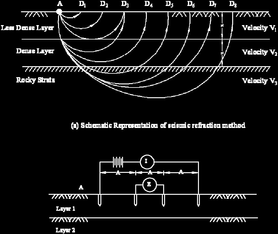
21 The seismic refraction method is based on the fact that seismic waves have different velocities in different types of soils (or rocks). The waves refract when they cross boundaries between different types of soils. If artificial impulses are produced either by detonation of explosives or mechanical blows with a heavy hammer at the ground surface or at shallow depth within a hole, these shocks generate three types of waves. In general, only compression waves i.e., longitudinal waves are observed. These waves are classified as either direct, reflected or refracted waves. Direct waves travel in approximately straight lines from the source of the impulse to the surface. Reflected or refracted waves undergo a change in direction when they encounter a boundary, a separating media of different seismic velocities. The seismic refraction method is more suited to shallow exploration for civil engineering purposes. The method starts by inducing impact or shock waves into the soil at a particular location. The shock waves are picked up by geophones. In Fig. 1.8(a), point A is the source of seismic impulse. The points D 1, D 2.. D 8 represent the locations of the geophones or detectors which are installed in a straight line. The spacings of the geophones depend on the amount of detail required and the depth of the strata being investigated. In general, the spacing must be such that the distance from D 1 to D 8 is around three to four times the depth to be investigated. The geophones are connected by cable to a central recording device. A series of detonations or impacts are produced and the arrival time of the first wave at each geophone position is recorded in turn. When the distance between source and geophone is short, the arrival time will be that of a direct wave. When the distance exceeds a certain value (depending on the thickness of the stratum), the refracted wave will be the first to be detected by the geophone. This is because the refracted wave, although longer than that of the direct wave, passes through a stratum of higher seismic velocity. A typical plot of test results for a three layer system is given in Fig. 1.8(a) with the arrival time plotted against the distance source and geophone. As in the figure, if the source-geophone spacing is more than the distance d 1 which is the distance from the source to point B, the direct wave reaches the geophone in advance of the refracted wave and the timedistance relationship is represented by a straight line AB through the origin represented by A. If on the other hand, the source geophone distance is greater than d 2, the refracted waves arrive in advance of the direct waves and the time-distance relationship is represented by another straight line BC which will have a slope different from that of AB. The slopes of

 is obtained from.eq 1.3a H = 0.85H + d 2 V V V +V The procedure is continued if there are more than three layers.")
22 the lines AB and BC are represented by 1/V 1 and 1/V 2 respectively, where V 1 and V 2 are the velocities of the upper and lower strata respectively. The general types of soils or rocks can be determined from knowledge of these velocities. The depth H 1 of the top strata (provided the thickness of the stratum is constant) can be estimated from the formula H = d 2 V V V +V The thickness of the second layer (H ) is obtained from.eq 1.3a H = 0.85H + d 2 V V V +V The procedure is continued if there are more than three layers. If the thickness of any stratum is not constant, average thickness is taken..eq 1.3b Slope of AB =

23 Slope of BC = Slope of CD =


24 1.9.2Electrical Resistivity Method Fig 1.8: Geophysical methods This method depends on differences in the electrical resistance of different soil (and rock) types. The flow of current through a soil is mainly due to electrolytic action and therefore depends on the concentration of dissolved salts in the pores. The mineral particles of soil are poor conductors of current. The resistivity of soil, therefore, decreases as both water content and concentration of salts increase. Dense clean sand above the water table, for example, would exhibit a high resistivity due to its low degree of saturation and virtual absence of dissolved salts. Saturated clay of high void ratio, on the other hand, would exhibit a low resistivity due to the relative abundance of pore water and the free ions in that water. There are several methods by which the field resistivity measurements are made. The most popular of the methods is the Wenner Method. Wenner Method The Wenner arrangement consists of four equally spaced electrodes driven approximately 20 cm into the ground as shown in Fig. 1.8(b). In this method a dc current of known magnitude is passed between the two outer (current) electrodes, thereby producing an electric field within the soil, whose pattern can be determined by the resistivities of the soils present within the field and the boundary conditions. By means of the inner electrodes the potential
25 drop E for the surface current flow lines is measured. The apparent resistivity R, is given by the equation R= 2πAE I It is customary to express A in centimeters, E in volts, I in amperes, and R in ohm-cm. The apparent resistivity represents a weighted average of true resistivity to a depth A in a large volume of soil, the soil close to the surface being more heavily weighted than the soil at greater depths. The presence of a stratum of low resistivity forces the current to flow closer to the surface resulting in a higher voltage drop and hence a higher value of apparent resistivity. The opposite is true if a stratum of low resistivity lies below a stratum of high resistivity. The method known as electrical sounding is used when the variation of resistivity with depth is required. This enables rough estimates to be made of the types and depths of strata. A series of readings are taken, the (equal) spacing of the electrodes being increased for each successive reading. However, the center of the four electrodes remains at a fixed point. As the spacing is increased, the apparent resistivity is influenced by a greater depth of soil. If the resistivity increases with the increasing electrode spacing, it can be concluded that an underlying stratum of higher resistivity is beginning to influence the readings. If increased separation produces decreasing resistivity, on the other hand, a lower resistivity is beginning to influence the readings. Apparent resistivity is plotted against spacing, preferably, on log paper. Characteristic curves for a two layer structure are shown in Fig. 1.8(b).For curve C 1 the resistivity of layer 1 is lower than that of 2; for curve C 2, layer 1 has a higher resistivity than that of layer 2. The curves become asymptotic to lines representing the true resistance R 1 and R 2 of the respective layers. Approximate layer thickness can be obtained by comparing the observed curves of resistivity versus electrode spacing with a set of standard curves. The procedure known as electrical profiling is used in the investigation of lateral variation of soil types. A series of readings is taken, the four electrodes being moved laterally as a unit for each successive reading; the electrode spacing remains constant for each reading of the series. Apparent resistivity is plotted against the center position of the four electrodes, to natural scale; such a plot can be used to locate the position of a soil of high or low resistivity. Contours of resistivity can be plotted over
26 a given area. The electrical method of exploration has been found to be not as reliable as the seismic method as the apparent resistivity of a particular soil or rock can vary over a wide range of values. Representative values of resistivity are given in Table 1.6. Table 1.6: Representative values of resistivity. The values are expressed in units of 10 3 ohm-cm (after Peck et al, 1974) Material Resistivity ohm-cm Clay and saturated silt 0-10 Sandy clay and wet silty sand Clayey sand and saturated sand Sand Gravel Weathered rock Sound rock Soil Report A report is the final document of the whole exercise of soil exploration. A report should be comprehensive, clear and to the point. Many can write reports, but only a very few can produce a good report. A report writer should be knowledgeable, practical, and pragmatic. No theory, books or codes of practice provide all the materials required to produce a good report. It is the experience of a number of years of dedicated service in the field which helps a geotechnical consultant make report writing an art. A good report should normally comprise the following: 1. A general description of the nature of the project and its importance. 2. A general description of the topographical features and hydraulic conditions of the site. 3. A brief description of the various field and laboratory tests carried out.
27 4. Analysis and discussion of the test results 5. Recommendations 6. Calculations for determining safe bearing pressures, pile loads, etc. 7. Tables containing bore logs, and other field and laboratory test results 8. Drawings which include an index plan, a site-plan, test results plotted in the form of graphs and charts, soil profiles, etc. 1.11BoreholeLog A borehole log is a record of information obtained from in situ tests and summary of laboratory tests on samples for a particular borehole. It includes description or classification of various soil / rock types at different depths with summary of essential properties including presence or otherwise of ground water table. A typical Borehole log is illustrated in Fig 1.9
28 Job No. Date: Project: Farakka STPP BH No.: 1 GL: 64.3 m Location: WB Boring method: Shell & Auger WTL: 63.0 m Supervisor: X Dia of BH: 15 cm D = disturbed sample U = undisturbed sample W = water sample N = SPT value Fig 1.9: Typical borehole log
Boreholes. Implementation. Boring. Boreholes may be excavated by one of these methods: 1. Auger Boring 2. Wash Boring 3.
 Implementation Boreholes 1. Auger Boring 2. Wash Boring 3. Rotary Drilling Boring Boreholes may be excavated by one of these methods: 4. Percussion Drilling The right choice of method depends on: Ground
Chapter 12 Subsurface Exploration
 Page 12 1 Chapter 12 Subsurface Exploration 1. The process of identifying the layers of deposits that underlie a proposed structure and their physical characteristics is generally referred to as (a) subsurface
Gotechnical Investigations and Sampling
 Gotechnical Investigations and Sampling Amit Prashant Indian Institute of Technology Gandhinagar Short Course on Geotechnical Investigations for Structural Engineering 12 14 October, 2017 1 Purpose of
ENCE 3610 Soil Mechanics. Site Exploration and Characterisation Field Exploration Methods
 ENCE 3610 Soil Mechanics Site Exploration and Characterisation Field Exploration Methods Geotechnical Involvement in Project Phases Planning Design Alternatives Preparation of Detailed Plans Final Design
Module 1 : Site Exploration and Geotechnical Investigation
 Objectives In this section you will learn the following Displacement borings Wash boring Auger boring Rotary drilling Percussion drilling Continuous sampling Boring methods of exploration The boring methods
Conventional Field Testing & Issues (SPT, CPT, DCPT, Geophysical methods)
") Conventional Field Testing & Issues (SPT, CPT, DCPT, Geophysical methods) Ajanta Sachan Assistant Professor Civil Engineering IIT Gandhinagar Conventional Field Testing 1 Field Test: In-situ shear strength
Conventional Field Testing & Issues (SPT, CPT, DCPT, Geophysical methods) Ajanta Sachan Assistant Professor Civil Engineering IIT Gandhinagar Conventional Field Testing 1 Field Test: In-situ shear strength
The process of determining the layers of natural soil deposits that will underlie a proposed structure and their physical properties is generally
 The process of determining the layers of natural soil deposits that will underlie a proposed structure and their physical properties is generally referred to as sub surface investigation 2 1 For proper
SITE INVESTIGATION 1
 SITE INVESTIGATION 1 Definition The process of determining the layers of natural soil deposits that will underlie a proposed structure and their physical properties is generally referred to as site investigation.
 UNIT I SITE INVESTIGATION AND SELECTION OF FOUNDATION Types of boring 1.Displacement borings It is combined method of sampling & boring operation. Closed bottom sampler, slit cup, or piston type is forced
B-1 BORE LOCATION PLAN. EXHIBIT Drawn By: 115G BROOKS VETERINARY CLINIC CITY BASE LANDING AND GOLIAD ROAD SAN ANTONIO, TEXAS.
 N B-1 SYMBOLS: Exploratory Boring Location Project Mngr: BORE LOCATION PLAN Project No. GK EXHIBIT Drawn By: 115G1063.02 GK Scale: Checked By: 1045 Central Parkway North, Suite 103 San Antonio, Texas 78232
SCOPE OF INVESTIGATION Simple visual examination of soil at the surface or from shallow test pits. Detailed study of soil and groundwater to a
 Lecture-5 Soil Exploration Dr. Attaullah Shah 1 Today s Lecture Purpose of Soil Exploration Different methods 1. Test trenches and Pits 2. Auger and Wash Boring 3. Rotary Drilling 4. Geophysical Methods
Pierce County Department of Planning and Land Services Development Engineering Section
 Page 1 of 7 Pierce County Department of Planning and Land Services Development Engineering Section PROJECT NAME: DATE: APPLICATION NO.: PCDE NO.: LANDSLIDE HAZARD AREA (LHA) GEOLOGICAL ASSESSMENT REPORT
LECTURE 10. Module 3 : Field Tests in Rock 3.6 GEOPHYSICAL INVESTIGATION
 LECTURE 10 3.6 GEOPHYSICAL INVESTIGATION In geophysical methods of site investigation, the application of the principles of physics are used to the study of the ground. The soil/rock have different characteristics
GEOTECHNICAL ENGINEERING II. Subject Code : 06CV64 Internal Assessment Marks : 25 PART A UNIT 1
 GEOTECHNICAL ENGINEERING II Subject Code : 06CV64 Internal Assessment Marks : 25 PART A UNIT 1 1. SUBSURFACE EXPLORATION 1.1 Importance, Exploration Program 1.2 Methods of exploration, Boring, Sounding
Foundation Engineering Prof. Mahendra Singh Department of Civil Engineering Indian Institute of Technology, Roorkee
 Foundation Engineering Prof. Mahendra Singh Department of Civil Engineering Indian Institute of Technology, Roorkee Module - 03 Lecture - 05 Field Tests Hello viewers, welcome back to the course on Foundation
GEOTECHNICAL INVESTIGATION REPORT
 GEOTECHNICAL INVESTIGATION REPORT SOIL INVESTIGATION REPORT FOR STATIC TEST FACILITY FOR PROPELLANTS AT BDL, IBRAHIMPATNAM. Graphics Designers, M/s Architecture & Engineering 859, Banjara Avenue, Consultancy
Geotechnical Testing Methods I
 Geotechnical Testing Methods I Ajanta Sachan Assistant Professor Civil Engineering IIT Gandhinagar Hiding World of Geotechnical Engg!! Foundations Shoring Tunneling Soil Exploration Geotechnical Engg Structures
Soil Mechanics Brief Review. Presented by: Gary L. Seider, P.E.
 Soil Mechanics Brief Review Presented by: Gary L. Seider, P.E. 1 BASIC ROCK TYPES Igneous Rock (e.g. granite, basalt) Rock formed in place by cooling from magma Generally very stiff/strong and often abrasive
Rotary Drilling Rotary Drilling Bits
 GE 343 SUBSURFACE EXPLORATION CH 8 Rock Drilling, Testing, and Sampling Text Ch. 7. Dr. Norbert H. Maerz Missouri University of Science and Technology (573) 341-6714 norbert@mst.edu Instructional Objectives
Instructional Objectives
 GE 343 SUBSURFACE EXPLORATION CH 8 Rock Drilling, Testing, and Sampling Text Ch. 7. Dr. Norbert H. Maerz Missouri University of Science and Technology (573) 341-6714 norbert@mst.edu Instructional Objectives
Core Barrels. Core Barrels
 Core Barrels To collect the core of the rock drilled, a device known as the core barrel is used. Core barrel retains rock core samples from drilling operations Its length varies from 0.5 to 3 m. There
EVALUATION OF STRENGTH OF SOILS AGAINST LIQUEFACTION USING PIEZO DRIVE CONE
 4 th International Conference on Earthquake Geotechnical Engineering June 25-28, 2007 Paper No. 1146 EVALUATION OF STRENGTH OF SOILS AGAINST LIQUEFACTION USING PIEZO DRIVE CONE Shun-ichi Sawada 1 ABSTRACT
Geotechnical Geotechnical Assessment
 Site Investigation Site Investigation Pile Probing Pile Probing Geotechnical Logging Geotechnical and Sampling Logging and Sampling Streetworks and Utilities Streetworks Avoidance and Utilities Avoidance
Safe bearing capacity evaluation of the bridge site along Syafrubesi-Rasuwagadhi road, Central Nepal
 Bulletin of the Department of Geology Bulletin of the Department of Geology, Tribhuvan University, Kathmandu, Nepal, Vol. 12, 2009, pp. 95 100 Safe bearing capacity evaluation of the bridge site along
The attitude he maintains in his relation to the engineer is very well stated in his own words:
 Su bsurface Soil Exploration, 53: 139 Foundation Engineering Geotechnical companies that have a history of experience in a given region usually have extensive boring logs and maps telling where the borings
How to Interpret Mining Company Drill Reports & Announcements
 How to Interpret Mining Company Drill Reports & Announcements A Simple Guide amscot Stockbroking Pty Ltd A division of State One Stockbroking Ltd (AFSL 247 100) Disclaimer: All information in this document
Minnesota Department of Transportation Geotechnical Section Cone Penetration Test Index Sheet 1.0 (CPT 1.0)
") This Cone Penetration Test (CPT) Sounding follows ASTM D 5778 and was made by ordinary and conventional methods and with care deemed adequate for the Department's design purposes. Since this sounding was
This Cone Penetration Test (CPT) Sounding follows ASTM D 5778 and was made by ordinary and conventional methods and with care deemed adequate for the Department's design purposes. Since this sounding was
Chapter 3 SUBSOIL EXPLORATION. Omitted parts: Sections & 3.24, 3.25 Examples 3.3, 3.4,3.5
 Chapter 3 SUBSOIL EXPLORATION Omitted parts: Sections 3.2-3.10 & 3.24, 3.25 Examples 3.3, 3.4,3.5 GENERAL OBSERVATION Soil does not posses a unique or linear stress-strain relationship. Soil behavior depends
Geotechnical Investigation Juneau Seawalk - Taku Fisheries to Miner s Wharf Juneau, Alaska DM&A Job No
 Duane Miller & Associates 5821 Arctic Boulevard, Suite A Anchorage, AK 99518-1654 (907) 644-3200 Fax 644-0507 Arctic & Geotechnical Engineering May 4, 2006 Tetra Tech/KCM, Inc. 1971 First Avenue Seattle,
Deep Foundations 2. Load Capacity of a Single Pile
 Deep Foundations 2 Load Capacity of a Single Pile All calculations of pile capacity are approximate because it is almost impossible to account for the variability of soil types and the differences in the
IN SITU SPECIFIC GRAVITY VS GRAIN SIZE: A BETTER METHOD TO ESTIMATE NEW WORK DREDGING PRODUCTION
 IN SITU SPECIFIC GRAVITY VS GRAIN SIZE: A BETTER METHOD TO ESTIMATE NEW WORK DREDGING PRODUCTION Nancy Case O Bourke, PE 1, Gregory L. Hartman, PE 2 and Paul Fuglevand, PE 3 ABSTRACT In-situ specific gravity
APPENDIX F CORRELATION EQUATIONS. F 1 In-Situ Tests
 APPENDIX F 1 APPENDIX F CORRELATION EQUATIONS F 1 In-Situ Tests 1. SPT (1) Sand (Hatanaka and Uchida, 1996), = effective vertical stress = effective friction angle = atmosphere pressure (Shmertmann, 1975)
Site investigation in rock
 Site investigation in rock masses Geotechnical Core Drilling & Logging Core Orientation Borehole Surveying Logging g Core Borehole Log Face Mapping Scanline Data Analysis Influence of Joints Orientation
Soil type identification and fines content estimation using the Screw Driving Sounding (SDS) data
 data") Mirjafari, S.Y. & Orense, R.P. & Suemasa, N. () Proc. th NZGS Geotechnical Symposium. Eds. GJ Alexander & CY Chin, Napier Soil type identification and fines content estimation using the Screw Driving Sounding
Mirjafari, S.Y. & Orense, R.P. & Suemasa, N. () Proc. th NZGS Geotechnical Symposium. Eds. GJ Alexander & CY Chin, Napier Soil type identification and fines content estimation using the Screw Driving Sounding
Introduction to Soil Mechanics Geotechnical Engineering-II
 Introduction to Soil Mechanics Geotechnical Engineering-II ground SIVA Dr. Attaullah Shah 1 Soil Formation Soil derives from Latin word Solum having same meanings as our modern world. From Geologist point
Week 3 : (3HL) Coverage : Typical geotechnical problems and usual application of SI methods
 Coverage : Typical geotechnical problems and usual application of SI methods") LEARNING OUTCOMES Week 3 : (3HL) Coverage : Typical geotechnical problems and usual application of SI methods Learning Outcomes : At the end of this lecture/week, the students will be able to : 1. Discuss
LEARNING OUTCOMES Week 3 : (3HL) Coverage : Typical geotechnical problems and usual application of SI methods Learning Outcomes : At the end of this lecture/week, the students will be able to : 1. Discuss
GEOTECHNICAL SITE CHARACTERIZATION
 GEOTECHNICAL SITE CHARACTERIZATION Neil Anderson, Ph.D. Professor of Geology and Geophysics Richard W. Stephenson, P.E., Ph.D. Professor of Civil, Architectural and Environmental Engineering University
Soil Dynamics Prof. Deepankar Choudhury Department of Civil Engineering Indian Institute of Technology, Bombay
 Soil Dynamics Prof. Deepankar Choudhury Department of Civil Engineering Indian Institute of Technology, Bombay Module - 4 Dynamic Soil Properties Lecture - 23 Cyclic Stress Ratio, Evaluation of CRR, Correction
Early Exploration Permit Activity Information
 Early Exploration Permit Activity Information Activities That Require an Early Exploration Permit: Line cutting that is a width greater than 1.5 metres Mechanized stripping of a total surface area of greater
 Photo 1 - Southerly view across 2700 parking lot toward existing building. Multi-residential building borders western side of property in upper right of view. Photo 2 - Southerly view across 2750 parking
 Project: ITHACA-TOMPKINS REGIONAL AIRPORT EXPANSION Project Location: ITHACA, NY Project Number: 218-34 Key to Soil Symbols and Terms TERMS DESCRIBING CONSISTENCY OR CONDITION COARSE-GRAINED SOILS (major
Early Exploration Plan Activity Information
 Early Exploration Plan Activity Information Activities That Require an Early Exploration Plan: Line cutting that is a width of 1.5 metres or less; Geophysical surveys on the ground requiring the use of
Minnesota Department of Transportation Geotechnical Section Cone Penetration Test Index Sheet 1.0 (CPT 1.0)
") This Cone Penetration Test (CPT) Sounding follows ASTM D 778 and was made by ordinary and conventional methods and with care deemed adequate for the Department's design purposes. Since this sounding was
This Cone Penetration Test (CPT) Sounding follows ASTM D 778 and was made by ordinary and conventional methods and with care deemed adequate for the Department's design purposes. Since this sounding was
Geotechnical Indications Of Eastern Bypass Area In Port Harcourt, Niger Delta
 Geotechnical Indications Of Eastern Bypass Area In Port Harcourt, Niger Delta Warmate Tamunonengiyeofori Geostrat International Services Limited, Rivers State, Nigeria www.geostratinternational.com info@geostratinternational.com,
Liquefaction Resistance and Internal Erosion Potential of Non-Plastic Silty Sand
 Liquefaction Resistance and Internal Erosion Potential of Non-Plastic Silty Sand Jing-Wen CHEN 1, Wei F. LEE 2, Chun-Chi CHEN 3 1 Professor, Department of Civil Engineering, National Chen-Kung University
Geotechnical Subsoil Investigation for the Design of Water Tank Foundation
 International Journal of Scientific and Research Publications, Volume 4, Issue 3, March 2014 1 Geotechnical Subsoil Investigation for the Design of Water Tank Foundation * Ngerebara Owajiokiche Dago, **
REPORT OF SUBSURFACE EXPLORATION
 REPORT OF SUBSURFACE EXPLORATION GRAND RIVER DAM AUTHORITY HULBERT 69 KV SWITCHING STATION S. 440 Road Hulbert, Cherokee County, Oklahoma ENERCON PROJECT NO. GRDA006 MARCH 7, 2012 PREPARED FOR: C/O ENERCON
ISC 5 SELF-BORING PRESSUREMETER TESTS AT THE NATIONAL FIELD TESTING FACILITY, BALLINA 5 9 SEPT 2016
 ISC 5 5 9 SEPT 2016 SELF-BORING PRESSUREMETER TESTS AT THE NATIONAL FIELD TESTING FACILITY, BALLINA Fillippo Gaone James Doherty Susan Gourvenec Centre for Offshore Foundation Systems, UWA School of Civil,
(C) Global Journal of Engineering Science and Research Management
 Global Journal of Engineering Science and Research Management") GEOTECHNCIAL ASSESSMENT OF PART OF PORT HARCOURT, NIGER DELTA FOR STRUCTURAL ANALYSIS Warmate Tamunonengiyeofori Geostrat International Services Limited, www.geostratinternational.com. *Correspondence
GEOTECHNCIAL ASSESSMENT OF PART OF PORT HARCOURT, NIGER DELTA FOR STRUCTURAL ANALYSIS Warmate Tamunonengiyeofori Geostrat International Services Limited, www.geostratinternational.com. *Correspondence
INTRODUCTION TO STATIC ANALYSIS PDPI 2013
 INTRODUCTION TO STATIC ANALYSIS PDPI 2013 What is Pile Capacity? When we load a pile until IT Fails what is IT Strength Considerations Two Failure Modes 1. Pile structural failure controlled by allowable
Liquefaction and Foundations
 Liquefaction and Foundations Amit Prashant Indian Institute of Technology Gandhinagar Short Course on Seismic Design of Reinforced Concrete Buildings 26 30 November, 2012 What is Liquefaction? Liquefaction
KDOT Geotechnical Manual Edition. Table of Contents
 KDOT Geotechnical Manual 2007 Edition The KDOT Geotechnical Manual is available two volumes. Both volumes are very large electronic (pdf) files which may take several minutes to download. The table of
This document downloaded from vulcanhammer.net vulcanhammer.info Chet Aero Marine
 This document downloaded from vulcanhammer.net vulcanhammer.info Chet Aero Marine Don t forget to visit our companion site http://www.vulcanhammer.org Use subject to the terms and conditions of the respective
Cone Penetration Testing in Geotechnical Practice
 Cone Penetration Testing in Geotechnical Practice Table Of Contents: LIST OF CONTENTS v (4) PREFACE ix (2) ACKNOWLEDGEMENTS xi (1) SYMBOL LIST xii (4) CONVERSION FACTORS xvi (6) GLOSSARY xxii 1. INTRODUCTION
Chapter 7 Permeability and Seepage
 Permeability and Seepage - N. Sivakugan (2005) 1 7.1 INTRODUCTION Chapter 7 Permeability and Seepage Permeability, as the name implies (ability to permeate), is a measure of how easily a fluid can flow
General. DATE December 10, 2013 PROJECT No TO Mary Jarvis Urbandale/Riverside South Development Corporation
 DATE December 10, 201 PROJECT No. 10-1121-0260- TO Mary Jarvis Urbandale/Riverside South Development Corporation CC Justin Robitaille, Urbandale Jonathan Párraga, J.L. Richards & Associates Limited FROM
Interpretation of Pile Integrity Test (PIT) Results
 Results") Annual Transactions of IESL, pp. 78-84, 26 The Institution of Engineers, Sri Lanka Interpretation of Pile Integrity Test (PIT) Results H. S. Thilakasiri Abstract: A defect present in a pile will severely
Annual Transactions of IESL, pp. 78-84, 26 The Institution of Engineers, Sri Lanka Interpretation of Pile Integrity Test (PIT) Results H. S. Thilakasiri Abstract: A defect present in a pile will severely
Measurement of effective stress shear strength of rock
 Measurement of effective stress shear strength of rock R. A. Failmezger, P.E., F. ASCE In-Situ Soil Testing, L.C., Lancaster, Virginia USA D. J. White, Ph. D., P.E. Iowa State University, Ames, Iowa USA
June 9, R. D. Cook, P.Eng. Soils Engineer Special Services Western Region PUBLIC WORKS CANADA WESTERN REGION REPORT ON
 PUBLIC WORKS CANADA WESTERN REGION REPORT ON GEOTECHNICAL INVESTIGATION PROPOSED MARTIN RIVER BRIDGE MILE 306.7 MACKENZIE HIGHWAY Submitted by : R. D. Cook, P.Eng. Soils Engineer Special Services Western
Cyclic Behavior of Sand and Cyclic Triaxial Tests. Hsin-yu Shan Dept. of Civil Engineering National Chiao Tung University
 Cyclic Behavior of Sand and Cyclic Triaxial Tests Hsin-yu Shan Dept. of Civil Engineering National Chiao Tung University Causes of Pore Pressure Buildup due to Cyclic Stress Application Stress are due
Site Investigations and Geotechnical Risk For Underground Construction Greg Raines, PE
 August 14, 2017 Site Investigations and Geotechnical Risk For Underground Construction Greg Raines, PE Gregory.Raines@Stantec.com Develop Preliminary Geologic / Geotech Conceptual Model for the Project
*** ***! " " ) * % )!( & ' % # $. 0 1 %./ +, - 7 : %8% 9 ) 7 / ( * 7 : %8% 9 < ;14. " > /' ;-,=. / ١
 * % )!( & ' % # $. 0 1 %./ +, - 7 : %8% 9 ) 7 / ( * 7 : %8% 9 < ;14. > /' ;-,=. / ١") ١ ******!" #$ % & '!( ) % * ") +,-./ % 01. 3 ( 4 56 7/4 ) 8%9 % : 7 ;14 < 8%9 % : *7./ = ;-, >/'." Soil Permeability & Seepage ٢ Soil Permeability- Definition ٣ What is Permeability? Permeability is the
١ ******!" #$ % & '!( ) % * ") +,-./ % 01. 3 ( 4 56 7/4 ) 8%9 % : 7 ;14 < 8%9 % : *7./ = ;-, >/'." Soil Permeability & Seepage ٢ Soil Permeability- Definition ٣ What is Permeability? Permeability is the
From - To 0,00-4,90 4,90-6,40 6,40-8,60 8,60-9,60 9,60-10,50 10,50-12,00 12,00-14,80 14,80-15,80 15,80-19,30 19, ,00
 Závěrka 12,Praha 6,169 00 Log of Boring BH1 Project ID: 2018_A-017 Annex no.: A.1G Drilling equipment: Hütte 202 TF Location: Prague 12 Overall depth: 2 m Borehole position: Date start: 22.11.2017 Foreman:
BAUER MeBo Sea Bed Drill Rig
 BAUER MeBo Sea Bed Drill Rig Spotlights BAUER Maritime Experiences 1993 Diamond deposit exploration with a BC cutter in water depth of 160 m (South Africa) Atlantic Ocean 2005 Drilling inside of a monopile
(THIS IS ONLY A SAMPLE REPORT OR APPENDIX OFFERED TO THE USERS OF THE COMPUTER PROGRAM
 C A U T I O N!! (THIS IS ONLY A SAMPLE REPORT OR APPENDIX OFFERED TO THE USERS OF THE COMPUTER PROGRAM EQLique&Settle2. THE AUTHOR IS HEREBY RELEASED OF ANY LIABILITY FOR ANY INCORRECT USE OF THIS SAMPLE
SOIL MECHANICS AND APPLIED FOUNDATION ENGINEERING FUNDAMENTAL FACTS OF SOIL BEHAVIOR
 SOIL MECHANICS AND APPLIED FOUNDATION ENGINEERING The Subsurface is Unknown to many and Blind Guesswork cannot be used to Determine the Character and Behavior of the Underlying Soil Conditions. FUNDAMENTAL
ATTACHMENT A PRELIMINARY GEOTECHNICAL SUMMARY
 ATTACHMENT A PRELIMINARY GEOTECHNICAL SUMMARY Kevin M. Martin, P.E. KMM Geotechnical Consultants, LLC 7 Marshall Road Hampstead, NH 0384 603-489-6 (p)/ 603-489-8 (f)/78-78-4084(m) kevinmartinpe@aol.com
8.1. What is meant by the shear strength of soils? Solution 8.1 Shear strength of a soil is its internal resistance to shearing stresses.
 8.1. What is meant by the shear strength of soils? Solution 8.1 Shear strength of a soil is its internal resistance to shearing stresses. 8.2. Some soils show a peak shear strength. Why and what type(s)
NEW DOWN-HOLE PENETROMETER (DHP-CIGMAT) FOR CONSTRUCTION APPLICATIONS
 FOR CONSTRUCTION APPLICATIONS") NEW DOWN-HOLE PENETROMETER (DHP-CIGMAT) FOR CONSTRUCTION APPLICATIONS 1 2 C. Vipulanandan 1, Ph.D., M. ASCE and Omer F. Usluogullari 2 Chairman, Professor, Director of Center for Innovative Grouting Materials
NEW DOWN-HOLE PENETROMETER (DHP-CIGMAT) FOR CONSTRUCTION APPLICATIONS 1 2 C. Vipulanandan 1, Ph.D., M. ASCE and Omer F. Usluogullari 2 Chairman, Professor, Director of Center for Innovative Grouting Materials
Appendix J. Geological Investigation
 Appendix J Geological Investigation Appendix J Geological Environment Table of Contents Page 1 INTRODUCTION...J-1 1.1 Purpose of the Investigation...J-1 1.2 Scope of the Investigation...J-1 2 METHODO OF
SHEAR STRENGTH OF SOIL
 SHEAR STRENGTH OF SOIL Necessity of studying Shear Strength of soils : Soil failure usually occurs in the form of shearing along internal surface within the soil. Shear Strength: Thus, structural strength
Civil Engineering, Surveying and Environmental Consulting WASP0059.ltr.JLS.Mich Ave Bridge Geotech.docx
 2365 Haggerty Road South * Canton, Michigan 48188 P: 734-397-3100 * F: 734-397-3131 * www.manniksmithgroup.com August 29, 2012 Mr. Richard Kent Washtenaw County Parks and Recreation Commission 2330 Platt
REPORT OF GEOTECHNICAL INVESTIGATION FOR CONSTRUCTION OF AIIMS AT GUNTUR, ANDHRA PRADESH
 REPORT OF GEOTECHNICAL INVESTIGATION FOR CONSTRUCTION OF AIIMS AT GUNTUR, ANDHRA PRADESH REPORT NO : GT 1764 CLIENT: DEPUTY GENERAL MANAGER (CIVIL) HSCC (INDIA) LTD. (A Govt. Of India Enterprise) (CONSULTANTS
THE PREDICTION OF FINAL SETTLEMENT FROM 1D-CONSOLIDATION TEST: A CASE STUDY
 THE PREDICTION OF FINAL SETTLEMENT FROM 1D-CONSOLIDATION TEST: A CASE STUDY Mohd Fakhrurrazi Bin Ishak 1 and Mohd Hazreek Bin Zainal Abidin 2 1 Faculty of Civil Engineering and Environmental engineering,
Predicting Settlement and Stability of Wet Coal Ash Impoundments using Dilatometer Tests
 Predicting Settlement and Stability of Wet Coal Ash Impoundments using Dilatometer Tests Chris Hardin, P.E. CH2M Hill, Charlotte, North Carolina, E-mail: Chris.Hardin@ch2m.com Roger Failmezger, P.E., F.
GEOTECHNICAL INVESTIGATION REPORT INFRASTRUCTURE PVT LTD
 GEOTECHNICAL INVESTIGATION REPORT Client : TAEIN CONSTRUCTION & INFRASTRUCTURE PVT LTD Office address : Flat No.104, A -Wing,1st floor,gloria Park, Paranjape Scheme, Bavdhan Khurd, Chandni Chowk, Pune
patersongroup Design for Earthquakes Consulting Engineers May 19, 2016 File: PG3733-LET.01
 patersongroup May 19, 2016 File: PG3733-LET.01 Hydro Ottawa Limited c/o Cresa Toronto 170 University Avenue, Suite 1 Toronto, Ontario M5H 3B3 Attention: Ms. Barbara Wright Consulting Engineers 154 Colonnade
Geotechnical Engineering Report
 Geotechnical Engineering Report Turner Turnpike Widening Polecat Creek Bridge (Bridge A) June 1, 2016 Terracon Project No. 04155197 Prepared for: Garver, LLC Prepared by: Terracon Consultants, Inc. TABLE
Correlations between soil parameters and penetration testing results
 1 A 1 6 Correlations between soil parameters and penetration testing results Corrélation entre paramètres du sol et résultats de sondage J. FORMAZIN, Director, VEB SBK Wasserbau, KB Baugrund Berlin, Berlin,
CHAPTER 3.0 DRILLING AND SAMPLING OF SOIL AND ROCK
 HAPTER 3.0 DRILLING AND SAMPLING OF SOIL AND ROK This chapter describes the equipment and procedures commonly used for the drilling and sampling of soil and rock. The methods addressed in this chapter
M E M O R A N D U M. Mr. Jonathan K. Thrasher, P.E., Mr. Ian Kinnear, P.E. (FL) PSI
 PSI") M E M O R A N D U M TO: FROM: Mr. Mark Schilling Gulf Interstate Engineering Mr. Jonathan K. Thrasher, P.E., Mr. Ian Kinnear, P.E. (FL) PSI DATE: November 11, 2014 RE: Summary of Findings Geotechnical
M E M O R A N D U M TO: FROM: Mr. Mark Schilling Gulf Interstate Engineering Mr. Jonathan K. Thrasher, P.E., Mr. Ian Kinnear, P.E. (FL) PSI DATE: November 11, 2014 RE: Summary of Findings Geotechnical
CONTENTS. 1. GeneralsG Field Investigation WorkG Laboratory Testing Work Surface Soil Description-- 7.
 CONTENTS Page 1. GeneralsG 4 2. Field Investigation WorkG 4 3. Laboratory Testing Work--- 5 4. Surface Soil Description-- 7 Appendix A Borehole Location Plan 11 Soil Profile-- 15 Bore Logs--=---- 18 Appendix
Date: April 2, 2014 Project No.: Prepared For: Mr. Adam Kates CLASSIC COMMUNITIES 1068 E. Meadow Circle Palo Alto, California 94303
 City of Newark - 36120 Ruschin Drive Project Draft Initial Study/Mitigated Negative Declaration Appendix C: Geologic Information FirstCarbon Solutions H:\Client (PN-JN)\4554\45540001\ISMND\45540001 36120
Highway Subsurface Exploration
 Highway Subsurface Exploration D. G. S hurig, Research A ssistant E. J. Yoder, Research E ngineer Joint Highway Research Project Purdue University Introduction This paper pertains to the operation and
SI Planning & Laboratory Testing for Hill-Site Development
 SI Planning & Laboratory Testing for Hill-Site Development 21 April 2009 IEM Penang Ir. Tan Yean Chin G&P Geotechnics Sdn Bhd Cameron Highlands, 1961 Genting Highland Tower 1993 Bukit Antarabangsa, 1999
Chapter (12) Instructor : Dr. Jehad Hamad
 Instructor : Dr. Jehad Hamad") Chapter (12) Instructor : Dr. Jehad Hamad 2017-2016 Chapter Outlines Shear strength in soils Direct shear test Unconfined Compression Test Tri-axial Test Shear Strength The strength of a material is the
Chapter (12) Instructor : Dr. Jehad Hamad 2017-2016 Chapter Outlines Shear strength in soils Direct shear test Unconfined Compression Test Tri-axial Test Shear Strength The strength of a material is the
(Refer Slide Time: 02:18)
") Geology and Soil Mechanics Prof. P. Ghosh Department of Civil Engineering Indian Institute of Technology Kanpur Lecture 40 Shear Strength of Soil - C Keywords: Shear strength of soil, direct shear test,
Geology and Soil Mechanics Prof. P. Ghosh Department of Civil Engineering Indian Institute of Technology Kanpur Lecture 40 Shear Strength of Soil - C Keywords: Shear strength of soil, direct shear test,
Mitigation of Liquefaction Potential Using Rammed Aggregate Piers
 ASCE 2011 557 Mitigation of Liquefaction Potential Using Rammed Aggregate Piers R.W. Rudolph, M. ASCE, G.E. 1, B. Serna, M. ASCE, P.E. 2, and T. Farrell, M. ASCE, G.E. 3 1 Principal Consultant, ENGEO,
Manual on Subsurface Investigations National Highway Institute Publication No. FHWA NHI Federal Highway Administration Washington, DC
 Manual on Subsurface Investigations National Highway Institute Publication No. FHWA NHI-01-031 Federal Highway Administration Washington, DC Geotechnical Site Characterization July 2001 by Paul W. Mayne,
APPENDIX A. Borehole Logs Explanation of Terms and Symbols
 APPENDIX A Borehole Logs Explanation of Terms and Symbols Page 153 of 168 EXPLANATION OF TERMS AND SYMBOLS The terms and symbols used on the borehole logs to summarize the results of field investigation
CPT Data Interpretation Theory Manual
 CPT Data Interpretation Theory Manual 2016 Rocscience Inc. Table of Contents 1 Introduction... 3 2 Soil Parameter Interpretation... 5 3 Soil Profiling... 11 3.1 Non-Normalized SBT Charts... 11 3.2 Normalized
Common Exploration Methods.
 Common Exploration Methods. The following list contains the most common methods which a company with a mineral prospecting licence in Northern Ireland might use to carry out a mineral prospecting programme.
Applicability Of Standard Penetration Tests To Estimate Undrained Shear Strength Of Soils Of Imphal.
 International Journal of Engineering Technology Science and Research March 217 Applicability Of Standard Penetration Tests To Estimate Undrained Shear Strength Of Soils Of Imphal. Ngangbam Bulbul Singh,
Chapter 5 Shear Strength of Soil
 Page 5 Chapter 5 Shear Strength of Soil. The internal resistance per unit area that the soil mass can offer to resist failure and sliding along any plane inside it is called (a) strength (b) shear strength
The CPT in unsaturated soils
 The CPT in unsaturated soils Associate Professor Adrian Russell (UNSW) Mr David Reid (Golder Associates) Prof Nasser Khalili (UNSW) Dr Mohammad Pournaghiazar (UNSW) Dr Hongwei Yang (Uni of Hong Kong) Outline
APPENDIX C. Borehole Data
 APPENDIX C Borehole Data MAJOR DIVISIONS SOIL CLASSIFICATION CHART SYMBOLS GRAPH LETTER TYPICAL DESCRIPTIONS ADDITIONAL MATERIAL
Geotechnical Engineering Report
 Geotechnical Engineering Report Turner Turnpike Widening Bridge B Bridge Crossing: South 257 th West Avenue Creek County, Oklahoma June 1, 2016 Terracon Project No. 04155197 Prepared for: Garver, LLC Tulsa,
APPENDIX C HYDROGEOLOGIC INVESTIGATION
 Figure B-5.7 Figure B-5.8 Preliminary Geotechnical and Environmental Report Appendix C Hydrogeologic Investigation APPENDIX C HYDROGEOLOGIC INVESTIGATION December 21, 2011 WESTSIDE SUBWAY EXTENSION PROJECT
Soils. Technical English - I 10 th week
 Technical English - I 10 th week Soils Soil Mechanics is defined as the branch of engineering science which enables an engineer to know theoretically or experimentally the behavior of soil under the action
Limited Geotechnical Engineering Evaluation Classroom Additions Albany County Campus Laramie, Wyoming
 Limited Geotechnical Engineering Evaluation Classroom Additions Albany County Campus 2300 Missile Drive, Cheyenne, Wyoming 82001 Phone 307-635-0222 www.stratageotech.com Limited Geotechnical Engineering