Chapter 3 SUBSOIL EXPLORATION. Omitted parts: Sections & 3.24, 3.25 Examples 3.3, 3.4,3.5
|
|
|
- Gwen Cameron Allison
- 6 years ago
- Views:
Transcription
1 Chapter 3 SUBSOIL EXPLORATION Omitted parts: Sections & 3.24, 3.25 Examples 3.3, 3.4,3.5
2 GENERAL OBSERVATION Soil does not posses a unique or linear stress-strain relationship. Soil behavior depends up on the pressure, time and environment. Soil at every location is essentially different. Nearly in all the cases, the mass of soil involved is underground and cannot be seen entirely, but must be evaluated on the basis of small size samples, obtained from isolated locations. Most soils are very sensitive to disturbance from sampling and thus the behavior measured by a lab test may be unlike that of in situ soil.
3 SUBSOIL EXPLORATION Natural soil deposits are not homogeneous, elastic, or isotropic. In some places, the stratification of soil deposits may change greatly within a short horizontal distance. For foundation design and construction work, one must know the actual soil stratification at a given site, the laboratory test results of the soil samples obtained from various depths, and the observations made during the construction of other structures built under similar conditions. For most major structures, adequate subsoil exploration at the construction site must be conducted.


4 DEFINITION OF SUBSOIL EXPLORATION The process of determining the layers of natural soil deposits that will underlie a proposed structure and their physical properties
5 PURPOSE OF SUBSOIL EXPLORATION The purpose of subsurface exploration is to obtain information that will aid the geotechnical engineer in: 1. Determining the nature of soil at the site and its stratification. 2. Selecting the type and depth of foundation suitable for a given structure. 3. Evaluating the load-bearing capacity of the foundation. 4. Estimating the probable settlement of a structure. 5. Determining potential foundation problems (e.g., expansive soil, collapsible soil, sanitary landfill, and so on). 6. Determining the location of water table. 7. Predicting the lateral earth pressure for structures such as retaining walls, sheet pile, and braced cuts. 8. Establishing construction methods for changing subsoil conditions.
6 SUBSURFACE EXPLORATION PROGRAM A soil exploration program for a given structure can be divided broadly into three phases: I. Collection of Preliminary Information II. Reconnaissance (Field Trip) III. Site Investigation
7 I. Collection of Preliminary Information This step includes obtaining information regarding the type of structure to be built and its general use. For the construction of building: The approximate column loads and their spacing. Local building-codes. Basement requirement. For the construction of bridge: The length of their spans. The loading on piers and abutments. It also includes obtaining information regarding the general topography and type of soil to be encountered near and around the proposed site which can be obtained from Saudi Geological Survey and other sources. هيئة المساحة الجيولوجية السعودية
8 II. RECONNAISSANCE (FIELD TRIP) The engineer should always make a visual inspection (field trip) of the site to obtain information about: The general topography of the site, the possible existence of drainage ditches, and other materials present at the site. Evidence of creep of slopes and deep, wide shrinkage cracks at regularly spaced intervals may be indicative of expansive soil. Soil stratification from deep cuts, such as those made for the construction of nearby highways and railroads. The type of vegetation at the site, which may indicate the nature of the soil. Groundwater levels, which can be determined by checking nearby wells. The type of construction nearby and the existence of any cracks in walls (indication for settlement) or other problems. The nature of the stratification and physical properties of the soil nearby also can be obtained from any available soil-exploration reports on existing structures.
 Making test boreholes.")
9 III. SITE INVESTIGATION This phase consists of: Planning (adopting steps for site investigation, and future vision for the site) Making test boreholes. Collecting soil samples at desired intervals for visual observation and laboratory tests.


10 SITE INVESTIGATION Soil Boring: Test Pits Auger Boring Test Pits: Open excavation ( deep & approximate 1 m wide) Suitable for near surface evaluation, sampling and testing Visual inspection Excavated by hand or machine For small projects where foundation level < 2 m Block samples For preliminary investigation It is relatively fast and inexpensive
11 NUMBER OF BORING Determining the number of boring: There is no hard-and-fast rule exists for determining the number of borings are to be advanced. For most buildings, at least one boring at each corner and one at the center should provide a start. Spacing can be increased or decreased, depending on the condition of the subsoil. If various soil strata are more or less uniform and predictable, fewer boreholes are needed than in nonhomogeneous soil strata. Approximate Spacing of Boreholes Type of project Multistory building One-story industrial plants Highways Residential subdivision Dams and dikes Spacing (m)
 m: The required number of boreholes = 5 boreholes (one at each corner and one at the center) as mentioned previously.")
12 EXAMPLE In practice: number of boreholes and the depth of each borehole will be identified according to the type of project and the subsoil on site. Example for a 5 story residential building with dimensions of (40 x 70) m: The required number of boreholes = 5 boreholes (one at each corner and one at the center) as mentioned previously. The figure shows the distribution of boreholes on the land
13 DEPTH OF BORING Determining the depth of boring: The approximate required minimum depth of the borings should be predetermined. The estimated depths can be changed during the drilling operation, depending on the subsoil encountered (e.g., Rock). To determine the approximate required minimum depth of boring, engineers may use the rules established by the American Society of Civil Engineers (ASCE 1972): 1. Determine the net increase in effective stress (Δσ ) under a foundation with depth. 2.Estimate the variation of the vertical effective stress (σo ) with depth. 3. Determine the depth (D = D 1 ) at which the effective increase (q = estimated net stress on the foundation). 4. Determine the depth (D = D 2 ) at which 5. Determine the depth (D = D 3 ) which is the distance from the lower face of the foundation to bedrock (if encountered). 6. Choose the smaller of the three depths (D 1, D 2, and D 3 ) is the approximate required minimum depth of boring. After determining the value of (D) as explained above, the final depth of boring (from the ground surface to the calculated depth) is: Because the drilling will start from the ground surface. Δσ σo
14 DEPTH OF BORING
15 DEPTH OF BORING
16 DEPTH OF BORING Determining the value of vertical effective stress (σo ): The value of (σo ) always calculated from the ground surface to the required depth, as previously discussed in (CE382-CHAPTER 9). Determining the increase in vertical effective stress(δσ ): The value of (Δσ ) always calculated from the lower face of the foundation as discussed previously in (CE382-CHAPTER 10). An alternative approximate method can be used (2:1 Method). According to this method, the value of (Δσ ) at depth (D) is: D P A P (B D)(L D) P=the load applied on the foundation (KN). A=the area of the stress distribution at depth (D). Note that the above equation is based on the assumption that the stress from the foundation spreads out with a vertical-to-horizontal slope of 2:1.
17 DEPTH OF BORING If the foundation is circular, the value of (Δσ ) at depth (D) can be determined as following: P D Area at depth (D) P D (B D) 2 4 P=the load applied on the foundation (KN). B=diameter of the foundation(m).
18 EXAMPLE Site investigation is to be made for a structure of 100m length and 70m width. The soil profile is shown below, if the structure is subjected to 200 KN/m 2 What is the approximate depth of borehole. (Assume γ w =10KN/m 3 ). γ sat =18KN/m 3
 at which o D ( - )D sat w 2 0.05(8*D 2) (18-10)D 0.40*D 2 1.4*10 A P 6 D (70 D 2)(100 D 2) 6 1.4*10 0.40*D (70 D 2)(100 D 2) D2 101.")
19 SOLUTION P=200 (100 70)= KN 1. Determination of the depth D 1 ) at which the effective increase 1.4 *10 A P 6 D (70 D 1)(100 D 1) D1 180 m Determination of the depth (D = D 2 ) at which o D ( - )D sat w (8*D 2) (18-10)D 0.40*D 2 1.4*10 A P 6 D (70 D 2)(100 D 2) 6 1.4* *D (70 D 2)(100 D 2) D m 2 8*D 2 2 D1 180 m & D m &D3 D m (the smallest) 130 m
20 METHODS OF BORING The boring methods are used for exploration at greater depths where direct methods fail. They provide both disturbed as well as undisturbed samples depending upon the method of boring. In selecting the boring method for a particular job, consideration should be made for the following: The materials to be encountered and the relative efficiency of the various boring methods in such materials The available facility and accuracy with which changes in the soil and ground water conditions can be determined Possible disturbance of the material to be sampled
21 METHODS OF BORING The different types of boring methods are: 1. Auger boring 2. Continuous sampling 3.Wash boring 4. Rotary drilling 5. Percussion drilling

22 AUGER BORING 1. Hand auger, two types: Posthole Auger Helical Auger Depth 3-5 m Disturbed samples Small structures, highways, 2. Deeper boreholes: Portable power-driven helical augers
23 AUGER BORING This method is fast and economical, using simple, light, flexible and inexpensive instruments for large to small holes. It is very suitable for soft to stiff cohesive soils and also can be used to determine ground water table. Soil removed by this method is disturbed but it is better than wash boring, percussion or rotary drilling. This method of boring is not suitable for: Very hard or cemented soils Very soft soils Fully saturated cohesionless soils

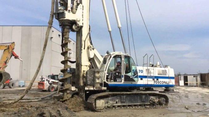
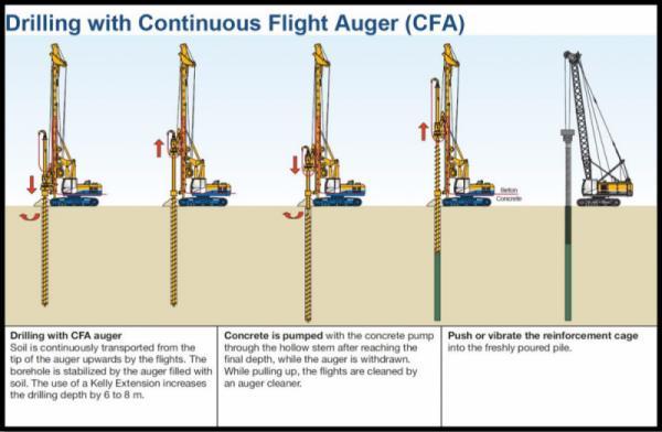
24 CONTINUOUS-FLIGHT AUGERS The sampling operation advances the borehole and the boring is accomplished entirely by taking samples continuously. Boreholes up to a depth of m. They are available in sections of about 1-2 m with either a solid or hollow stem with different diameters. Hollow-stem augers have a distinct advantage over solid-stem augers in that they do not have to be removed frequently for sampling or other tests. The tip of the auger is attached to a cutter head. The casing is used to prevent the caving in soils. The flights of the augers bring the loose soil from the bottom of the hole to the surface. The driller can detect changes in the type of soil by noting changes in the speed and sound of drilling.
25 CONTINUOUS-FLIGHT AUGERS
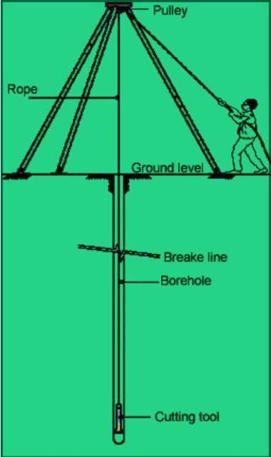
26 WASH BORING It is a popular method due to the use of limited equipment. The advantage of this method is the use of inexpensive and easily portable handling and drilling equipment. First an open hole is formed on the ground so that the soil sampling or rock drilling operation can be done below the hole. The hole is advanced by chopping and twisting action of the light bit. Cutting is done by forced water and water jet under pressure through the rods operated inside the hole. A pipe of 5 cm diameter is held vertically and filled with water using horizontal lever arrangement and by the process of suction and application of pressure, soil slurry comes out of the tube and pipe goes down. This can be done up to a depth of 8m 10m. Just by noting the change of color of soil coming out with the change of soil character can be identified by any experienced person. It gives completely disturbed sample and is not suitable for very soft soil, fine to medium grained cohesionless soil and in cemented soil.

27 WASH BORING
28 ROTARY DRILLING It is useful in case of highly resistant strata. It is related to finding out the rock strata and also to access the quality of rocks from cracks, fissures and joints. It can be used also in sands and silts. The bore holes are advanced in depth by rotary method which is similar to wash boring technique. A heavy string of the drill rod is used for choking action. The broken rock or soil fragments are removed by circulating water or drilling mud pumped through the drill rods and bit up through the bore hole from which it is collected in a settling tank for recirculation. If the depth is small and the soil stable, water alone can be used. However, drilling fluids are useful as they serve to stabilize the bore hole. Drilling mud is slurry of bentonite in water. The drilling fluid causes stabilizing effect to the bore hole partly due to higher specific gravity as compared with water and partly due to formation of mud cake on the sides of the hole. As the stabilizing effect is imparted by these drilling fluids no casing is required if drilling fluid is used. This method is suitable for boring holes of diameter 10 cm, or more preferably 15 to 20 cm in most of the rocks. It is uneconomical for holes less than 10 cm diameter. The depth of various strata can be detected by inspection of cuttings.

29 ROTARY DRILLING
30 PERCUSSION DRILLING In case of hard soils or soft rock, auger boring or wash boring cannot be employed. For such strata, percussion drilling is usually adopted. Advancement of hole is done by alternatively lifting and dropping a heavy drilling bit which is attached to the lower end of the drilling bit which is attached to the cable. Addition of sand increases the cutting action of the drilling bit in clays. whereas, when coarse cohesionless soil is encountered, clay might have to be added to increase the carrying capacity of slurry. After the carrying capacity of the soil is reached, churn bit is removed and the slurry is removed using bailers and sand pumps. Change in soil character is identified by the composition of the outgoing slurry. The stroke of bit varies according to the ground condition. Generally, it is cm in depth with rate of drops/min. It is not economical for hole of diameter less than 10cm. It can be used in most of the soils and rocks and can drill any material. One main disadvantage of this process is that the material at the bottom of the hole is disturbed by heavy blows of the chisel and hence it is not possible to get good quality undisturbed samples. It cannot detect thin strata as well.
31 PERCUSSION DRILLING
32 SOIL SAMPLING Need for Soil Sampling A satisfactory design of a foundation depends upon the accuracy with which the various soil parameters required for the design are obtained. The accuracy of the soil parameters depends upon the accuracy with which representative soil samples are obtained from the field. Sampling is carried out in order that soil and rock description, and laboratory testing can be carried out. Laboratory tests typically consist of: Index tests (for example, specific gravity, water content) Classification tests (for example, Atterberg s limit tests on clayey soil) Tests to determine engineering design parameters (for example strength, compressibility, and permeability).
33 SOIL SAMPLING Factors to be considered while sampling soil Samples should be representative of the ground from which they are taken. They should be large enough to contain representative particles sizes, fabric, and fissuring and fracturing. They should be taken in such a way that they have not lost fractions of the in situ soil (for example, coarse or fine particles). Where strength and compressibility tests are planned, they should be subject to as little disturbance as possible.

34 SOIL SAMPLING Non-Representative Soil Samples Non-representative soil samples are those in which neither the in-situ soil structure, moisture content nor the soil particles are preserved. They cannot be used for any tests as the soil particles either gets mixed up or some particles may be lost. Samples that are obtained through wash boring or percussion drilling are examples of non-representative samples
35 SOIL SAMPLING Representative Soil Samples There are two types of samples: Disturbed Soil Samples Undisturbed Soil Samples
36 DISTURBED SOIL SAMPLES Disturbed soil samples are those in which the in-situ soil structure and moisture content are lost, but the soil particles are intact. They are representative. They can be used for the following types of laboratory soil tests: grain size analysis liquid and plastic limits specific gravity compaction tests moisture content organic content determination The major equipment used to obtain disturbed samples is Split Spoon a steel tube with D i = mm D o = 50.8mm


37 SPLIT SPOON SAMPLING D i = mm D o = mm

38 SCRAPER BUCKET If soil deposits are sand mixed with pebbles (split spoon with a spring core catcher may not be possible because pebbles may prevent the springs from closing. A scraper bucket is used to obtain disturbed representative samples. The scraper bucket is driven in the soil and rotated, the scrapings from the side fall into the bucket.
39 UNDISTURBED SOIL SAMPLES Undisturbed soil samples are those in which the in-situ soil structure and moisture content are preserved. They are representative and also intact. These are used for the following types of laboratory soil tests: Consolidation tests. Hydraulic Conductivity tests. Shear Strength tests. These samples are more complex and expensive, and they are suitable for clays, however in sand, it is very difficult to obtain undisturbed samples. The major equipment used to obtain undisturbed sample is Shelby tube (thin-walled tube) and piston sampler.
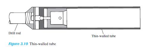
40 THIN-WALLED TUBE (SHELBY TUBE) D i = mm D o = mm
41 PISTON SAMPLER When undisturbed samples are very soft or larger than 76.2 mm in diameter, they tend to fall out of the sampler Piston samplers are used in such conditions It consists of a thin-walled tube with a piston. Initially, the piston closes the end of the tube. The sampler is lowered to the bottom of the borehole, and the tube is pushed into the soil hydraulically, past the piston. Then the pressure is released through a hole in the piston rod. Samples obtained using this sampler are less disturbed than those obtained by Shelby tubes.
42 DEGREE OF DISTURBANCE If we want to obtain a soil sample from any site, the degree of disturbance for a soil sample is usually expressed as: 2 2 Do Di AR (%) (100) 2 D o =outside diameter of the sampling tube. D i =inside diameter of the sampling tube. If (A R ) 10% the sample is undisturbed If (A R )>10% the sample is disturbed D i For a standard split-spoon sampler (which sampler for disturbed samples): A R 2 (50.8) (34.93) 2 (34.93) 2 (100) 111.5% 10% disturbed For a Shelby tube (thin-walled tube) -- sampler for undisturbed samples A R 2 (50.8) (47.63) 2 (47.63) 2 (100) 13.75% 10% undisturbe d
43 GROUNDWATER Why do you always measure groundwater? Calculation of effective stress Can impact the bearing capacity of shallow foundations Can impact the pressures against retaining walls Impacts the capacity of pile foundations Impacts the in-situ permeability Impacts construction that may be below groundwater table How do you measure groundwater levels? In the borehole immediately after and 24 hours In a piezometer (simple well) Pore water pressure transducers (data over time) piezometer
44 IN-SITU TESTS The ground is tested in-place by instruments that are inserted in or penetrate the ground. In-situ tests are normally associated with tests for which a borehole either is unnecessary or is only an incidental part of the overall test procedure, required only to permit insertion of the testing tool or equipment. Improvements in apparatus, instrumentation, and technique of deployment, data acquisition and analysis procedure have been significant.
45 IN-SITU TESTS Advantages Tests are carried out in place in the natural environment without sampling disturbance, which can cause detrimental effects and modifications to stresses, strains, drainage, fabric and particle arrangement. Continuous profiles of stratigraphy and engineering properties/ characteristics can be obtained. Detection of planes of weakness and defects are more likely and practical. Methods are usually fast, repeatable, produce large amounts of information and are cost effective. Tests can be carried out in soils that are either impossible or difficult to sample without the use of expensive specialized methods. A large volume of soil may be tested than is normally practicable for laboratory testing. This may be more representative of the soil mass.
46 IN-SITU TESTS Disadvantages Samples are not obtained; the soil tested cannot be positively identified. The exception to this is the SPT in which a sample, although disturbed, is obtained. The fundamental behavior of soils during testing is not well understood. Drainage conditions during testing are not known. Consistent, rational interpretation is often difficult and uncertain. The stress path imposed during testing may bear no resemblance to the stress path induced by full-scale engineering structure. Most push-in devices are not suitable for a wide range of ground conditions. Some disturbance is imparted to the ground by the insertion or installation of the instrument. There is usually no direct measurement of engineering properties. Empirical correlations usually have to be applied to interpret and obtain engineering properties and designs
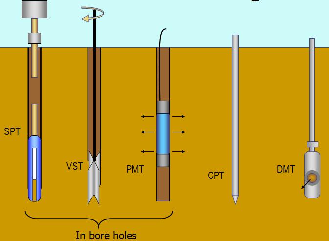
47 IN-SITU TESTS Standard Penetration Test (SPT) Vane shear test (VST) Cone Penetration Test (CPT) The Flat Dilatometer Test (DMT) The Pressuremeter Test (PMT) The Plate Load Test (PLT) Later

48 IN-SITU TESTS
49 STANDARD PENETRATION TEST (SPT) This test is one of the most important soil tests for geotechnical engineers because it s widely used in calculating different factors. It is used as an indicator of relative density and stiffness of granular soils as well as an indicator of consistency in a wide range of other ground. Methods have been developed to apply SPT results to a wide range of geotechnical applications including shallow and deep foundations. The main standard for the SPT is the American Society for Testing and Materials (ASTM D ). Aim: To perform standard penetration to obtain the penetration resistance (N-value) along the depth at a given site. Advantages of SPT: Simple and rugged Low cost Obtain a sample Can be performed in most soil types Disadvantages of SPT: Disturbed sample (index tests only) Crude number (N value) Not applicable in soft clays and silts High variability and uncertainty.
 Tripod head with hook Pulley Guide pipe assembly Standard split spoon sampler A drill rod for extending the test to deeper depths Heavy duty post hole auger (100-150 mm diameter) Heavy duty helical")
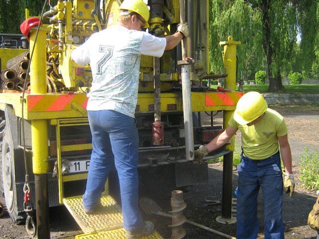
50 STANDARD PENETRATION TEST (SPT) Equipment & Apparatus Tripod (to give a clear height of about 4 m; one of the legs of the tripod should have ladder to facilitate a person to reach tripod head.) Tripod head with hook Pulley Guide pipe assembly Standard split spoon sampler A drill rod for extending the test to deeper depths Heavy duty post hole auger ( mm diameter) Heavy duty helical auger Heavy duty auger extension rods Sand bailer Rope (about 15 m long & strong enough to lift 63.5 kg load repeatedly) A light duty rope to operate sand bailer Chain pulley block Casing pipes Casing couplings Casing clamps *A straight edge (50 cm) Measuring tapes *Tool box
51 SPT (PROCEDURE) 1. Determine the required number and depth of boreholes in the site. 2. The sampler used in SPT test is (Standard Split Spoon). 3. Using drilling machine, 1.5m are drilled. 4. The drilling machine is removed and the sampler is lowered to the bottom of the hole. 5. The sampler is driven into the soil by hammer blows to the top of the drill rod, the standard weight of the hammer is N (63.48 Kg), and for each blow, the hammer drops a distance of 76.2 cm. 6. The number of blows required for a spoon penetration of three 15 cm intervals are recorded. 7. The first 15 cm drive is considered as seating load and is ignored. 8. The number of blows required for the last two intervals are added to give the Standard Penetration Number (N) at that depth. 9. The sampler is then withdrawn and the soil sample recovered from the tube is placed in a glass bottle and transported to laboratory. 10. Using the drilling machine to drill another 1.5m and then repeat the above steps for each 1.5 m till reaching the specified depth of borehole. 11. Take the average for (N) value from each 1.5 m to obtain the final Standard Penetration Number.

52 STANDARD PENETRATION TEST (SPT)
53 STANDARD PENETRATION TEST (SPT) No. Procedure Its Affect 1 Inadequate cleaning of the SPT is only partially made in original soil. Sludge may be trapped in the borehole sampler and compressed as the sampler is driven, increasing the blow 2 Not seating the sampler spoon on undisturbed material 3 Driving of the sample spoon above the bottom of the casing 4 Failure to maintain sufficient hydrostatic head in boring count. This may also prevent sample recovery. Incorrect N value obtained N values are increased in sands and reduced in cohesive soils. The water table in the borehole must be at least equal to the piezometric level in the sand, otherwise the sand at the bottom of the borehole may be transformed into a loose state. 5 Attitude of operators Blow counts for the same soil using the same rig can vary, depending on who is operating the rig, and perhaps the mood of operator and time of drilling. 6 Overdriving the sampler Higher blow counts usually result from overdriven sampler 7 Sampler plugged by gravel Higher blow counts usually result when gravel plugs sampler, resistance of loose sand could be highly overestimated. 8 Plugged casing High N values may be recorded for loose sand when sampling below ground water table. Hydrostatic pressure causes sand to rise and plug casing. 9 Over washing ahead of casing Low blow count may result for dense sand since sand is loosened by over washing. 10 Drilling method Drilling technique (e.g. cased holes vs mud stabilized hole) may result in different N values for the same soil.
54 STANDARD PENETRATION TEST (SPT) No. Procedure Its Affect 11 Not using the standard hammer drop Energy delivered per blow is not uniform. European countries have adopted an automatic trip hammer not currently in use in North America. 12 Free fall of the drive weight is not attained Using more than 1-1/2 turns of rope around the drum and/or using wire cable will restrict the fall of the drive weight. 13 Not using correct weight Driller frequently supplies drive hammers with weight varying from the standard by as much as 5kg. 14 Weight does not strike the Impact energy is reduced, increasing N values. drive cap concentrically 15 Not using a guide rod Incorrect N value obtained 16 Incorrect drilling procedures The SPT was originally developed from wash boring techniques. Drilling procedures which seriously disturb the soil will affect the N value, e.g. drilling with cable tool equipment. 17 Using drill holes that are too large Holes greater than 10 cm in diameter are not recommended. Use of larger diameters may result in decreases in the blow count. 18 Inadequate supervision Frequently a sampler will be impeded by gravel or cobbles causing a sudden increase in blow count; this is not recognized by an inexperienced observer. Accurate recording of drilling, sampling and depth is always required. 19 Improper logging of soils Not describing the sample correctly 20 Using too large a pump Too high a pump capacity will loosen the soil at the base of the hole causing a decrease in blow count.
55 STANDARD PENETRATION TEST (SPT) PRECAUTIONS 1.Results of standard penetration test are not reproducible in cohesionless soil below water level unless care is taken to maintain the water level inside the borehole always slightly above the natural groundwater level. If the water level in the borehole is lower than natural groundwater level, quick conditions develop and soil becomes loose. 2.The split spoon sampler must be in good condition with no excessive damage or wear and tear to the cutting shoe. 3.The drill rods should be the right size and not too heavy or too light. The drill rods also should not be bent. 4.The fall of the weight should be free. Friction in the pulley or guide rod, or braking action by crew, or interference due to hoist rope can result in higher than actual blow count.
56 9. Careless work on the part of drilling crew, improper and incorrect counting of blows and recording must be avoided. STANDARD PENETRATION TEST (SPT) PRECAUTIONS 5. The height of free fall of weight must be 750 mm. It is obvious that the change in the height of fall will result in a value different from the actual value for N. 6. The bottom of borehole must be properly cleaned before seating the split spoon sampler. Otherwise the test will be carried out in the loose and disturbed soil at the bottom of the bore hole. 7. If casing is used in borehole it must not be driven ahead of the level at which SPT is being carried out. Otherwise the SPT will be carried out in a soil plug enclosed at the bottom of the casing. 8.The rate of delivery of the blows should not be too fast.
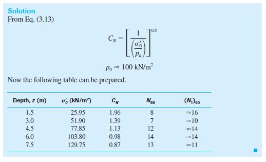
57 Variations of η H η B η S η R are summarized in table 2.5 (page 84). SPT (CORRECTION TO N VALUE) There are several factors contribute to the variation of the standard penetration number (N) at a given depth for similar profiles. Among these factors are the SPT hammer efficiency, borehole diameter, sampling method, and rod length. In the field, the magnitude of hammer efficiency can vary from 30 to 90%, the standard practice now is to express the N-value to an average energy ratio of 60% (N 60 ), so correcting for field procedures is required as following: N=measured penetration number. N 60 =standard penetration number, corrected for the field conditions. η H =hammer efficiency (%). η B =correction for borehole diameter. η S =sampler correction. η R =correction for rod length.
58 SPT (N 60 CORRELATIONS) N 60 can be used for calculating some important parameters such as: Consistency Index (CI) Undrained shear strength (C u ) Overconsolidation ratio (OCR) Relative Density (D r ) Angle of internal friction (ϕ) Modulus of Elasticity (E s )
59 SPT (N 60 CORRELATIONS)

60 EXAMPLE 3.1

61 EXAMPLE 3.2
62 VANE SHEAR TEST (VST) Vane shear test is used to evaluate the in-situ undrained shear strength (c u ) of soft to stiff clays and silts. Both peak and remolded strengths can be measured and their ratio is termed soil sensitivity. Advantages of VST: Simple test and equipment Long history of use in practice Disadvantages of VST: Limited application to soft to stiff clays and silts Slow and time-consuming Raw c u values need (empirical) correction

63 VANE SHEAR TEST (VST) VST consists of inserting a simple four-bladed vane into either clay or silt and rotating the device about a vertical axis and measuring the torque. Limit equilibrium is used to relate the measured torque to the undrained shear strength mobilized. Both peak and remolded strengths can be measured. A selection of vanes is available in terms of size, shape and configuration, depending on the consistency and strength of the soils. The standard vane (ASTM D 2573) has a rectangular geometry with a blade height to diameter ratio of 2. This figure shows typical field vane A standard 10 cm 2 cone penetrometer is shown for scale.
64 VANE SHEAR TEST (VST) Test Procedure Test procedures are outlined in ASTM D The test is often carried out by pushing the vane into the soil from the bottom of a borehole and the vane should be pushed at least four borehole diameters below the base of the borehole to avoid disturbance from drilling. The test can also be carried out using direct-push equipment pushing from the ground surface when there are no hard layers. Within 5 minutes after insertion, rotation should be carried out at a constant rate of 6 degrees per minute (0.1 o /s) with frequent measurements of the mobilized torque. Depending on the type of equipment used, there is the potential for friction to develop along the push rods. This friction needs to be either minimized or accounted for in the measurements.
")
65 VANE SHEAR TEST (VST)
")
66 VANE SHEAR TEST (VST)
 assumes a uniform distribution of shear stresses both top and bottom and along the blades and a vane with a height-to-width ratio H/D =")
67 VANE SHEAR TEST (VST) Undrained Shear Strength The conventional interpretation to obtain the VST undrained shear strength from the maximum torque (T max ) assumes a uniform distribution of shear stresses both top and bottom and along the blades and a vane with a height-to-width ratio H/D = 2:
).")
68 VANE SHEAR TEST (VST) Sensitivity After the peak c u (peak) is obtained, the vane is rotated quickly through 10 complete revolutions and the test repeated to measure the remolded values(c u (remolded)). The sensitivity, S t is then: S t = c u (peak) / c u (remolded)
69 VANE SHEAR TEST (VST) Vane Correction Factor Since there is no unique value for the undrained shear strength of fine grained soils, it is common that the VST strength is corrected prior to application in stability analyses involving embankments on soft ground, bearing capacity and excavations in soft ground. C u (corrected) = l C u (VST) Where l is an empirical correction factor that has been related to plasticity index (PI) and void ratio. Correlation between c u and Preconsolidation pressure and overconsolidation ratio.
70 Disadvantage of CPT: High capital investment Requires skilled operators No soil sample Penetration can be restricted in gravel/cemented layers CONE PENETRATION TEST (CPT) The Cone Penetration Test (CPT)) has extensive applications in a wide range of soils. Although the CPT is limited primarily to softer soils, with modern larger pushing equipment and more robust cones, the CPT can be performed in stiff to very stiff soils, and in some cases soft rock. Two types: 1. Mechanical friction-cone penetrometer 2. Electric friction-cone penetrometer Advantages of CPT: Fast and continuous profiling Repeatable and reliable data (not operator-dependent) Economical and productive Strong theoretical basis for interpretation
 Electric")

71 CONE PENETRATION TEST (CPT) Electric friction-cone penetrometer Mechanical friction-cone penetrometer

72 CONE PENETRATION TEST (CPT) In the Cone Penetration Test (CPT), a cone on the end of a series of rods is pushed into the ground at a constant rate and continuous measurements are made of the resistance to penetration of the cone and of a surface sleeve. The total force acting on the cone, Q c, divided by the projected area of the cone, A c, produces the cone resistance, q c. The total force acting on the friction sleeve, F s, divided by the surface area of the friction sleeve, A s, produces the sleeve friction, f s. In a piezocone, pore pressure is also measured.

73 CONE PENETRATION TEST (CPT) Cone penetrometers come in a range of sizes with the 10 cm 2 and 15 cm 2 probes the most common and specified in most standards. Figure shows a range of cones from a mini-cone at 2 cm 2 to a large cone at 40 cm 2. The mini cones are used for shallow investigations, whereas the large cones can be used in gravely soils.


74 CONE PENETRATION TEST (CPT) Pushing equipment for on land applications generally consist of specially built units that are either truck or track mounted. CPT s can also be carried out using an anchored drill-rig. Truck mounted 25 ton CPT unit Small anchored drill-rig unit CPT inside buildings or limited access

75 CONE PENETRATION TEST (CPT) Real-Time readings in computer screen
76 q c CORRELATIONS q c can be used for calculating some important parameters such as: Relative Density (D r ). Angle of internal friction (ϕ). N 60 Undrained shear strength (C u ) Preconsolidation pressure Overconsolidation ratio (OCR)
77 q c CORRELATIONS
78 q c CORRELATIONS
79 PRESSUREMETER TEST (PMT) The pressuremeter test can be used to evaluate the stress-strain response of a wide range of soils and rock. It consists of a probe with three cells. The top and bottom ones are guard cells and the middle is the measuring cell. There are three basic types of pressuremeter devices, Pre-bored, Self-bored and Full-displacement, each with different abilities and challenges. Advantages of PMT: Strong theoretical basis for interpretation Tests large volume of ground Disadvantages of PMT: Complicated equipment and procedures Requires skilled operator Time consuming and expensive Equipment can be easily damaged
80 PRESSUREMETER TEST (PMT)
81 PRESSUREMETER TEST (PMT) c u ( p l N p p o ) c p p u l o Undrainedshear strength of Limit pressure Insitu total horizontalstress a clay N p 1 ln( E 3c p u )
82 FLAT PLATE DILATOMETER TEST (DMT) The flat plate dilatometer test (DMT) can be used to estimate a wide range of geotechnical parameters in primarily softer soils. Advantages of DMT: Simple and robust Repeatable and reliable data (not operator-dependent) Economical Disadvantage of DMT: Difficult to push into dense and hard materials Weak theoretical basis for interpretation No soil sample Penetration can be restricted in gravel/cemented layers

83 FLAT PLATE DILATOMETER TEST (DMT)

84 FLAT PLATE DILATOMETER TEST (DMT)

85 FLAT PLATE DILATOMETER TEST (DMT)
86 FLAT PLATE DILATOMETER TEST (DMT)
87 FLAT PLATE DILATOMETER TEST (DMT)

88 CORING OF ROCKS

89 CORING OF ROCKS
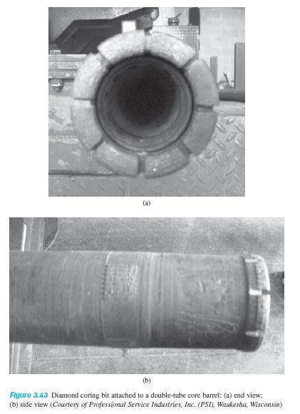
90 CORING OF ROCKS Core barrel samplers are originally designed to sample rock. Single tube sampler The core barrel of the sampler rotates and this poses the possibility of disturbing the sample by shearing the sample along certain weak planes. Moreover, the cored samples are subjected to erosion and disturbance by the drilling fluid. The rock cores obtained can be highly disturbed and fractured because of torsion. Double tube samplers The tube samplers do not rotate with the core barrels and the samplers are not protected against the drilling fluid. The logging of samples presents difficulty for highly fractured rock.

91 CORING OF ROCKS

92 BORING LOGS

93 BORING LOGS
94 GEOPHYSICAL EXPLORATION Although boring and test pits provide definite results but they are time consuming and expensive. Subsurface conditions are known only at the bore or test pit location. The subsurface conditions between the boring need to be interpolated or estimated. Geophysical methods are more quick and cheaper. They provide thorough coverage of the entire area. The results of Geophysical testing however are less definitive and require subjective interpretation. Therefore both methods are important. In case geophysical testing in major in scope, few borings and sampling will be required for accurate determination of soil properties. If boring is major in scope then few geophysical lines will be required to know the conditions in-between the borings.
95 GEOPHYSICAL TEST METHODS Advantages Many geophysical tests are non-invasive and thus offer significant benefits in cases where conventional drilling, testing, and sampling are difficult (e.g., deposits of gravel, talus deposits) or where potentially contaminated soils may occur in the subsurface. In general, geophysical testing covers a relatively large area, thus providing the opportunity to characterize large areas with few tests. It is particularly well-suited to projects that have large longitudinal extent compared to lateral extent (such as for new highway construction). Geophysical measurement assesses the characteristics of soil and rock at very small strains, typically on the order of percent thus providing information on truly elastic properties. For the purpose of obtaining information on the subsurface, geophysical methods are relatively inexpensive when considering cost relative to the relatively large areas over which information can be obtained.
96 GEOPHYSICAL TEST METHODS Disadvantages Most methods work best for situations in which there is a large difference in stiffness between adjacent subsurface units. It is difficult to develop good stratigraphic profiling if the general stratigraphy consists of hard material over soft material Results are generally interpreted qualitatively and therefore useful results can only be obtained by an experienced engineer or geologist familiar with the particular testing method. Specialized equipment is required (compared to more conventional subsurface exploration tools).
97 GEOPHYSICAL TEST METHODS There are a number of different geophysical in-situ tests that can be used for stratigraphic information and in the determination of engineering properties. The most common methods are: Three methods 1.Seismic Refraction Survey 2.Cross-Hole Seismic Survey 3.Electrical Resistivity Survey
98 SEISMIC REFRACTION SURVEY Useful in obtaining preliminary information about the thickness of the layering of various soils and the depth to rock or hard soil. It is conducted by impacting the surface and observing the first arrival of the disturbance (stress wave) at several other points. The impact can be created by a hammer blow or by a small explosive charge. The first arrival of disturbance waves at various points can be recorded by geophones. A graph of travel time versus distance is established Two types of stress waves: o P waves (plane waves) o S waves (shear waves) P faster than S.

99 SEISMIC REFRACTION SURVEY

100 SEISMIC REFRACTION SURVEY

101 SEISMIC REFRACTION SURVEY
102 SEISMIC REFRACTION SURVEY Advantages : It is fast and not hindered by the presence of boulders Equipment is lightweight and can be carried in the field. Two persons are enough Disadvantages : It can not detect a subsurface layer whose sonic velocity is slower than that of the layer above (peat, soft clay, ) Wrong interpretation of the subsurface materials when the soil is saturated and the ground water table is not detected.


 are recorded by a")
103 CROSS-HOLE SEISMIC SURVEY To find the shear modulus of the soil Two holes are drilled into the ground, spacing L distance A vertical impulse is created at the bottom of one hole by means of an impulse rod. The shear waves (generated) are recorded by a vertically sensitive transducer.
104 ELECTRICAL RESISTIVITY SURVEY To obtain information about the stratification of the subsurface Different soils have different electrical resistivity Saturated soils very low resistivity Dry soils and rock high resistivity It consists of : Four electrodes are driven into the ground, spaced equally along a straight line (Wenner method). Two electrodes supply current to the ground, the other two detect the current between the exciting electrodes After each measurement, the spacing d can be expanded to penetrate greater depths. Plot vs. d can be obtained, from which the thickness of various layers can be estimated.

105 ELECTRICAL RESISTIVITY SURVEY
106 ELECTRICAL RESISTIVITY SURVEY Advantages : It is fast and low cost It can detect underlying layer whose resistivity are either higher of lower than overlying layers Disadvantages : Sensitive to variations in both soil conditions and electrode placement Can not distinguish between soft and stiff clays.
107 GEOTECHNICAL REPORT Upon completion of the geotechnical investigation and analysis, the information and findings must be compiled in a standard report format. The report serves as the permanent record of all geotechnical data known to be pertinent to the project and is referred to throughout the design, construction, and service life of the project. The data and recommendations are typically compiled in a Geotechnical Report. The intent of the Geotechnical Report is to present the data collected in a clear manner, to draw conclusions from the data, and to make recommendations for the geotechnical aspects of the project. The primary clients that use the report are roadway designers, Bridge Engineers, construction personnel, and contractors.

108 SUBSOIL EXPLORATION REPORT
Boreholes. Implementation. Boring. Boreholes may be excavated by one of these methods: 1. Auger Boring 2. Wash Boring 3.
 Implementation Boreholes 1. Auger Boring 2. Wash Boring 3. Rotary Drilling Boring Boreholes may be excavated by one of these methods: 4. Percussion Drilling The right choice of method depends on: Ground
Module 1 : Site Exploration and Geotechnical Investigation
 Objectives In this section you will learn the following Displacement borings Wash boring Auger boring Rotary drilling Percussion drilling Continuous sampling Boring methods of exploration The boring methods
SITE INVESTIGATION 1
 SITE INVESTIGATION 1 Definition The process of determining the layers of natural soil deposits that will underlie a proposed structure and their physical properties is generally referred to as site investigation.
Chapter 12 Subsurface Exploration
 Page 12 1 Chapter 12 Subsurface Exploration 1. The process of identifying the layers of deposits that underlie a proposed structure and their physical characteristics is generally referred to as (a) subsurface
ENCE 3610 Soil Mechanics. Site Exploration and Characterisation Field Exploration Methods
 ENCE 3610 Soil Mechanics Site Exploration and Characterisation Field Exploration Methods Geotechnical Involvement in Project Phases Planning Design Alternatives Preparation of Detailed Plans Final Design
Gotechnical Investigations and Sampling
 Gotechnical Investigations and Sampling Amit Prashant Indian Institute of Technology Gandhinagar Short Course on Geotechnical Investigations for Structural Engineering 12 14 October, 2017 1 Purpose of
SCOPE OF INVESTIGATION Simple visual examination of soil at the surface or from shallow test pits. Detailed study of soil and groundwater to a
 Lecture-5 Soil Exploration Dr. Attaullah Shah 1 Today s Lecture Purpose of Soil Exploration Different methods 1. Test trenches and Pits 2. Auger and Wash Boring 3. Rotary Drilling 4. Geophysical Methods
 UNIT I SITE INVESTIGATION AND SELECTION OF FOUNDATION Types of boring 1.Displacement borings It is combined method of sampling & boring operation. Closed bottom sampler, slit cup, or piston type is forced
The process of determining the layers of natural soil deposits that will underlie a proposed structure and their physical properties is generally
 The process of determining the layers of natural soil deposits that will underlie a proposed structure and their physical properties is generally referred to as sub surface investigation 2 1 For proper
GEOTECHNICAL ENGINEERING II. Subject Code : 06CV64 Internal Assessment Marks : 25 PART A UNIT 1
 GEOTECHNICAL ENGINEERING II Subject Code : 06CV64 Internal Assessment Marks : 25 PART A UNIT 1 1. SUBSURFACE EXPLORATION 1.1 Importance, Exploration Program 1.2 Methods of exploration, Boring, Sounding
Conventional Field Testing & Issues (SPT, CPT, DCPT, Geophysical methods)
") Conventional Field Testing & Issues (SPT, CPT, DCPT, Geophysical methods) Ajanta Sachan Assistant Professor Civil Engineering IIT Gandhinagar Conventional Field Testing 1 Field Test: In-situ shear strength
Conventional Field Testing & Issues (SPT, CPT, DCPT, Geophysical methods) Ajanta Sachan Assistant Professor Civil Engineering IIT Gandhinagar Conventional Field Testing 1 Field Test: In-situ shear strength
Manual on Subsurface Investigations National Highway Institute Publication No. FHWA NHI Federal Highway Administration Washington, DC
 Manual on Subsurface Investigations National Highway Institute Publication No. FHWA NHI-01-031 Federal Highway Administration Washington, DC Geotechnical Site Characterization July 2001 by Paul W. Mayne,
KDOT Geotechnical Manual Edition. Table of Contents
 KDOT Geotechnical Manual 2007 Edition The KDOT Geotechnical Manual is available two volumes. Both volumes are very large electronic (pdf) files which may take several minutes to download. The table of
IN SITU TESTING TECHNOLOGY FOR FOUNDATION & EARTHQUAKE ENGINEERING. Wesley Spang, Ph.D., P.E. AGRA Earth & Environmental, Inc.
 IN SITU TESTING TECHNOLOGY FOR FOUNDATION & EARTHQUAKE ENGINEERING Wesley Spang, Ph.D., P.E. AGRA Earth & Environmental, Inc. Portland, Oregon In situ testing of soil, which essentially consists of evaluating
Advanced Foundation Engineering
 2013 Advanced Foundation Engineering Prof.T.G. Sitharam Indian Institute of Science, Bangalore CHAPTER 1: Soil Exploration 1.1 Introduction 1.2 Boring of Holes 1.2.1 Auger Method 1.2.1.1 Hand Operated
SI Planning & Laboratory Testing for Hill-Site Development
 SI Planning & Laboratory Testing for Hill-Site Development 21 April 2009 IEM Penang Ir. Tan Yean Chin G&P Geotechnics Sdn Bhd Cameron Highlands, 1961 Genting Highland Tower 1993 Bukit Antarabangsa, 1999
APPENDIX F CORRELATION EQUATIONS. F 1 In-Situ Tests
 APPENDIX F 1 APPENDIX F CORRELATION EQUATIONS F 1 In-Situ Tests 1. SPT (1) Sand (Hatanaka and Uchida, 1996), = effective vertical stress = effective friction angle = atmosphere pressure (Shmertmann, 1975)
Soils. Technical English - I 10 th week
 Technical English - I 10 th week Soils Soil Mechanics is defined as the branch of engineering science which enables an engineer to know theoretically or experimentally the behavior of soil under the action
Week 3 : (3HL) Coverage : Typical geotechnical problems and usual application of SI methods
 Coverage : Typical geotechnical problems and usual application of SI methods") LEARNING OUTCOMES Week 3 : (3HL) Coverage : Typical geotechnical problems and usual application of SI methods Learning Outcomes : At the end of this lecture/week, the students will be able to : 1. Discuss
LEARNING OUTCOMES Week 3 : (3HL) Coverage : Typical geotechnical problems and usual application of SI methods Learning Outcomes : At the end of this lecture/week, the students will be able to : 1. Discuss
B-1 BORE LOCATION PLAN. EXHIBIT Drawn By: 115G BROOKS VETERINARY CLINIC CITY BASE LANDING AND GOLIAD ROAD SAN ANTONIO, TEXAS.
 N B-1 SYMBOLS: Exploratory Boring Location Project Mngr: BORE LOCATION PLAN Project No. GK EXHIBIT Drawn By: 115G1063.02 GK Scale: Checked By: 1045 Central Parkway North, Suite 103 San Antonio, Texas 78232
The attitude he maintains in his relation to the engineer is very well stated in his own words:
 Su bsurface Soil Exploration, 53: 139 Foundation Engineering Geotechnical companies that have a history of experience in a given region usually have extensive boring logs and maps telling where the borings
Geotechnical Testing Methods I
 Geotechnical Testing Methods I Ajanta Sachan Assistant Professor Civil Engineering IIT Gandhinagar Hiding World of Geotechnical Engg!! Foundations Shoring Tunneling Soil Exploration Geotechnical Engg Structures
SHEAR STRENGTH OF SOIL
 Soil Failure Criteria SHEAR STRENGTH OF SOIL Knowledge about the shear strength of soil important for the analysis of: Bearing capacity of foundations, Slope stability, Lateral pressure on retaining structures,
GEOTECHNICAL SITE CHARACTERIZATION
 GEOTECHNICAL SITE CHARACTERIZATION Neil Anderson, Ph.D. Professor of Geology and Geophysics Richard W. Stephenson, P.E., Ph.D. Professor of Civil, Architectural and Environmental Engineering University
Geotechnical Geotechnical Assessment
 Site Investigation Site Investigation Pile Probing Pile Probing Geotechnical Logging Geotechnical and Sampling Logging and Sampling Streetworks and Utilities Streetworks Avoidance and Utilities Avoidance
Cone Penetration Testing in Geotechnical Practice
 Cone Penetration Testing in Geotechnical Practice Table Of Contents: LIST OF CONTENTS v (4) PREFACE ix (2) ACKNOWLEDGEMENTS xi (1) SYMBOL LIST xii (4) CONVERSION FACTORS xvi (6) GLOSSARY xxii 1. INTRODUCTION
Core Barrels. Core Barrels
 Core Barrels To collect the core of the rock drilled, a device known as the core barrel is used. Core barrel retains rock core samples from drilling operations Its length varies from 0.5 to 3 m. There
This document downloaded from vulcanhammer.net vulcanhammer.info Chet Aero Marine
 This document downloaded from vulcanhammer.net vulcanhammer.info Chet Aero Marine Don t forget to visit our companion site http://www.vulcanhammer.org Use subject to the terms and conditions of the respective
Site Investigations and Geotechnical Risk For Underground Construction Greg Raines, PE
 August 14, 2017 Site Investigations and Geotechnical Risk For Underground Construction Greg Raines, PE Gregory.Raines@Stantec.com Develop Preliminary Geologic / Geotech Conceptual Model for the Project
Rotary Drilling Rotary Drilling Bits
 GE 343 SUBSURFACE EXPLORATION CH 8 Rock Drilling, Testing, and Sampling Text Ch. 7. Dr. Norbert H. Maerz Missouri University of Science and Technology (573) 341-6714 norbert@mst.edu Instructional Objectives
How to Interpret Mining Company Drill Reports & Announcements
 How to Interpret Mining Company Drill Reports & Announcements A Simple Guide amscot Stockbroking Pty Ltd A division of State One Stockbroking Ltd (AFSL 247 100) Disclaimer: All information in this document
GEOTECHNICAL INVESTIGATION REPORT
 GEOTECHNICAL INVESTIGATION REPORT SOIL INVESTIGATION REPORT FOR STATIC TEST FACILITY FOR PROPELLANTS AT BDL, IBRAHIMPATNAM. Graphics Designers, M/s Architecture & Engineering 859, Banjara Avenue, Consultancy
Pierce County Department of Planning and Land Services Development Engineering Section
 Page 1 of 7 Pierce County Department of Planning and Land Services Development Engineering Section PROJECT NAME: DATE: APPLICATION NO.: PCDE NO.: LANDSLIDE HAZARD AREA (LHA) GEOLOGICAL ASSESSMENT REPORT
SASKATCHEWAN STRATIGRAPHY GLACIAL EXAMPLE BOULDERS IN GLACIAL DEPOSITS
 SASKATCHEWAN STRATIGRAPHY GLACIAL EXAMPLE BOULDERS IN GLACIAL DEPOSITS 51 SASKATCHEWAN STRATIGRAPHY GLACIAL SURFICIAL STRATIFIED DEPOSITS 52 SASKATCHEWAN STRATIGRAPHY GLACIAL EXAMPLE OF SEDIMENT DEPOSITION
Instructional Objectives
 GE 343 SUBSURFACE EXPLORATION CH 8 Rock Drilling, Testing, and Sampling Text Ch. 7. Dr. Norbert H. Maerz Missouri University of Science and Technology (573) 341-6714 norbert@mst.edu Instructional Objectives
A. V T = 1 B. Ms = 1 C. Vs = 1 D. Vv = 1
 Geology and Soil Mechanics 55401 /1A (2002-2003) Mark the best answer on the multiple choice answer sheet. 1. Soil mechanics is the application of hydraulics, geology and mechanics to problems relating
Geology and Soil Mechanics /1A ( ) Mark the best answer on the multiple choice answer sheet.
 Mark the best answer on the multiple choice answer sheet.") Geology and Soil Mechanics 55401 /1A (2003-2004) Mark the best answer on the multiple choice answer sheet. 1. Soil mechanics is the application of hydraulics, geology and mechanics to problems relating
Geology and Soil Mechanics 55401 /1A (2003-2004) Mark the best answer on the multiple choice answer sheet. 1. Soil mechanics is the application of hydraulics, geology and mechanics to problems relating
June 9, R. D. Cook, P.Eng. Soils Engineer Special Services Western Region PUBLIC WORKS CANADA WESTERN REGION REPORT ON
 PUBLIC WORKS CANADA WESTERN REGION REPORT ON GEOTECHNICAL INVESTIGATION PROPOSED MARTIN RIVER BRIDGE MILE 306.7 MACKENZIE HIGHWAY Submitted by : R. D. Cook, P.Eng. Soils Engineer Special Services Western
Soil Mechanics Brief Review. Presented by: Gary L. Seider, P.E.
 Soil Mechanics Brief Review Presented by: Gary L. Seider, P.E. 1 BASIC ROCK TYPES Igneous Rock (e.g. granite, basalt) Rock formed in place by cooling from magma Generally very stiff/strong and often abrasive
Enhanced In-Situ Testing for Geotechnical Site Characterization. Graduate Course CEE 6423
 Enhanced In-Situ Testing for Geotechnical Site Characterization SPT, VST, DMT, PMT, CHT, DHT, CPT Graduate Course CEE 6423 Paul W. Mayne, PhD, P.E. Professor, Geosystems Program Civil & Environmental Engineering
Foundation Engineering Prof. Mahendra Singh Department of Civil Engineering Indian Institute of Technology, Roorkee
 Foundation Engineering Prof. Mahendra Singh Department of Civil Engineering Indian Institute of Technology, Roorkee Module - 03 Lecture - 05 Field Tests Hello viewers, welcome back to the course on Foundation
Mechanical Wave Measurements. Electromagnetic Wave Techniques. Geophysical Methods GEOPHYSICAL SITE CHARACTERIZATION. Mechanical Wave Geophysics
 Geophysical Methods GEOPHYSICAL SITE CHARACTERIZATION Mechanical Wave Measurements Electromagnetic Wave Techniques Mechanical Wave Measurements Crosshole Tests (CHT) Downhole Tests (DHT) Spectral Analysis
Geotechnical Properties of Soil
 Geotechnical Properties of Soil 1 Soil Texture Particle size, shape and size distribution Coarse-textured (Gravel, Sand) Fine-textured (Silt, Clay) Visibility by the naked eye (0.05 mm is the approximate
Liquefaction Resistance and Internal Erosion Potential of Non-Plastic Silty Sand
 Liquefaction Resistance and Internal Erosion Potential of Non-Plastic Silty Sand Jing-Wen CHEN 1, Wei F. LEE 2, Chun-Chi CHEN 3 1 Professor, Department of Civil Engineering, National Chen-Kung University
Interpretation of Flow Parameters from In-Situ Tests (P.W. Mayne, November 2001)
") Interpretation of Flow Parameters from In-Situ Tests (P.W. Mayne, November 2001) FLOW PROPERTIES Soils exhibit flow properties that control hydraulic conductivity (k), rates of consolidation, construction
Interpretation of Flow Parameters from In-Situ Tests (P.W. Mayne, November 2001) FLOW PROPERTIES Soils exhibit flow properties that control hydraulic conductivity (k), rates of consolidation, construction
EVALUATION OF STRENGTH OF SOILS AGAINST LIQUEFACTION USING PIEZO DRIVE CONE
 4 th International Conference on Earthquake Geotechnical Engineering June 25-28, 2007 Paper No. 1146 EVALUATION OF STRENGTH OF SOILS AGAINST LIQUEFACTION USING PIEZO DRIVE CONE Shun-ichi Sawada 1 ABSTRACT
Appendix J. Geological Investigation
 Appendix J Geological Investigation Appendix J Geological Environment Table of Contents Page 1 INTRODUCTION...J-1 1.1 Purpose of the Investigation...J-1 1.2 Scope of the Investigation...J-1 2 METHODO OF
*** ***! " " ) * % )!( & ' % # $. 0 1 %./ +, - 7 : %8% 9 ) 7 / ( * 7 : %8% 9 < ;14. " > /' ;-,=. / ١
 * % )!( & ' % # $. 0 1 %./ +, - 7 : %8% 9 ) 7 / ( * 7 : %8% 9 < ;14. > /' ;-,=. / ١") ١ ******!" #$ % & '!( ) % * ") +,-./ % 01. 3 ( 4 56 7/4 ) 8%9 % : 7 ;14 < 8%9 % : *7./ = ;-, >/'." Soil Permeability & Seepage ٢ Soil Permeability- Definition ٣ What is Permeability? Permeability is the
١ ******!" #$ % & '!( ) % * ") +,-./ % 01. 3 ( 4 56 7/4 ) 8%9 % : 7 ;14 < 8%9 % : *7./ = ;-, >/'." Soil Permeability & Seepage ٢ Soil Permeability- Definition ٣ What is Permeability? Permeability is the
10. GEOTECHNICAL EXPLORATION PROGRAM
 Geotechnical site investigations should be conducted in multiple phases to obtain data for use during the planning and design of the tunnel system. Geotechnical investigations typically are performed in
Predicting Settlement and Stability of Wet Coal Ash Impoundments using Dilatometer Tests
 Predicting Settlement and Stability of Wet Coal Ash Impoundments using Dilatometer Tests Chris Hardin, P.E. CH2M Hill, Charlotte, North Carolina, E-mail: Chris.Hardin@ch2m.com Roger Failmezger, P.E., F.
SOIL MECHANICS AND APPLIED FOUNDATION ENGINEERING FUNDAMENTAL FACTS OF SOIL BEHAVIOR
 SOIL MECHANICS AND APPLIED FOUNDATION ENGINEERING The Subsurface is Unknown to many and Blind Guesswork cannot be used to Determine the Character and Behavior of the Underlying Soil Conditions. FUNDAMENTAL
Table of Contents Chapter 1 Introduction to Geotechnical Engineering 1.1 Geotechnical Engineering 1.2 The Unique Nature of Soil and Rock Materials
 Table of Contents Chapter 1 Introduction to Geotechnical Engineering 1.1 Geotechnical Engineering 1.2 The Unique Nature of Soil and Rock Materials 1.3 Scope of This Book 1.4 Historical Development of Geotechnical
GEOTECHNICAL INVESTIGATION REPORT INFRASTRUCTURE PVT LTD
 GEOTECHNICAL INVESTIGATION REPORT Client : TAEIN CONSTRUCTION & INFRASTRUCTURE PVT LTD Office address : Flat No.104, A -Wing,1st floor,gloria Park, Paranjape Scheme, Bavdhan Khurd, Chandni Chowk, Pune
Underground Risk Management Course Marina Del Rey, California November, Geotechnical Data Reports. Greg Raines, PE
 Underground Risk Management Course Marina Del Rey, California November, 2018 Geotechnical Data Reports Greg Raines, PE Gregory.Raines@Stantec.com Introduction What is a Geotechnical Data Report? The GDR
(C) Global Journal of Engineering Science and Research Management
 Global Journal of Engineering Science and Research Management") GEOTECHNCIAL ASSESSMENT OF PART OF PORT HARCOURT, NIGER DELTA FOR STRUCTURAL ANALYSIS Warmate Tamunonengiyeofori Geostrat International Services Limited, www.geostratinternational.com. *Correspondence
GEOTECHNCIAL ASSESSMENT OF PART OF PORT HARCOURT, NIGER DELTA FOR STRUCTURAL ANALYSIS Warmate Tamunonengiyeofori Geostrat International Services Limited, www.geostratinternational.com. *Correspondence
Interpretation of Pile Integrity Test (PIT) Results
 Results") Annual Transactions of IESL, pp. 78-84, 26 The Institution of Engineers, Sri Lanka Interpretation of Pile Integrity Test (PIT) Results H. S. Thilakasiri Abstract: A defect present in a pile will severely
Annual Transactions of IESL, pp. 78-84, 26 The Institution of Engineers, Sri Lanka Interpretation of Pile Integrity Test (PIT) Results H. S. Thilakasiri Abstract: A defect present in a pile will severely
Cyclic Behavior of Sand and Cyclic Triaxial Tests. Hsin-yu Shan Dept. of Civil Engineering National Chiao Tung University
 Cyclic Behavior of Sand and Cyclic Triaxial Tests Hsin-yu Shan Dept. of Civil Engineering National Chiao Tung University Causes of Pore Pressure Buildup due to Cyclic Stress Application Stress are due
Engineer. Engineering. Engineering. (in-ja-neer ) A person trained and skilled in any of the various branches of engineering: a civil engineer
 A person trained and skilled in any of the various branches of engineering: a civil engineer") Engineer (in-ja-neer ) A person trained and skilled in any of the various branches of engineering: a civil engineer (Random House Webster s College Dictionary, 1991) CE100 Introduction to Civil Geotechnical
Engineer (in-ja-neer ) A person trained and skilled in any of the various branches of engineering: a civil engineer (Random House Webster s College Dictionary, 1991) CE100 Introduction to Civil Geotechnical
An Introduction to Field Explorations for Foundations
 An Introduction to Field Explorations for Foundations J. Paul Guyer, P.E., R.A. Paul Guyer is a registered mechanical engineer, civil engineer, fire protection engineer and architect with over 35 years
Chapter (5) Allowable Bearing Capacity and Settlement
 Allowable Bearing Capacity and Settlement") Chapter (5) Allowable Bearing Capacity and Settlement Introduction As we discussed previously in Chapter 3, foundations should be designed for both shear failure and allowable settlement. So the allowable
Chapter (5) Allowable Bearing Capacity and Settlement Introduction As we discussed previously in Chapter 3, foundations should be designed for both shear failure and allowable settlement. So the allowable
Geotechnical Subsoil Investigation for the Design of Water Tank Foundation
 International Journal of Scientific and Research Publications, Volume 4, Issue 3, March 2014 1 Geotechnical Subsoil Investigation for the Design of Water Tank Foundation * Ngerebara Owajiokiche Dago, **
Measuring and comparing soil parameters for a large bridge on East coast of United States
 Geotechnical and Geophysical Site Characterisation 5 Lehane, Acosta-Martínez & Kelly (Eds) 2016 Australian Geomechanics Society, Sydney, Australia, ISBN 978-0-9946261-2-7 Measuring and comparing soil parameters
Chapter (11) Pile Foundations
 Pile Foundations") Chapter (11) Introduction Piles are structural members that are made of steel, concrete, or timber. They are used to build pile foundations (classified as deep foundations) which cost more than shallow
Chapter (11) Introduction Piles are structural members that are made of steel, concrete, or timber. They are used to build pile foundations (classified as deep foundations) which cost more than shallow
Geotechnical Indications Of Eastern Bypass Area In Port Harcourt, Niger Delta
 Geotechnical Indications Of Eastern Bypass Area In Port Harcourt, Niger Delta Warmate Tamunonengiyeofori Geostrat International Services Limited, Rivers State, Nigeria www.geostratinternational.com info@geostratinternational.com,
INTRODUCTION TO STATIC ANALYSIS PDPI 2013
 INTRODUCTION TO STATIC ANALYSIS PDPI 2013 What is Pile Capacity? When we load a pile until IT Fails what is IT Strength Considerations Two Failure Modes 1. Pile structural failure controlled by allowable
8.1. What is meant by the shear strength of soils? Solution 8.1 Shear strength of a soil is its internal resistance to shearing stresses.
 8.1. What is meant by the shear strength of soils? Solution 8.1 Shear strength of a soil is its internal resistance to shearing stresses. 8.2. Some soils show a peak shear strength. Why and what type(s)
 QUESTION BANK DEPARTMENT: CIVIL SUBJECT CODE / Name: CE 2251 / SOIL MECHANICS SEMESTER: IV UNIT 1- INTRODUCTION PART - A (2 marks) 1. Distinguish between Residual and Transported soil. (AUC May/June 2012)
Chapter (12) Instructor : Dr. Jehad Hamad
 Instructor : Dr. Jehad Hamad") Chapter (12) Instructor : Dr. Jehad Hamad 2017-2016 Chapter Outlines Shear strength in soils Direct shear test Unconfined Compression Test Tri-axial Test Shear Strength The strength of a material is the
Chapter (12) Instructor : Dr. Jehad Hamad 2017-2016 Chapter Outlines Shear strength in soils Direct shear test Unconfined Compression Test Tri-axial Test Shear Strength The strength of a material is the
LECTURE 10. Module 3 : Field Tests in Rock 3.6 GEOPHYSICAL INVESTIGATION
 LECTURE 10 3.6 GEOPHYSICAL INVESTIGATION In geophysical methods of site investigation, the application of the principles of physics are used to the study of the ground. The soil/rock have different characteristics
GEOTECHNICAL TESTING OF SEDIMENT
 ApPENDIX El. GEOTECHNICAL TESTING OF SEDIMENT (Modified from Exponent, 20Q1c) E.I Introduction This appendix presents information regarding geotechnical testing performed in 2000 on sediments in Onondaga
Instructional Objectives
 GE 343 SUBSURFACE EXPLORATION CH 6 Drilling in Overburden Text Ch. 7. Dr. Norbert H. Maerz Missouri University of Science and Technology (573) 341-6714 norbert@mst.edu Instructional Objectives 1. List
SHEAR STRENGTH OF SOIL
 SHEAR STRENGTH OF SOIL Necessity of studying Shear Strength of soils : Soil failure usually occurs in the form of shearing along internal surface within the soil. Shear Strength: Thus, structural strength
Correlations between soil parameters and penetration testing results
 1 A 1 6 Correlations between soil parameters and penetration testing results Corrélation entre paramètres du sol et résultats de sondage J. FORMAZIN, Director, VEB SBK Wasserbau, KB Baugrund Berlin, Berlin,
THE PREDICTION OF FINAL SETTLEMENT FROM 1D-CONSOLIDATION TEST: A CASE STUDY
 THE PREDICTION OF FINAL SETTLEMENT FROM 1D-CONSOLIDATION TEST: A CASE STUDY Mohd Fakhrurrazi Bin Ishak 1 and Mohd Hazreek Bin Zainal Abidin 2 1 Faculty of Civil Engineering and Environmental engineering,
Soil type identification and fines content estimation using the Screw Driving Sounding (SDS) data
 data") Mirjafari, S.Y. & Orense, R.P. & Suemasa, N. () Proc. th NZGS Geotechnical Symposium. Eds. GJ Alexander & CY Chin, Napier Soil type identification and fines content estimation using the Screw Driving Sounding
Mirjafari, S.Y. & Orense, R.P. & Suemasa, N. () Proc. th NZGS Geotechnical Symposium. Eds. GJ Alexander & CY Chin, Napier Soil type identification and fines content estimation using the Screw Driving Sounding
(Refer Slide Time: 02:18)
") Geology and Soil Mechanics Prof. P. Ghosh Department of Civil Engineering Indian Institute of Technology Kanpur Lecture 40 Shear Strength of Soil - C Keywords: Shear strength of soil, direct shear test,
Geology and Soil Mechanics Prof. P. Ghosh Department of Civil Engineering Indian Institute of Technology Kanpur Lecture 40 Shear Strength of Soil - C Keywords: Shear strength of soil, direct shear test,
Deep Foundations 2. Load Capacity of a Single Pile
 Deep Foundations 2 Load Capacity of a Single Pile All calculations of pile capacity are approximate because it is almost impossible to account for the variability of soil types and the differences in the
Theory of Shear Strength
 SKAA 1713 SOIL MECHANICS Theory of Shear Strength Prepared by, Dr. Hetty 1 SOIL STRENGTH DEFINITION Shear strength of a soil is the maximum internal resistance to applied shearing forces The maximum or
Coring and sediment sampling
 Coring and sampling Principle: In order to ground-truth geophysical data, it is necessary to obtain a sample of the seabed. There are two main techniques available for sampling unconsolidated s : (1) seabed
General. DATE December 10, 2013 PROJECT No TO Mary Jarvis Urbandale/Riverside South Development Corporation
 DATE December 10, 201 PROJECT No. 10-1121-0260- TO Mary Jarvis Urbandale/Riverside South Development Corporation CC Justin Robitaille, Urbandale Jonathan Párraga, J.L. Richards & Associates Limited FROM
Shear Strength of Soil
 8 Shear Strength of Soil 8 1 INTRODUCTION As a structural member, a piece of steel is capable of resisting compression, tension, and shear. Soil, however, like concrete and rock, is not capable of resisting
Minnesota Department of Transportation Geotechnical Section Cone Penetration Test Index Sheet 1.0 (CPT 1.0)
") This Cone Penetration Test (CPT) Sounding follows ASTM D 778 and was made by ordinary and conventional methods and with care deemed adequate for the Department's design purposes. Since this sounding was
This Cone Penetration Test (CPT) Sounding follows ASTM D 778 and was made by ordinary and conventional methods and with care deemed adequate for the Department's design purposes. Since this sounding was
Instructor : Dr. Jehad Hamad. Chapter (7)
") Instructor : Dr. Jehad Hamad Chapter (7) 2017-2016 Soil Properties Physical Properties Mechanical Properties Gradation and Structure Compressibility Soil-Water Relationships Shear Strength Bearing Capacity
Instructor : Dr. Jehad Hamad Chapter (7) 2017-2016 Soil Properties Physical Properties Mechanical Properties Gradation and Structure Compressibility Soil-Water Relationships Shear Strength Bearing Capacity
J. Paul Guyer, P.E., R.A.
 J. Paul Guyer, P.E., R.A. Paul Guyer is a registered mechanical engineer, civil engineer, fire protection engineer and architect with over 35 years experience in the design of buildings and related infrastructure.
OVERVIEW OF ER DRILLING IN EARTH EMBANKMENT DAMS AND
 OVERVIEW OF ER 1110-1-1807 DRILLING IN EARTH EMBANKMENT DAMS AND 255 255 255 237 237 237 0 0 0 217 217 217 LEVEES 163 163 163 200 200 200 131 132 122 239 65 53 80 119 27 110 135 120 Requirements and Processes
IN SITU SPECIFIC GRAVITY VS GRAIN SIZE: A BETTER METHOD TO ESTIMATE NEW WORK DREDGING PRODUCTION
 IN SITU SPECIFIC GRAVITY VS GRAIN SIZE: A BETTER METHOD TO ESTIMATE NEW WORK DREDGING PRODUCTION Nancy Case O Bourke, PE 1, Gregory L. Hartman, PE 2 and Paul Fuglevand, PE 3 ABSTRACT In-situ specific gravity
patersongroup Design for Earthquakes Consulting Engineers May 19, 2016 File: PG3733-LET.01
 patersongroup May 19, 2016 File: PG3733-LET.01 Hydro Ottawa Limited c/o Cresa Toronto 170 University Avenue, Suite 1 Toronto, Ontario M5H 3B3 Attention: Ms. Barbara Wright Consulting Engineers 154 Colonnade
ISC 5 SELF-BORING PRESSUREMETER TESTS AT THE NATIONAL FIELD TESTING FACILITY, BALLINA 5 9 SEPT 2016
 ISC 5 5 9 SEPT 2016 SELF-BORING PRESSUREMETER TESTS AT THE NATIONAL FIELD TESTING FACILITY, BALLINA Fillippo Gaone James Doherty Susan Gourvenec Centre for Offshore Foundation Systems, UWA School of Civil,
IAEA SAFETY STANDARDS Geotechnical Aspects of Site Evaluation and Foundations in NPPs, NS-G-3.6
 IAEA SAFETY STANDARDS Geotechnical Aspects of Site Evaluation and Foundations in NPPs, NS-G-3.6 Regional Workshop on Volcanic, Seismic, and Tsunami Hazard Assessment Related to NPP Siting Activities and
Laboratory Testing Total & Effective Stress Analysis
 SKAA 1713 SOIL MECHANICS Laboratory Testing Total & Effective Stress Analysis Prepared by: Dr. Hetty Mohr Coulomb failure criterion with Mohr circle of stress 2 ' 2 ' ' ' 3 ' 1 ' 3 ' 1 Cot Sin c ' ' 2
Theory of Shear Strength
 MAJ 1013 ADVANCED SOIL MECHANICS Theory of Shear Strength Prepared by, Dr. Hetty 1 Strength of different materials Steel Concrete Soil Tensile strength Compressive strength Shear strength Complex behavior
CPT Data Interpretation Theory Manual
 CPT Data Interpretation Theory Manual 2016 Rocscience Inc. Table of Contents 1 Introduction... 3 2 Soil Parameter Interpretation... 5 3 Soil Profiling... 11 3.1 Non-Normalized SBT Charts... 11 3.2 Normalized
Highway Subsurface Exploration
 Highway Subsurface Exploration D. G. S hurig, Research A ssistant E. J. Yoder, Research E ngineer Joint Highway Research Project Purdue University Introduction This paper pertains to the operation and
Appendix E. Phase 2A Geotechnical Data
 Appendix E Phase 2A Geotechnical Data Appendix E1 Geotechnical Testing of Sediment ApPENDIX El. GEOTECHNICAL TESTING OF SEDIMENT (Modified from Exponent, 20Q1c) E.I Introduction This appendix presents
Type approval granted by the Finnish Ministry of the Environment
 RR Piling Manual 2 Type approval granted by the Finnish Ministry of the Environment 2..02. RR Piling Manual 1. General This manual deals with impact-driven RR piles. It is an abridgement of the RR Piling
SOIL SHEAR STRENGTH. Prepared by: Dr. Hetty Muhammad Azril Fauziah Kassim Norafida
 SOIL SHEAR STRENGTH Prepared by: Dr. Hetty Muhammad Azril Fauziah Kassim Norafida What is shear strength Shear strength of a soil is the maximum internal resistance to applied shearing forces Why it is
1.8 Unconfined Compression Test
 1-49 1.8 Unconfined Compression Test - It gives a quick and simple measurement of the undrained strength of cohesive, undisturbed soil specimens. 1) Testing method i) Trimming a sample. Length-diameter
Geotechnical Investigation Juneau Seawalk - Taku Fisheries to Miner s Wharf Juneau, Alaska DM&A Job No
 Duane Miller & Associates 5821 Arctic Boulevard, Suite A Anchorage, AK 99518-1654 (907) 644-3200 Fax 644-0507 Arctic & Geotechnical Engineering May 4, 2006 Tetra Tech/KCM, Inc. 1971 First Avenue Seattle,
CHAPTER 3 PLANNING A SUBSURFACE INVESTIGATION AND LABORATORY TESTING PROGRAM
 CHAPTER 3 PLANNING A SUBSURFACE INVESTIGATION AND LABORATORY TESTING PROGRAM 3.1 INTRODUCTION To evaluate soil and rock properties required for geotechnical design related to transportation projects, subsurface
NEW DOWN-HOLE PENETROMETER (DHP-CIGMAT) FOR CONSTRUCTION APPLICATIONS
 FOR CONSTRUCTION APPLICATIONS") NEW DOWN-HOLE PENETROMETER (DHP-CIGMAT) FOR CONSTRUCTION APPLICATIONS 1 2 C. Vipulanandan 1, Ph.D., M. ASCE and Omer F. Usluogullari 2 Chairman, Professor, Director of Center for Innovative Grouting Materials
NEW DOWN-HOLE PENETROMETER (DHP-CIGMAT) FOR CONSTRUCTION APPLICATIONS 1 2 C. Vipulanandan 1, Ph.D., M. ASCE and Omer F. Usluogullari 2 Chairman, Professor, Director of Center for Innovative Grouting Materials