STATE-OF-THE-PRACTICE: EVALUATION OF SEDIMENT BASIN DESIGN, CONSTRUCTION, MAINTENANCE, AND INSPECTION PROCEDURES
|
|
|
- Justina Jackson
- 6 years ago
- Views:
Transcription
1 Research Report No. 1 Project Number: STATE-OF-THE-PRACTICE: EVALUATION OF SEDIMENT BASIN DESIGN, CONSTRUCTION, MAINTENANCE, AND INSPECTION PROCEDURES Prepared by: Wesley C. Zech Xing Fang Christopher Logan August 2012
2 DISCLAIMERS The contents of this report reflect the views of the authors, who are responsible for the facts and the accuracy of the data presented herein. The contents do not necessarily reflect the official views or policies of Auburn University or the Alabama Department of Transportation. This report does not constitute a standard, specification, or regulation. NOT INTENDED FOR CONSTRUCTION, BIDDING, OR PERMIT PURPOSES Wesley C. Zech, Ph.D. Xing Fang, Ph.D., P.E., D.WRE Research Supervisors ACKNOWLEDGEMENTS Material contained herein was obtained in connection with a research project Assessing Performance Characteristics of Sediment Basins Constructed in Franklin County, ALDOT Project , conducted by the Auburn University Highway Research Center. Funding for the project was provided by the Alabama Department of Transportation. The funding, cooperation, and assistance of many individuals from each of these organizations are gratefully acknowledged. The authors would like to acknowledge and thank all the responding State Highway Agencies (SHAs) for their participation and valuable feedback. The project advisor committee includes Mr. Buddy Cox, P.E., (Chair); Mr. Larry Lockett, P.E., (former chair); Mr. James Brown, P.E.; Mr. Barry Fagan, P.E.; Mr. Skip Powe, P.E.; Ms. Kaye Chancellor Davis, P.E.; Ms. Michelle Owens (RAC Liaison), and Ms. Kristy Harris (FHWA Liaison). iii
3 ABSTRACT The following document is the summary of results from a survey that was conducted to evaluate the state-of-the-practice for sediment basin design, construction, maintenance, and inspection procedures by State Highway Agencies (SHAs) across the nation. The survey consisted of 68 possible questions in six categories: A. Background and Experience, B. Design, C. Construction, D. Maintenance of Sediment Basins during Construction, E. Inspection and Monitoring, and F. Lessons Learned. A total of 37 responses were received and analyzed. The responses included 37 SHAs (74% response rate) out of a total of 50 SHAs. iii
4 TABLE OF CONTENTS SUMMARY OF SURVEY RESULTS...1 Basin Usage... 2 Basin Design... 3 Flocculants... 5 Baffles... 5 Dewatering Devices... 7 Combination Use of Features... 8 Sediment Basin Construction... 9 Sediment Basin Maintenance Sediment Basin Inspection and Monitoring Lessons Learned Conclusion REFERENCES APPENDIX A: SURVEY RESULTS... A-1 APPENDIX B: STANDARD DESIGN DRAWINGS BY STATE... B-1 Alabama:... B-1 Arkansas:... B-2 Colorado:... B-3 Georgia:... B-4 Idaho:... B-5 Iowa:... B-6 Kansas:... B-7 Minnesota:... B-8 New York:... B-9 North Carolina:... B-10 Ohio:... B-16 Oklahoma:... B-18 South Carolina:... B-19 Tennessee:... B-20 Utah:... B-24 iii
5 SUMMARY OF SURVEY RESULTS The objective of this report is to document the results from a survey conducted to determine the state-of-the-practice for sediment basin design, construction, maintenance, and inspection techniques employed by state highway agencies (SHAs) in the U.S. The survey consisted of 68 possible questions in six categories: A. Background and Experience, B. Design, C. Construction, D. Maintenance of Sediment Basins during Construction, E. Inspection and Monitoring, and F. Lessons Learned. Most of the questions were structured in a multiple choice format. Several of the multiple choice questions allowed respondents to check more than one answer if it applied to their agency, therefore the sum of some percentages may exceed 100%. Comment boxes were included on some questions to allow respondents to further explain or clarify individual responses. The entire 68 question survey that was administered can be found in Appendix A. The survey was electronically distributed via Qualtrics survey software (an online survey software that s each participant a unique link to access the survey electronically) in August of A total of 37 responses (74% response rate) were received from SHAs as illustrated in Figure 1. Figure 1: State Highway Agencies that Responded to the Survey. The findings presented herein are based on responses received regarding each SHAs experiences with sediment basin design, construction, maintenance, and inspection techniques. The survey is part of a research project that the Highway Research Center (HRC) at Auburn University is conducting in partnership with the Alabama Department of Transportation (ALDOT) to identify issues, considerations, costs, and performance characteristics of sediment basins. The survey gathered information pertaining to sediment basin design factors, 1
 are a best management practice (BMP) used on projects involving earth disturbance activities to minimize the amount of sediment")
6 construction techniques, maintenance regimes, and inspection methods commonly employed by SHAs. The following sections will discuss the analysis and results of the survey. Basin Usage Sedimentation basins (or more commonly, sediment basins) are a best management practice (BMP) used on projects involving earth disturbance activities to minimize the amount of sediment leaving a site and entering receiving waters (Bidelspach and Jarrett 2004). Sediment basins are impoundment structures designed to receive sediment-laden stormwater runoff and provide an opportunity for the removal of suspended sediment. This process is achieved by detaining the water long enough for the suspended sediment to settle from the water under the influence of gravity before the water is discharged to the uncontrolled environment (Fennessey and Jarrett 1997; Millen, Jarrett et al. 1997). Sediment ponds and detention ponds have shown approximately an 85% removal efficiency of suspended solids (Petterson, German et al. 1999; Bentzen, Larsen et al. 2009). The removal efficiency of sedimentation control devices depends on factors such as the intensity and duration of storm events, topography and extent of construction sites, soil type, the amount of vegetative cover, and the system of other structural and nonstructural BMPs implemented on-site (Line and White 2001). Of the 37 responding agencies, 4 agencies (11%) indicated that they did not use or do not have any experience with sediment basins, as shown in Figure 2. Thirty-three agencies (89%) did have experience, and of those, 24 agencies (73%) have a standard design drawing for sediment basins and provided a link allowing access to view. These design drawings are located in APPENDIX B: STANDARD DESIGN DRAWINGS BY STATE. Figure 2: Use of Sediment Basins among Responding Agencies. 2
7 As shown in Figure 3, of the 33 agencies that use sediment basins, the majority reported that the average life of a sediment basin on an active construction site was 6 to 12 months (45%) followed by 1 to 2 years (30%). The responding agencies reported that sediment basins were most commonly used in areas where large amounts of earth disturbing activities typically occur such as: cut sections (85%), followed by fill sections (76%), and transition sections (73%). When terrain on a project site limits the storage capacity of a single sediment basin and additional capacity is required, SHAs consider constructing smaller sediment basins in series. Twenty-one agencies (64%) reported they either use or sometimes use basins in series. The most common method for connecting sediment basins constructed in series was by spillways (81%) and pipes (52%). Other reported means of connecting sediment basins in series included using open channels, ditches, and swales. 100% 80% 60% 40% 45% 30% 20% 0% 6% Less than 6 months 6% 12% 6-12 months 1-2 years 2-3 years More than 3 years Figure 3: Typical Design Life of Sediment Basins Used on Roadway Projects. Basin Design A few major parameters must be carefully considered when designing a sediment basin. One such parameter is the sizing of the basin. The usual methods of regulating sediment basins are through performance standards, which specify effluent concentrations, and/or hydraulic design standards (Millen, Jarrett et al. 1997). According to hydraulic standards, sufficient volume must be provided to store the sediment-laden stormwater runoff so that the suspended sediments have time to settle from the water prior to discharge (Millen, Jarrett et al. 1997; Bidelspach, Jarrett et al. 2004). According to previous design standards, the size of the basin was 1,800 cubic feet per acre of disturbed area within the contributing drainage area flowing into the basin. This provided for a sediment basin to have sufficient volume to capture 0.5 inch of runoff per acre of disturbed area (NCDOT 2006). This standard has recently been increased to 3,600 cubic feet per acre of disturbed area, or 1.0 inch of runoff per acre of disturbed area being captured for sediment basins that serve an area with 10 or more disturbed acres at one time (Kalainesan, Neufeld et al. 2008). Seventeen agencies (52%) use a minimum storage volume of 3,600 cubic feet per acre of drainage for the design of sediment basins, whereas 6 agencies (18%) use a minimum storage volume of 1,800 cubic feet per acre. The remaining 10 agencies either have no minimum storage volume requirements or have project specific requirements based upon agency design procedures. Sizing a basin solely on the 1,800 or 3,600 cubic feet per 3
8 acre standard procedure sometimes results in insufficient sediment storage volume in the basin leading to sediment resuspension and release through the basin outlet during storm events, increasing the concentration of particulate contaminants leaving the basin (Madaras and Jarrett 2000; Thaxton and McLaughlin 2005; Glenn and Bartell 2008; Kalainesan, Neufeld et al. 2009). The Environmental Protection Agency (EPA) recommends that the ratio of the length of flow path to the effective width be greater than 2:1(Madaras and Jarrett 2000). Figure 4, below, illustrates the minimum and maximum length to width ratios of the 33 responding agencies. Nineteen agencies (58%) use 2:1 as their minimum length to width ratio, and 20 agencies (61%) do not have a maximum length to width ratio. Fifteen agencies (25%) neither have a minimum nor maximum depth used for the design of sediment basins. Of the responding agencies, 61% and 67% do not have minimum nor maximum allowable slopes for the inflow channel, respectively. Based on these responses, it is apparent that most agencies do not have established standards regarding minimum or maximum values for basin depth and inflow channel slopes. Most likely these elements are considered separately based upon project specific related characteristics when designing sediment basins for use on a project. 100% Minimum Maximum 80% 60% 61% 58% 40% 20% 0% 15% 0% 0% 0% 12% 6% 3% 6% 0% 3% 0% 6% 12% 18% None 1:1 2:1 3:1 4:1 5:1 6:1 Other Figure 4: Minimum and Maximum Length to Width Ratios Typically used by SHAs. To size a basin properly, one must determine the particular design storm event that is being considered for the site. The most common storm events that are factored into sediment basin design are 2, 5, 10, 25, 50, and 100 year storms. These storms are determined by the National Oceanic and Atmospheric Administration (NOAA) for each state taking into account the return period, the probability of that storm occurring, (i.e., 30 min, 1, 2, 3, 6, 12, or, 24-hr) based on historical data. Sixteen agencies (48%) design sediment basins for a 2-yr, 24-hr rainfall event followed by 6 agencies (18%) that use a 10-yr, 24-hr rainfall event and 6 agencies (18%) that do not size basins based on a particular storm event. Using the precipitation intensity estimates, provided by NOAA, for the nearest location to the sediment basin, the volume of runoff generated within the drainage area for the selected design storm can be calculated; and a basin volume is determined. To properly calculate the runoff volume of sediment-laden stormwater for the design storm, the contributing watershed area for the sediment basin must also be determined. Twenty agencies (61%) do not have a minimum watershed area used for 4
9 sediment basin design, and 17 agencies (52%) do not have a maximum watershed area used for sediment basin design. However, most responding SHAs size sediment basins to capture runoff from disturbed areas ranging from 10 to 100 acres. Flocculants Flocculant additives are typically used in an area upstream of the sediment basin in the inflow channel to promote coagulation and settling of fine suspended particles. These often perform well with clayey soils and other similar soils containing very fine particles. Of the 33 agencies that have experience with sediment basins, 13 agencies (39%) use flocculant additives as shown in Figure 5. Typical products used as flocculant additives are polyacrylamide (PAM) floc blocks, liquid PAM concentrate, granular PAM, and Chitosan. Survey results show that 11 (85%) of the agencies that use flocculant additives prefer using PAM floc blocks. Figure 5: Use of Flocculant Additives among Responding Agencies. Baffles Baffles are used in sediment basins for multiple reasons, but primarily to dissipate energy of inflow, reduce the likelihood of short-circuiting, and promote settling when flocculants have been added to the inflow of sediment-laden stormwater runoff. The survey results show that there are 16 agencies (48%) that use baffles within sediment basins, as shown in Figure 6. Of the 16 agencies that use baffles, 7 agencies (44%) use silt fence material closely followed by 5 agencies (31%) that use coir fiber net material for baffles as shown in Figure 7. Nine agencies (56%) do not recommend a predetermined number of baffles for use within a sediment basin. The most common response for baffle spacing was that their agency has no set standard for baffle spacing (38%), closely followed by dividing the total length of the basin equally (31%). Other agencies indicated that the baffle spacing is dependent on the size and shape of the basin which is dictated by site specific constraints. The most common baffle placement selected is 5
 for not using baffles in sediment basins include: their agency not having standard drawings/specifications for inclusion of baffles, site specific")
10 perpendicular to flow entering the basin (56%), while 25% of agencies install baffles perpendicular to the flow and include staggered openings in an effort to increase the flow path through the basin. The primary reasons provided by 17 SHAs (52%) for not using baffles in sediment basins include: their agency not having standard drawings/specifications for inclusion of baffles, site specific criteria, no regulatory guidance on use, found them unnecessary, or it is optional where the contractor may elect to use if deemed necessary. Figure 6: Use of Baffles among Responding Agencies. 100% 80% 60% 40% 20% 31% 44% 25% 44% 0% Coir Fiber Silt Fence Filter Fabric Other Netting Note: Other types of materials include: plywood and sheeting piling, earthen or rip rap berms, wood, and concrete jersey barrier. Figure 7: Types of Materials used for Baffles. 6
11 Dewatering Devices Various types of dewatering devices are used to control the dewatering of sediment basins, allowing the proper residence time for suspended particles to settle before discharging the effluent. The nature of a sediment basin provides the cleanest water at the top of the water column, as gravity is allowing for suspended sediment to settle to the bottom of the basin. Therefore, dewatering devices that discharge water from the top of the water column within the basin maximize the efficiency of the sediment basin. The least expensive, most desirable, and most common form of dewatering a basin is through gravitational dewatering. Riser pipes and floating skimmers are the most common type of principle spillway that relies on gravitational dewatering. There are three common types of risers used for basin dewatering: (1) solid risers, (2) perforated risers, and (3) flashboard risers. Each dewatering device performs differently, as solid riser pipes and flashboard risers only discharge water from a fixed elevation of a fixed orifice with variable head. Perforated risers discharge water from the entire water column via perforations in the pipe at a variable rate. Floating skimmers discharge water from the top of the water column at a fixed rate with a fixed head and orifice size. As seen in Figure 8 the most common dewatering devices used among SHAs were perforated riser pipes (70%), spillways only (58%), floating skimmers (33%), and solid riser pipes (30%). Of the 33 agencies having experience with sediment basins, only 13 agencies (33%) use skimmers as dewatering devices as shown in Figure 9. Research has shown that the skimmer is the most efficient dewatering device available due to its characteristic dewatering capability from only the top of the water column (McCaleb and McLaughlin 2008). Twenty agencies (61%) specify a minimum dewatering time of 1 day or less and 24 agencies (73%) specify no maximum dewatering time in the design of sediment basins. The most common sizing of a spillway for a sediment basin is based on the flow rate for a 2-yr, 24-hr rainfall event (33%) closely followed by a 10-yr, 24-hr rainfall event (30%). Thirty agencies (91%) indicated that they do not use discharge control valves on the outlet pipes of sediment basins for increasing detention times and/or controlling effluent discharge. 100% 80% 70% 60% 58% 40% 30% 33% 20% 12% 15% 0% Flashboard Riser Pipe Solid Riser Pipe Floating Skimmer Spillway Only Perforated Riser Pipe Other Figure 8: Use of Dewatering Devices among Responding Agencies. 7
12 Figure 9: Use of Skimmers among Responding Agencies. Combination Use of Features This survey has observed 7 agencies of the 33 responding (21%) across the country use flocculants, baffles, and floating skimmer devices in combination when employing sediment basins on a project in an effort to improve its efficiency. Based upon previous research conducted by McLaughlin et al. (2009), the combined use of such features can improve sediment basin efficiency by 82 to 85 percent for TSS and by 77 to 88 percent for turbidity, depending on location and site conditions. Figure 10 illustrates other combination of features used by SHAs responding to the survey. 8

13 Figure 10: Use of Sediment Basin Features among Responding Agencies. Sediment Basin Construction Constructing a sediment basin on a construction project is imperative to maximizing the sediment reduction in stormwater runoff. Fourteen agencies (42%) typically begin constructing sediment basins either during or immediately following clearing and grubbing activities. Maintaining the usefulness of a sediment basin throughout the life of a construction project will allow for the least amount of sediment to be discharged in receiving bodies of water. As shown in Figure 11, the most common average service life of a sediment basin on a (1) large project (75+ acres) is more than 12 months (67%); (2) medium project (25 75 acres) is more than 12 months (52%); (3) small project (0 25 acres) is more than 12 months (40%). 9
14 100% Small Project (0 to 25 acres) Medium Project (25 to 75 acres) Large Project (75+ acres) 90% 80% 70% 67% 60% 50% 40% 40% 52% 30% 20% 10% 0% 21% 18% 18% 15% 15% 15% 9% 9% 9% 6% 6% 3% 1 to 3 months 3 to 6 months 6 to 9 months 9 to 12 months 12+ months Figure 11: Average Service Life of Sediment Basins among Responding Agencies Pre-treating stormwater runoff prior to entering the inflow channel of sediment basins often improves the efficiency of sediment basins due to the lower amount of suspended sediment entering the basin. Practices used to promote the settling of larger sediment particles prior to reaching the basin include ditch checks, sumps, and sumps followed by ditch checks. Twentyone agencies (64%) use ditch checks, followed by 10 agencies (30%) that use an excavated sump w/ditch check as inflow control devices for sediment basins. Of the agencies that use an excavated sump w/ditch check, the most common material for the ditch check is rock (100%). There are several different means that agencies may use to enable a level of protection for various aspects of a sediment basin (i.e. inflow channel, interior/exterior side slopes, basin bottom, spillway, etc.) so these areas do not become secondary sources of sediment because of erosion. Figure 12 illustrates the responding agencies level of use of the various types of protection measures for various sediment basin components. The most commonly selected measures of protection used by responding agencies in the construction of a sediment basin include rip rap, rolled erosion control products (RECPs), and seeded ground, as indicated in Figure 12 by asterisks (*). The objective of these practices is to stabilize the various components to maintain the integrity, functionality, and performance of the basin itself. Other areas such as sumps and the basin floor are typically left unprotected since these areas are intended to collect accumulated sediment and will require future dredging/maintenance activities. One agency indicated that they use temporary plastic slope drain pipes across extreme elevation changes to divert surface runoff from slopes, preventing them from eroding prior to the establishment of vegetation. 10


15 Figure 12: Protection Measures Used in the Construction of Sediment Basins. The Asterisks Indicate the Most Commonly Selected Measures of Protection for Different Aspects of a Sediment Basin. 11
16 Allowing a sediment basin to be active throughout the entirety of a construction project, or until sediment loss is no longer an issue in stormwater runoff, maximizes the basin s effects on sediment removal. Twenty agencies (61%) remove basins during construction once final site stabilization has been achieved. Only 7 agencies (21%) have experienced any issues with sediment basin removal, mostly having to do with saturated subgrade materials, contaminated sediment, or disturbance to surrounding areas resulting in an erodible condition. Sediment Basin Maintenance In order for a sediment basin to function properly, it must be properly maintained throughout its effective life on the project. All 33 agencies (100%) having experience with sediment basins recommend that maintenance be performed on sediment basins during construction (i.e., when in active use). As depicted in Figure 13, the most influential factors in the determination of performing maintenance on sediment basins were captured sediment volume (88%), rainfall depth (80%), and rainfall intensity (73%); however, the least influential factors were life cycle costs (40%) and effluent turbidity (30%). Strong Influence No Influence 0.0 Captured Sediment Volume Rainfall Depth (in) Rainfall Intensity (in/hr) Natural Disasters Soil Type Effluent Turbidity (NTU) Life Cycle Costs Figure 13: Most Influential Factors in Performing Sediment Basin Maintenance. It is important to have a pre-established protocol in which maintenance activities are performed on a sediment basin in a timely fashion so that the sediment basin efficiency is not compromised. Twenty-four agencies (73%) determine that sediment cleanout should be performed at the point when the sediment basin loses 50% of its storage capacity. Almost all agencies indicated that sediment removed during the clean-out of basins is disposed of on-site in areas deemed suitable by the project engineering. If the sediment is considered a suitable material it would be placed and spread on-site and seeded as appropriate. If it was considered unsuitable soil, it would be placed in a designated waste area or disposed of off-site. Maintaining baffles within a sediment basin is a very important factor in sustaining the effectiveness of the basin. However, almost two thirds (63%) of the agencies that use baffles do 12
17 not require the contractor to replace baffles during the active lifespan of a sediment basin. Of the agencies that do require contractors to replace baffles, the most common circumstance requiring replacement is if damage occurs during a rain event (100%) and when baffles become clogged with sediment (83%), basically rendering the baffles ineffective. Twenty-eight agencies (85%) have not recognized a need to perform maintenance on the basin floor after sediment removal. Sediment Basin Inspection and Monitoring In order for agencies to determine the effectiveness of sediment basins, ensure effluent discharge meets EPA guidelines, and know when to check maintenance needs, it is important for sediment basins to be regularly inspected and monitored based on several factors. Common types of inspection and monitoring performed by agencies on sediment basins include sediment depth (36%), rainfall depth (24%), and sediment volume retained (21%); however, 16 agencies (48%) do not monitor sediment basin data (e.g., turbidity of effluent discharge). The only agency that monitors effluent discharge is the North Carolina Department of Transportation, observing the average discharge turbidity to be NTU on basins without skimmers and 250 to 500 NTU on basins with skimmers. Lessons Learned The last section of this survey provided an area for each responding agency to provide a link to their specifications pertaining to sediment basins, problems encountered with the use of sediment basins, along with lessons learned and suggestions on how sediment basin use and efficiency can be improved. Twenty-three agencies (70%) having experience with sediment basins provided a link to their agency s specification for sediment basins. Based on past experiences, 26 agencies expressed specific problems encountered when using sediment basins which are summarized in Table 1. The most common problems that were expressed deal with limited right of way (ROW) availability and enforcing proper installation and maintenance by contractors. Table 1: Problems Experienced by Agencies Employing Sediment Basins on Construction Sites. Lack of detailed design to install basins in most effective locations on the project Improper design or timing or installation Controlling effluent turbidity Problems containing clayey particles (sediment particles being too fine to settle) Problems occur when topography prevents proper size, L/W ratio, and placement of basins Difficulty and timing associated with ROW acquisition and utility relocation Slope stability issues Basins being constructed/installed smaller than shown on project plans Subgrade failure, breach of side berm and outlet control erosion Contractors put too much faith in the basins to work properly, and become less diligent in the use of erosion and sediment control elsewhere in the drainage area Smaller basins fill up quickly when contractor is not keeping up with maintenance during site stabilization Poor maintenance results in basin failure Contractors opening basins to let them drain faster Lack of maintenance and monitoring during construction Also based on past experiences, 22 agencies provided suggestions on what, in their opinion, would improve the efficiency and use of sediment basins on construction projects, and 23 agencies provided positive practices or designs that they recommend for the use of sediment 13
18 basins. Such suggestions and positive practices or designs have been summarized in Table 2. Suggestions for improvement provided by SHAs primarily focused on the need for properly designed sediment basins for each application, increasing the basin size versus contributing area ratio, and the increasing the usage of PAM with sediment basins. Recommendations on the use of sediment basins provided by SHAs focused on combining sediment basins with other BMPs in order to maximize basin efficiency, ensuring proper basin stabilization before any use of the basin ensuring that basins are properly sized in accordance with the largest possible contributing drainage area, and inspecting basins frequently and ensuring punctual and proper maintenance occurs. Table 2: Lessons Learned by Agencies Employing Sediment Basins on Construction Sites. Category: Design Construction Maintenance Suggestions for Improving the Effectiveness of Sediment Basins Ensure adequate right-of-way is acquired to allow for proper design, sizing, and locations of basins to improve efficiency Sediment basins should be specifically designed for each individual application Use sediment traps upstream of sediment basins to capture larger particles. Note that maintenance activities will be required Increase the use of PAM, ensuring proper type and dosage in each application Provide an increased emphasis on erosion control and other best management practices in addition to the use of sediment basins. Agencies cannot rely on sediment basins alone. The treatment train of practices will be needed to reach effluent discharge limitations established by regulatory agencies Ensure sediment basins are constructed according to plan, not allowing for contractor deviations to cut cost Install the basin as early in the project as clearing and grubbing allows Ensure basin features (e.g., inflow channels, side slops, and basin bottoms) are fully stabilized before use of a sediment basin Mandate the grading process be performed in stages and require the contractor to provide a plan to open and close-out areas, thereby reducing the total amount of the contributing drainage area Continued monitoring and performance evaluations could provide valuable information with respect to improvements Increase the amount and detail of sediment basin inspections and provide contractors with a strict and detailed maintenance program Poor installation and maintenance results in basin failures Conclusion The objective of this survey was to establish the state-of-the-practice nationwide in regards to how SHAs are using sediment basins on highway construction projects. Though a majority of the responding SHAs use sediment basins as a sediment control measure, there is a wide variety in practices being used for the construction, maintenance, and inspection of sediment basins, each showing different levels of experience with successes and limitations to overcome. Often considered to be a leader in the industry, NCDOT has been referred to as the agency for being on the cutting edge of erosion and sediment control practices. However, not all states can directly benefit from NCDOT research and technology by copying the NCDOT protocol, as soil types, topography, and geographic considerations play a large role in decision 14
19 making for sediment basin designs and applications. Therefore many states use different systems of erosion and sediment control BMPs that best suit the conditions in that state. In addition to soil types, some of the different practices may be attributed to rainfall intensity and frequency, and ROW availability. The results of this survey are intended to better facilitate for an open line of communication between responding agencies in an effort for the agencies to work collectively and improve each agency s use of sediment basins. Significant findings from this survey show that the typical design life of a sediment basin lifespan is between 6 months and 2 years. The generally accepted minimum storage volumes among most agencies is 3,600 cubic feet per acre of disturbed area draining to the basin, and most agencies do not have a limit on the maximum watershed area for sediment basin design. In addition, most states use a 2:1 length to width ratio in basin design but do not have a standard maximum length to width ratio. Seventy-five to eighty percent of all responding agencies did not specify a minimum or maximum value for inflow channel slope. Perforated risers are the most commonly used dewatering device, though it has been proven to be inefficient due to the fact that it dewaters the entire water column at once. No agencies use valves on their dewatering devices as a standard practice. Thirteen agencies (39%) out of the responding agencies having experience with sediment basins use flocculant additives to enhance the efficiency of sediment basins. The use of baffles within sediment basin is split among the responding agencies, however most agencies that do use baffles do not require contractors to maintain or replace them during the active use of the basin. All responding agencies with sediment basin experience recommended that basin maintenance should be performed, and 85% of those recommend that basin cleanout should occur when the sediment basin loses 50% or less of its storage capacity. Most importantly, it is notable that few agencies actually monitor or collect data from sediment basins. For agencies to improve upon current sediment basin designs and functionality, it will be important to monitor and collect basin data to gain an in-depth understanding of overall sediment basin performance and effectiveness. 15
20 REFERENCES Bentzen, T. R., T. Larsen, et al. (2009). Predictions of Resuspension of Highway Detention Pond Deposits in Interrain Event Periods due to Wind-Induced Currents and Waves, ASCE. Bidelspach, D. A. and A. R. Jarrett (2004). "Electro-mechanical outlet flow control device delays sediment basin dewatering." Applied Engineering in Agriculture 20(Compendex): Bidelspach, D. A., A. R. Jarrett, et al. (2004). "Influence of increasing the delay time between the inflow and outflow hydrographs of a sediment basin." Transactions of the American Society of Agricultural Engineers 47(Compendex): Fennessey, L. A. J. and A. R. Jarrett (1997). "Influence of principal spillway geometry and permanent pool depth on sediment retention of sedimentation basins." Transactions of the American Society of Agricultural Engineers 40(Compendex): Glenn, J. S. and E. M. Bartell (2008). Mixing things up: Preventing short-circuiting in stormwater ponds. World Environmental and Water Resources Congress 2008: Ahupua'a, May 12, May 16, 2008, Honolulu, HI, United states, American Society of Civil Engineers. Kalainesan, S., R. D. Neufeld, et al. (2008). "Integrated methodology of design for construction site sedimentation basins." Journal of Environmental Engineering 134(Compendex): Kalainesan, S., R. D. Neufeld, et al. (2009). "Application of revised universal soil loss equation to the design of construction site sedimentation basins." Environmental Engineering Science 26(Compendex): Line, D. E. and N. M. White (2001). "Efficiencies of temporary sediment traps on two North Carolina construction sites." Transactions of the American Society of Agricultural Engineers 44(Compendex): Madaras, J. S. and A. R. Jarrett (2000). "Spatial and temporal distribution of sediment concentration and particle size distribution in a field scale sedimentation basin." Transactions of the American Society of Agricultural Engineers 43(Compendex): McCaleb, M. M. and R. A. McLaughlin (2008). "Sediment trapping by five different sediment detention devices on construction sites." Transactions of the ASABE 51(Compendex): Millen, J. A., A. R. Jarrett, et al. (1997). "Experimental evaluation of sedimentation basin performance for alternative dewatering systems." Transactions of the American Society of Agricultural Engineers 40(Compendex): NCDOT (2006). Practice Standards and Specifications. Sediment Traps and Barriers: 52. Petterson, T. J. R., J. German, et al. (1999). Urban Pollutant removal efficiency in two stormwater ponds in Sweden. 8th International Conference on Urban Storm Drainage, Australia, Institution of Engineers. Thaxton, C. S. and R. A. McLaughlin (2005). "Sediment capture effectiveness of various baffle types in a sediment retention pond." Transactions of the American Society of Agricultural Engineers 48(Compendex):
21 APPENDIX A: SURVEY RESULTS I. BACKGROUND EXPERIENCE QUESTION 2: Does your agency use sediment basins on construction projects to capture sediment-laden runoff and promote sedimentation prior to effluent discharge? Total Responses YES NO % 89% 11% II. DESIGN QUESTION 3: Does your agency have a standard design/drawing for sediment basins? Total Responses YES NO % 73% 27% QUESTION 4: Please provide a link to the standard design/drawing or for contractors ftp://ftp.odot.state.or.us/techserv/geo-environmental/environmental/procedural%20manuals/erosion%20control%20manual/chapter%203.pdf A-1
22 QUESTION 5: The average design life of a sediment basin on an active construction site used by your agency is approximately: Total Responses < 6 Months 6-12 Months 1-2 years 2-3 years > 3 Years % 6% 45% 30% 6% 12% QUESTION 6: Your agency uses sediment basins in: (select all that apply) Total Responses Cut Sections Fill Sections Transition Sections % 85% 76% 73% QUESTION 7: Does your agency use basins in series where terrain limits storage capacity of a single sediment basin? Total Responses YES NO Sometimes % 30% 36% 33% QUESTION 8: You selected that your agency uses or sometimes uses sediment basins in series. How are these basins connected to each other? Total Responses Pipes Skimmers Spillways Other % 52% 10% 81% 19% Other (Please Specify): (IA) Ditch (NY) Swales (OH) Open Channel (WA) Swales A-2
23 QUESTION 9: The minimum storage volume that your agency uses in the design of sediment basins is: Total Responses 1,800 cubic ft per acre 3,600 cubic ft per acre Other % 18% 52% 30% Other (Please Specify): (FL) Depends on design parameters (IA) 1,500 cubic feet/acre (ID) 2 year 24 hour storm event. Sediment accumulation is not calculated. Many local municipalities do require a foot of free board in the design of sediment basins. This free board is to account for the accumulation of sediment and reduced future infiltration due to sediment accumulation. Common methods used to determine the volume for the 2 year 24 hour storm are the Rational Method and TR-55, which do account for vegetated cover and infiltration. Typically only the portion of the watershed contributing to the basin would be included, but Idaho does not have a formal watershed approach to stormwater design.yet. (MI) Not determined by runoff (MO) 3,600 cubic feet per installation (RI) Specific design criteria determines volume of storage over time (TX) 2,500 CF/acre (based on 25-yr flood event for region) (UT) No Minimum (WA) Surface area of 2080 square feet per cfs of inflow with a minimum 3.5 depth (WI) No Minimum QUESTION 10: The minimum watershed area used by your agency for a sediment basin design is: Total Responses No Minimum 1 acre 2 acres 3 acres 4 acres Other % 61% 9% 3% 3% 3% 21% Other (Please Specify): (KS) 10 acres. We don't really have a minimum, but we require sediment basins where we have ten or more disturbed acres draining to a single point, and since the contractor is the one putting together the erosion control plan, we don't typically see sediment basins if they are not required. (MI) not determined by acres (MO) 10 acres (OH) 10 acres (OK) unknown (PA) 5 acres (SC) 10 acres A-3
24 QUESTION 11: The maximum watershed area used by your agency for a sediment basin design is: Total Responses No Maximum Up to 10 acres Up to 20 acres Up to 30 acres > 30 acres % 52% 21% 3% 3% 21% > 30 (Please Specify): (CT) Dependent on project site location (DE) 100 acres (MI) Not determined by acres (NY) 100 acres (PA) 100 acres (TN) 50 acres (VA) 100 acres (allowed by regulations) QUESTION 12: Your agency most often sizes sediment basins for a -year 24-hour rainfall event. Total Responses Other % 48% 18% 0% 33% Other (Please Specify): (IA) Not used. (KS) We don't really size the sedimentation basins. That is up to the contractor, putting together the erosion control plan with the requirement of 3,600 cu ft/ acre. (MI) Not used. (MO) Varies by installation and available right of way (NC) 10 Yr & 20 Yr Depending on Water Quality Designation (NY) Not used. (volume per acre only) (OH) Not used. (PA) Not used. (RI) 100 year 24 hour event not including free board (UT) Not used. (VA) 25 year peak discharge A-4
25 QUESTION 13: The minimum length/width ratio used by your agency in the design of sediment basins is: Total Responses None 1:1 2:1 3:1 4:1 Other % 15% 0% 58% 12% 3% 12% Other (Please Specify): (FL) No minimum required; length maximized for efficiency. (MD) Formula calculations per state standards. (RI) Depends on site constraints. (SD) Depends on site-constraints. QUESTION 14: The maximum length/width ratio used by your agency in the design of sediment basins is: Total Responses None 3:1 4:1 5:1 6:1 Other % 61% 6% 6% 3% 6% 18% Other (Please Specify): (FL) No maximum; length maximized for efficiency (CO) Depends on site-constraints. (ID) 2:1 is a general guideline (MD) Formula calculations per state standards (RI) Depends on site-constraints. (SD) Depends on site-constraints. QUESTION 15: The minimum depth your agency uses for sediment basin design is: Total Responses No Minimum 4 ft 3 ft 2 ft Other % 74% 7% 7% 4% 7% Other (Please Specify): (AR) 3.5 ft (FL) No minimum required. (depth targeted for expected load) (MD) 2.5 ft (MI) Site specific criteria determines sizing. (RI) Site specific criteria determines sizing. (UT) 1 ft (WA) 3.5 ft A-5
26 QUESTION 16: The maximum depth your agency uses for sediment basin design is: Total Responses No Maximum 5 ft 10 ft 15 ft Other % 45% 12% 3% 12% 27% Other (Please Specify): (AR) 6' for basin w/spillway only or perforated riser pipe; 5' for sump basin (CO) 3.5 ft (FL) No maximum required. (depth targeted for expected load) (MI) Site specific criteria determines sizing. (MO) 1 foot plus design flow depth. (RI) Site specific criteria determines sizing. (SD) Design for 2' - 3' depths wherever possible. (TN) No maximum. Dams that are more than 20 ft in height must meet the Tennessee Safe Dam Act. (VA) No maximum specified but typically try to limit depth to 5' or less. QUESTION 17: The minimum allowable slope that your agency uses for the inflow channel of a sediment basin is: Total Responses 1% 2% 3% 4% Other % 12% 6% 0% 3% 79% Other (Please Specify): (AR) None (NH) 0.5% (CO) Level No Slope (NY) None (DE) 0.5% (OH) None - Site Specific (FL) None; Designed for efficient site conditions. (OK) None (IA) None (PA) None (ID) None (SC) 0.5% (KS) None (TN) None (MD) 2:1 (TX) None (MI) None (UT) None (MN) None; Depends on soil (VA) None (MO) None; Varies by installation (WA) None; minimum velocity is 3 feet per second (MS) None (WI) None (NC) None A-6
27 QUESTION 18: The maximum allowable slope that your agency uses for the inflow channel of a sediment basin is: Total Responses 1% 5% 10% 15% Other % 0% 15% 6% 0% 79% Other (Please Specify): (AL) None (NC) None (AR) None (NH) None (CO) 50% (NY) None (DE) No maximum; Basically using anything that would eliminate gullying and sediment generation. (i.e. use of riprap chutes/swales) (FL) None; Designed for efficient site conditions (TN) None (IA) None (TX) None (ID) None (UT) None (OH) None Site Specific (OK) None (PA) None (KS) None (VA) None (MD) 2:1 (WA) None; Maximum velocity of 10 feet per second (MI) None (WI) None (MN) None; Depends on soil (MO) None; Varies by installation (MS) 2:1 slope QUESTION 19: What types of dewatering devices does your agency use in sediment basins to discharge effluent? (select all that apply) Total Responses Solid Riser Pipe Perforated Riser Pipe Flashboard Riser Pipe Floating Skimmer Spillway Only % 15% 34% 6% 16% 28% 7% Other Other (Please Specify): (DE) Usually use a floating skimmer, but minimum requirement is: "Dewatering shall be done in such a manner as to remove relatively clean water without removing any of the sediment that has settled out and without removing any appreciable quantities of floating debris." (IA) Note: Perforated riser pipe is not in standard yet. (MD) Horizontal and Vertical Draw Down Devices (OH) Note: Solid Riser/Perforated Riser and Spillway (RI) Weir style outlet structures A-7
28 QUESTION 20: The minimum dewatering time that your agency uses in the design of a sediment basin is: Total Responses < 1 day 1 day 2 days 3 days > 3 days % 30% 30% 12% 3% 24% > 3 days (Please Specify): (FL) None designed for efficiency (IA) None (MI) None (MS) None (OK) None (SD) As construction allows dependent on soil. (TN) Dependent on size of basin. (WA) None QUESTION 21: The maximum dewatering time that your agency uses in the design of a sediment basin is: Total Responses No Maximum 3 days 4 days 5 days > 5 days % 73% 15% 0% 0% 12% > 5 days (Please Specify): (DE) Some sediment basins will be designed with a permanent pool elevation. (PA) 7 days (SD) As construction allows dependent on soil. (TN) Dependent on size of basin. A-8
29 QUESTION 22: Your agency typically sizes the spillway of a sediment basin for a -year 24-hour rainfall event. Total Responses Other % 33% 30% 0% 12% 24% Other (Please Specify): (IA) Not based on rainfall event. (KS) No requirement other than a min 10 foot width. (MI) Undefined. (MO) Varies by installation. (OH) Undefined. (PA) 2 cfs/acre. (RI) 100 year 24 hour event. (UT) Undefined. QUESTION 23: Does your agency use valves on the outlet pipes of sediment basins for controlling effluent discharge? Total Responses YES NO Sometimes % 0% 91% 9% QUESTION 24: In the previous question, you selected that your agency uses or sometimes uses valves on the outlet pipes of sediment basins. Please explain how your agency uses valves. (AL) As a backup measure at the end of the outlet pipe. (NH) To control the release of construction stormwater runoff. (NY) NYSDOT may sometimes use a valve in its outlet structure when there is a need to contain the entire contents of the basin, meaning no chance of discharge unless valve is open, or if there is a concern for a material from a fuel spill draining into the basin. QUESTION 25: Does your agency use flocculant additives with sediment basins to promote deposition? Total Responses YES NO % 39% 61% A-9
30 QUESTION 26: What kind of additive does your agency use? (select all that apply) Total Responses Polyacrylamide (PAM) floc blocks Liquid PAM Granular PAM Other % 85% 46% 62% 23% Other (Please Specify): (ID) Chitosan (MN) Chitosan (NC) Bi-Polymers and Other products on the market that are approved by NC Water Quality QUESTION 27: Does your agency use baffles in sediment basins? Total Responses YES NO % 48% 52% QUESTION 28: Primarily what type of material does your agency use for baffles? (select all that apply) Total Responses Coir fiber net Silt fence Filter fabric Other % 22% 30% 17% 30% Other (Please Specify): (CO) Concrete jersey barrier (CT) Rip rap berm (GA) Wood (MD) 1/2" Exterior Grade Plywood (PA) Plywood and sheet piling (RI) Earthen or rip rap berm (VA) Plywood A-10
31 QUESTION 29: How many baffles does your agency recommend for use in a sediment basin? Total Responses Other % 25% 0% 19% 0% 56% Other (Please Specify): (CT) As needed according to residence storage time and volume determined by performing flood routing using approximate methods in detention basin measurement (TR-55). (FL) Site dependant. (GA) Potentially more (than 4) to lengthen the flow path. (MD) Formula in Md. Dept. of Environment, Water Management Admin. Spec. Detail 18, page C (PA) As needed to achieve min. 2L:1W flow ratio. (TN) Dependent on size. (TX) Varies among installations. (VA) Typically one continuous to achieve desired length to width ratio. (WI) No recommendation. QUESTION 30: In what way does your agency determine the spacing between baffles in sediment basins? Total Responses Divide total length of basin equally Divide basin into 4 "chambers", with an inlet zone which makes up 35% of basin surface area (BSA), first and second chamber which makes up 25% each of BSA, and an outlet zone which makes up 15% of BSA. Baffle spacing is dependent on the length of the sediment basin Our agency has no set standard for baffle spacing % 31% 0% 19% 38% 13% Other Other (Please Specify): (CT) The forebay must hold 10% of total for sediment load clean out. (MD) Formula in Md. Dept. of Environment, Water Management Admin. Spec. Detail 18, page C QUESTION 31: In the previous question, you selected, "Baffle spacing is dependent on the length of the sediment basin." Please explain. (FL) Contractor is responsible for the design of the basin. (NC) Of coir fiber mat attached to steel T-posts to be 5 ft. in height (3 ft. above ground) in the basin or storage area. Install 3 baffles in the erosion control device at a spacing of ¼ the basin length, but if basin length is less than 20 ft., only 2 baffles need to be installed at a spacing of 1/3 the basin length. (RI) Site specific design criteria determine the basin size and shape, therefore any baffle spacing as well. A-11
32 QUESTION 32: In what arrangement does your agency recommend that the baffles be placed in the sediment basin? Total Responses Perpendicular to flow Perpendicular to flow with staggered openings Other % 56% 25% 19% Other (Please Specify): (MD) Formula in Md. Dept. of Environment, Water Management Admin. Spec. Detail 18, page C (PA) We do not have any guidance on how they are placed. (VA) Parallel to inflow to increase flow length. QUESTION 33: In question 27, you selected that your agency "does not use baffles" in sediment basins. Why? (AK) Not needed. (DE) Baffles are not typically used at present as all of our sediment basins will be converted into permanent stormwater management facilities. When the new DNREC regulations go into effect in January, temporary sediment basins will be required on projects that disturb more than 10 acres in any phase. Under the temporary sediment basin spec in the DNREC E&S Handbook (pg ), baffles would be required to achieve the minimum flow path length of a basin shape of length to width ration of 2 to 1. (IA) Have not tried yet. Likely will take up more space. (ID) No design guidelines from regulatory agencies. (KS) Our designs are very minimal. In fact, generally they are done by the contractor thus it is not something that we see used. (MI) Department policy. (MN) Usually they are smaller basins. We have used them on site specific and the baffles would be coir or burlap. (MO) We have not found them to be necessary. (MS) Our standards haven't been updated to include them at this time. (NE) No requirements to decrease turbidity. (NH) Our agency often times uses locations for permanent water quality basins/ detention basins as temporary sediment basins during construction. The basin volumes are designed for the 10-year design storm and are cleaned, as necessary, to maintain adequate storage volume. I do not believe that we have constructed any baffles in our sediment basins. (NY) Not required by state standards. NYSDOT is not aware of research findings that quantify the benefits of baffles, nor appropriate design criteria. (OH) It's site specific design developed by the Contractor's registered Engineer. (OK) Haven't evolved to that requirement yet. (SC) Have not found the need to use them. (UT) The use of baffles is not specifically required and is not mentioned in the standard specification. However, they can be used if desired. A-12
33 III. CONSTRUCTION QUESTION 34: In the project sequence of construction, when does your agency typically begin constructing sediment basins on projects? Total Responses Prior to clearing and grubbing Following clearing and grubbing During road bed construction Following road bed construction % 33% 42% 15% 0% 9% Other Other (Please Specify): (AK) Project dependant (RI) Project dependant (TN) Project dependant QUESTION 35: Typically what is the average service life of a sediment basin on a? Question < 1 month 1-3 months 3-6 months 6-9 months 9-12 months > 12 months Total Responses Large Project (75+ acres) 0% 3% 21% 6% 6% 67% 33 Medium Project (25-75 acres) 0% 9% 9% 15% 15% 52% 33 Small Project (0-25 acres) 0% 15% 18% 18% 9% 40% 33 QUESTION 36: What type of inflow control devices does your agency allow for a sediment basin? (select all that apply) Total Responses Excavated Sump Ditch Check Excavated Sump w/ditch check Other % 18% 42% 20% 20% Other (Please Specify): (AK) None (CO) None (DE) Pretty much anything that would eliminate gullying and sediment generation. (IA) None (KS) Whatever the contractor chooses, which is generally nothing. (MD) None (MI) None (NC) Slope Drain Pipe (PA) None (RI) Site constraints determine inflow device. Permanent vs. temporary sediment basin also determines inflow device and sizing. A-13
34 QUESTION 37: What type of ditch check device does your agency use in combination with an excavated sump? (select all that apply) Total Responses Rock Wattle Silt fence Other % 67% 13% 7% 13% Other (Please Specify): (MS) sand bags (NY) triangular silt dikes, fiber (coir) rolls QUESTION 38: What types of ditch check devices does your agency use? (select all that apply) Total Responses Rock Wattle Silt fence Other % 47% 24% 16% 13% Other (Please Specify): (AR) Sand Bags (MN) Wood fiber (MO) Proprietary devices (MS) Sand bags, hay bales, triangle silt dikes (NY) Triangular silt dikes, fiber (coir) rolls (WI) Bales, triangular silt dike QUESTION 39: What type of protection measures does your agency recommend be used for the following areas of a sediment basin? (select all that apply) Question Natural Ground / Unprotected Compacted Embankment Seeded Ground Sod Rolled Erosion Control Product Riprap Stone Geotextiles Impermeable Membrane Inflow Channel 27% 15% 27% 6% 52% 64% 30% 12% 3% 3 Sump 36% 9% 6% 0% 9% 24% 15% 3% 0% 3 Basin Inlet Slope 12% 24% 24% 9% 30% 52% 18% 6% 0% 3 Basin Floor 64% 27% 24% 3% 9% 12% 12% 6% 0% 3 Basin Interior Side Slopes 24% 30% 52% 9% 48% 27% 15% 6% 0% 3 Basin Exterior Side Slopes 21% 27% 64% 6% 42% 15% 12% 3% 3% 3 Basin Outflow Slope 12% 12% 36% 9% 39% 67% 30% 9% 0% 3 Spillway 6% 6% 21% 3% 27% 85% 33% 18% 0% 3 Other Total Responses A-14
35 QUESTION 40: You selected "other" for protection measures used on the inflow channel. Please list the other measures your agency uses here: (NC) We may use plastic slope drain pipe for extreme elevation changes. QUESTION 41: You selected "other" for protection measures used on the basin interior side slopes. Please list the other measures your agency uses here: (VA) Stabilization mulch for exterior slopes QUESTION 42: At what stage of construction are sediment basins removed? Total Responses Temporary site stabilization Final site stabilization Other Sediment basins are not removed (converted to permanent basins) % 6% 61% 12% 21% Other (Please Specify): (KS) It varies from project to project, when they are no longer required. (NH) Project-dependant. (SD) Site-specific. (WI) Could be at any time, when done using. QUESTION 43: Has your agency ever experienced any issues with sediment basin removal? Total Responses YES NO % 21% 79% Please list all notable issues experienced by your agency in the removal of sediment basins: (AL) Accessibility over finished slopes. (CO) Saturated subgrade (ID) History of basin failure reaching waters of the US (MD) Basin was designed in the foot print of the new roadway. When contractor was ready to remove the basin and continue with roadway cut and fill operations, the drainage area was not directed to an appropriate sediment control. Issues had to be resolved with proper approvals from MDE and SHA. (NC) - Disturbance to surrounding areas when basin is removed results in erodible condition. - Stabilizing the disturbed area after removal during times of the year when vegetation establishment is difficult to achieve. - Inability to reach the location of the basin to have it removed due to topography. (OH) Slope stability, contaminated sediment, erodible embankments (OR) Disposal of material. Establishment of vegetation after removal. A-15
36 III. MAINTENANCE OF SEDIMENT BASINS DURING CONSTRUCTION QUESTION 44: Does your agency recommend that maintenance be performed on sediment basins during construction? Total Responses YES NO % 100% 0% QUESTION 45: How much do the following factors influence the decision for your agency to perform maintenance on sediment basins? Question Strong Influence Influential Neutral Low Influence No Influence Total Responses Soil Type 27% 27% 23% 3% 20% 30 Rainfall Depth (in) 27% 53% 10% 0% 10% 30 Rainfall Intensity (in/hr) 30% 43% 13% 0% 13% 30 Effluent Turbidity (NTU) 19% 27% 31% 8% 15% 26 Captured Sediment Volume 67% 21% 6% 3% 3% 33 Natural Disasters 29% 26% 26% 0% 19% 31 Life Cycle Costs 0% 21% 39% 11% 29% 28 Other 40% 40% 20% 0% 0% 5 Other (Please Specify): (CO) Location to proposed roadway. (Neutral) (DE) As with our normal E&S inspection practices, the basin would be inspected weekly as well as after any rain event that is 1/2" depth or greater. (Strong Influence) (KS) The contractor is required to maintain the sedimentation basin and clean it when the sediment level reaches a certain height. (Strong Influence) (MI) Must be maintained to contain sediment. (Influential) (NY) Significance of receiving waterbody. Maintenance may be done more frequently (or at least greater attention paid to proper maintenance) if the discharge is to a 303d list waterbody or in a TMDL watershed, or if the waterbody has other special local sensitivity. (Influential) QUESTION 46: At what point does your agency determine that sediment cleanout should be performed? (select all that apply) Total Responses When basin loses 20% storage capacity When basin loses 30% storage capacity When basin loses 40% storage capacity When basin loses 50% storage capacity Other % 8% 11% 0% 67% 14% Other (Please Specify): (AR) As directed by the engineer. (NH) When basin fills to original design capacity of 3600 CF/acre. (RI) Basin size and sediment load determine maintenance schedule. (VA) When basin loses 25% of its capacity (WI) When not functioning properly A-16
37 QUESTION 47: Does your agency require the contractor to replace baffles during the active lifespan of a sediment basin? Total Responses YES NO % 43% 57% QUESTION 48: Under what circumstances does your agency require replacement of baffles in a sediment basin? (select all that apply) Total Responses If damage occurs during a rain event When baffles become 'clogged' with sediment During basin cleanout Other My agency does not recommend that maintenance be performed on sediment basins % 43% 36% 21% 0% 0% QUESTION 49: Has your agency recognized a need to perform maintenance on the basin floor after sediment removal? Total Responses YES NO % 15% 85% A-17
38 QUESTION 50: What does your agency recommend be done with the sediment removed from the sediment basin? (AL) Dry out and use in back-slopes. (AR) Normally incorporated into embankment construction. (CO) Replace saturated embankment if basin was located under future embankment or roadway template. (CT) Use as clean fill in gore areas seed and mulch. (DE) Depends more on what is happening with the job at the time. Could be stockpiled, dried out, and used somewhere else on the job as fill If the job does not need any fill material, than the contractor would have to haul away. (FL) Depends on composition of sediment; used elsewhere if suitable. (GA) Either haul off the site or incorporate it into embankment construction (after suitable drying has occurred) and stabilize the area. (IA) Specs require contractor to dispose of silt material off the project unless Engineer approves a suitable site within project limits. (ID) Put at approved waste sites. (KS) Contractor is just required to remove and properly dispose of it. (MD) It shall be placed in such a manner that it will not erode from the site. It shall not be deposited downstream, adjacent to a stream or floodplain. Disposal areas must be stabilized. (MI) Disposed of at an upland site. (MN) Place it on the slopes and provide temporary mulch. (MO) Incorporate it into the fill. (MS) Either remove from project site or spread out on slopes. (NC) Material is removed to a location where it will be used in the project or wasted in waste area. (NE) Incorporate it into the adjacent slopes. (NH) Placed within the project limits as embankment, if possible. (NY) Use as fill in upland area (as long as its suitable material). (OH) Upland land disposal. (OK) Typically, dried and spread on the project's slopes. (OR) Dispose on-site. Contractor responsibility. (PA) Distribute on site and seed. (RI) Sediment removed is typically sent to a landfill as an alternate cover or disposed as solid waste. (SC) Place on project slopes. (SD) Placed back on-site, away from water bodies. (TN) Taken to an approved waste site. (TX) Depends on sediment. If contains hazardous waste then it will have to be taken to an approved landfill. If non-hazardous then it can be stockpiled for future fill or embankment needs. (UT) Disposed of at approved location. (VA) Dispose of in an agency approved upland site. (WA) Contractor has to dispose of the sediment on a contractor owned or operated, permitted site. Clean sediments can be stabilized on site using approved BMP's. (WI) Often wasted on the project outside of the slope intercept or taken offsite to a waste site. A-18
39 IV. INSPECTION AND MONITORING QUESTION 51: What type of monitoring (i.e., data collection), if any, does your agency perform on sediment basins? (select all that apply) Total Responses Sediment volume Sediment depth Inflow stormwater volume Inflow stormwater turbidity (NTU) Effluent Volume Effluent Turbidity Rainfall Amount (in) Rainfall Intensity (in/hr) My agency does not monitor sediment basin data % 21% 36% 0% 6% 0% 6% 24% 0% 48% QUESTION 52: What has your agency observed as the average effluent discharge turbidity in sediment basins without skimmers? Total Responses NTU NTU NTU NTU Other % 0% 0% 0% 0% 100% Other (Please Specify): (NC) QUESTION 53: What has your agency observed as the average effluent discharge turbidity in sediment basins with skimmers? Total Responses NTU NTU NTU NTU Other % 0% 100% 0% 0% 0% QUESTION 54: What has your agency observed the average turbidity reduction of sediment basins with skimmers to be? Total Responses No reduction NTU NTU NTU NTU NTU > 500 NTU % 0% 50% 0% 0% 0% 50% 0% A-19
40 QUESTION 55: Please provide a link to your agency's specification for sediment basins (if available): ftp://ftp.dot.state.pa.us/public/bureaus/design/pub408/pub%20408%202011%20ie/872.pdf (& click E & SC Manual) (refer to Section 209) (Section 621) (Specification 2573) At this link please refer to Std Spec 01571: Guidelines are available at: Highway Runoff Manual and Standard Specifications A-20
41 V. LESSONS LEARNED QUESTION 56: Based upon your agency s experiences, what specific problems has your agency encountered with using sediment basins on construction projects? Responding Agency ALDOT CDOT ConnDOT DelDOT GADOT IDOT (IA) IDOT (ID) KDOT MDOT (MD) MDOT (MI) MnDOT MODOT MDOT (MS) NCDOT NDOT NHDOT NYSDOT ODOT (OH) ODOT (OK) ODOT (OR) PennDOT RIDOT SCDOT SDDOT TDOT WisDOT Comments Effluent turbidity. Subgrade failure, breach of side berm and outlet control erosion. Time to build, cost to clean out long term maintenance. Making sure the contractor keeps up with the maintenance aspects. The regulator believes they should produce drinking water... Fitting them to a site can be challenging and creativity to preserve a 2:1 flow path length is sometimes needed. Not enough design is done so that basins are installed at most effective locations. Sediment basins are sometimes installed much smaller than shown on Standard Road Plan. Basins filling up very quickly when contractor is not keeping up with site stabilization. On a side note, we are planning to revise our Design Manual and Standard Road Plans to include basins with riser pipes. Poor design and slope failure. Getting the contractor to properly build and maintain them. Having state agencies provide the design of sediment basins to the contractor and having state required maintenance program for sediment basins would improve the quality and effectiveness of sediment basins. I just want to clarify that we are talking about temporary sediment basins. If we are talking permanent basins there really is no problem. They build them as we put in the plans and we maintain them after the project is done. The problem I see is when we don t design specifically to put the into our plans but rather just provide the r/w room for them and leave the design and implementation time up to the contractor. I think they just don t want to take the time and effort to construct them. As far as the maintenance of them the contractor is already required to maintain them, and if we are talking about maintenance with state forces I think that would actually cause greater issues. Part of our issue is enforcement on the part of our inspectors and engineers in the field. Right of way agreements and property purchases to have adequate space for the Basins. Problems with containing clay particles. Not always used at the proper time and constraints with right of way also not always maintained. Limited right of way and fat clay soils that take a long time to clear. Right-of-way limitations may not allow the proper sizing of the required silt basin. Basins along with coir fiber baffles, Skimmers, proper stabilization, and flocculants can provide a very affective device at reducing the sediment and turbidity of project effluent. Problems occur when topography prevents proper size and placement of the basins. Poor installation and maintenance results in basin failures. Contractors opening them to drain faster. Controlling effluent turbidity. 1- Sediment particles too fine to settle out (i.e. sediment basin was probably an inappropriate practice for the situation). 2- Contractors put too much faith in the basins to work properly, and become less diligent in the use of erosion and sediment control elsewhere in the drainage area. Limited R/W, MOT Hazards, Slope Stability. Oklahoma has not evolved in the efficient design and use of sediment basins. The challenges involved in the timely design of these features that would enable the necessary R/W Only used on a few large projects. Have not experienced any significant problems. Performance in areas with clayey soils. Maintenance during construction and monitoring during construction are typical issues. Some were not sized properly and some were not maintained according to plans. Finding adequate land area to construct & maintain. Lack of right-of -way. Most of the time they are not designed into projects as not to limit a contractor s means and methods. We have many difficulties with improper design and timing of installation. We are looking to develop a new spec closely modeled after the one used by the other state agencies: ( The difficult part is determining when they are DOT designed vs. contractor designed. A-21
42 QUESTION 57: Based upon your agency's experiences, what changes would you suggest to improve the efficiency and use of sediment basins on construction projects? Responding Agency CDOT ConnDOT DelDOT FDOT GADOT IDOT (ID) KDOT MDOT (MI) MnDOT MODOT NCDOT NDOT NHDOT NYSDOT ODOT (OH) ODOT (OK) PennDOT RIDOT SDDOT TDOT WaDOT WisDOT Require max inflow design slope and increase capacity where possible. Design up front with PE Plans. Comments I would try and limit the use of temporary sediment basins if at all possible. This could be done by more attention to detail of project phasing aspects as well as a lot more temporary stabilization. If having to construct a permanent pond, which we do a lot, than a sediment basin is not that big of deal, but if doing a sediment basin that will be removed, I believe that is possibly more additional construction than is necessary as well as trying to find space on a road project. Again, if the phasing aspects are worked out with the contractor and use of temporary stabilization is increased, there should not be any reason to just use sediment traps versus basins. But, if the effluent limit guidelines ever get enacted, I believe sediment basins will be a necessity along with using PAM's. More usage of PAM s. We are moving slowly toward using flocculants and considering skimmers as well. (Having the colloidal clays that we do, as does Alabama, makes the passive control effectiveness a challenge in N Ga.) Better engineering review process and more frequent maintenance. Require them more often. Timely stabilization of ditch slopes and bottoms. Timely incorporation and effective locations, possibly more time to obtain temporary easements for basins. Increase the size where possible and keep the basin well maintained. Mandate how the project will be graded and require contractor to provide a plan to open and close out areas so that basins can be utilized in the best way. Strengthen permit requirements to ensure they are designed and built. Continued monitoring and performance evaluation could provide valuable information with respect to improvements. Increase the size of the basins per drainage area. Allow increased settlement times. Good Question! Emphasis during the early design stages. Non-proprietary "floating" or "skimming" device that can be easily fabricated by contractors. PennDOT cannot use the Faircloth Skimmer because it is proprietary and FHWA rules do not allow specification of items when alternate methods (such as a riser pipe) are available. Ensure sufficient right of way is obtained for installation of the basin. Developing standard details & notes. Instill as a cultural norm. Phasing of project to reduce basin size. Possibly using skimmers for outlets. We are looking into that, but since our outfall sizing is based on predevelopment flows and we have to use a continuous storm simulation model (in Western Washington), we have not determined a way to size them yet. Clearer understanding of appropriate design and functioning. A-22
43 QUESTION 58: Based upon your agency's experiences, what positive practices or designs would you recommend on the use of sediment basins? Responding Agency Comments ConnDOT Ensure that the basin is stable before you allow drainage to enter. CDOT Require geotextile under riprap weir and maintain min length to width ratio of 4:1. FDOT More usage of PAM's. GADOT Have a maintenance requirement, try to avoid constructing one from embankment; instead excavate them from existing topography when you can. Stabilize the interior. IDOT (IA) Riser pipes, possibly flocculants. IDOT (ID) Useful in meeting effluent requirements. MDOT (MD) Rip-Rap Outfall structures, Weir Walls with Draw down devices, daily inspections by project staff, Bi-weekly QA Inspections by Environmental Compliance representatives, Proper maintenance and clean out. MDOT (MI) Keep them maintained and install correctly. MnDOT Work in progress. MODOT Get the basin installed as early in the project as clearing and grubbing will allow. NYSDOT There is more to erosion control then the use of sediment basins. Reliance can not be on basins alone if you want to be successful. It will require every tool in a BMP tool box to reach the goal of the effluent limitation guidelines set by the EPA. NCDOT With the linear nature of our projects, the treatment train approach seems affective. ODOT (OR) Combine sediment basin use with other erosion control methods (e.g. flocculants) in highly erodible soils. RIDOT Require that side slopes be stable before allowing the basin to be used. ODOT (OH) If appropriate sediment basin footprint areas are identified in the plans, the Contractor designed sediment basins become practical. ODOT (OK) Would like to know what other states are doing in this area. PennDOT Consider disturbed soils within the contributing drainage area carefully. RIDOT Site specific design criteria should be carefully considered. SCDOT Design with the intent to convert to permanent detention/water quality after completion of project. SDDOT Use sediment traps where ever feasible. Maintenance is essential. Use a maximum of 3:1 side slopes. Consider safety of traveling public. Proper placement. Fit the practice to the actual site be flexible. Use other BMPs where basins are not practical. TDOT (TN) The use of skimmers. Adequately sized basins. WaDOT Use a sediment trap upstream of the basin. Use multiple sediment control BMPs while conveying the water to the facility such as grass lined ditches with check dams. WisDOT Longer retention times. Acknowledgement of different soil types, this will affect the size and performance of the basin. Require baffles when using polymers. A-23

44 APPENDIX B: STANDARD DESIGN DRAWINGS BY STATE Alabama: B-1
45 Arkansas: B-2

46 Colorado: B-3

47 Georgia: B-4


48 Idaho: B-5
49 Iowa: B-6


50 Kansas: B-7
51 Minnesota: B-8

52 New York: B-9


53 North Carolina: B-10
54 B-11
55 B-12

56 B-13

57 B-14


58 B-15


59 Ohio: B-16
60 B-17

61 Oklahoma: B-18


62 South Carolina: B-19

63 Tennessee: B-20


64 B-21
65 B-22


66 B-23
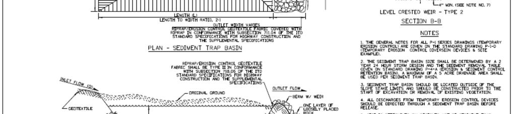
Sediment Trap. A temporary runoff containment area, which promotes sedimentation prior to discharge of the runoff through a stabilized spillway.
 Sediment Trap SC-15 Source: Caltrans Construction Site Best Management Practices Manual, 2003. Description A temporary runoff containment area, which promotes sedimentation prior to discharge of the runoff
Sediment Control Practices. John Mathews Ohio Dept. of Natural Resources, Division of Soil and Water Resources
 Sediment Control Practices John Mathews Ohio Dept. of Natural Resources, Division of Soil and Water Resources Practices Treat the Largest Soil Particles Sand Sand Silt Clay Treated Untreated Settleable
TPDES: Soil, Erosion and Sedimentation Methods
 SAWS TPDES: Soil, Erosion and Sedimentation Methods Philip Handley Supervisor-Resource Protection & Compliance August 25, 2014 TPDES: Soil, Erosion and Sedimentation Methods Soil Common term: Dirt Common
Stone Outlet Sediment Trap
 3.12 Sediment Control Description: A stone outlet sediment trap is a small detention area formed by placing a stone embankment with an integral stone filter outlet across a drainage swale for the purpose
Culvert and Pipe Phasing
 Culvert and Pipe Phasing Barney Blackburn, PE, CPESC, CPSWQ NCDOT Roadside Environmental Unit Soil & Water Engineering Section Supervisor NCDOT Culvert Phasing Process Hydraulics Unit: Culvert Survey Report
Continuing Education Associated with Maintaining CPESC and CESSWI Certification
 Continuing Education Associated with Maintaining CPESC and CESSWI Certification Module 2: Stormwater Management Principles for Earth Disturbing Activities Sponsors: ODOTs Local Technical Assistance Program
Standards for Soil Erosion and Sediment Control in New Jersey May 2012
 STANDARD FOR SEDIMENT BASIN Definition A barrier, dam, excavated pit, or dugout constructed across a waterway or at other suitable locations to intercept and retain sediment. Basins created by construction
Materials. Use materials meeting the following.
 208.01 Section 208. SOIL EROSION AND SEDIMENTATION CONTROL 208.01 Description. Install and maintain erosion and sedimentation controls to minimize soil erosion and to control sedimentation from affecting
FOR PROJECTS INITIATED AFTER NOVEMBER 1, 2008 ITEM 716 EMBANKMENT EARTH OUTLET SEDIMENT TRAP
 AFTER NOVEMBER 1, 2008 ITEM 716 EMBANKMENT EARTH OUTLET SEDIMENT TRAP 716.1 Description. This work shall consist of furnishing, installing, maintaining, and removing temporary erosion protection and sediment
B805 TEMPORARY EROSION AND SEDIMENT CONTROL MEASURES - OPSS 805
 B805 MEASURES - OPSS 805 805.1 GENERAL Construction activities frequently remove protective cover and expose soil to accelerated rates of erosion. Sediments generated thereby can be conveyed via runoff
**Temporary Erosion Control**
 Construction operations And methods **Temporary Erosion Control** The test will more than likely just have a basic word problem dealing with Erosion control, if it has anything on the test. So just review,
INFLOW DESIGN FLOOD CONTROL SYSTEM PLAN 40 C.F.R. PART PLANT YATES ASH POND 2 (AP-2) GEORGIA POWER COMPANY
 GEORGIA POWER COMPANY") INFLOW DESIGN FLOOD CONTROL SYSTEM PLAN 40 C.F.R. PART 257.82 PLANT YATES ASH POND 2 (AP-2) GEORGIA POWER COMPANY EPA s Disposal of Coal Combustion Residuals from Electric Utilities Final Rule (40 C.F.R.
INFLOW DESIGN FLOOD CONTROL SYSTEM PLAN 40 C.F.R. PART 257.82 PLANT YATES ASH POND 2 (AP-2) GEORGIA POWER COMPANY EPA s Disposal of Coal Combustion Residuals from Electric Utilities Final Rule (40 C.F.R.
Sediment Trap. At multiple locations within the project site where sediment control is needed.
 Sediment Trap SE-3 Objectives EC Erosion Control SE Sediment Control TR Tracking Control WE Wind Erosion Control Non-Stormwater NS Management Control Waste Management and WM Materials Pollution Control
Suitable Applications Sediment traps should be considered for use:
 Categories EC Erosion Control SE Sediment Control TC Tracking Control WE Wind Erosion Control Non-Stormwater NS Management Control Waste Management and WM Materials Pollution Control Legend: Primary Objective
STREUVER FIDELCO CAPPELLI, LLC YONKERS DOWNTOWN DEVELOPMENT PHASE 1. DRAFT ENVIRONMENTAL IMPACT STATEMENT For: PALISADES POINT
 STREUVER FIDELCO CAPPELLI, LLC YONKERS DOWNTOWN DEVELOPMENT PHASE 1 DRAFT ENVIRONMENTAL IMPACT STATEMENT For: PALISADES POINT Prepared by: PAULUS, SOKOLOWSKI & SARTOR STORMWATER MANAGEMENT 1. Methodology
APPENDIX B DESIGN CRITERIA FOR TEMPORARY WATER QUALITY BMPS USED DURING CONSTRUCTION
 APPENDIX B DESIGN CRITERIA FOR TEMPORARY WATER QUALITY BMPS USED DURING CONSTRUCTION This Appendix presents design criteria and example calculations for the following temporary water quality BMPs for use
Rock & Aggregate Drop Inlet Protection
 Rock & Aggregate Drop Inlet Protection SEDIMENT CONTROL TECHNIQUE Type 1 System Sheet Flow Sandy Soils Type 2 System [1] Concentrated Flow Clayey Soils Type 3 System Supplementary Trap Dispersive Soils
Stormwater Guidelines and Case Studies. CAHILL ASSOCIATES Environmental Consultants West Chester, PA (610)
") Stormwater Guidelines and Case Studies CAHILL ASSOCIATES Environmental Consultants West Chester, PA (610) 696-4150 www.thcahill.com Goals and Challenges for Manual State Stormwater Policy More Widespread
Stormwater Guidelines and Case Studies CAHILL ASSOCIATES Environmental Consultants West Chester, PA (610) 696-4150 www.thcahill.com Goals and Challenges for Manual State Stormwater Policy More Widespread
APPENDIX G APPENDIX G SEDIMENT CONTAINMENT SYSTEM DESIGN RATIONALE
 APPENDIX G SEDIMENT CONTAINMENT SYSTEM DESIGN RATIONALE March 18, 2003 This page left blank intentionally. March 18, 2003 G-2 FIGURES Page # Figure G.1 Estimated Runoff from Precipitation Over Different
Agenda. INDOT Office of Environmental Services. Describe Results of FHWA QAR. Landscape and Waterway Permitting Unit. Interviews Site Inspections
 Nathan Saxe Administrator, Ecology and Waterway Permitting Section Back to Basics: Erosion and Sediment Control FHWA INDOT Quality Assurance Review (QAR) Results 1 Agenda INDOT Office of Environmental
Sediment and Erosion Control Techniques on Stream Restoration Projects
 Sediment and Erosion Control Techniques on Stream Restoration Projects D. R. Clinton, G. D. Jennings, R. A. McLaughlin, D. A. Bidelspach 1 ABSTRACT Erosion control, sediment loss and turbidity control
Coarse Sediment Traps
 Coarse Sediment Traps SEDIMENT CONTROL TECHNIQUE Type 1 System Sheet Flow Sandy Soils Type 2 System [1] Concentrated Flow Clayey Soils [2] Type 3 System Supplementary Trap Dispersive Soils [1] Though primarily
U-Shaped Sediment Traps
 U-Shaped Sediment Traps SEDIMENT CONTROL TECHNIQUE Type 1 System Sheet Flow Sandy Soils Type 2 System Concentrated Flow Clayey Soils [1] Type 3 System Supplementary Trap Dispersive Soils [1] Generally
[1] Performance of the sediment trap depends on the type of outlet structure and the settling pond surface area.
![[1] Performance of the sediment trap depends on the type of outlet structure and the settling pond surface area.](/thumbs/76/74245181.jpg "[1] Performance of the sediment trap depends on the type of outlet structure and the settling pond surface area.") Sediment Trench SEDIMENT CONTROL TECHNIQUE Type 1 System Sheet Flow Sandy Soils Type 2 System [1] Concentrated Flow Clayey Soils Type 3 System [1] Supplementary Trap Dispersive Soils [1] Performance of
Sediment Trench SEDIMENT CONTROL TECHNIQUE Type 1 System Sheet Flow Sandy Soils Type 2 System [1] Concentrated Flow Clayey Soils Type 3 System [1] Supplementary Trap Dispersive Soils [1] Performance of
NORTH DAKOTA DEPARTMENT OF TRANSPORTATION SPECIAL PROVISION TEMPORARY EROSION AND SEDIMENT BEST MANAGEMENT PRACTICES
 Page 1 of 5 NORTH DAKOTA DEPARTMENT OF TRANSPORTATION SPECIAL PROVISION TEMPORARY EROSION AND SEDIMENT BEST MANAGEMENT PRACTICES 1. GENERAL Install, maintain and remove appropriate Temporary Best Management
Instream Sediment Control Systems
 Instream Sediment Control Systems INSTREAM PRACTICES Photo 1 Photo 2 Modular sediment The information contained within this series of fact sheets deals only with the design of temporary instream sediment
Selected Site BMPs: Why s the Water Muddy? John C. Hayes, Ph.D., P. E. Biosystems Engineering Clemson University
 Selected Site BMPs: Why s the Water Muddy? John C. Hayes, Ph.D., P. E. Biosystems Engineering Clemson University The BMP worked fine until last week when it rained! Turbidity Best Management Practices
APPENDIX B WORKSHEETS & EXHIBITS
 APPENDIX B WORKSHEETS & EXHIBITS A worksheet provides the designer a representation of a measure that allows for input of specific design criteria. The plan designer will be required to assess field conditions
WQ Outlet Design Single Orifice Orifice diameter = 24. Perforated riser/orifice Plate Outlet area per perforation row = 4
 These calculations should be used when designing the outlet structures for extended wet and dry detention basins (Sections 4. 7 and 4.8). The water quality outlet size and the trash rack design will vary
HISTORY OF CONSTRUCTION FOR EXISTING CCR SURFACE IMPOUNDMENT PLANT GASTON ASH POND 40 CFR (c)(1)(i) (xii)
(1)(i) (xii)") HISTORY OF CONSTRUCTION FOR EXISTING CCR SURFACE IMPOUNDMENT PLANT GASTON ASH POND 40 CFR 257.73(c)(1)(i) (xii) (i) Site Name and Ownership Information: Site Name: E.C. Gaston Steam Plant Site Location:
HISTORY OF CONSTRUCTION FOR EXISTING CCR SURFACE IMPOUNDMENT PLANT GASTON ASH POND 40 CFR 257.73(c)(1)(i) (xii) (i) Site Name and Ownership Information: Site Name: E.C. Gaston Steam Plant Site Location:
APPENDIX A: EROSION & SEDIMENT CONTROL FORMS
 APPENDIX A: EROSION & SEDIMENT CONTROL FORMS Croy Engineering # 1580.08 EROSION & SEDIMENT CONTROL FORMS Appendix-1 This page intentionally left blank. Croy Engineering # 1580.08 EROSION & SEDIMENT CONTROL
SILT FENCE EFFECTIVENESS
 SILT FENCE EFFECTIVENESS Michelle G. Holloway, Department of Earth Sciences, University of South Alabama, Mobile, AL 36688. E-mail: MLG@jaguar1.usouthal.edu. Sediment is the number one pollutant in Dog
EROSION CONTROL NARRATIVE
 EROSION CONTROL NARRATIVE Erosion and sediment control has been designed for the Willow Bend Phase I Subdivision according to UDFCD and the City of Thornton criteria, in order to minimize erosion and sediment
The Mechanics Of Sediment Basin Operation
 March 2017 Technical Explanatory Note on Sediment Basin Design prepared by Grant Witheridge Catchments & Creeks Pty Ltd ABN 34 078 164 119 The Mechanics Of Sediment Basin Operation 1. Introduction This
Woodford County Erosion Prevention Plan and Permit. Application #
 Woodford County Erosion Prevention Plan and Permit Application # Date Instructions: Applicant will complete Parts A and B, and attach a proposed site diagram. This diagram must be completed in accordance
MIDDLESEX COUNTY Department of Planning and Community Development P.O. Box 427, Saluda, VA Phone: Fax:
 MIDDLESEX COUNTY Department of Planning and Community Development P.O. Box 427, Saluda, VA 23149 Phone: 804-758-3382 Fax: 804-758-0061 LAND DISTURBANCE PERMIT SUBMISSION REQUIREMENTS In order to expedite
Sediment Control Log (SCL)
") Description A sediment control log is a linear roll made of natural materials such as straw, coconut fiber, or other fibrous material trenched into the ground and held with a wooden stake. Sediment control
Description A sediment control log is a linear roll made of natural materials such as straw, coconut fiber, or other fibrous material trenched into the ground and held with a wooden stake. Sediment control
Section 4: Model Development and Application
 Section 4: Model Development and Application The hydrologic model for the Wissahickon Act 167 study was built using GIS layers of land use, hydrologic soil groups, terrain and orthophotography. Within
Specifications Whitcomb Elementary School Demolition January 15, 2016
 SECTION 31 2500 - EROSION CONTROL PART 1 - GENERAL 1.1 RELATED DOCUMENTS: A. The provisions of the Contract Documents apply to the work of this Section. B. The Virginia Erosion and Sediment Control Handbook,
Guide to the use of the Erosion and Sediment Control Evaluation Tool
 Guide to the use of the Erosion and Sediment Control Evaluation Tool December 2017 If you require content in an alternate format please contact us at 905-895-1281 or by email at Accessibility@LSRCA.on.ca
BRANDON LAKES AVENUE PRE AND POST CONDITIONS DRAINAGE REPORT
 BRANDON LAKES AVENUE PRE AND POST CONDITIONS DRAINAGE REPORT Hillsborough County Public Works County Center, 22nd Floor 601 E. Kennedy Blvd. Tampa, FL 33602 BRANDON LAKES AVENUE DRAINAGE IMPROVEMENTS Capital
ADDENDA #1 CONTRACT # C May 3, 2013 Page 1 of 1
 State of California Natural Resources Agency Edmund G. Brown Jr., Governor DEPARTMENT OF PARKS AND RECREATION Major General Anthony L. Jackson, USMC (Ret), Director ADDENDA #1 CONTRACT # C1247040 May 3,
Chapter 7 Mudflow Analysis
 Chapter 7 Mudflow Analysis 7.0 Introduction This chapter provides information on the potential and magnitude of mud floods and mudflows that may develop in Aspen due to rainfall events, snowmelt, or rain
STORMWATER REPORT FRITO LAY SUBDIVISION NO. 3
 STORMWATER REPORT FRITO LAY SUBDIVISION NO. 3 May 2018 STORMWATER REPORT I. Subdivision Data a. The parcel is adjacent to the existing Frito Lay property in Topeka; and the subject plat application encompasses
ARTICLE 5 (PART 2) DETENTION VOLUME EXAMPLE PROBLEMS
 DETENTION VOLUME EXAMPLE PROBLEMS") ARTICLE 5 (PART 2) DETENTION VOLUME EXAMPLE PROBLEMS Example 5.7 Simple (Detention Nomograph) Example 5.8 Offsite and Unrestricted Areas (HEC-HMS) Example 5.9 Ponds in Series w/ Tailwater (HEC-HMS) Example
ARTICLE 5 (PART 2) DETENTION VOLUME EXAMPLE PROBLEMS Example 5.7 Simple (Detention Nomograph) Example 5.8 Offsite and Unrestricted Areas (HEC-HMS) Example 5.9 Ponds in Series w/ Tailwater (HEC-HMS) Example
Appendix E Guidance for Shallow Flooding Analyses and Mapping
 Appendix E Guidance for Shallow Flooding Analyses and Mapping E.1 Introduction Different types of shallow flooding commonly occur throughout the United States. Types of flows that result in shallow flooding
Template for Sediment and Erosion Control Plan General Instructions. Section Instructions
 Template for Sediment and Erosion Control Plan General Instructions Introduction: Soil erosion and sediment deposition from farmlands can contribute to degraded surface water quality. Sediment delivery
CCR Rule Annual Inspection Report (cont.) 2
 2") The inspection findings consisted of maintenance items and items that were not observed to be signs or potential signs of significant structural weakness. No deficiencies or disrupting conditions that
The inspection findings consisted of maintenance items and items that were not observed to be signs or potential signs of significant structural weakness. No deficiencies or disrupting conditions that
Large-Scale Sediment Retention Device Testing (ASTM D 7351) SedCatch Sediment Basket Inlet Filter Exposed to 6% Sediment Load
 SedCatch Sediment Basket Inlet Filter Exposed to 6% Sediment Load") Large-Scale Sediment Retention Device Testing (ASTM D 7351) of SedCatch Sediment Basket Inlet Filter Exposed to 6% Sediment Load February 2010 Submitted to: SedCatch Environmental Products 8380 Point O
Large-Scale Sediment Retention Device Testing (ASTM D 7351) of SedCatch Sediment Basket Inlet Filter Exposed to 6% Sediment Load February 2010 Submitted to: SedCatch Environmental Products 8380 Point O
Construction Exits Rock pads
 Construction Exits Rock pads SEDIMENT CONTROL TECHNIQUE Type 1 System Sheet Flow Sandy Soils Type 2 System Concentrated Flow [1] Clayey Soils Type 3 System Supplementary Trap Dispersive Soils [1] Minor
Stormwater Outlet Sediment Traps
 Stormwater Outlet Traps SEDIMENT CONTROL TECHNIQUES Photo 1 Excavated sediment trap just prior to scheduled clean-out (note energy dissipater at end of pipe) Photo 2 A supplementary straw bale barrier
Large-Scale Sediment Retention Device Testing (ASTM D 7351) SedCatch Sediment Basket Inlet Filter Exposed to 1.5% Sediment Load
 SedCatch Sediment Basket Inlet Filter Exposed to 1.5% Sediment Load") Large-Scale Sediment Retention Device Testing (ASTM D 7351) of SedCatch Sediment Basket Inlet Filter Exposed to 1.5% Sediment Load February 2010 Submitted to: SedCatch Environmental Products 8380 Point
Large-Scale Sediment Retention Device Testing (ASTM D 7351) of SedCatch Sediment Basket Inlet Filter Exposed to 1.5% Sediment Load February 2010 Submitted to: SedCatch Environmental Products 8380 Point
City of Columbia BMP Manual. Detailed Unified Sizing Criteria Example Wet Pond Design
 City of Columbia BMP Manual Detailed Unified Sizing Criteria Example Wet Pond Design April 17, 2013 Wet Pond Example: Unified Sizing Criteria Methodology Base Data Location: Rome, GA Site Drainage Area
Type 1 System Sheet Flow Sandy Soils Type 2 System Concentrated Flow Clayey Soils Type 3 System [1] Supplementary Trap Dispersive Soils
![Type 1 System Sheet Flow Sandy Soils Type 2 System Concentrated Flow Clayey Soils Type 3 System [1] Supplementary Trap Dispersive Soils](/thumbs/77/76519623.jpg "Type 1 System Sheet Flow Sandy Soils Type 2 System Concentrated Flow Clayey Soils Type 3 System [1] Supplementary Trap Dispersive Soils") Sediment Weirs SEDIMENT CONTROL TECHNIQUE Type 1 System Sheet Flow Sandy Soils Type 2 System Concentrated Flow Clayey Soils Type 3 System [1] Supplementary Trap Dispersive Soils [1] Type 3 classification
Sediment Weirs SEDIMENT CONTROL TECHNIQUE Type 1 System Sheet Flow Sandy Soils Type 2 System Concentrated Flow Clayey Soils Type 3 System [1] Supplementary Trap Dispersive Soils [1] Type 3 classification
Sediment Capture in Pervious Concrete Pavement tsystems: Effects on Hydrological Performance and Suspended Solids
 Concrete Sustainability Conference April 14 th 2010, Tempe, AZ Sediment Capture in Pervious Concrete Pavement tsystems: Effects on Hydrological l Performance and Suspended Solids Discharge Luis A. Mata,
Stormwater Inlet Sediment Traps
 Stormwater Inlet Sediment Traps SEDIMENT CONTROL TECHNIQUES Photo 1 Kerb inlet Photo 2 Field (drop) inlet Table 1 provides the recommended default classification of various sediment control systems suitable
Black Gore Creek 2013 Sediment Source Monitoring and TMDL Sediment Budget
 Black Gore Creek 2013 Sediment Source Monitoring and TMDL Sediment Budget Prepared for: Prepared By: - I. Introduction The Black Gore Creek Total Maximum Daily Load (TMDL) was developed in collaboration
WELCOME Lake Wabukayne OPEN HOUSE
 WELCOME Lake Wabukayne Sediment Removal Project OPEN HOUSE We are here to: Update you, the community, on recent developments and activities at Lake Wabukayne Present the preferred alternative and receive
Special Public Notice
 Special Public Notice Applicability: General Public Date: June 3, 2014 The purpose of this public notice is to inform you of existing guidance and policy contained in Regulatory Guidance Letter 05-04 concerning
WATER MANAGEMENT REPORT FOR PAGE ESTATES
 WATER MANAGEMENT REPORT FOR PAGE ESTATES SLB Consulting of SW Florida, LLC PO Box 2826 Bonita Springs, FL. 34133 Phone: 239-948-9566 sandra@slbconsult.com C.O.A. # 25395 September 1, 2014 Sandra L. Bottcher
CONSTRUCTION EXIT SEDIMENT BARRIER
 241428_itizen ield Guide_v3 2/22/06 11:09 M Page 1 (1,1) ONSTRUTION EXIT stone pad located where traffic leaves a construction site to eliminate the transport of soil to public streets. SEDIMENT BRRIER
Roger Andy Gaines, Research Civil Engineer, PhD, P.E.
 Roger Andy Gaines, Research Civil Engineer, PhD, P.E. Research Civil Engineer/Regional Technical Specialist Memphis District August 24, 2010 Objectives Where we have been (recap of situation and what s
Provide sediment tubes for ditch check and Type A inlet structure filter applications that meet the minimum performance requirements of Table 1.
 Supplemental Technical Specification for SEDIMENT TUBES SCDOT Designation: SC-M-815-1 (03/08) 1.0 Sediment Tubes This Supplemental Specification replaces sections 815.1.1.2, 815.2.3, 815.4.5, 815.5, and
Limited Visual Dam Safety Inspections OA Oahu Reservoir No Oahu, Hawaii
 Limited Visual Dam Safety Inspections OA00137 Oahu Reservoir No. 155 Oahu, Hawaii Prepared by: U.S. ARMY CORPS OF ENGINEERS HONOLULU DISTRICT STATE OF HAWAII DEPARTMENT OF LAND AND NATURAL RESOURCES May
STORMWATER MANAGEMENT REPORT
 STORMWATER MANAGEMENT REPORT THE FAIRWAYS AT EDGEWOOD LOTS 5 & 6, BLOCK 1201 TOWNSHIP OF RIVER VALE BERGEN COUNTY, NEW JERSEY PREPARED BY: DAPHNE A. GALVIN PROFESSIONAL ENGINEER LICENSE NO. 24GE03434900
Orica Australia Pty Ltd Ammonium Nitrate Facility Upgrade
 Orica Australia Pty Ltd Ammonium Nitrate Facility Upgrade January 2010 Revision 0 Contents 1. Introduction 1 1.1 Purpose 1 1.2 Objectives 1 1.3 Relevant Environmental Legislation, Guidelines and Policies
UGRC 144 Science and Technology in Our Lives/Geohazards
 UGRC 144 Science and Technology in Our Lives/Geohazards Flood and Flood Hazards Dr. Patrick Asamoah Sakyi Department of Earth Science, UG, Legon College of Education School of Continuing and Distance Education
Annual Performance Report: State Assessment Data
 Annual Performance Report: 2005-2006 State Assessment Data Summary Prepared by: Martha Thurlow, Jason Altman, Damien Cormier, and Ross Moen National Center on Educational Outcomes (NCEO) April, 2008 The
What Is Water Erosion? Aren t they the same thing? What Is Sediment? What Is Sedimentation? How can Sediment Yields be Minimized?
 Jerald S. Fifield, Ph.D. CISEC HydroDynamics Incorporated Parker, CO 303-841-0377 Aren t they the same thing? What Is Sediment? Soil particles deposited or suspended in water or air The process of depositing
Chapter 7 Mudflow Analysis
 Chapter 7 Mudflow Analysis 7.0 Introduction This chapter provides information on the potential and magnitude of mud floods and mudflows that may develop in Aspen due to rainfall events, snowmelt, or rain
THE NEED FOR AN ADDITIONAL SPILLWAY AT THE SANFORD DAM BOILING SPRING LAKES, NC. Presentation for The Brunswick County Commissioners April 20, 2015
 THE NEED FOR AN ADDITIONAL SPILLWAY AT THE SANFORD DAM BOILING SPRING LAKES, NC Presentation for The Brunswick County Commissioners April 20, 2015 The Sanford Dam Earth Dam constructed in 1961 Drainage
MAPPING THE RAINFALL EVENT FOR STORMWATER QUALITY CONTROL
 Report No. K-TRAN: KU-03-1 FINAL REPORT MAPPING THE RAINFALL EVENT FOR STORMWATER QUALITY CONTROL C. Bryan Young The University of Kansas Lawrence, Kansas JULY 2006 K-TRAN A COOPERATIVE TRANSPORTATION
STRUCTURAL STABILITY ASSESSMENT
 STRUCTURAL STABILITY ASSESSMENT CFR 257.73(d) Bottom Ash Pond Complex Cardinal Plant Brilliant, Ohio October, 2016 Prepared for: Cardinal Operating Company Cardinal Plant Brilliant, Ohio Prepared by: Geotechnical
Rock Sizing for Batter Chutes
 Rock Sizing for Batter Chutes STORMWATER MANAGEMENT PRACTICES Photo 1 Rock-lined batter chute Photo 2 Rock-lined batter chute 1. Introduction In the stormwater industry a chute is a steep drainage channel,
 DRAFT DRAFT DRAFT DRAFT DRAFT SEDIMENT CONTROLS Method Application Description BMP Sediment fencing Flat Ground Y Anywhere low flow runoff is Sloping Ground Y Geotextile fabric, buried at the bottom
Weighting of Field Monitoring Data With Probability Distributions of Daily Rainfall
 Weighting of Field Monitoring Data With Probability Distributions of Daily Rainfall Abstract James H. Lenhart, PE, D.WRE and Scott A. de Ridder CONTECH Stormwater Solutions, 11835 NE Glenn Widing Drive,
Little Swan Lake. Dam Inspection & Siltation Study Prepared By: William Klingner, P.E., CFM October 28, 2018
 Little Swan Lake Dam Inspection & Siltation Study Prepared By: William Klingner, P.E., CFM October 28, 2018 Agenda Little Swan Lake Dam Inspection Theoretical Little Swan Lake Siltation Rate Calculations
Chutes Part 5: Rock linings
 Chutes Part 5: Rock linings DRAINAGE CONTROL TECHNIQUE Low Gradient Velocity Control Short-Term Steep Gradient Channel Lining Medium-Long Term Outlet Control [1] Soil Treatment Permanent [2] [1] Chutes
September 6, City of Thornton 9500 Civic Center Drive Thornton, CO (303) RE: Maverik Thornton, CO - Drainage Report
 RE: Maverik Thornton, CO - Drainage Report") September 6, 2016 City of Thornton 9500 Civic Center Drive Thornton, CO 80229 (303) 538-7295 RE: Maverik Thornton, CO - Drainage Report As per your request, we are submitting to you the drainage report
September 6, 2016 City of Thornton 9500 Civic Center Drive Thornton, CO 80229 (303) 538-7295 RE: Maverik Thornton, CO - Drainage Report As per your request, we are submitting to you the drainage report
Introduction and Organization of Instructions The following is a brief outline for use the skimmer, how to size and shape the basin, how to construct
 A Manual for Designing, Installing, and Maintaining Skimmer Sediment Basins J. W. Faircloth & Son Post Office Box 757 Hillsborough, North Carolina 27278 Telephone/Fax (919) 732-1266 From fairclothskimmer.com,
Coal Combustion Residuals Unit Inflow Design Flood Control System Plan
 Coal Combustion Residuals Unit Inflow Design Flood Control System Plan Virginia Electric and Power Company Chesterfield Power Station Upper (East) Pond Chesterfield County, Virginia GAI Project Number:
Low Gradient Velocity Control Short Term Steep Gradient Channel Lining Medium-Long Term Outlet Control Soil Treatment Permanent [1]
![Low Gradient Velocity Control Short Term Steep Gradient Channel Lining Medium-Long Term Outlet Control Soil Treatment Permanent [1]](/thumbs/87/96478185.jpg "Low Gradient Velocity Control Short Term Steep Gradient Channel Lining Medium-Long Term Outlet Control Soil Treatment Permanent [1]") Rock Linings DRAINAGE CONTROL TECHNIQUE Low Gradient Velocity Control Short Term Steep Gradient Channel Lining Medium-Long Term Outlet Control Soil Treatment Permanent [1] [1] The design of permanent installations
Rock Linings DRAINAGE CONTROL TECHNIQUE Low Gradient Velocity Control Short Term Steep Gradient Channel Lining Medium-Long Term Outlet Control Soil Treatment Permanent [1] [1] The design of permanent installations
design, construction, operation, and maintenance of the BAP is consistent with recognized and generally accepted good engineering standards.
 design, construction, operation, and maintenance of the BAP is consistent with recognized and generally accepted good engineering standards. In addition to the field inspection, Associated Engineers, Inc.
 Red River Flooding June 2015 Caddo and Bossier Parishes Presented by: Flood Technical Committee Where the Rain Falls Matters I-30 versus I-20 I-20 Backwater and Tributary Floods (Localized) 2016 Flood
HOTEL KANATA 160 HEARST WAY KANATA, ONTARIO SERVICING REPORT. Prepared for: David Johnston Architect. Prepared By:
 HOTEL KANATA 160 HEARST WAY KANATA, ONTARIO SERVICING REPORT Prepared for: David Johnston Architect Prepared By: BaseTech Consulting Inc. 309 Roywood Crescent Newmarket, Ontario L3Y 1A6 BCI Project No.
North Carolina Department of Environment and Natural Resources Division Energy, Mineral, and Land Resources Land Quality Section
 Tracy E. Davis, PE, CPM Director City of Greenville Attention: Scott Godefroy 1500 Beatty Street Greenville, NC 27834 North Carolina Department of Environment and Natural Resources Division Energy, Mineral,
Template for Sediment and Erosion Control Plan General Instructions
 Template for Sediment and Erosion Control Plan General Instructions Introduction: Soil erosion and sediment deposition from farmlands can contribute to degraded surface water quality. Sediment delivery
APPENDIX E GREATER SPRINGFIELD RELIABILTIY PROJECT DRAINAGE ANALYSIS FOR THE NEWGATE/PHELPS ROAD AND THE HATCHETT HILL ROAD AREAS
 APPENDIX E GREATER SPRINGFIELD RELIABILTIY PROJECT DRAINAGE ANALYSIS FOR THE NEWGATE/PHELPS ROAD AND THE HATCHETT HILL ROAD AREAS New England East-West Solution (NEEWS) Greater Springfield Reliability
M. Sloat, AAg., CPESC R.J. Redden, R.P.Bio., A.Sc.T., CPESC. EDI Environmental Dynamics Inc Continental Way Prince George, B.C.
 OVERVIEW OF BEST PRACTICES FOR SURFACE EROSION PROTECTION AND SEDIMENT CONTROL FOR THE DEVELOPMENT PHASE OF SURFACE MINING FOR COAL IN NORTHEAST BRITISH COLUMBIA M. Sloat, AAg., CPESC R.J. Redden, R.P.Bio.,
Erosion and Sediment Control Measures 2.7 Silt Fences
 Erosion and Sediment Control Measures Silt fences are designed to intercept sheet flow sediment laden stormwater run-off and filter out both the larger and smaller particles of sediment. Silt fences and
APPENDIX B HYDROLOGY
 APPENDIX B HYDROLOGY TABLE OF CONTENTS 1.0 INTRODUCTION... 1 2.0 PROBABLE MAXIMUM PRECIPITATION (PMP)... 1 3.0 DESIGN FLOW CALCULATION... 1 4.0 DIVERSION CHANNEL SIZING... 2 5.0 REFERENCES... 4 LIST OF
Storm Sewer Design [2]
![Storm Sewer Design [2]](/thumbs/82/86956590.jpg "Storm Sewer Design [2]") Class 5 [1] Storm Sewer Design 9. Check Q < Qf and Vmax > vf > Vmin. Vmin is normally specified to avoid sedimentation. This will normally be 1.0 m/s at pipe full condition. (BS EN 752 suggests that for
Class 5 [1] Storm Sewer Design 9. Check Q < Qf and Vmax > vf > Vmin. Vmin is normally specified to avoid sedimentation. This will normally be 1.0 m/s at pipe full condition. (BS EN 752 suggests that for
LOCATED IN INDIAN RIVER COUNTY PREPARED FOR S.J.R.W.M.D. AND F.W.C.D. DECEMBER, 2003 Updated 2007 Updated May 2014 PREPARED BY
 FELLSMERE WATER CONTROL DISTRICT EAST MASTER DRAINAGE PLAN AND STORMWATER HYDROLOGIC ANALYSIS OF THE GRAVITY DRAINAGE SYSTEM LOCATED BETWEEN THE EAST BOUNDARY, LATERAL U, THE MAIN CANAL, AND DITCH 24 LOCATED
Stage Discharge Tabulation for Only Orifice Flow
 Stage Discharge Tabulation for Only Orifice Flow DEPTH STAGE DISCHARGE (meters) (feet) (meters) (feet) (m 3 /s) (ft 3 /s) 0 0.20 0.40 0.60 0.80 1.00 1.20 1.40 1.60 1.80 2.00 0.7 1.3 2.0 2.6 3.3 3.9 4.6
Chapter Introduction EROSION AND SEDIMENT CONTROL. Erosion
 Chapter 8. EROSION AND SEDIMENT CONTROL 8.1. Introduction Natural erosion has been occurring since the earth was formed. This process, which generally occurs at a relatively slow rate, has shaped and molded
Wellsgate Terrace SPECIFICATIONS.
 GRADING NOTES: 1. LOT GRADING SHALL BE COMPLETED TO PROVE SUFFICIENT DIRT ON EACH PAD TO ACHIEVE THE CRITICAL PAD GRADES AND SPOT GRADES ON EACH LOT. AFTER ACHIEVING CRITICAL PAD GRADES INDICATED ON THIS
Construction Exits Vibration grids
 Construction Exits Vibration grids SEDIMENT CONTROL TECHNIQUE Type 1 System Sheet Flow Sandy Soils Type 2 System Concentrated Flow Clayey Soils [1] Type 3 System Supplementary Trap Dispersive Soils [1]
Rock Sizing for Multi-Pipe & Culvert Outlets
 Rock Sizing for Multi-Pipe & Culvert Outlets STORMWATER AND WATERWAY MANAGEMENT PRACTICES Photo 1 Rock pad outlet structure at end of a duel stormwater pipe outlet Photo 2 Rock pad outlet structure at
Nursing Facilities' Life Safety Standard Survey Results Quarterly Reference Tables
 Nursing Facilities' Life Safety Standard Survey Results Quarterly Reference Tables Table of Contents Table 1: Summary of Life Safety Survey Results by State Table 2: Ten Most Frequently Cited Life Safety
Modeling Great Britain s Flood Defenses. Flood Defense in Great Britain. By Dr. Yizhong Qu
 Modeling Great Britain s Flood Defenses AIRCurrents Editor s note: AIR launched its Inland Flood Model for Great Britain in December 2008. The hazard module captures the physical processes of rainfall-runoff