MONITORING SYSTEM GEOPHYSICAL ASPECTS OF CAPPING OPERATIONS
|
|
|
- Anastasia Boyd
- 5 years ago
- Views:
Transcription
1 STATUS REPORT DISPOSAL OPERATIONS AT THE CENTRAL LONG ISLAND SOUND DISPOSAL SITE DISPOSAL AREA MONITORING SYSTEM (DAMOS) FIELD VERIFICATION PROGRAM () GEOPHYSICAL ASPECTS OF CAPPING OPERATIONS CONTRIBUTION 25 MAY 1983 US Army Corps of Engineers New England Division
2 .----SCIENCE APPLICATIONS, INC , STATUS REPORT DISPOSAL OPERATIONS AT THE CENTRAL LONG ISLAND SOUND DISPOSAL SITE 20 MAY 1983 CONTRIBUTION #25 Contract #DACW33-83-D-0004 SUbmitted to: Richard C. Semonian U.S. Army Engineer Division, New England Operations Division 424 Trapelo Road waltham, MA Submitted by: Robert W. Morton Science Applica ions, Inc. Ocean Science & Technology Division 379 Thames Street Newport, RI (401) ~ ~
3 .---SCIENCE APPLICATIONS, INC , TN3LE OF CONTENTS 1. INTRODUCTION 1 2. MILL & QUINNIPIAC RIVER DISPOSAL SITE (MQRDS) 4 3. CAP SITE U CAP SITE # ~ ~ i
4 ,...---SCIENCE APPLICATIDNS. INC , LIST OF FIGURES 1-1 survey Grids CLIS Disposal Site 2-1 MQRDS - Pre-Disposal - March, MQRDS - Post - MQR - Disposal - June, MQRDS - Pre-New Haven Disposal - December, MQRDS - Distribution of Disposal Points 2-5 MQRDS Interim Disposal survey - May, Cap Site #1 Pre-Disposal - April, cap Site #1 Side Scan of Ambient Bottom 3-3 Cap Site #1 Side Scan of High Reflectance Bottom 3-4 cap Site #1 Side Scan of Dredged Material 3-5 Cap Site #1 Post-Black Rock Disposal - April, cap Site #2 Pre-Disposal - April, Cap Site #2 Pre-Capping - April, Pre-Disposal - December, Side Scan Record Pre-Disposal 5-3 1st Interim Survey - April, nd Interim Survey - May, Side Scan Dredged Material Signature 5-6 Side Scan Dredged Material Signature 5-7 Side Scan Scow Leakage Track 5-8 Post-Disposal - May, Vertical Profiles L ;/9.. ii
5 ,..---SCIENCE APPLICATIONS. INC , LIST OF TABLES 1-1 Summary of Field Observations Obtained at the ells Disposal Site ~ ~ iii
6 1. INTRODUCTION During the spring of 1983, a series of dredging and disposal operations have occurred utilizing the Central Long Island Sound Disposal Site. A major effort has been made under the DAMOS program to monitor these disposal operations at four different locations within the CLIS site. These locations and associated operations are defined as follows: MQR Site - Disposal of approximately 1 million m 3 of sediment from New Haven Harbor dumped using a Loran-C navigation control system Cap Site 1 - Disposal of approximately m 3 of sediment from Black Rock Harbor to be capped by silt from New Haven Cap Site 2 - Disposal of approximately m 3 of sediment from Black Rock Harbor to be capped by sand from the outer channel of New Haven Site - Disposal of approximately m 3 of sediment from Black Rock Harbor An overview of the CLIS disposal site showing the relative positions of the disposal points and the extent of survey coverage is presented in Figure 1-1. All of these sites have been studied in detail using replicate precision bathymetric surveys, side scan sonar, precision grab sampling and diver observations as well as additional, more specialized observations in some cases. This report is being compiled to provide a summary of data obtained during the period of disposal in order to assess the effectiveness of the disposal operation. Consequently, all data have not yet been reviewed for accuracy, and in the case of replicate bathymetric surveys, fully corr~cted for tide and sound velocity. However, even though absolute values of depths may not 1
7 CHART SCALE: 1/15000 ~ SURVE) GRIDS CENTRAL LONG ISLAND SOUND CS-2 DISPOS AL SITE STNH-N Nj ~ NORWALK It-::!:~-J C::.:".::='::: -:-:=.-..::--::::-:: t---- -=-.::...::~~:::_-_=~:_=_:: SCALE 1m) Figure 1-1
8 be fully corrected, the relative differences between surveys are valid and comparisons to determine distribution and thickness of dredged material can be made with confidence. A summary of the work conducted at the CLIS Disposal Site during recent months is presented in Table 1-1. The following sections provide a quick look summary of data from each site. Further amplification and interpretation of results will be provided in future reports. After completion of disposal operations in June, additional work at the CLIS site will consist of intensive post disposal monitoring and subsequent periodic cruises to monitor long term effects. 2. MILL & QUINNIPIAC RIVER DISPOSAL SITE (MQR) During the spring of 1982, sediment from the Mill River in New Haven was capped with additional material from the Quinnipiac River. Figures 2-1 and 2-2 present bathymetric charts before and after that operation. The mound created by the capping operation is readily apparent in Figure 2-2 as an elliptical shaped elevation with axes of 300 m and 180 m and a maximum elevation of approximately 1.5 m. Figure 2-3 shows the same site 9 months after disposal and immediately prior to initiation of the present New Haven project. Very little change had occurred over this period indicating a stable containment situation. Initial disposal at the MQR site in 1983 consisted of point dumping a small quantity of sediment from Bridgeport Harbor, which was relatively high in heavy metal and organic content. This material was then capped by the large volume of 4
9 Table 1-1 Summary of Field Observations Obtained at the CLIS Disposal Site Date Site Operation MQR Display Disposal Buoy Initial Baseline Survey Diving & TV Reconnaissance Sediment Grab Samples MQR Baseline Survey MQR Interim Survey Diver Observations Display Daisy MQR Reconnaissance Side Scan Survey Sediment Samples Baseline Survey MQR Sediment Samples Sediment Samples MQR Remove Buoy Post-Disposal Survey Side Scan Survey Sediment Samples Diver Observations Sediment Samples REMOTS Photography REMOTS Photography REMOTS Photography REMOTS Photography MQR CLIS REF Monitoring Survey Biological & Sediment Samples MQR Remove DAISY & Reset Diver Observations 5
10 MQR MQR MQR MQR CSil CSil CSi2 csil CSi2 CS il CSi2 CS#2 Diver Observations EPA Sediment Samples Underwater TV Reset DAISY EPA Biological Samples Sediment Samples Baseline Survey Diving Operations water Sampling Monitoring Survey REMOTS Survey Deploy Mussel Cages (UCONN) Deploy Mussel Cages (EPA) Diver Observations Biological Samples Diver Observations Deploy Disposal Buoy Deploy Disposal Buoy REMOTS Survey Baseline Sediment Survey Baseline REMOTS Survey Deploy CS#l Disposal Buoy Deploy Deflection & Erosion Stakes Baseline REMOTS Survey Baseline Sediment Survey Baseline Bathymetric Survey Baseline Side Scan Survey,Baseline Bathymetric Survey Deploy Diver TRansect Lines Deploy Compaction Stakes Deploy Deflection Stake Remove DAISY Sediment Samples at CLIS-REF Deploy Disposal Buoy Deploy Compaction Stakes Deplot DAISYS (2) 6
11 CSH MQR CS4I2 CSH CS4I2 MQR CSH CS4I2 MQR CS4I2 csh CS#2 Water Column Sampling Retrieve Mussels. (EPA) Retrieve Mussels Sediment Chemistry Samples Sediment Erosion Test Samples Recycle DAISY's Interim Side Scan Survey Post Black Rock Diver Observations Bathymetric Profiles over Mound Density Probe Measurements Post Black Rock Bathymetric Survey Interim Bathymetric Survey Ihterim Bathymetric Survey Sediment Distribution Survey Interim Bathymetric Survey Side Scan Survey Interim Bathymetriq Survey Sediment Distribution Survey Sediment Distribution Survey Sediment Distribution Survey Sediment Distribution Survey Side Scan Survey Diving Observations Diving Observations Diving Observations Post Disposal Diver Observations Post Disposal Baseline Bathymetric Survey Water Column Sampling 7
12 MQRDS PRE-DISPOSAL MARCH 1982 \ <, 1il 204 c!:? O. (J. ~ fy 0 = ~1 OB OB.4 o ) Figure 2-1 \
13 ='==F':::::::='===':::::::='=::::'::::.=t='==':::::::='==':::::::==I=':::::::='==~_=-~=_=_::j::::=..J...:.::r MOROS POST OUINNIPIAC RIVER '" I JUNE J--_-l-f- --!-V-~~...,..+~~~+-~~~,.::.L-_I~-_!_ i q~ o SCALE (m) _+ f ---t=-<ii _ Figure 2-2
14 F='==f=='=:':::::=='==-'=-=-=--=-=:t==='=='=='===='==f:='=::'::::::=='===_c:::.-==:j:-::::-."=.--~~ MQRDS PRE- NEW HAVEN DECEMBER r----r--~---,..., o SCALE (m) o Figure '"
15 ~ I ~. I I rt ~. ; II I ::r 72,54.2 I I I i B OISTRIB TION OF OIS~OSAL POINTS MQROS :': ' I 'I! I [ o SCALE (m) - -::c--+---:ll 72 1 I I I I I II! II \ I' : Ii I q il i I I ' 41\ _ _._--- : I : I I UI 7253.B iz \ ~=_==-======~==========~==========±===========t=====_~_=_==_~~~ Figure 2-4 I
16 sediment dredged from New Haven Harbor. Based on the results of previous capping operations with New Haven material, and because of the large volume of sediment to be dredged, a Loran-C controlled navigation system was used to spread the capping sediment over a larger area rather than develop a steep sided mound using point dumping procedures. This navigation system consisted of a remote Loran-C receiver and telemetry unit mounted on the scows which transmitted the scow position to a computerized control system aboard the tug. This control system provided the helmsman with a visual display of his course made good and present position with respect to the designated disposal point. A total of ten different disposal points were specified as shown in Figure 2-4. The computer then sequenced through these points and directed the helmsman to the correct location. The system also provided a record of the ship's track to and from the disposal site and the exact location of dumping for each scow load. Although some problems were experienced due to loss of Loran-C signals, the system was successful in distributing the dredged material over the designated area. Figure 2-5 is a contour chart of an interim bathymetric survey conducted on May 6, At this time, approximately 70% of the dredging had been completed and the mound at the MQR site had expanded to a roughly circular configuration with a diameter of 400 m and an average thickness of approximately two meters. Following completion of the bathymetric survey, a series of grab samples were obtained on N-S and E-W transects 12
17 ells MQR INTERIM DISPOSAL SURVEY i MAY ,r+,-=---\-"~7'+\---I+'t'6',,.:;. 41 OB.6 t;;j o ao SCAlE (I) Figure 2-5
18 across the mound. As in previous capping operations, the thickness of dredged material decreases rapidly beyond the flanks of the mound to 1-2 cm at distances of 400 m from the center of the site. Traces of material were present, however, at distances of up to 1000 meters, particularly on the west transect. In summary, the disposal of New Haven material at the MQR site was accomplished efficiently and effectively so that a large volume of material was dumped in a relatively small area, providing uniform cover without creating a steep-sloped conical mound which would be more susceptible to wave action and, consequently, less stable as a cap. Controlled distribution of disposal points appears to be an effective method for placement of cap material. 3. CAP SITE 1 As part of an ongoing program at the Waterways Experiment Station of the Corps of Engineers, a two part capping study was initiated at the CLIS Disposal Site. The first portion of this program is an assessment of the geophysical aspects of the capping procedures and the techniques used to monitor the physical containment of the material. A second portion will address the efficiency'of different capping materials in isolating the biota and water column from the contaminants in the. sed imen t be ing capped.. ( To conduct this study, two small mounds of Black Rock -, material were deposited using point dumping techniques with a taut-wire buoy at locations on the western margin of the CLIS site (Fig. 1-1). Cap Site 1 material will be covered with silt 14
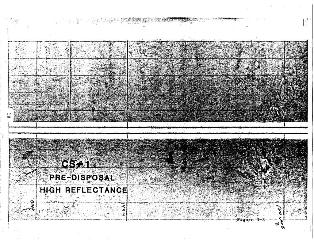
19 from New Haven harbor and Cap Site 2 sediment with sand from the outer portions of New Haven. A baseline bathymetric survey (Fig. 3-1) of Cap Site 1 - on 7 April, 1983 indicated a relatively flat bottom sloping only.5 m from north to south over the survey area. This survey was made a few days after disposal operations began and a slight elevation is apparent in the south center of the survey. A side scan sonar survey conducted on the same date indicates a predominant soft, silty bottom interspersed with concentrations of rough, high reflectance sediment (Fig. 3-2). The frequency of occurrence for these high reflectance areas increases toward the east in the general area of permit disposal operations at the "SP buoy and the previous Norwalk disposal operation. At the extreme east of the survey, the entire surface is composed of. high refl~ctance material. (Fig. 3-3). In the area immediately south of the disposal buoy dredged material on the bottom results in another area of high reflectance (Fig. 3-4) with characteristic crater signatures indicating the location of actual dumping. The combination of bathymetric and side scan data obtained at the site support the observation that initial disposal operations were not tightly controlled through dumping with the buoy immediately north of the scow. After emphasis was placed on the importance of point dumping, the subsequent operations were conducted close to the buoy and the Post-Black Rock disposal survey (Fig. 3-5) indicates a small mound less than 200 meters in diameter and approximately one meter thick was formed south of the buoy. 15
20 CAP SITE #1 PRE-DISPOSAL APRIL 1983 r---r---.,.---r-, o SCALE (ro) Figure 3-1
21 ~-. ~.';:,;~~~,~::~;~.:~,:~:~:}%- t~f,~~::?~v~~~~~:~t~(~w~'~t~~'\~ ~~~~Jb~:::';j~?~~{{~'~~"~\~'\::Y~:-';" ;-:::?~r~,:_:~~,w!/:~<~ 1?:" ':--.:/'- -~...:::;~.
22

23 ,~,..., f ;. :\ 'j}~t~~j:ke~~~~ 4--- \;.. > ~. - -'"1,
24 (> -''''',ic 78,,-- --:~ CAP SITE =IF 1. PRE-CAPPING APRIL 1983 N o o 80 SCALE (m) Figure 3-5
25 Diver observations at this site showed the presence of cohesive dredge material at distances approaching 200m south of the bouy1 however, some of this material may also have been the result of dumping at the MQR site which is immediately adjacent to CS 1. Attempts to deploy compaction stakes in natural bottom, which were long enough to penetrate and extend above the mound, appear to have failed. No stakes were found after completion of the disposal operation. 4. Cap Site 2 Cap Site 2 was established 700 m north of Cap site 1 to provide a site for capping with sand material. The baseline survey (Fig. 4-1) indicates a more complex topography than the CSI site, but still maintains a slope with a depth difference of one meter from north to south across the site. A shoal area with a topographic relief of one meter is also present in the northeast corner of the site. Sediment samples in that area were a coarse sand, indicating the possible presence of previous disposal in the area. An interim survey of the CS2 site (Fig. 4-2) was conducted on 28 April, 1983 and indicated the presence of an elliptical mound approximately 200 meters long in the east-west direction and 100 meters across in the north-south direction. Total elevation of the mound was generally less than one meter, and may reflect a lack of cohesion in sediments from the upper Black Rock Harbor area. A side scan survey of the site taken on 11 May, 1983 revealed a bottom very similar to that observed at Cap Site 1, 21
26 CAP SITE #2 PRE-DISPOSAL APRIL 1983,.0 t r---r---"r--- r---', o SCALE fm) Figure 4-1
27 >.I,--~ l'-r-f " -~,.+..~+_---'-----=~'=J_.'.~ \ +-~ CAP SITE #2 PRE-CAPPING <> o w '" APRIL o SCALE 1m) ~. / ii.b 17.B l;=::;::::;;=;:=;==i=:;::=;=;=::;=::;=;::::::;:=;=::;==l=i;=;:=;=:::;=:;=;;=;::::;=::;=l=;=;=::;=::;::::-;::-=;:-=~:::;-='~=lj" Figure 4-2
28 but with more frequent high reflectance areas and complete high reflectance on the east and northeast margins. In summary, Cap Site 2, while similar to the Cap Site 1 area on the baseline survey, may require special care in placement of the cap, since the material dumped at the buoy appears to have spread out over a larger portion of the bottom. A significant amount of material has been dumped since the interim survey was completed, and a Post-Disposal survey is planned for the near future to assess the results of the entire operation. 5. The disposal operation at the site selected for the Field Verification Program () has received the most attention of all the areas because of the large scope of the joint program between the Corps and EPA and because of the potential impact of dumping contaminated sediments from Black Rock Harbor at the CLIS site without subsequent capping procedures. Although most of the program is oriented toward biological tests to assess impacts of disposal, the initial stages of the program do reflect an emphasis on determining the distribution and physical properties of the material at the site. Several baseline surveys have been conducted at the site and results have previously been reported in DAMOS Contribution #23, describing the Site Selection of the Site. The last survey conducted prior to initial disposal operations took place on 10 December, 1980 and is shown in Figure 5-1. As discussed previously, the bottom at the site has a gentle slope 24
29 ._--_.._.._ _.._..._._ r--l-i-i---'--' -'---'1---'.1---'-1 ---'--I _IL..JI---'.I_+---'-----'---'--'---L-J_L-J'---'_--+---'-~. I!!! L-1 L~ =I~,L~9.2 ''-- =. nn: =_u ~ ~~ ~~ r PRE-DISPOSAL N 111 DECEMBER 1982 ~, e9. 4 -l--t lll.ij--... C>,.=_ > - r--r~--r , B BB 16B 41 e SCALE (m) I ~~~~~~~~~.~I~I-'I-~~dJ S ~~=.============================ Figure 5-1
30 toward the south with a depth difference of one meter over the extent of the survey area. A second side scan survey was conducted over the area on 26 April, 1983, which showed no change from previous surveys. The bottom at the site was generally a fine low reflectance silt with occasional concentrations of high reflectance zones, particularly toward the western margin of the site. The mud furrows discovered in earlier surveys oriented parallel to the direction of tidal flow were still present in the vicinity of the disposal buoy (Fig. 5-2) and to the south and east portions of the survey area. On 28 April, 1983, an interim survey was conducted to assess the conditions of the site as the first loads of sediment were deposited. The results of this survey (Fig. 5-3) indicated that a small mound had formed in the vicinity of the disposal buoy and therefore, that additional disposal should create the desired mound. A second interim bathymetric survey and associated side scan survey were conducted on 5 May, 1983, after disposal of approximately m 3 of dredged material had been completed. The results of this survey (Fig. 5-4) were also satisfactory as a small mound approximately 150 m in diameter had formed at the buoy with a topographic relief of more than one meter. Sediment samples taken at the same time revealed a covering of several centimeters thickness extending out to a range of 200 m on the east and slightly farther on the west side of the mound. This covering consisted of fine black organic silt with a high water content and low cohesiveness, which appeared to be quite fluid 26

31 ,-- ft, ---.,,; :.-' i.;: : >~, I
32 -~ ~ INTERIM "! ~ ~'G0= o ~<l 0 9.' 0 d \~:o \~.b. APRIL 1983 J~ 0 tv <::::> ~~ [J <i; ". " Co 0 "~ i ~ ~ I -,--,? ~ SCALE 1m) r I ~ Figure 5-3
33 , : [ ::r=~~~~~~-1~~~~-l-l~~7~2t5~1~.6~l-~~-lj-17~2~51~.~=== INTERIM MAY 1983 o 0-06.,.11 9.S 19.,---,-----,---,---, o SCALE 1m) ~ Figure 5-4
34 ~ ~ ---~- --~ and mixing with the natural fluff layer at the site. The side scan survey conducted on the same day revealed some interesting results. The mound created by the disposal operation was conspicuous as a region of high reflectance superimposed on the natural mud furrows at the site (Figs ). An interesting feature is also shown in Figure 5-7, which indicate an area of high reflectance created by leakage from the scow after disposal. The record shows the track of the scow as it left the disposal point heading south and then turning and proceeding west. This track probably reflects only the most recent dumping operation and apparently this material mixes with the natural sediment in a short time because only one track can be seen. However, this leakage does provide a mechanism for dispersion of some amount of contaminants even if the point dumping operation is successful. Following completion of the portion of Black Rock Harbor dredging, a Post Disposal Baseline survey was conducted on 19 May, This survey (Fig. 5-8 ) indicated that approximately 55,000 m 3 of material, measured by scow displacement, had formed a small elliptical mound slightly less than 200 meters in diameter and slightly more than two meters thick. Vertical profiles ~hrough the center of the mound (Fig. 5-9 ) support this observation. Problems with tracking the fathometer record by the on-board digitizer make the values on lane 18 invalid, however, post survey analysis of the analog record will provide correct data for future profiles and volume calculations. Sediment samples taken after completion of the survey 30

35 ",..,. ""."" "~-, "!'-:. '.'" ~ " ~ Figure 5-

36 Figure

37 j \.Ir ~ '{
38 -===~-::~--================--=-=~~=-=========; I t--+-F7~~m:T?~===~==~~~~==~===1l"""-'" f POST -DISPOSAL ( i MAY _-j'-"'niev~=0t-":~ET.n 7! r-~ -T-~l~ o SCALE [m) t--c-~h-"-"-'--f---'..l-- -I'-to';~---t-,-_c::.._~----t, ""'-0.., -If !! ~~===========~=.=0======n=51=.B=======5=1=.6======7251.4=~1 Figure 5-8
39 IS ,r. \, I ~.-... i : 18.0 ", /, / ~ ~ _/ ~ 19.0 ~... ". " --, BASELINE 28 APRIL 1983 Lane Interva 1: 25 m Vertical Exaggeration: 25X 0,,.-._-- ".-. - W ljl SOO S Distance (m) Lane 17 /", "--, \ t IS.0 /" 17.0 ". I : ~ ~ ~ 19.0 ~ 0 - ~".-~ I I I I I I I I I I I I~ Distance (m) Lane : 18.0 : ' , ~ --.-' '. ~ 0 '-'--.-."",,--- ' I I I I I I I I I I I I I SOO Distance (m) Lane : 18.0 ~ ~ ~ ~ ,. _._ '- -./ Distance (m) Lane 20 Figure 5-9
40 indicated the presence of Black Rock material to distances of less than 400 m in the north-south direction, just a trace at 400 m east, but substantial covering of material at 400w. At ranges less than 400 m the same black organic silt observed during the interim survey was present with varying thicknesses up to 5 cm at ranges of between 200 and 300 m. Although the mussel cage buoys at the 1000 m E station were moved and there are indications that dredged material may have been dumped in that vicinity, it does not appear that any Black Rock material was deposited. The samples indicative of dredged material at 1000 m E are spotty and contain relatively coarse sediment which probably came from another dredging location. In summary, the disposal operation at the appears successfult however, the potential for movement of sediment does exist because of the high water content, fluid muds on the margins of the mound. Careful monitoring during the immediate post-disposal period is essential to assess the potential impact should this movement occur
US ARMY CORPS OF ENGINEERS New England District BUILDING STRONG
 US ARMY CORPS OF ENGINEERS New England District STUDIES Sediment Sampling Biological Sampling (benthic community analysis) Hydroacoustic Surveys (side scan sonar, bathymetry) Remotely Operated Vehicle
Disposal Area Monitoring System DAMOS
 Monitoring Cruise at the Central Long Island Sound Disposal Site July 1986 Disposal rea Monitoring System DMOS Contribution 63 pril 1990 US rmy Corps of Engineers New England Division REPORT DOCUMENTTION
Introduction to Acoustic Remote Sensing and Seafloor Mapping (AE4-E13) May 19, 2010
 May 19, 2010") Introduction to Acoustic Remote Sensing and Seafloor Mapping (AE4-E13) May 19, 2010 1 Delft Vermelding Institute onderdeel of Earth organisatie Observation and Space Systems Why Acoustic Remote Sensing?
Introduction to Acoustic Remote Sensing and Seafloor Mapping (AE4-E13) May 19, 2010 1 Delft Vermelding Institute onderdeel of Earth organisatie Observation and Space Systems Why Acoustic Remote Sensing?
Disposal Area. Monitoring System DAMOS. o At: 0 S. Monitoring Cruise at the Central Long Island Sound Disposal Site July 1996.
 Monitoring Cruise at the Central Long Island Sound Disposal Site July 1996 Disposal Area ; Monitoring System DAMOS o At: 0 S "iiiij;nspc>bo;w:.. 6--,DAIHQ---s-,s,-..., Contribution 120 May 1998 US Army
Changes in Geomorphology and Backscatter Patterns in Mount Misery Shoal, Long Island Sound as Revealed through Multiple Multibeam Surveys
 Changes in Geomorphology and Backscatter Patterns in Mount Misery Shoal, Long Island Sound as Revealed through Multiple Multibeam Surveys Laurie A. Zaleski Laurie.Zaleski@msrc.sunysb.edu, Roger D. Flood
Highland Lake Bathymetric Survey
 Highland Lake Bathymetric Survey Final Report, Prepared For: The Town of Highland Lake 612 Lakeshore Drive Oneonta, AL 35121 Prepared By: Tetra Tech 2110 Powers Ferry Road SE Suite 202 Atlanta, GA 30339
PTM: A Lagrangian Particle Tracking Model. Joseph Gailani
 PTM: A Lagrangian Particle Tracking Model Joseph Gailani Joe.Z.Gailani@usace.army.mil OUTLINE Motivation for sediment/constituent modeling system Objectives of modeling system Description of PTM PTM Example
MARINE GEOLOGY & GEOGRAPHY
 MARINE GEOLOGY & GEOGRAPHY Bathymetry BATHYMETRY BATHYMETRY THE UNDERWATER EQUIVALENT TO TOPOGRAPHY THE STUDY OF WATER DEPTH A BATHYMETRIC MAP SHOWS FLOOR RELIEF OR TERRAIN AS CONTOUR LINES Bathymetry
Mound Study Project Cape Fear, North Carolina Report Summary VIMS Reports: CHSD to CHSD EHI Project No
 Mound Study Project Cape Fear, North Carolina Report Summary VIMS Reports: CHSD-2003-02 to CHSD-2003-06 EHI Project No. 6000.21 February 2003 Final VIMS Report CHSD-2003-01 Prepared for Evans-Hamilton,
MaxDepth Aquatics, Inc.
 MaxDepth Aquatics, Inc. Bathymetry of Mirror Pond From Newport Bridge to Galveston Bridge Prepared for the City of Bend By Joseph Eilers & Benn Eilers MaxDepth Aquatics, Inc. Bend, OR June 2005 INTRODUCTION
6. Mapping the Seafloor
 6. Mapping the Seafloor Centuries ago sailors ventured into unknown oceans to discover new lands. They had no accurate charts or maps to guide them to new places or back to home ports. Imagine how relieved
CHAPTER 28. PHYSIOGRAPHY Cook Inlet Drainages
 PEBBLE PROJECT ENVIRONMENTAL BASELINE DOCUMENT 2004 through 2008 CHAPTER 28. PHYSIOGRAPHY Cook Inlet Drainages PREPARED BY: Knight Piésold Ltd. PHYSIOGRAPHY COOK INLET DRAINAGES TABLE OF CONTENTS TABLE
Anderson-Ketron PSDDA Disposal Site Fate and Transport Modeling
 Pierce County Washington Anderson-Ketron PSDDA Disposal Site Fate and Transport Modeling Design Memorandum September 2014 Table of Contents 1 Introduction... 3 1.1 Purpose and Scope... 3 1.2 Project Description:
ANALYSIS OF SEISMIC PROFILES AND SIDE-SCAN SONAR RECORDS FROM LOWER NEW YORK HARBOR, A PROGRESS REPORT. Roger D. Flood Vicki Lynn Ferrini
 45 ANALYSIS OF SISMIC PROFILS AND SID-SCAN SONAR RCORDS FROM LOWR NW YORK HARBOR, A PROGRSS RPORT Roger D. Flood Vicki Lynn Ferrini Marine Sciences Research Center State University of New York, Stony Brook,
Earth / Environmental Science. Ch. 14 THE OCEAN FLOOR
 Earth / Environmental Science Ch. 14 THE OCEAN FLOOR The Blue Planet Nearly 70% of the Earth s surface is covered by the global ocean It was not until the 1800s that the ocean became an important focus
Appendix I. Dredged Volume Estimates. Draft Contractor Document: Subject to Continuing Agency Review
 Appendix I Dredged Volume Estimates Draft Contractor Document: Subject to Continuing Agency Review Interoffice Correspondence Date: April 6, 2007 To: L. Bossi (WHI) Copy: S. Thompson (WHI), B. Fidler (NNJ)
Annual transport rates at two locations on the fore-slope.
 Sediment Transport by Currents Fore-slope Sediment transport rates and sediment concentrations were computed from the hydrodynamic model runs as well as from direct measurements of current velocities at
Notes and Summary pages:
 Topographic Mapping 8.9C Interpret topographical maps and satellite views to identify land and erosional features and predict how these shapes may be reshaped by weathering ATL Skills: Communication taking
SEDIMENT TRANSPORT IN RIVER MOUTH ESTUARY
 SEDIMENT TRANSPORT IN RIVER MOUTH ESTUARY Katsuhide YOKOYAMA, Dr.Eng. dredge Assistant Professor Department of Civil Engineering Tokyo Metropolitan University 1-1 Minami-Osawa Osawa, Hachioji,, Tokyo,
Bathymetry Measures the vertical distance from the ocean surface to mountains, valleys, plains, and other sea floor features
 1 2 3 4 5 6 7 8 9 10 11 CHAPTER 3 Marine Provinces Chapter Overview The study of bathymetry determines ocean depths and ocean floor topography. Echo sounding and satellites are efficient bathymetric tools.
A 22 YEAR RECORD OF DREDGED MATERIAL MONITORING: RESULTS FROM THE FIELD VERIFICATION PROGRAM (FVP) MOUND IN LONG ISLAND SOUND
 MOUND IN LONG ISLAND SOUND") A YEAR RECORD OF DREDGED MATERIAL MONITORING: RESULTS FROM THE FIELD VERIFICATION PROGRAM (FVP) MOUND IN LONG ISLAND SOUND P.L. Myre 1, J.D. Germano, D.A. Carey 3, and T.J. Fredette ABSTRACT In the spring
A YEAR RECORD OF DREDGED MATERIAL MONITORING: RESULTS FROM THE FIELD VERIFICATION PROGRAM (FVP) MOUND IN LONG ISLAND SOUND P.L. Myre 1, J.D. Germano, D.A. Carey 3, and T.J. Fredette ABSTRACT In the spring
B. Topographic maps are also called. contour maps
 Topographic Maps Introduction A. Topographic maps are essential tools in geologic and engineering studies because they show the configuration of Earth's surface in remarkable detail and permit one to measure
Monitoring Survey Over Boston Harbor CAD Cell M19. Disposal Area Monitoring System DAMOS
 Monitoring Survey Over Boston Harbor CAD Cell M19 Disposal Area Monitoring System DAMOS Contribution 148 October 2003 REPORT DOCUMENTATION PAGE form approved OMB No. 0704-0188 Public reporting concern
Variability in Geotechnical Properties of Sediments and Dredged Materials
 Variability in Geotechnical Properties of Sediments and Dredged Materials PURPOSE: This technical note provides an overview of selected uncertainties involved in estimating or characterizing pre-dredged
THE QUATERNARY GEOLOGY OF NEWARK BAY AND KILL VAN KULL CHANNEL, NEW YORK AND NEW JERSEY. and
 THE QUATERNARY GEOLOGY OF NEWARK BAY AND KILL VAN KULL CHANNEL, NEW YORK AND NEW JERSEY Stephanie Beda, W. Bruce Ward, William Murphy, Robert Fleming, Gary Fleming, Beckett Boyd Earthworks LLC 27 Glen
Elevations are in meters above mean sea level. Scale 1:2000
 12.001 LAB 7: TOPOGRAPHIC MAPS Due: Monday, April 11 PART I: CONTOURING AND PROFILES (20 PTS) 1. Contour this area map using a 5 meter contour interval. Remember some fundamental rules of contour lines,
Joint Federal Agency Submerged Aquatic Vegetation Survey Guidance for the New England Region Updated August 11, 2016
 Joint Federal Agency Submerged Aquatic Vegetation Survey Guidance for the New England Region Updated August 11, 2016 FOREWORD This guidance is the result of on-going interagency collaboration between the
Final Survey/Data Report
 US ARMY CORPS OF ENGINEERS New England District Contract No. DACW33-03-D-004 Delivery Order No. 05 November 2004 Final Survey/Data Report Boston Harbor Deep Draft Navigation Improvement Project Biological
Map shows 3 main features of ocean floor
 Map shows 3 main features of ocean floor 2017 Pearson Education, Inc. Chapter 3 Marine Provinces 2017 Pearson Education, Inc. 1 Chapter 3 Overview The study of bathymetry determines ocean depths and ocean
Estimated Sediment Volume: Bridge Street Dam Impoundment, Royal River, Yarmouth, Maine
 University of Southern Maine USM Digital Commons Publications Casco Bay Estuary Partnership (CBEP) 2015 Estimated Sediment Volume: Bridge Street Dam Impoundment, Royal River, Yarmouth, Maine Stantec Follow
DEPARTMENT OF THE ARMY WATERWAYS EXPERIMENT STATION. CORPS OF ENGINEERS P. 0. BOX 631 VICKSBURG. MISSISSIPPI 39180
 DEPARTMENT OF THE ARMY WATERWAYS EXPERIMENT STATION. CORPS OF ENGINEERS P. 0. BOX 631 VICKSBURG. MISSISSIPPI 39180 IN REPLY REF6R TO: WESYV 31 July 1978 SUBJECT: Transmittal of Technical Report D-78-34
Chapter Overview. Bathymetry. Measuring Bathymetry. Measuring Bathymetry
 CHAPTER 3 Marine Provinces Chapter Overview The study of bathymetry determines ocean depths and ocean floor topography. Echo sounding and satellites are efficient bathymetric tools. Most ocean floor features
POST CABLE INSTALLATION THERMAL MONITORING PROGRAM LONG ISLAND REPLACEMENT CABLE PROJECT NORWALK, CT OSI JOB# 08ES069
 28 July 2009 Mark D. Driscoll, M.S. Senior Water Resources Scientist. 888 Worcester Street, Suite 2 Wellesley, MA 02482 SUBJECT: FINAL REPORT POST CABLE INSTALLATION THERMAL MONITORING PROGRAM LONG ISLAND
SUBJECT INDEX. ~ ~5 physico-chemical properties 254,255 Redox potential 254,255
 Aggregates: beds formed by deposition 81,82 breakup by fluid shear, introduction 85,86 deposition from flowing water 80 implications in cohesive sediment transport 102-105 needs for further research 83
ENGINEERING APPROACHES TO SHORELINE PLACEMENT FROM COAST TO COAST
 ENGINEERING APPROACHES TO SHORELINE PLACEMENT FROM COAST TO COAST 237 237 237 217 217 217 200 200 200 0 0 0 163 163 163 131 132 122 80 119 27 252 174.59 83 36 118 110 135 120 112 92 56 62 102 130 Comparing
Near-Field Sturgeon Monitoring for the New NY Bridge at Tappan Zee. Quarterly Report October 1 December 31, 2014
 Near-Field Sturgeon Monitoring for the New NY Bridge at Tappan Zee Quarterly Report October 1 December 31, 2014 Prepared by AKRF, Inc. 7250 Parkway Drive, Suite 210 Hanover, MD 21076 for New York State
Imagine the result Sediment Sampling Plan. 1½-Mile Reach of the Housatonic River. General Electric Company Pittsfield, Massachusetts
 Imagine the result General Electric Company Pittsfield, Massachusetts 2012 Sediment Sampling Plan 1½-Mile Reach of the Housatonic River March 2012 2012 Sediment Sampling Plan 1½-Mile Reach of the Housatonic
Disposal Area Monitoring System ( Damos/ Benthic Macro Fauna Study Central Long Island Sound Disposal Site. us Army Corps
 Benthic Macro Fauna Study Central Long Island Sound Disposal Site Disposal Area Monitoring System ( Damos/ i 'Contribution 24! August 983 us Army Corps of Engineers New England Division A STUDY OF THE
Bishopville Prong Study
 Bathymetric and Sediment Assessment in the Bishopville Prong of St. Martin River Darlene V. Wells, Richard A. Ortt, Jr., and Stephen Van Ryswick Funded by MCBP 2011-2012 Implementation Grant Objectives
Clyde River Landslide
 Clyde River Landslide Department of Geology, Perkins Hall, University of Vermont, Burlington, VT 05405 Abstract: This paper investigates a landslide on the Clyde River in Newport, Vermont. The landslide
MARINE GEOLOGY & GEOGRAPHY
 MARINE GEOLOGY MARINE GEOLOGY & GEOGRAPHY Marine Geology 4 LAYERS OF THE EARTH CRUST THICKNESS: VARIES BETWEEN OCEAN & CONTINENTS 5-40 KM STATE: SOLID ELEMENTS: SILICON, ALUMINUM, CALCIUM, SODIUM, POTASSIUM
Disposal Area Monitoring System
 - Monitoring Cruise at the Western Long Island Sound Disposal Site July 1996 1, 'I Disposal Area Monitoring System,DAMOS DAM 0 S DISPOSAL AREA MONITORING SYSTEM Contribution 119 F May 1998 us Army Corps
Changes in bottom morphology of Long Island Sound near Mount Misery Shoal as observed through Repeated Multibeam Surveys
 Changes in bottom morphology of Long Island Sound near Mount Misery Shoal as observed through Repeated Multibeam Surveys Laurie A. Zaleski Laurie.Zaleski@msrc.sunysb.edu Roger D. Flood rflood@notes.cc.sunysb.edu
Redwood City Harbor, California, Navigation Improvement Feasibility Study. Appendix D. Geotechnical Engineering. DRAFT April 2015
 1 Redwood City Harbor, California, Navigation Improvement Feasibility Study Appendix D Geotechnical Engineering DRAFT April 2015 2 Contents 1 Purposes of Report... 3 2 Background... 3 3 References and
Appendix G.19 Hatch Report Pacific NorthWest LNG Lelu Island LNG Maintenance Dredging at the Materials Offloading Facility
 Appendix G.19 Hatch Report Pacific NorthWest LNG Lelu Island LNG Maintenance Dredging at the Materials Offloading Facility Project Memo H345670 To: Capt. David Kyle From: O. Sayao/L. Absalonsen December
June 2018 Sediments and Dredging at GBR Ports
 June 2018 Sediments and Dredging at GBR Ports Reef 2050 Long Term Sustainability Plan The Great Barrier Reef is over 2000 km long and covers an area of approximately 350,000 square kilometres. It is a
FINMARINET: Inventories and Planning for the Marine Natura 2000 Network in Finland. A.2 Geological inventories of the seafloor Final Report
 LIFE07 NAT/FIN/000151 FINMARINET: Inventories and Planning for the Marine Natura 2000 Network in Finland A.2 Geological inventories of the seafloor Final Report Geological Survey of Finland, GTK 1. Introduction
Seafloor Morphology. Techniques of Investigation. Bathymetry and Sediment Studies
 Seafloor Morphology I f we select a grid for the surface of the earth (i.e. 5 km 2 ) and assign it an average elevation in relation to sea level, we can construct a graph of elevation versus area of the
Natural hazards in Glenorchy Summary Report May 2010
 Natural hazards in Glenorchy Summary Report May 2010 Contents Glenorchy s hazardscape Environment setting Flood hazard Earthquakes and seismic hazards Hazards Mass movement Summary Glossary Introduction
Monitoring Survey at the Mark Island Disposal Site July Disposal Area Monitoring System DAMOS
 Monitoring Survey at the Mark Island Disposal Site July 2002 Disposal Area Monitoring System DAMOS Contribution 143 February 2003 REPORT DOCUMENTATION PAGE form approved OMB No. 0704-0188 Public reporting
ENGINEERING WITH NATURE: NEARSHORE BERM PLACEMENTS AT FORT MYERS BEACH AND PERDIDO KEY, FLORIDA, USA
 1 ENGINEERING WITH NATURE: NEARSHORE BERM PLACEMENTS AT FORT MYERS BEACH AND PERDIDO KEY, FLORIDA, USA KATHERINE E. BRUTSCHÉ 1, PING WANG 2, JULIE D. ROSATI 1, CHERYL E. POLLOCK 1 1. U.S. Army Engineer
ARE YOU READY TO THINK? Look at the first slide THINK PAIR SHARE!
 ARE YOU READY TO THINK? Look at the first slide THINK PAIR SHARE! WHAT PROMINENT FEATURE CAN YOU IDENTIFY IN THIS PICTURE? What do you think the different colors represent? Who might find such a picture
56H. This system allows definition of points on the Earth s surface to within 100 meters. Page 20. Navigation Systems Basics of Maps
 Grid References Many maps are provided with the standard grid overlaying them. This provides a simple and accurate method for finding features on the map. It is a network of intersecting parallel lines
Name: Mid-Year Review #2 SAR
 Name: Mid-Year Review #2 SAR Base your answers to questions 1 through 3 on on the diagram below, which shows laboratory materials used for an investigation of the effects of sediment size on permeability,
Baltic Sea Research Institute
 Baltic Sea Research Institute Warnemuende (IOW) Cruise Report No. 44/96/ 04 R/V "A.v.Humboldt" MESODYN Cruise 01 to 12 March 1996 Stolpe Furrow / Baltic Sea This report is based on preliminary data and
WHITE POINT LANDSLIDE GEOTECHNICAL INVESTIGATION November 29, 2012 Status Report
 Gary Lee Moore, P.E., City Engineer Vince Jones, P.E., Deputy City Engineer WHITE POINT LANDSLIDE GEOTECHNICAL INVESTIGATION November 29, 2012 Status Report White Point Landslide Geotechnical Investigation
Earth Science Lesson Plan Quarter 2, Week 10, Day 1
 Earth Science Lesson Plan Quarter 2, Week 10, Day 1 Outcomes for Today Standard Focus: PREPARE 1. Background knowledge necessary for today s reading. Beaches are created by the actions of waves, tides,
Material Workshop. Galveston District 2012 Beneficial Use of Dredged. Material Workshop. Custodians of the Coast
 Galveston District 2012 Beneficial Use of Dredged Material Workshop Galveston District 2012 Beneficial Use of Dredged Material Workshop US Army Corps of Engineers BUILDING STRONG Welcome Opening Remarks
Decline of Lake Michigan-Huron Levels Caused by Erosion of the St. Clair River
 Decline of Lake Michigan-Huron Levels Caused by Erosion of the St. Clair River W.F. & Associates Coastal Engineers (in association with Frank Quinn) April 13, 2005 Outline Problem Definition Understanding
The Arctic - A New Frontier The geological, environmental and engineering challenges for submarine telecommunication cables
 The Arctic - A New Frontier The geological, environmental and engineering challenges for submarine telecommunication cables Ryan Wopschall 5 September 2013 Oceanology International China, Shanghai Fugro
Seismic Reflection Imaging across the Johnson Ranch, Valley County, Idaho
 Seismic Reflection Imaging across the Johnson Ranch, Valley County, Idaho Report Prepared for the Skyline Corporation Lee M. Liberty Center for Geophysical Investigation of the Shallow Subsurface (CGISS)
CHAPTER 126 ^^^C^SR, SEDIMENTATION STUDIES ON THE NIGER RIVER DELTA
 CHAPTER 126 SEDIMENTATION STUDIES ON THE NIGER RIVER DELTA Ramiro Mayor-Mora, D. Eng. (1) Preben Mortensen, M.Sc. (2) Jorgen Fredsoe, M.Sc. (2) 1. Introduction An area of the Niger River Delta was studied
The Coast: Beaches and Shoreline Processes
 1 2 3 4 5 6 7 8 9 The Coast: es and Shoreline Processes Trujillo & Thurman, Chapter 10 Oceanography 101 Chapter Objectives Recognize the various landforms characteristic of beaches and coastal regions.
IN SITU SPECIFIC GRAVITY VS GRAIN SIZE: A BETTER METHOD TO ESTIMATE NEW WORK DREDGING PRODUCTION
 IN SITU SPECIFIC GRAVITY VS GRAIN SIZE: A BETTER METHOD TO ESTIMATE NEW WORK DREDGING PRODUCTION Nancy Case O Bourke, PE 1, Gregory L. Hartman, PE 2 and Paul Fuglevand, PE 3 ABSTRACT In-situ specific gravity
Sediment Traps. CAG Meeting May 21, 2012
 Sediment Traps CAG Meeting May 21, 2012 Agenda Background Fundamentals of Sediment Transport Sediment Trap Existing Information Next Steps 2 The Site Saginaw River 22 mile river beginning at confluence
The Coast: Beaches and Shoreline Processes Trujillo & Thurman, Chapter 10
 The Coast: es and Shoreline Processes Trujillo & Thurman, Chapter 10 Oceanography 101 Chapter Objectives Recognize the various landforms characteristic of beaches and coastal regions. Identify seasonal
3. UNDERWAY GEOPHYSICS 1
 Sawyer, D.S., Whitmarsh, R.B., Klaus, A., et al., 1994 Proceedings of the Ocean Drilling Program, Initial Reports, Vol. 149 3. UNDERWAY GEOPHYSICS 1 Shipboard Scientific Party 2 EQUIPMENT AND METHODS Navigation
At the Edge of the Continent
 Islands in the Stream 2002: Exploring Underwater Oases At the Edge of the Continent FOCUS Bathymetry of the South Atlantic Bight continental shelf and upper shelf-edge GRADE LEVEL 9-12 (Earth Science)
Meteor-Cruise M 75 / 2 Short Cruise Report Chief scientist: Dr. Jürgen Pätzold Universität Bremen Bremen / Germany
 Meteor-Cruise M 75 / 2 Short Cruise Report Chief scientist: Dr. Jürgen Pätzold Universität Bremen Bremen / Germany Dar es Salaam Dar es Salaam Febr. 06 th Febr. 24 th, 2008 1 SHORT CRUISE REPORT RV METEOR
Decoding Topographic Maps
 Name: Date: 1. Base your answer(s) to the following question(s) on the topographic map below and on your knowledge of Earth science. Letters A through F represent locations on the map. What is the contour
Applying Electrical Resistivity Methods for Measuring Dredged Material Density in Hopper Bins
 DRP-3-07 November 1992 Dredging Technical Research Notes Applying Electrical Resistivity Methods for Measuring Dredged Material Density in Hopper Bins Purpose This technical note provides information on
Approximately how many inches of average yearly precipitation does Rochester, New York, receive?
 1. Base your answer to the following question on the isoline map below, which shows the average yearly precipitation, in inches, across New York State. Approximately how many inches of average yearly precipitation
GSA DATA REPOSITORY
 GSA DATA REPOSITORY 2009206 Miner et al. Supplemental Material Bathymetric Survey Methods The bathymetric data for the area were gathered using a single-beam bathymetric survey rig mounted aboard a 21-foot
Coastal Inlets Research Program US Army Corps of Engineers Engineering Research and Development Center
 Coastal Inlets Research Program US Army Corps of Engineers Engineering Research and Development Center Site of Moriches Inlet Nov. 1951 Julie Dean Rosati and Nicholas C. Kraus, CIRP Program Manager Shinnecock
A GPR ASSESSMENT OF THE PREHISTORIC NAPLES CANAL NAPLES, FLORIDA ARCHAEOLOGICAL AND HISTORICAL CONSERVANCY, INC.
 A GPR ASSESSMENT OF THE PREHISTORIC NAPLES CANAL NAPLES, FLORIDA ARCHAEOLOGICAL AND HISTORICAL CONSERVANCY, INC. AHC TECNICAL REPORT NO. 1004 DECEMBER 2013 A GPR ASSESSMENT OF THE PREHISTORIC NAPLES CANAL
U.S. DEPARTMENT OF THE INTERIOR U.S. GEOLOGICAL SURVEY MEASUREMENTS OF SAND THICKNESSES IN GRAND CANYON,
 U.S. DEPARTMENT OF THE INTERIOR U.S. GEOLOGICAL SURVEY MEASUREMENTS OF SAND THICKNESSES IN GRAND CANYON, ARIZONA, AND A CONCEPTUAL MODEL FOR CHARACTERIZING CHANGES IN SAND-BAR VOLUME THROUGH TIME AND SPACE
Using Map and Compass Together
 Using Map and Compass Together In situations where you foresee a potential evacuation on foot, where there are no roads, and no indication as to the direction of travel (i.e., road signs), it is recommended
3. MARINE HABITAT RESTORATION
 Feasibility Study for Restoration of Titlow Lagoon Fish Passage South Puget Sound Salmon Enhancement Group 3. MARINE HABITAT RESTORATION Marine habitat restoration at Titlow Park could include restoration
Environmental impact assessment study of the new offshore dumping sites for Šventoji port in Lithuania
 Environmental impact assessment study of the new offshore dumping sites for Šventoji port in Lithuania Introduction Summary In 2003 Lithuanian Ministry of Transport initiated the preparation of feasibility
An Update to EPA s Conceptual Site Model for the Lower Passaic River: An Examination of the Most Recent Results
 An Update to EPA s Conceptual Site Model for the ower Passaic River: An Examination of the Most Recent Results Edward A. arvey, Alice Yeh 2, Solomon bondo-tugbawa, Juliana Atmadja, John Kern 3, AmyMarie
Disposal Area Monitoring System DAMOS
 Monitoring Survey at the Cape Cod Bay Disposal Site August 2003 Disposal Area Monitoring System DAMOS Cape Cod Bay, Massachusetts 5 Duxbury Massachusetts Bay Provincetown Long Point Contribution 157 August
Varying Bathymetric Data Collection Methods and their Impact on Impoundment Volume and Sediment Load Calculations I.A. Kiraly 1, T.
 Varying Bathymetric Data Collection Methods and their Impact on Impoundment Volume and Sediment Load Calculations I.A. Kiraly 1, T. Sullivan 2 1 Gomez and Sullivan Engineers, D.P.C., 41 Liberty Hill Road,
Regional-scale understanding of the geologic character and sand resources of the Atlantic inner continental shelf, Maine to Virginia
 Regional-scale understanding of the geologic character and sand resources of the Atlantic inner continental shelf, Maine to Virginia Workshop on Dredging, Beach Nourishment and Bird Conservation Atlantic
Disposal Area Monitoring System DAMOS
 Disposal Plume Tracking and Assessment at the Rhode Island Sound Disposal Site Summer 2004 Disposal Area Monitoring System DAMOS Rhode Island Brenton Point Point Judith Contribution 167 October 2005 Block
Assessment of the Hood River Delta Hood River, Oregon
 Assessment of the Hood River Delta Hood River, Oregon Pacific Northwest Waterways Association Annual Meeting October 13, 2010 Michael McElwee, Executive Director Port of Hood River Overview U.S. Army Corps
Island Design. UMRS EMP Regional Workshop. Presentation for the
 Island Design Presentation for the UMRS EMP Regional Workshop by Jon Hendrickson Hydraulic Engineer Regional Technical Specialist, Water Quality and Habitat Restoration August 17 19, 2005 Project Delivery
Linking Inlet Hydrodynamics and Morphologic Response at Oregon Inlet, NC
 Linking Inlet Hydrodynamics and Morphologic Response at Oregon Inlet, NC Prepared for: Sharon Ahlers Engineering Communications Program Cornell University Prepared by: Justin Vandever School of Civil and
Observation of Deep Seafloor by Autonomous Underwater Vehicle
 Indian Journal of Geo-Marine Sciences Vol. 42 (8), December 2013,pp. 1028-1033 Observation of Deep Seafloor by Autonomous Underwater Vehicle Tamaki Ura 1 Underwater Technology Research Center, Institute
Observation of Deep Seafloor by Autonomous Underwater Vehicle
 Observation of Deep Seafloor by Autonomous Underwater Vehicle Tamaki Ura 1 Underwater Technology Research Center Institute of Industrial Science, The University of Tokyo 4-6-1, Komaba, Minato, Tokyo, Japan
Monitoring of Alabama Berms
 DRP-1-08 July 1992 Dredging Technical Research Notes Monitoring of Alabama Berms Purpose This technical note presents insights into how, why, and when dredged material berms move, based on the gradual
Wilson Bay Sediment Profile Imaging: 1. Instrument Test
 Environment Waikato Technical Report 2006/09 Wilson Bay Sediment Profile Imaging: 1. Instrument Test Prepared by: Kay C. Vopel, Greig Funnell (National Institute of Water & Atmospheric Research Ltd) For:
EROSIONAL FEATURES. reflect
 reflect Have you ever looked at the land around you and wondered what processes shaped what you see? Perhaps you see mountains, valleys, rivers, or canyons. Do you know how long these geologic features
Identification of Lateral Spread Features in the Western New Madrid Seismic Zone J. David Rogers and Briget C. Doyle
 Identification of Lateral Spread Features in the Western New Madrid Seismic Zone J. David Rogers and Briget C. Doyle Department of Geological Engineering University of Missouri-Rolla rogersda@umr.edu doyle@hope.edu
Appendix G.18 Hatch Report Pacific NorthWest LNG Lelu Island LNG Potential Impacts of the Marine Structures on the Hydrodynamics and Sedimentation
 Appendix G.18 Hatch Report Pacific NorthWest LNG Lelu Island LNG Potential Impacts of the Marine Structures on the Hydrodynamics and Sedimentation Patterns Project Memo H345670 To: Capt. David Kyle From:
H.A.R.S. PRA #1 (Historic Area Remediation Site)
") H.A.R.S. PRA #1 (Historic Area Remediation Site) 2009 Multibeam Bathymetry TABLE OF CONTENTS Page LIST OF TABLES 2 LIST OF FIGURES 3 1.0 INTRODUCTION 4 2.0 OBJECTIVE 4 3.0 PROCEDURE 4 3.1 DATA ACQUISITION
H.A.R.S. PRA #1 (Historic Area Remediation Site) 2009 Multibeam Bathymetry TABLE OF CONTENTS Page LIST OF TABLES 2 LIST OF FIGURES 3 1.0 INTRODUCTION 4 2.0 OBJECTIVE 4 3.0 PROCEDURE 4 3.1 DATA ACQUISITION
Iceberg Plough Marks in the Vicinity of the Norwegian Trough
 Iceberg Plough Marks in the Vicinity of the Norwegian Trough ROBERT H. BELDERSON & JOHN B. WILSON Belderson, R. H. & Wilson, J. B.: Iceberg plough marks in the vicinity of the Norwegian Trough. Norsk Geologisk
Historical Bathymetric Data for the Lower Passaic River
 Historical Bathymetric Data for the Lower Passaic River 4th Passaic River Symposium June 22nd, 2010 Dr. William Hansen Jeffrey Cranson Worcester State College Project Supported by The Hudson River Foundation
APPENDIX O. Sediment Modeling of Dredging off Lelu Island, Prince Rupert, BC Canada, and Disposal of Dredgate at Brown Passage
 APPENDIX O Sediment Modeling of Dredging off Lelu Island, Prince Rupert, BC Canada, and Disposal of Dredgate at Brown Passage Sediment Modeling of Dredging off Lelu Island, Prince Rupert, BC Canada, and
Sediment Resuspension by Dredges: Defining the Issues
 Sediment Resuspension by Dredges: Defining the Issues Doug Clarke Environmental Laboratory U.S. Army Corps of Engineers Engineer Research and Development Center Dredge types Definition Related processes