LOZAR RADAR INTRODUCTORY PRESENTATION COAL SURVEYING
|
|
|
- Prudence McDowell
- 5 years ago
- Views:
Transcription


1 LOZAR RADAR INTRODUCTORY PRESENTATION COAL SURVEYING

2 ABOUT LOZAR RADAR Lozar Radar is a ground-scanning device, which verifies and investigates the presence of mineral resources and geological features, with unrivalled clarity and speed up to a depth of 200m. Existing ground penetrating radar technologies traditionally only penetrate to 25 meters in conducive conditions. The radar technology is derived from a requirement of the Russian space program to scan for water on Mars. Our radar is a leading technological tool, where, with minimum cost, information can be obtained about the geological structure of the section and prospective areas identified with real time speed.
3 WHY LOZAR RADAR? FINANCIAL ADVANTAGE Advantages of Lozar Radar Technology to penetrate to depths of up to 200m Versatile and highly portable Delivers financial savings to the client: Low cost & accurate resource targeting Verification of drill hole data More powerful - 100,000 times the power of traditional GPR Our surveys enable drilling and trenching to be targeted more efficiently Localised and light operational footprint Reduced drilling expenditure Real time data processing and analysis Improved mine planning Lozar can accurately locate: Minimal impact on the environment and surrounding operations Speed of data collection: acquisition of up to 4km of line surveyed profiles a day. Faults & Voids Bedrock Contact & Ore Bodies Alluvial Horizons & Oxidised Zones
4 ADVANTAGES IN EXPLORATION Traditional methods of IP or Seismics, or trenching and combining with drilling in early stages of resource identification can be replaced with Radar and less drilling: With an overall decrease in expenditure Improving on the required level of accuracy and quality of data No comprising on quantifying resource estimates Faster acquisition with real time display Reduction in initial drilling to define conductive/dielectric areas of interest Cost Analysis: Can provide a detailed costing for a comparative survey to illustrate the potential savings upon obtaining past expenditure details on the traditional survey methods of IP and drilling. More powerful - 100,000 times the power of traditional GPR

5 SURVEYING FOR COAL 4

6 COAL RADARGRAM EXAMPLE # 1 Coal bed Coal bed DH Data Above 5


7 COAL SCHEMATIC EXAMPLE # 1 Drill hole used for calibration Coal bed Coal bed Schematic representation of Radargram on previous page 6


8 COAL RADARGRAM EXAMPLE # 2 Distance 600m Down hole Reference in vicinity of profile Coal bed Coal bed 7
")
9 COAL RADARGRAM EXAMPLE # 3 (COMPLETE PROFILE) 8

10 COAL RADARGRAM EXAMPLE # 3 (SECTION) Sandstone / shale mix Shale Coal Layer 2 Thermal Coal Coal Layer 3 Coking Coal Sandstone Bedrock 9

11 COAL CASE STUDY #1 AFRICA Start of Profile Top of Pit Wall Coal & Shale Seams Target Coal Seam Fig 10 10
 so calibration was possible from visual observation.")
12 COAL CASE STUDY # 1 AFRICA Radargram below displays the Overburden, Shale and Coal Layers, contact with Bedrock and Faulting. The profile is 750m in length and took 30 mins to collect and 4 hours to process. The profile was taken from the coal pit wall (previous slide) so calibration was possible from visual observation. Start Distance (750 m) Finish Overburden Shale Coal Layer Coal bed Bedrock Depth (110m) Undulation is very pronounced due to compressing of image. 11 Faults
13 COAL CASE STUDY #1 AFRICA To survey the heavily faulted zone to position fault locations and the coal seams. Profiles Taken SURVEY OBJECTIVES: 1. Estimate volume & location of resource 2. Assist client with planning a targeted drilling program & reduce the # of DH required. Faults 12

14 COAL CASE STUDY # 2 AFRICA Task: Concession Drilled in 1970 s Run profiles through the DH, confirm presence and structure of coal. Coal bed Above: Whole profile is 2.6km long, and passes through 2 drill holes. Note, the profile is compressed for ease of viewing the coal does not roll so much in reality. The drilling identified the roof of the coal. Left: Detail the drill hole record was for coal roof to be seen at 77m. The profile shows geophysical boundaries that are most likely the upper coal resource. It is not known what the lower black signatures are. Conclusion: 6km of survey completed in 1 day, verifying disposition of coal resource in remote area. Data turned around instantly. 13

15 COAL CASE STUDY # 2 AFRICA Coal bed Existing Drill Hole Data Showing roof of coal bed 14

16 COAL CASE STUDY # 2 AFRICA Distance 900m Depth 110m Coal bed Coal bed 15
 3D Model where appropriate Other formats available upon request")
17 RADARGRAM FORMATS & REPORTING DELIVERABLES : Reports contain the following: Analysed geophysical data Radargrams displaying the data Relevant geo referencing Summary & recommendations Analysed data is provided in the following formats: RAW file TXT file Filtered (Radargram will be provided as standard) 3D Model where appropriate Other formats available upon request 17

: Waveform mode of")
18 RADARGRAM FORMATTS & REPORTING Product to client: Profiles are shown in one of three settings Fig 8 (above): Waveform mode of representation 18

19 OPERATIONS AND CLIENTS Lozar Radar is working with industry leading mining majors and governments, through to junior exploration companies Globally 19
20 TECHNICAL SPECIFICATIONS 22
21 TECHNOLOGY OVERVIEW The company uses a 4th generation Ground Penetrating Radar system. The radar scheme has been completely revised: pulse transmitter power has been increased by a minimum of 100,000 times, and the stroboscopic transformation replaced to direct detection of signal. The antennas used by Lozar use RC-loaded dipoles. This ensures the exclusion of interference in the received signal that suppresses weak signals, whilst also permitting the reception of strong signals. The transmitter uses a high-pressure hydrogen discharge, and the transmitter operates in stand-alone mode without synchronization. This avoids the requirement for connecting lines which also introduce strong interference from the transmitter. Technical Parameters The capacity of the EM transmitter is either 1, 10, 20, or 48MW Megawatt Working frequency range (MHz) 1-50 Number of samples per scan (ns) 512, 1024, 2048, 4096, 8192 Antennas can be 1m, 1.5m, 3m, 6m, 10m and 15m 23
22 RADAR CONFIGURATION The Radar uses different sized antennas, transmitters, receivers and consoles Fig 1 Below: displays a typical radar setup FIG 1 RECIEVER The Radar is configured as follows: Transmitting Antenna Transmitter Receiver Receiving Console Laptop with proprietary software TRANSMITTER CONSOL Scanning to different depths or achieving certain resolutions, requires the same configuration, with component parts changed to suit the target and objective. 24


23 RADAR CONFIGURATION Penetration to 15m 1 & 1.5 Meter Antennas Real Time Display Download data to Laptop in minutes Penetration to 200m 6/10/15 Meter Antennas 1 MW High-Feq Transmitter 20 MW High-Feq Transmitter High Resolution High Resolution Lightweight, Portable, Highly Deployable Penetration to 45m 3 Meter Antennas 1 MW Low -Feq Transmitter High Resolution 25

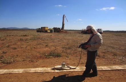
24 REQUIREMENTS FROM THE CLIENT FOR DATA ACQUISITION Requirement for Geo-Support: It is important to have a fully qualified and experienced geologist on site. Surface mapping will also augment the radar survey. Requirement for Casual Labour: Casual-labour clearance teams and manual pulling assistance is required. Larger antennas require more manpower. 1 man can pull a 6m antenna, 2 men for a 10 or 15m antenna. Requirement for a Surveyor with DGPS: A surveyor with a DGPS should be provided, as the Radar has real time reporting where structures are identified, real time marking can be achieved. 26

: Pictures of well cleared profile lines Above & Right: the device is pulled along well cleared profile lines.")
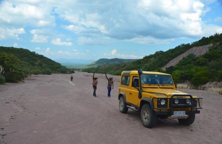
25 DATA ACQUISITION The antennas require to be flush with the surface highest performance achieved on machine prepared grids / lines. The use of 4x4 vehicles as the tow vehicle is the preferred approach but not essential with the 4 x 4 in low range travelling at a crawl 1km per hr The operator sets the radar to fire automated regular shots such as once every half second or one second. Fig 2 (Left): Pictures of well cleared profile lines Above & Right: the device is pulled along well cleared profile lines. The lightweight, highly portable system allows for rapid mobilization and deployment. The Radar is towed either by hand, behind a 4x4 or quad bike. 27


26 DATA ACQUISITION THE RADAR IN ACTION The spacing of the radar shots For small objects (pipes, cables, small voids etc.), shots may be taken along the profile is chosen taken every 20 cm to 30cm, for shallow geological surveys (e.g. according to the required scale of the alluvial deposits) spacing may be cm. target objects. 28

.")

27 DATA ACQUISTION - technical The radar can be set to automatic when dragged behind a 4x4 or quadbike. The timing of the shots depends on what mode the system is set to. Binary is quick (1 shot every half second), logarithmic delivers more detailed data and has a longer calculation time (one shot every second). Fig 3&4 (above): Recording of the EM wave, showing different parameters - binary is a quick method using just one pulse of energy, Logarithmic uses many pulses to determine more detail. 29

28 DATA ACQUISTION technical continued At each measurement point, the arrival time of the signal is recorded from the geological boundaries. The profile Radargram is formed in real time on the operators console LCD screen in the form of a binary plot depicting radar return time of the subsurface reflections. The EM wave travel times, depending on the reflector depth and propagation velocity, vary along the profile giving a picture of subsurface layered structure. Fig 5 (above): The operators console displays the wave form (right side) and the build up of the profile (left side) Experienced operators can therefore recognize features such as voids, as the EM wave travels faster in voids than in the surrounding material. 30
, are stored in the console memory, which can then be instantly downloaded into a normal laptop computer for instant review.")
 operator should be onhand, walking with the operator, to mark points of interest.")
29 DATA ACQUISTION technical continued Results of the survey, including the wave-forms for each point/ shot in the survey (every 10cm to 110cm depending on the objective), are stored in the console memory, which can then be instantly downloaded into a normal laptop computer for instant review. This real-time capability means that the operator can mark features of interest as the profile is taken. Therefore a Differential GPS (DGPS) operator should be onhand, walking with the operator, to mark points of interest. This allows the client to mark the features on his own software for subsequent actions to be accurately delivered (drilling etc.). 31

30 IDNETIFYING STRUCTURE & SHOT SPACING Vertical structure, we see this as the diagram below attempts to portray. We do see vertical structure quite well because we get the signal reflection not only from horizontal boundaries. Fig 6 (Left): Capturing Structural Detail The Radar operator can either manually operate the firing switch or it can be set to automatic. Shot spacing is determined by the clients objective, and the speed of the traverse. Where we have competent horizontal coal layers we may take a shot every 1.5m. Fig 7 (above): Shot spacing 32

31 ! ANALYSIS Above: A coal seam is shown over sandstone bedrock.! Data is collected and downloaded onto a laptop for analysis on proprietary software. Typically taking 12hrs to fully analyse 1km line of data. Preliminary analysis on the laptop can be conducted immediately in the field to check data quality and features of interest. The final report will be delivered no later than 21 days following the completion of data collection. 31
32 DATA ACQUISITION PRODUCTION & CALIBRATION Rate of Collection: We assume that by manual data collection, we will generate between 2.5km to 3.5km of line kilometres per day on land. A video example can be seen at (a) and (b) This is an arbitrary calculation, and when surveying for voids, it may be necessary to have a much greater shot concentration i.e. more shots over shorter distances, so that several shots pass through each void. Factors such as definition and detail required, size of target features, and antenna/transmitter arrays all define the speed. Adaptable Planning: As mentioned above, Lozar sees features in real time, and can instantly download data to obtain an initial analysis. Often the client will amend the profile plan due to Lozar s immediate ability to understand the geological conditions, or due to topographical/ vegetation obstructions. Liaison with the project geologist is essential, and mutual collaboration is required. Calibration: Where possible, the profiles should pass through a point of reference, such as an augur hole, or drill hole, where the stratigraphy and assay data is known, or perhaps from a visible feature like a pit-face, that enables the geo-electric signature in the radargram to be definitively identified. The sub-surface geoelectric signature can then be matched along the profile, and recognised in other profiles taken locally where there is no calibration point. 33
SURVEYING FOR GOLD. Page 1 of 25
 SURVEYING FOR GOLD Page 1 of 25 Page 2 of 25 Contents Introduction to Lozar Radar... 4 The Ground Penetrating Radar (GPR) system and Methodology... 4 Lozar Radar Surveying for Gold... 7 How Lozar Radar
GEOPHYSICAL SITE CHARACTERIZATION IN SUPPORT OF HIGHWAY EXPANSION PROJECT
 GEOPHYSICAL SITE CHARACTERIZATION IN SUPPORT OF HIGHWAY EXPANSION PROJECT * Shane Hickman, * Todd Lippincott, * Steve Cardimona, * Neil Anderson, and + Tim Newton * The University of Missouri-Rolla Department
SIXTH SCHEDULE REPUBLIC OF SOUTH SUDAN MINISTRY OF PETROLEUM, MINING THE MINING (MINERAL TITLE) REGULATIONS 2015
 REGULATIONS 2015") SIXTH SCHEDULE REPUBLIC OF SOUTH SUDAN MINISTRY OF PETROLEUM, MINING THE MINING ACT, 2012 THE MINING (MINERAL TITLE) REGULATIONS 2015 Guidelines should be prepared by the Directorate of Mineral Development
SIXTH SCHEDULE REPUBLIC OF SOUTH SUDAN MINISTRY OF PETROLEUM, MINING THE MINING ACT, 2012 THE MINING (MINERAL TITLE) REGULATIONS 2015 Guidelines should be prepared by the Directorate of Mineral Development
Lima Project: Seismic Refraction and Resistivity Survey. Alten du Plessis Global Geophysical
 Lima Project: Seismic Refraction and Resistivity Survey Alten du Plessis Global Geophysical Report no 0706/2006 18 December 2006 Lima Project: Seismic Refraction and Resistivity Survey by Alten du Plessis
Common Exploration Methods.
 Common Exploration Methods. The following list contains the most common methods which a company with a mineral prospecting licence in Northern Ireland might use to carry out a mineral prospecting programme.
Application of Ground Penetrating Radar for hydro-geological study
 Journal of Scientific & Industrial Research Vol. 65, February 2006, pp. 160-164 Application of Ground Penetrating Radar for hydro-geological study K K K Singh* Central Mining Research Institute, Dhanbad
In-seam GPR and 2-C seismic investigations at the Goderich, Ontario salt mine
 In-seam GPR and 2-C seismic investigations at the Goderich, Ontario salt mine Jill Belisle and Robert R. Stewart In-seam techniques ABSTRACT In-seam GPR and 2-C seismic techniques used in conjunction with
Use of Geophysical Software for Interpretation of Ice-Penetrating Radar Data and Mapping of Polar Ice Sheets
 Use of Geophysical Software for Interpretation of Ice-Penetrating Radar Data and Mapping of Polar Ice Sheets Alex O. Martinez University of Kansas 2335 Irving Hill Road Lawrence, KS 66045-7612 http://cresis.ku.edu
Early Exploration Plan Activity Information
 Early Exploration Plan Activity Information Activities That Require an Early Exploration Plan: Line cutting that is a width of 1.5 metres or less; Geophysical surveys on the ground requiring the use of
Scout Aerial Africa DRONES THE BIG PICTURE FOR GEOLOGY AND MINING
 Scout Aerial Africa DRONES THE BIG PICTURE FOR GEOLOGY AND MINING WHO ARE WE? Scout Aerial Group is a diversified operating and investment group with market leading businesses and targeted investment in
GROUND ACOUSTIC PENETRATION
 GROUND ACOUSTIC PENETRATION Bronislav A. Koulmametiev and Boris V. Matveev InterGeoRAP Consulting. 8 Hartleap Lane, Beldon, WA 6027. E-mail: tchern@iinet.net.au 1. DESCRIPTION Ground Acoustic Penetration
MOUNT POLLEY MINING CORPORATION TECHNICAL REPORT ON MULTI-ELECTRODE RESISTIVITY AND SEISMIC REFRACTION SURVEYS MOUNT POLLEY TAILINGS DAM PROJECT
 MOUNT PLEY MINING CORPORATION TECHNICAL REPORT ON MULTI-ELECTRODE RESISTIVITY AND SEISMIC REFRACTION SURVEYS MOUNT PLEY TAILINGS DAM PROJECT LIKELY, B.C. by Claudia Krumbiegel, M.Sc. Cliff Candy, P.Geo.
Geologging Imagery, Applications and Geological Interpretation. Shea Altadonna 1, Jim Fulton 2, E.I.T.
 Geologging Imagery, Applications and Geological Interpretation Shea Altadonna 1, Jim Fulton 2, E.I.T. 1 Geologist, Advanced Construction Techniques Inc. 1000 N. West St. Ste 1200, Wilmington, DE 19801;
MT Prospecting. Map Resistivity. Determine Formations. Determine Structure. Targeted Drilling
 MT Prospecting Map Resistivity Determine Formations Determine Structure Targeted Drilling Cross-sectional interpretation before and after an MT survey of a mineral exploration prospect containing volcanic
High Resolution Geophysics: A Better View of the Subsurface. By John Jansen, P.G., Ph.D., Aquifer Science and Technology
 High Resolution Geophysics: A Better View of the Subsurface By John Jansen, P.G., Ph.D., Aquifer Science and Technology Geologist Use Only Part of the Information Available To Them Most Geologist rely
LOGGING AND SAMPLING PROTOCOL
 LOGGING AND SAMPLING PROTOCOL The following discussion will address a number of issues including; the physical taking of the samples, geological descriptions, sample numbering and handling, and the dispatch
Seismic Velocity Measurements at Expanded Seismic Network Sites
 UK/KRCEE Doc #: P8.3 2005 Seismic Velocity Measurements at Expanded Seismic Network Sites Prepared by Kentucky Research Consortium for Energy and Environment 233 Mining and Minerals Building University
Foundation pile and cavity detection by the 3D directional borehole radar system, ReflexTracker
 Foundation pile and cavity detection by the 3D directional borehole radar system, ReflexTracker K. Wada, S. Karasawa, K. Kawata, T. Ueki Matsunaga Geo-survey Co., Ltd. 1-23-1 Ooi, 140-0014, Tokyo, Japan
Geophysics for Environmental and Geotechnical Applications
 Geophysics for Environmental and Geotechnical Applications Dr. Katherine Grote University of Wisconsin Eau Claire Why Use Geophysics? Improve the quality of site characterization (higher resolution and
Engineering Geophysical Application to Mine Subsidence Risk Assessment
 Engineering Geophysical Application to Mine Subsidence Risk Assessment By: Kanaan Hanna, Sr. Mining Engineer Steve Hodges, Sr. Geophysicist Jim Pfeiffer, Sr. Geophysicist Dr. Keith Heasley, Professor West
Making the Most out of Downhole Geophysics. Travis Pastachak, P.Geo, PMP
 Making the Most out of Downhole Geophysics 25 06 2015 Travis Pastachak, P.Geo, PMP Agenda 1. Who are we? 2. Who am I? 3. Introduction to Downhole Geophysical Tools 4. Primary Uses 5. Unconventional Uses
GPR surveys at Nõmmküla Detection of underground water routes
 GPR surveys at Nõmmküla 2009 Detection of underground water routes Tomi Herronen & Timo Saarenketo 2009 1. Introduction The purpose of this survey was to locate possible underground water routes (rivers)
Our Services. What We Do. How We Can Help. Contact us today: January (0)
") Listening and Understanding to Optimize our Efficiency Our Experience and Knowledge to Work for You Tailor-made Solutions to Meet your Needs Our Challenge is You Success What We Do Our Services GeoViz
Listening and Understanding to Optimize our Efficiency Our Experience and Knowledge to Work for You Tailor-made Solutions to Meet your Needs Our Challenge is You Success What We Do Our Services GeoViz
MASW AND GPR SURVEY TO DELINEATE DEPTH-TO- BEDROCK AND CRYSTAL CAVITIES FOR MINERAL EXPLORATION, HIDDENITE, NORTH CAROLINA.
 MASW AND GPR SURVEY TO DELINEATE DEPTH-TO- BEDROCK AND CRYSTAL CAVITIES FOR MINERAL EXPLORATION, HIDDENITE, NORTH CAROLINA Mario Carnevale, Hager GeoScience, Inc., Woburn, MA Jutta Hager, Hager GeoScience,
Ronin and Dayton Placer Ground-penetrating Radar Survey Report
 Ronin and Dayton Placer Ground-penetrating Radar Survey Report Tenures: 837095, 837097, 889865, 890187 Mining Division: Greenwood NTS Location: 082E/03 Geographic Center Coordinates: UTM Zone 11, E 345340,
Comparison of geophysical. techniques to determine depth to. bedrock in complex weathered. environments of the Mount Crawford. region, South Australia
 Comparison of geophysical techniques to determine depth to bedrock in complex weathered environments of the Mount Crawford region, South Australia Thesis submitted in accordance with the requirements of
Guidelines for the Form of Reports and Illustrations
 Guidelines for the Form of Reports and Illustrations as Prescribed by the Minister as per Section 55(2) of The Consolidated Newfoundland and Labrador Regulation 1143/96 (As Amended) (Revised - December,
Geophysical Investigation of a 19th Century Archeological Site, Boston College K. Corcoran, J. Hager, M. Carnevale
 Geophysical Investigation of a 19th Century Archeological Site, Boston College K. Corcoran, J. Hager, M. Carnevale Hager GeoScience, Inc., Waltham, MA ------------------------------------------------------------------------
FloatSeis Technologies for Ultra-Deep Imaging Seismic Surveys
 FloatSeis Technologies for Ultra-Deep Imaging Seismic Surveys 25 th January, 2018 Aleksandr Nikitin a.nikitin@gwl-geo.com Geology Without Limits Overview 2011-2016 GWL Acquired over 43000 km 2D seismic
Evaluation of Geological Conditions Ahead of Tunnel Face Using Seismic Tomography between Tunnel and Surface
 Evaluation of Geological Conditions Ahead of Tunnel Face Using Seismic Tomography between Tunnel and Surface Y. Yokota a *, T. Ymamoto a and K. Kurihara a a Kajima Technical Research Institute, 19-1, Tobitakyu
SEISMIC SURVEYS FOR IMAGING THE REGOLITH
 SEISMIC SURVEYS FOR IMAGING THE REGOLITH Barry Drummond Geoscience Australia. PO Box 378, Canberra, ACT 2601. E-mail: barry.drummond@ga.gov.au 1. INTRODUCTION Seismic reflection and refraction imaging
First results confirm new areas with potential for further high grade NdPr mineralisation
 10 September 2018 First results confirm new areas with potential for further high grade NdPr mineralisation Rift Valley Resources Limited ( Company ) (ASX: RVY) is pleased to report the results of recently
CONTENTS 1. INTRODUCTION. 2. THE D.C. RESISTIVITY METHOD 2.1 Equipment 2.2 Survey Procedure 2.3 Data Reduction
 (i) CONTENTS 1. INTRODUCTION page 1 2. THE D.C. RESISTIVITY METHOD 2.1 Equipment 2.2 Survey Procedure 2.3 Data Reduction 3 3 3 3 3. GEOPHYSICAL RESULTS 3.1 General 3.2 Discussion 4 4 4 4. LIMITATIONS 5
Robotic Site Survey for ISRU
 NASA Ames Research Center Maria Bualat Intelligent Robotics Group Maria.Bualat@nasa.gov Outline Site Survey Overview GPR Survey Hydrogen Prospecting 2 Human-Robot Site Survey Project Systematic survey
Case Study: University of Connecticut (UConn) Landfill
 Landfill") Case Study: University of Connecticut (UConn) Landfill Problem Statement:» Locate disposal trenches» Identify geologic features and distinguish them from leachate and locate preferential pathways in fractured
Case Study: University of Connecticut (UConn) Landfill Problem Statement:» Locate disposal trenches» Identify geologic features and distinguish them from leachate and locate preferential pathways in fractured
VMS-GeoMil. Background
 Background When using a drilling rig for cone penetration testing, a mechanical clamp can be mounted to the drilling head (by means of a special transition piece). The depth than can be achieved depends
Petroleum Exploration
 Petroleum Exploration Upstream Petroleum Exploration The role of exploration is to provide the information required to exploit the best opportunities presented in the choice of areas, and to manage research
GPR AS A COST EFFECTIVE BEDROCK MAPPING TOOL FOR LARGE AREAS. Abstract
 GPR AS A COST EFFECTIVE BEDROCK MAPPING TOOL FOR LARGE AREAS Dr. Jutta L. Hager, Hager GeoScience, Inc., Waltham, MA Mario Carnevale, Hager GeoScience, Inc., Waltham, MA Abstract Hager GeoScience, Inc.
P Forsmark site investigation. Ground penetrating radar and resistivity measurements for overburden investigations
 P-03-43 Forsmark site investigation Ground penetrating radar and resistivity measurements for overburden investigations Johan Nissen, Malå Geoscience AB April 2003 Svensk Kärnbränslehantering AB Swedish
3-D ground-penetrating radar surveys on a frozen river lagoon
 3-D ground-penetrating radar surveys on a frozen river lagoon Monica Moldoveanu and Robert R. tewart ABTRACT Ground-penetrating radar (GPR) surveys were acquired at Bowness Park, Calgary to characterize
SESE MEASURED RESOURCE EXCEEDS 650MT COAL
 For electronic distribution 15 th August 2012 SESE MEASURED RESOURCE EXCEEDS 650MT COAL Highlights: Initial Measured Resource at Sese calculated at 651Mt coal. Sese Coal & Power Project: Resource Summary
Seismic tests at Southern Ute Nation coal fire site
 Seismic tests at Southern Ute Nation coal fire site Sjoerd de Ridder and Seth S. Haines ABSTRACT We conducted a near surface seismic test at the Southern Ute Nation coal fire site near Durango, CO. The
Geophysical Site Investigation (Seismic methods) Amit Prashant Indian Institute of Technology Gandhinagar
 Amit Prashant Indian Institute of Technology Gandhinagar") Geophysical Site Investigation (Seismic methods) Amit Prashant Indian Institute of Technology Gandhinagar Short Course on Geotechnical Aspects of Earthquake Engineering 04 08 March, 2013 Seismic Waves
Geophysical Site Investigation (Seismic methods) Amit Prashant Indian Institute of Technology Gandhinagar Short Course on Geotechnical Aspects of Earthquake Engineering 04 08 March, 2013 Seismic Waves
Applied Geophysics for Environmental Site Characterization and Remediation
 Applied Geophysics for Environmental Site Characterization and Remediation MSECA Webinar September 24, 2015 John Mundell, P.E., L.P.G. Ryan Brumbaugh, L.P.G. MUNDELL & ASSOCIATES, INC. Webinar Objective
5 Further Case Histories
 5 Further Case Histories Chapter outline Cavity/old workings detection Detailed pillar detection Near-surface cavity detection Dyke, sill and fault detection In-seam disruptions (lenses, etc.) Coal thickness
Site Characterization & Hydrogeophysics
 Site Characterization & Hydrogeophysics (Source: Matthew Becker, California State University) Site Characterization Definition: quantitative description of the hydraulic, geologic, and chemical properties
TATA CHEMICALS MAGADI LIMITED (Mining Section) TRONA CRUSHING PLANT AND PREWASH TANK FACILITY PROJECT
 TRONA CRUSHING PLANT AND PREWASH TANK FACILITY PROJECT") 1 TATA CHEMICALS MAGADI LIMITED (Mining Section) TRONA CRUSHING PLANT AND PREWASH TANK FACILITY PROJECT RFQ for Geotechnical Investigations and Foundation Recommendations TCML/MS/RFQ1/2017 October 2017
1 TATA CHEMICALS MAGADI LIMITED (Mining Section) TRONA CRUSHING PLANT AND PREWASH TANK FACILITY PROJECT RFQ for Geotechnical Investigations and Foundation Recommendations TCML/MS/RFQ1/2017 October 2017
Demonstration of the Advanced Radio Imaging Method (RIM): Ground Truth Results for Three-Dimensional Imaging of Coal Seams
: Ground Truth Results for Three-Dimensional Imaging of Coal Seams") Demonstration of the Advanced Radio Imaging Method (RIM): Ground Truth Results for Three-Dimensional Imaging of Coal Seams Joseph Duncan, RIM Geophysicist Larry G. Stolarczyk, President Stolar Horizon,
Demonstration of the Advanced Radio Imaging Method (RIM): Ground Truth Results for Three-Dimensional Imaging of Coal Seams Joseph Duncan, RIM Geophysicist Larry G. Stolarczyk, President Stolar Horizon,
For personal use only
 (ASX:OUM) QUARTERLY ACTIVITIES REPORT PERIOD ENDING 30 SEPTEMBER 2011 MT WELLS HIGHLIGHTS IDENTIFICATION OF A FURTHER 1KM OF EXTENSIONAL POTENTIAL IN ADDITION TO THE 1KM OF KNOWN TIN/COPPER MINERALISATION.
TECHNICAL STUDIES. rpsgroup.com/energy
 TECHNICAL STUDIES RPS Energy - a global energy consultancy RPS Energy is part of the RPS Group plc, a FTSE 250 company with an annual turnover of $700m and over 4700 employees. As one of the world s leading
Enhanced Subsurface Interpolation by Geological Cross-Sections by SangGi Hwang, PaiChai University, Korea
 Enhanced Subsurface Interpolation by Geological Cross-Sections by SangGi Hwang, PaiChai University, Korea Abstract Subsurface geological structures, such as bedding, fault planes and ore body, are disturbed
Geophysical Exploration in Water Resources Assessment. John Mundell, P.E., L.P.G., P.G. Ryan Brumbaugh, L.P.G. Mundell & Associates, Inc.
 Geophysical Exploration in Water Resources Assessment John Mundell, P.E., L.P.G., P.G. Ryan Brumbaugh, L.P.G. Mundell & Associates, Inc. Presentation Objective Introduce the use of geophysical survey methods
POTASH DRAGON CHILE GEOPHYSICAL SURVEY TRANSIENT ELECTROMAGNETIC (TEM) METHOD. LLAMARA and SOLIDA PROJECTS SALAR DE LLAMARA, IQUIQUE, REGION I, CHILE
 METHOD. LLAMARA and SOLIDA PROJECTS SALAR DE LLAMARA, IQUIQUE, REGION I, CHILE") POTASH DRAGON CHILE GEOPHYSICAL SURVEY TRANSIENT ELECTROMAGNETIC (TEM) METHOD LLAMARA and SOLIDA PROJECTS SALAR DE LLAMARA, IQUIQUE, REGION I, CHILE OCTOBER 2012 CONTENT Page I INTRODUCTION 1 II FIELD
POTASH DRAGON CHILE GEOPHYSICAL SURVEY TRANSIENT ELECTROMAGNETIC (TEM) METHOD LLAMARA and SOLIDA PROJECTS SALAR DE LLAMARA, IQUIQUE, REGION I, CHILE OCTOBER 2012 CONTENT Page I INTRODUCTION 1 II FIELD
Advanced Technologies in digital 3D-Surface, -Deposit und -Mine- Modelling
 8 th Jordanien International Mining Conference 19.09. to 21.09.2017 Ammann - Jordan Natural Resources: Projected Investment, Reality and Aspirations Dr.-Ing. Marc Dohmen, Aachen Dohmen, Herzog & Partner
Geophysical Survey Report
 Report Stanley Bank Slitting Mill St Helens, Merseyside for St Helens Council November 2006 J2251 Hannah Heard BSc (Hons) AIFA Document Title: Client: Stratascan Job No: Techniques: Report Stanley Bank
Short Note 3D modeling of subsurface utilities using Ground Penetrating Radar (GPR) data
 data") 217 Short Note 3D modeling of subsurface utilities using Ground Penetrating Radar GPR data Arnab Dutta and Sameer Saran Geoinformatics Department, Indian Institute of Remote Sensing, ISRO, Dehradun, India
217 Short Note 3D modeling of subsurface utilities using Ground Penetrating Radar GPR data Arnab Dutta and Sameer Saran Geoinformatics Department, Indian Institute of Remote Sensing, ISRO, Dehradun, India
Geophysical Survey Report
 Report Lost Mansion of Nydfwch, Penllergare, Swansea for January 2008 J2449 John Cook BSc. (Hons) Document Title: Client: Stratascan Job No: Techniques: Report Lost Mansion of Nydfwch, Penllergare, Swansea
Instructional Objectives
 GE 6477 DISCONTINUOUS ROCK 8. Fracture Detection Dr. Norbert H. Maerz Missouri University of Science and Technology (573) 341-6714 norbert@mst.edu Instructional Objectives 1. List the advantages and disadvantages
Near-Surface Seismic Reflection Applications
 Near-Surface Seismic Reflection Applications Don Steeples, The University of Kansas, Lawrence, KS USA Abstract Nonintrusive methods of gaining knowledge about the Earth s subsurface comprise several of
Early Exploration Permit Activity Information
 Early Exploration Permit Activity Information Activities That Require an Early Exploration Permit: Line cutting that is a width greater than 1.5 metres Mechanized stripping of a total surface area of greater
Module 1 : Site Exploration and Geotechnical Investigation
 Objectives In this section you will learn the following Displacement borings Wash boring Auger boring Rotary drilling Percussion drilling Continuous sampling Boring methods of exploration The boring methods
In Association With. Introduces. TPT Contractor
 In Association With Introduces TPT Contractor Software for Contractors with TENSIONMETERS Table of Contents Capabilities 4 Setup and Use 7 The Dashboard 12 Tower Setup Form 18 Field Calibration Verification
Drillworks. DecisionSpace Geomechanics DATA SHEET
 DATA SHEET Drillworks overview DecisionSpace Geomechanics Key features Pre-drill, real-time, and post-drill analyses are all easily performed in one application using the latest data from across the field
Geophysical Methods for Screening and Investigating Utility Waste Landfill Sites in Karst Terrain
 Geophysical Methods for Screening and Investigating Utility Waste Landfill Sites in Karst Terrain Gary Pendergrass, PE, RG, F.NSPE Principal Geological Engineer Kansas City Geotechnical Conference 2017
Ronin Placer Ground-penetrating Radar Survey Report
 Ronin Placer Ground-penetrating Radar Survey Report Tenures: 837095, 837097 Mining Division: Greenwood NTS Location: 082E/03 Geographic Center Coordinates: UTM Zone 11, E 345340, N 5438730 Claims Owner:
FINAL REPORT GEOPHYSICAL INVESTIGATION WATER TOWER NO. 6 SITE PLANT CITY, FL
 APPENDIX B FINAL REPORT GEOPHYSICAL INVESTIGATION WATER TOWER NO. 6 SITE PLANT CITY, FL Prepared for Madrid Engineering Group, Inc. Bartow, FL Prepared by GeoView, Inc. St. Petersburg, FL February 28,
FUNDAMENTALS OF SEISMIC EXPLORATION FOR HYDROCARBON
 FUNDAMENTALS OF SEISMIC EXPLORATION FOR HYDROCARBON Instructor : Kumar Ramachandran 10 14 July 2017 Jakarta The course is aimed at teaching the physical concepts involved in the application of seismic
Cross-well seismic modelling for coal seam delineation
 P-134 Sanjeev Rajput, CSIRO, P. Prasada Rao*, N. K. Thakur, NGRI Summary Finite-difference analyses is attempted to simulate a multi layered complex coal seam model in order to differentiate top and bottom
Frequently Asked Questions
 Frequently Asked Questions 1 Is THERMOVISION TOMOGRAPHY technology independent, or it requires previous seismic or other data? THERMOVISION TOMOGRAPHY technology is a stand-alone technology. Independent
Geotechnical verification of impact compaction
 PII-73 Geotechnical verification of impact compaction P. J. Waddell1, R. A. Moyle2 & R. J. Whiteley1 1 2 Coffey Geotechnics, Sydney, Australia Coffey Geotechnics, Harrogate, UK Abstract Remediation of
Innovations in Airborne Exploration Geophysics. Benedikt Steiner
 Innovations in Airborne Exploration Geophysics Benedikt Steiner What is exploration geophysics? 2 The use of the Earth s physical properties in locating geological features of interest to mining. Magnetics,
Coal Loss and Dilution Considerations for Western Canadian Foothills Open Pit Coal Projects
 Coal Loss and Dilution Considerations for Western Canadian Foothills Open Pit Coal Projects Presenter: Mike Allen Manager, Surface Mining April 29, 2015 Outline Terms / Definitions Factors affecting coal
T: E:
 PAS 128 UTILITY DETECTION AND MAPPING TOPOGRAPHICAL SURVEYS UTILITY RECORD SEARCHES AND DESK TOP STUDY SURFACE WATER DRAINAGE SURVEYS GROUND CLEARANCE SURVEYS MEASURED BUILDING SURVEYS LASER SCANNING UAV
Project Report ABRIDGED VERSION
 Project Report N PR-HF-09-01 ABRIDGED VERSION Logbaba Survey Cameroon Operated by Geodynamics Research S.r.l -Trento -Italy in November-Dicember 2009 Abridged Version Compiled in LATEX: May 5, 2010 Project
ATON ANNOUNCES THE RESULTS OF THE RECENT DEEP PENETRATING GPR SURVEY AT THE ABU MARAWAT CONCESSION
 FOR IMMEDIATE RELEASE: ATON ANNOUNCES THE RESULTS OF THE RECENT DEEP PENETRATING GPR SURVEY AT THE ABU MARAWAT CONCESSION Vancouver, March 21, 2018: Aton Resources Inc. (AAN: TSX-V) ( Aton or the Company")
CHALLENGES WITH FOREIGN DATA FORMATS & GEOLOGICAL CONFIDENCE
 CHALLENGES WITH FOREIGN DATA FORMATS & GEOLOGICAL CONFIDENCE Some Case Study Examples from Russia and Central Asia Grant van Heerden, Pr.Sci.Nat. Nick Ryan, CP(Geo) PRESENTATION OVERVIEW The Concept of
GIS Workshop Data Collection Techniques
 GIS Workshop Data Collection Techniques NOFNEC Conference 2016 Presented by: Matawa First Nations Management Jennifer Duncan and Charlene Wagenaar, Geomatics Technicians, Four Rivers Department QA #: FRG
APPENDIX C GEOPHYSICAL REPORT
 APPENDIX C GEOPHYSICAL REPORT GEOPHYSICAL ENGINEERING SURVEY REPORT 700 E 241 st Street NOVA PROJECT NUMBER 15-0522 DATED January 27, 2015 PREPARED FOR: LANGAN Long Warf Maritime Center New Haven, CT 06511
THE USE OF GEOMATICS IN CULTURAL HERITAGE AND ARCHAEOLOGY FOR VARIOUS PURPOSES
 THE USE OF GEOMATICS IN CULTURAL HERITAGE AND ARCHAEOLOGY FOR VARIOUS PURPOSES FEBRUARY 2013 AL BEIDA GEOPLAN CONTENT Company Profile Concept Objectives and Strategies Data Production Methods Data Samples
POTENTIAL USE OF GROUND PENETRATING RADAR IN HIGHWAY ROCK CUT STABILITY Norbert H. Maerz* and Wooyoung Kim^ ABSTRACT INTRODUCTION
 Geophysics 2000, Dec. 11-15, 2000, St. Louis, MO, 9 pp. POTENTIAL USE OF GROUND PENETRATING RADAR IN HIGHWAY ROCK CUT STABILITY Norbert H. Maerz* and Wooyoung Kim^ *Rock Mechanics and Explosives Research
GEOL4714 Final Exam Fall 2005, C. H. Jones instructor
 GEOL4714 Final Exam Fall 2005 p. 1 GEOL4714 Final Exam Fall 2005, C. H. Jones instructor Name: Student ID #: Feel free to use the back of the sheets for answers needing more space. (1) (10 pts) For each
Introduction to Ground Penetrating Radar. and its General Use Applied to. Fault Investigation
 Introduction to Ground Penetrating Radar and its General Use Applied to Fault Investigation Arik Arnevik University of Wisconsin: Eau Claire - Geography 368 Table of Contents Page Number Abstract.....1
SEISMIC INVESTIGATION OF UNDERGROUND COAL FIRES; A FEASIBILITY STUDY AT THE SOUTHERN UTE NATION COAL FIRE SITE, DURANGO, COLORADO.
 SEISMIC INVESTIGATION OF UNDERGROUND COAL FIRES; A FEASIBILITY STUDY AT THE SOUTHERN UTE NATION COAL FIRE SITE, DURANGO, COLORADO Sjoerd de Ridder, Department of Geophysics, Stanford University. Nigel
Mandatory Assignment 2013 INF-GEO4310
 Mandatory Assignment 2013 INF-GEO4310 Deadline for submission: 12-Nov-2013 e-mail the answers in one pdf file to vikashp@ifi.uio.no Part I: Multiple choice questions Multiple choice geometrical optics
Understanding the Causes of Roof Control Problems on A Longwall Face from Shield Monitoring Data - a Case Study
 University of Wollongong Research Online Coal Operators' Conference Faculty of Engineering and Information Sciences 2011 Understanding the Causes of Roof Control Problems on A Longwall Face from Shield
Resistivity survey at Stora Uppåkra, Sweden
 Resistivity survey at Stora Uppåkra, Sweden Dahlin, Torleif Published in: Uppåkra - Centrum i analys och rapport 2001 Link to publication Citation for published version (APA): Dahlin, T. (2001). Resistivity
COMPLETION OF PHASE 1 DRILLING AT TITIRIBI PROJECT IDENTIFIES ADDITIONAL SIGNIFICANT COAL INTERCEPTS
 Perth Office 512 Hay Street Subiaco, WA, 6008 T: +61 8 9381 4534 F: +61 8 9380 6440 E: admin@ascotresources.com W: www.ascotresources.com ASX ANNOUNCEMENT 4 June 2013 The Manager Company Announcements
Subsurface laser scanning and multibeam sonar void surveys What really does lie beneath and where exactly? Mitigating your Risk
 Subsurface laser scanning and multibeam sonar void surveys What really does lie beneath and where exactly? Mitigating your Risk UNDERGROUND CAVITY SURVEYS C-ALS (Cavity Auto Laser Scanner) - DRY Deployed
GEOTECHNICAL ENGINEERING II. Subject Code : 06CV64 Internal Assessment Marks : 25 PART A UNIT 1
 GEOTECHNICAL ENGINEERING II Subject Code : 06CV64 Internal Assessment Marks : 25 PART A UNIT 1 1. SUBSURFACE EXPLORATION 1.1 Importance, Exploration Program 1.2 Methods of exploration, Boring, Sounding
We N Geophysical Near-surface Characterization for Static Corrections: Multi-physics Survey in Reggane Field, Algeria
 We N114 01 Geophysical Near-surface Characterization for Static Corrections: Multi-physics Survey in Reggane Field, Algeria A. Pineda* (Repsol), S. Gallo (CGG) & H. Harkas (GRN Sonatrach) SUMMARY We are
GPR imaging of the internal structure of modern migrating dunes, Napeague, NY
 GPR imaging of the internal structure of modern migrating dunes, Napeague, NY James D. Girardi and Dan M. Davis, Dept. of Geosciences, SUNY Stony Stony Brook INTRODUCTION By using ground penetrating radar
Georadar and geoelectricity method to identify the determine zone of sliding landslide
 IOP Conference Series: Earth and Environmental Science PAPER OPEN ACCESS Georadar and geoelectricity method to identify the determine zone of sliding landslide To cite this article: Y K Dalimunthe and
APPLICATIONS OF SEISMIC REFLECTION IN THE COAL ENVIRONMENT. Troy Peters and Natasha Hendrick. Velseis Pty Ltd, PO Box 118, Sumner Park, Qld 4074
 ALICATIONS OF SEISMIC REFLECTION IN THE COAL ENVIRONMENT Troy eters and Natasha Hendrick Velseis ty Ltd, O Box 118, Sumner ark, Qld 4074 ABSTRACT Seismic reflection has grown to become a valuable geophysical
C13^COMMONWEALTH OF AUSTRALIA
 tal C13^COMMONWEALTH OF AUSTRALIA DEPARTMENT OF NATIONAL DEVELOPMENT BUREAU OF MINERAL RESOURCES, GEOLOGY AND GEOPHYSICS 44 1 NE/41 RECORD No. 1963/22 l^' it Ril R y#11, 1 zz^g M^ P3 C3 rn 00 GEOPHYSICAL
For personal use only
 ASX:LEG 10 July 2014 Fraser Range Aeromagnetic Survey Identifies Targets Seven priority targets considered prospective for nickel-copper Targets interpreted to relate to intrusive mafic/ultramafic bodies
Seismic Data Acquisition In Complex Boulder Bed Area: A Case Study In Arunachal Pradesh, North East INDIA
 P-206 Seismic Data Acquisition In Complex Boulder Bed Area: A Case Study In Arunachal Pradesh, North East INDIA Summary G.K.Ghosh*, D. N. Saroj, A.K.Khanna and R. Das gupta, Oil India Limited The area
VELA. Getting started with the VELA Versatile Laboratory Aid. Paul Vernon
 VELA Getting started with the VELA Versatile Laboratory Aid Paul Vernon Contents Preface... 3 Setting up and using VELA... 4 Introduction... 4 Setting VELA up... 5 Programming VELA... 6 Uses of the Programs...
GOLDPLAY OUTLINES FIVE NEW EXPLORATION TARGETS AT THE SAN MARCIAL PROJECT IN MEXICO
 January 18, 2019 GOLDPLAY OUTLINES FIVE NEW EXPLORATION TARGETS AT THE SAN MARCIAL PROJECT IN MEXICO Vancouver, BC - Goldplay Exploration Ltd. (TSXV: GPLY, FRANKFURT: GPE, OTCQB: GLYXF) ( Goldplay or the
EXTREMELY FAST IP USED TO DELINEATE BURIED LANDFILLS. Norman R. Carlson, Cris Mauldin Mayerle, and Kenneth L. Zonge
 EXTREMELY FAST IP USED TO DELINEATE BURIED LANDFILLS Norman R. Carlson, Cris Mauldin Mayerle, and Kenneth L. Zonge Zonge Engineering and Research Organization, Inc. 3322 East Fort Lowell Road Tucson, Arizona,
PHASE 1 STUDIES UPDATE EROSION WORKING GROUP
 PHASE 1 STUDIES UPDATE EROSION WORKING GROUP Presented By MICHAEL WOLFF, PG Erosion Study Area Manager West Valley Demonstration Project Quarterly Public Meeting February 24, 2016 OUTLINE Study 1 Terrain