FINAL REPORT GEOPHYSICAL INVESTIGATION WATER TOWER NO. 6 SITE PLANT CITY, FL
|
|
|
- Nickolas Potter
- 5 years ago
- Views:
Transcription
1 APPENDIX B
2 FINAL REPORT GEOPHYSICAL INVESTIGATION WATER TOWER NO. 6 SITE PLANT CITY, FL Prepared for Madrid Engineering Group, Inc. Bartow, FL Prepared by GeoView, Inc. St. Petersburg, FL
3 February 28, 2010 Mr. Larry Madrid, P.E. Madrid Engineering Group, Inc. P.O. Box 2506 Bartow, FL Subject: Transmittal of Final Report for Geophysical Investigation Water Tower No. 6 Site Phase 2- Plant City, FL GeoView Project Number 8123 Dear Mr. Madrid, GeoView, Inc. (GeoView) is pleased to submit the final report that summarizes and presents the results of the geophysical investigation conducted at the Tank No. 6 Site. Ground penetrating radar and seismic reflection were used to evaluate near-surface geological conditions. GeoView appreciates the opportunity to have assisted you on this project. If you have any questions or comments about the report, please contact us. GEOVIEW, INC. Michael J. Wightman, P.G. President Florida Professional Geologist Number 1423 Chris Taylor, P.G. Vice President Florida Professional Geologist Number 2256 A Geophysical Services Company 4610 Central Avenue Tel.: (727) St. Petersburg, FL Fax: (727)
4 Page Introduction The site was located along National Guard Drive in Plant City, Florida. Prior to the geophysical investigation, two surface depressions had formed north of Water Tank No. 6. The first depression was approximately 40 feet (ft) in diameter, 2 ft deep and located approximately 70 ft north of the water tank. The second depression was approximately 10 ft in diameter, 3 ft deep and located approximately 160 ft north of the water tank. A prior geophysical investigation utilizing ground penetrating radar (GPR) was conducted in January 2010 (GeoView Final Report Number 7837). For this investigation the area for the GPR survey was expanded, but also included an area from the previous survey. In addition, a high-resolution seismic reflection survey was performed. The purpose of the geophysical investigation was to help characterize near-surface geological conditions around the water tower and to identify subsurface features that may be associated with sinkhole activity. The location of the geophysical survey area is provided on Figure 1. The investigation was conducted on February 14 and 15, A discussion of the field methods used to generate the report figures is provided in Appendix A Description of Geophysical Investigation 2.1 Ground Penetrating Radar Survey A GPR survey was conducted around within the fenced enclosure of the water tower area and to the east and west of the fenced enclosure. The GPR survey was conducted along a series of perpendicular transects spaced approximately 10 ft apart. The GPR data was collected with a Mala radar system. The GPR settings used for the survey are presented in Table 1. Table 1 GPR Equipment Settings Used for Exterior and Interior GPR Surveys Location Antenna Frequency Time Range (nano-seconds) Estimated Depth of GPR Signal Penetration Exterior 250 MHz 1/ to 30 ft bls 1/ MHz means mega-hertz and is the mid-range operating frequency of the GPR antenna. 2.1 Seismic Reflection Survey The seismic survey was conducted along four transect lines. The locations of the lines are shown as Line 1, Line 2, Line 3 and Line 4 on Figure 1. Data acquisition was accomplished using a Geometrics Geode, 48-channel seismograph
5 Page 2 system. Geoview acquired compression- (P-) wave seismic reflection data using a basic 48-geophone spread. The geophones were placed in a line with 5-foot spacing between each of the geophones. Shot points were performed at 5-foot intervals along each of the transects. The energy source used at each shot point consisted of a steel plate being struck by a 12-pound sledgehammer. Each shot point consisted of multiple hammer blows in an attempt to maximize the desired signal while minimizing background noise. A total of 225 shot points were recorded during the survey A description of the geophysical techniques and the methods employed for geological characterization studies is provided in Appendix A Identification of Possible Sinkhole Features The features observed on that are most commonly associated with sinkhole activity are: A downwarping of reflector sets, that are associated with suspected lithological contacts, toward a common center. Such features typically have with a bowl or funnel shaped configuration and can be associated with a deflection of overlying sediment horizons caused by the migration of sediments into voids in the underlying limestone. If the GPR reflector sets are sharply downwarping and intersect, they can create bow-tie shaped GPR reflection feature, which often designates the apparent center of the GPR anomaly. A localized significant increase in the depth of the penetration and/or amplitude of the GPR signal response. The increase in GPR signal penetration depth or amplitude is often associated with either a localized increase in sand content at depth or decrease in soil density. An apparent discontinuity in reflector sets, that are associated with suspected lithological contacts. The apparent discontinuities and/or disruption of the reflector sets may be associated with the downward migration sediments. The greater the severity of these features or a combination of these features the greater the likelihood that the identified feature is a sinkhole. It is not possible based on the geophysical data alone to determine if an identified feature is a sinkhole or, more importantly, whether that feature is an active sinkhole.
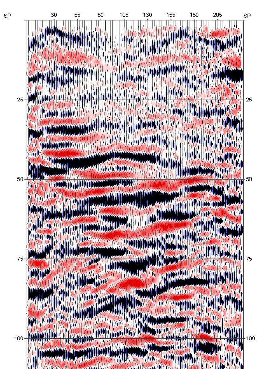
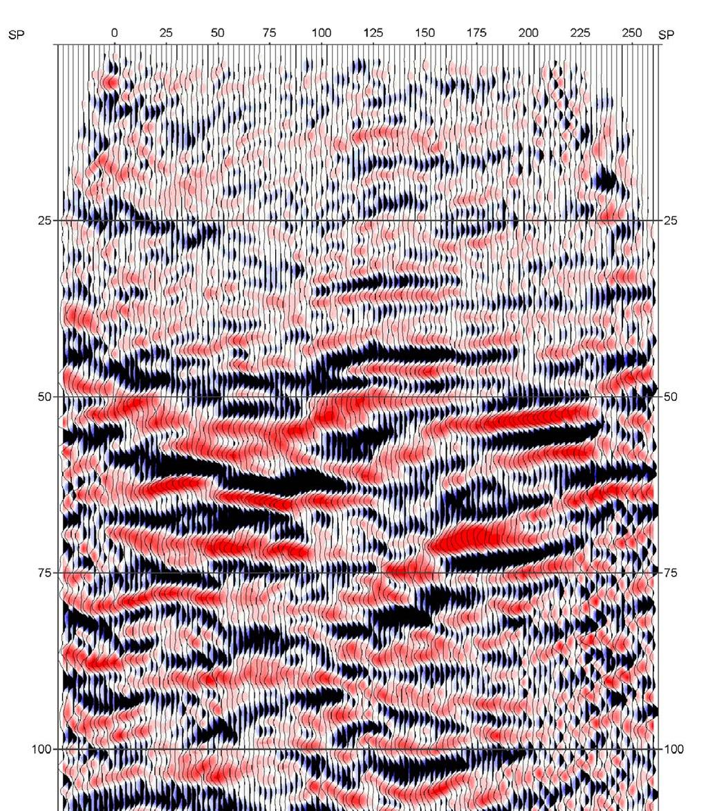
6 Page Survey Results 4.1 Discussion of GPR Survey Results Results of the additional GPR survey indicated the presence of two welldefined, relatively continuous sets of GPR reflectors at depth ranges of 5 to 8 ft bls and 12 to 25 ft bls. The upper GPR reflector set likely correlates to the interface between the unsaturated and saturated soils (water table). The lower GPR reflector set is likely associated with some change in lithological conditions at that depth range. One GPR anomaly area was identified at the site during this phase of the investigation. The anomaly area is designated as GPR Anomaly 3 on Figure 1. GPR Anomaly 3 is elliptical in shape with total area of approximately 60 square ft. The anomaly is located southwest of the water tower. The apparent vertical relief of the upper portion of the anomaly area is 1 to 3 ft as characterized by the observed minor downwarping of the GPR reflector set. A localized increase in the depth of penetration of the GPR signal was also observed within the anomaly area. The apparent center of the feature is characterized as the area of maximum penetration of the GPR signal. The previously identified GPR anomalies (GPR Anomaly 1 and 2) are also shown on Figure 1. The anomalies are numbered in order of significance with GPR Anomaly 1 being the most significant and GPR Anomaly 3 being the least significant. 4.2 Discussion of Seismic Reflection Survey Results The final processed high-resolution seismic reflection sections are presented in Appendix 1 on Figures 2, 3, 4 and 5. Seismic reflection sections illustrate geologic layers as continuous ( coherent ) horizons that can be traced across the full section. Disturbances such as faults, sinkholes, and cavities are observed as corresponding offsets or loss of continuity in these reflecting horizons. The horizontal scale on these sections is merely distance along the particular transect. The vertical scale is the reflection time. That is, it is the time taken from the moment of the hammer blow for the seismic wave to travel down to the geologic horizon, reflect/echo from it, and travel back up to the ground surface. To convert these times to actual depth, we need to know or approximate wave speed in the subsurface or have a deep borehole for calibration. Since such borehole velocity information was not available at the site, approximate velocity values for the type of soils encountered at the site were used. The velocities used to calculate the depths were 1,000 feet per second for unsaturated soils, 5,000 feet per second for saturated soils, and 6,000 feet per second for weathered limestone. If we estimate
7 Page 4 the depth to the bottom of the cap rock as being approximately 75 feet bls, then the reflection (two-way time) from the bottom of rock should be observed at a time of approximately 40 to 50 milliseconds. The seismic data was of acceptable high quality. On the seismic cross sections, there is a strong, mostly consistent reflection (highlighted in yellow) that occurs near the 45 millisecond mark. It is suspected that this reflection is from the top of rock. The four seismic lines tie together very well (i.e. they are imaging the same reflection character at the same times), which indicates that the data is consistent and of high quality across the site. Line 1 (Figure 2) shows the reflector slightly dipping down to the west. However, there are no obvious disruptions or discontinuites on the seismic reflections of Line 1. We do not see indications on Line 1 that would be consistent with potential karst development. Line 2 (Figure 3) shows a minor deflection of the reflector. The center of this area is located at a horizontal distance of 135 to 150 ft along Line 2. This area is shown as Seismic Anomaly 2 on Figure 1, 3 and 4. It is noted that there are no apparent disruptions to this reflector and therefore, it is likely that this minor anomaly is not indicative of karst activity. Line 3 (Figure 4) shows the same minor deflection of the reflector that was identified on Line 2. The center of this area is located at a horizontal distance of 70 to 90 ft along Line 3. This area is shown as Seismic Anomaly 2 on Figure 1, 3 and 4. It is again noted that there are no apparent disruptions to this reflector and therefore, it is likely that this minor anomaly is not indicative of karst activity. However, due to the fact that this feature was visible on two crossing lines, it was identified as a possible anomalous feature. Line 4 (Figure 5) shows an area of significant downwarping of the suspected top of rock reflector and discontinuities in the underlying and overlying reflectors. This area is identified as Seismic Anomaly 1 on Figures 1 and 5. The location of this feature corresponds well to the location of the surface depression and to the location of the previously identified GPR Anomaly 1. The anomalous conditions are located at a horizontal distance of 45 to 95 ft along Line 4. It noted that the reflectors from Line 4 appear to return to an undisturbed state at a horizontal distance of 100 ft, which is approximately 20 ft north of the fence and 75 ft north of the center of the water tower. Accordingly, based on the results of the combined GPR and seismic reflection studies the sinkhole feature does not appear to extend underneath the water tower.
8 APPENDIX 1 FIGURES AND EXAMPLE OF GPR ANOMALY 3
9
10

11

12
13

14 Water Table Soil Layer GPR Anomaly 3 GPR Transect 1 Showing Example of GPR Anomaly 3
15 A2-1 APPENDIX 2 DESCRIPTION OF GEOPHYSICAL METHODS, SURVEY METHODOLOGIES AND LIMITATIONS A2.1 On Site Measurements The measurements that were collected and used to create the site map were made using a fiberglass measuring tape. The degree of accuracy of such an approach is typically +/- 5% for lengths and +/- 2.5 degrees for angles. A2.2 Ground Penetrating Radar Ground Penetrating Radar (GPR) consists of a set of integrated electronic components that transmits high frequency (200 to 1500 megahertz [MHz]) electromagnetic waves into the ground and records the energy reflected back to the ground surface. The GPR system consists of an antenna, which serves as both a transmitter and receiver, and a profiling recorder that both processes the incoming signal and provides a graphic display of the data. The GPR data can be reviewed as both printed hard copy output or recorded on the profiling recorder s hard drive for later review. GeoView uses a Mala GPR system. Geological characterization studies are typically conducted using a 250 MHz antenna. A GPR survey provides a graphic cross-sectional view of subsurface conditions. This cross-sectional view is created from the reflections of repetitive short-duration electromagnetic (EM) waves that are generated as the antenna is pulled across the ground surface. The reflections occur at the subsurface contacts between materials with differing electrical properties. The electrical property contrast that causes the reflections is the dielectric permittivity that is directly related to conductivity of a material. The GPR method is commonly used to identify such targets as underground utilities, underground storage tanks or drums, buried debris, voids or geological features. The greater the electrical contrast between the surrounding earth materials and target of interest, the greater the amplitude of the reflected return signal. Unless the buried object is metal, only part of the signal energy will be reflected back to the antenna with the remaining portion of the signal continuing to propagate downward to be reflected by deeper features. If there is little or no electrical contrast between the target interest and surrounding earth materials it will be very difficult if not impossible to identify the object using GPR. The depth of penetration of the GPR signal is very site specific and is controlled by two primary factors: subsurface soil conditions and selected antenna frequency. The GPR signal is attenuated (absorbed) as is passes through earth
16 A2-2 materials. As the energy of the GPR signal is diminished due to attenuation, the energy of the reflected waves is reduced, eventually to the level that the reflections can no longer be detected. As the conductivity of the earth materials increases, the attenuation of the GPR signal increases thereby reducing the signal penetration depth. In Florida, the typical soil conditions that severely limit GPR signal penetration are near-surface clays and/or organic materials. The depth of penetration of the GPR signal is also reduced as the antenna frequency is increased. However, as antenna frequency is increased the resolution of the GPR data is improved. Therefore, when designing a GPR survey a tradeoff is made between the required depth of penetration and desired resolution of the data. As a rule, the highest frequency antenna that will still provide the desired maximum depth of penetration should be used. A GPR survey is conducted along survey lines (transects) that are measured paths along which the GPR antenna is moved. Electronic marks are placed in the data by the operator at designated points along the GPR transects. These marks allow for a correlation between the GPR data and the position of the GPR antenna on the ground. For geological characterization surveys, the GPR survey is conducted along a set of perpendicularly orientated transects. The survey is conducted in two directions because subsurface features such as sinkholes are often asymmetric. Spacing between the transects typically ranges from 10 to 50 feet. Closely spaced grids are used when the objective of the GPR survey is to identify all sinkhole features within a project site. Coarser grids are used when the objective is to provide a general overview of site conditions. After completion of a survey using a given grid spacing, additional more-closely spaced GPR transects are often performed to better characterize sinkhole features identified by the initial survey. This information can be used to provide recommended locations for geotechnical borings. Depth estimates to the top of lithological contacts or sinkhole features are determined by dividing the time of travel of the GPR signal from the ground surface to the top of the feature by the velocity of the GPR signal. The velocity of the GPR signal is usually obtained from published tables of velocities for the type and condition (saturated vs. unsaturated) of soils underlying the site. The accuracy of GPR-derived depths typically ranges from 20 to 40 percent of the total depth.
17 A2-3 A2.3 Seismic Reflection Seismic reflection profiling involves the measurement of the two-way travel time of seismic waves transmitted from surface and reflected back to the surface at the interfaces between contrasting geological layers. Reflection of the transmitted energy will only occur when there is a contrast in the acoustic impedance (product of the seismic velocity and density) between these layers. The strength of the contrast in the acoustic impedance of the two layers determines the amplitude of the reflected signal. The reflected signal is detected on surface using an array of high frequency geophones (typically 24-96). As with seismic refraction, the seismic energy is provided by a 'shot' on surface. For shallow applications this will normally comprise a hammer and plate, weight drop or explosive charge. In most reflection surveys shots are deployed at a number of different positions in relation to the geophone array in order to obtain reflections from the same point on the interface at different geophones in the array. Each common point of reflection is termed a common mid-point (CMP) and the number of times each one is sampled determines the 'fold coverage' for the survey. Traces relating to the same CMP are stacked together to increase the signal-to-noise ratio of the survey before being combined with other CMP's stacked traces to produce a reflection profile. In order to stack related CMP traces a stacking velocity is applied to each trace. This accounts for the difference in two-way travel time between the normal incidence reflection (vertical travel path below the shot) and those at increasing offsets from the shot (known as the normal moveout or NMO). The stacking velocity will vary down the trace to take account of the increase in velocity with depth for each reflection event. Interpretation and Limitations of Geophysical Data The analysis and collection of geophysical data is both a technical and interpretative skill. The technical aspects of the work are learned from both training and experience. Having the opportunity to compare data collected in numerous settings to the results from geotechnical studies performed at the same locations develops interpretative skills for geological characterization studies. The ability to collect interpretable information at a project site is limited by the attenuation (absorption) of the signal by underlying soils. Once the signal has been attenuated at a particular depth, information regarding deeper geological conditions will not be obtained. GPR and seismic data can only resolve subsurface features that have a sufficient electrical or density contrast between the feature in question and surrounding earth materials. If an insufficient contrast is present, the
18 A2-4 subsurface feature will not be identified. GeoView can make no warranties or representations of geological conditions that may be present beyond the depth of investigation or resolving capability of the equipment or in areas that were not accessible to the geophysical investigation.
19 FINAL REPORT GEOPHYSICAL INVESTIGATION TANK NO. 6 SITE PLANT CITY, FL Prepared for Madrid Engineering Group, Inc. Bartow, FL Prepared by GeoView, Inc. St. Petersburg, FL
20 January 17, 2010 Mr. Larry Madrid, P.E. Madrid Engineering Group, Inc. P.O. Box 2506 Bartow, FL Subject: Transmittal of Final Report for Geophysical Investigation Tank No. 6 Site - Plant City, FL GeoView Project Number 7837 Dear Mr. Madrid, GeoView, Inc. (GeoView) is pleased to submit the final report that summarizes and presents the results of the geophysical investigation conducted at the Tank No. 6 Site. Ground penetrating radar was used to evaluate near-surface geological conditions. GeoView appreciates the opportunity to have assisted you on this project. If you have any questions or comments about the report, please contact us. GEOVIEW, INC. Michael J. Wightman, P.G. President Florida Professional Geologist Number 1423 Chris Taylor, P.G. Vice President Florida Professional Geologist Number 2256 A Geophysical Services Company 4610 Central Avenue Tel.: (727) St. Petersburg, FL Fax: (727)
21 Page Introduction The site was located along National Guard Drive in Plant City, Florida. Prior to the geophysical investigation, two surface depressions had formed north of Water Tank No. 6. The first depression was approximately 40 feet (ft) in diameter, 2 ft deep and located approximately 70 ft north of the water tank. The second depression was approximately 10 ft in diameter, 3 ft deep and located approximately 160 ft north of the water tank. The purpose of the geophysical investigation was to help characterize nearsurface geological conditions in the area of the depressions and to identify subsurface features that may be associated with sinkhole activity. The survey area included the areas surrounding the depressions and the water tank. The location of the geophysical survey area is provided on Figure 1. The investigation was conducted on January 13, A discussion of the field methods used to generate the report figures is provided in Appendix A Description of Geophysical Investigation 2.1 Ground Penetrating Radar Survey A GPR survey was conducted around the depressions and the water tank. The GPR survey was conducted along a series of perpendicular transects spaced approximately 10 ft apart. The GPR data was collected with a Mala radar system. The GPR settings used for the survey are presented in Table 1. Table 1 GPR Equipment Settings Used for Exterior and Interior GPR Surveys Location Antenna Frequency Time Range (nano-seconds) Estimated Depth of GPR Signal Penetration Exterior 250 MHz 1/ to 35 ft bls 1/ MHz means mega-hertz and is the mid-range operating frequency of the GPR antenna. A description of the GPR technique and the methods employed for geological characterization studies is provided in Appendix A Identification of Possible Sinkhole Features Using GPR The features observed on GPR data that are most commonly associated with sinkhole activity are: A downwarping of GPR reflector sets, that are associated with suspected lithological contacts, toward a common center. Such features
22 Page 2 typically have with a bowl or funnel shaped configuration and can be associated with a deflection of overlying sediment horizons caused by the migration of sediments into voids in the underlying limestone. If the GPR reflector sets are sharply downwarping and intersect, they can create bow-tie shaped GPR reflection feature, which often designates the apparent center of the GPR anomaly. A localized significant increase in the depth of the penetration and/or amplitude of the GPR signal response. The increase in GPR signal penetration depth or amplitude is often associated with either a localized increase in sand content at depth or decrease in soil density. An apparent discontinuity in GPR reflector sets, that are associated with suspected lithological contacts. The apparent discontinuities and/or disruption of the GPR reflector sets may be associated with the downward migration sediments. The greater the severity of these features or a combination of these features the greater the likelihood that the identified feature is a sinkhole. It is not possible based on the GPR data alone to determine if an identified feature is a sinkhole or, more importantly, whether that feature is an active sinkhole. 4.0 Survey Results 4.1 Discussion of GPR Survey Results Results of the GPR survey indicated the presence of two well-defined, relatively continuous sets of GPR reflectors at depth ranges of 5 to 7 ft bls and 12 to 25 ft bls. The upper GPR reflector set likely correlates to the interface between the unsaturated and saturated soils (water table). The lower GPR reflector set is likely associated with some change in lithological conditions at that depth range. Description of GPR Anomalies Two GPR anomaly areas were identified at the site. The anomaly areas are designated as GPR Anomalies 1 and 2 on Figure 1. The anomalies are numbered in order of significance with GPR Anomaly 1 being the most significant and GPR Anomaly 2 being the least significant. A description of each of the anomalies is as follows: GPR Anomaly 1 GPR Anomaly 1 is semi-elliptical in shape with total area of approximately 1,300 square ft. The anomaly is located north of the water tank and the boundaries of the anomaly are almost identical to the outer boundary of the larger surface
23 Page 3 depression. The apparent vertical relief of the upper portion of the anomaly area is 10 to 20 ft as characterized by the observed downwarping of the GPR reflector set. A localized increase in the depth of penetration of the GPR signal was also observed within the anomaly area. The apparent center of the feature is characterized as the area of maximum downwarping and/or discontinuity of the previously referenced GPR reflectors. GPR Anomaly 2 GPR Anomaly 2 is elliptical in shape with total area of approximately 130 square ft. The anomaly is located northwest of the water tank and west of the larger surface depression. The apparent vertical relief of the upper portion of the anomaly area is 3 to 5 ft as characterized by the observed downwarping of the GPR reflector set. A localized increase in the depth of penetration of the GPR signal was also observed within the anomaly area. The apparent center of the feature is characterized as the area of maximum downwarping of the previously referenced GPR reflectors. In addition to the two GPR anomalies, there was one large area that was characterized by a minor downwarping of the GPR reflectors. This feature covered much of the central portion of the survey area and was centered about GPR Anomaly 1. With the exception of the area within Anomaly 1, there were no breaks or other apparent discontinuities of the GPR reflector within this feature. It is suspected that this feature may be indicative of a relic paleo-sink which is currently stabilized. It is suspected that the only the unstable portions of this feature are within GPR anomalies 1 and 2. The GPR did not identify any anomalous areas near the northern, smaller depression. However, for safety reasons, GPR data was not collected directly across this depression. It is suspected that the karst feature associated with this depression area has near-vertical walls and does not extend much beyond the boundaries of the depression (within the depth range of the GPR signal).
24 APPENDIX 1 FIGURE, PHOTOGRAPHS, AND EXAMPLES OF GPR ANOMALIES
25


26 Photograph 1 Facing south toward the larger depression Photograph 2 Facing south toward the smaller depression with the larger depression and water tank in the background Photograph 3 Facing north toward the larger depression


27 Water Table Soil Layer GPR Anomaly 1 GPR Transect 8 Showing Example of GPR Anomaly 1 GPR Anomaly 2 GPR Anomaly 1 GPR Transect 24 Showing Example of GPR Anomaly 2
28 A2-1 APPENDIX 2 DESCRIPTION OF GEOPHYSICAL METHODS, SURVEY METHODOLOGIES AND LIMITATIONS A2.1 On Site Measurements The measurements that were collected and used to create the site map were made using a fiberglass measuring tape. Right angles were estimated using the exterior walls of the residence. The degree of accuracy of such an approach is typically +/- 5% for lengths and +/- 2.5 degrees for angles. A2.2 Ground Penetrating Radar Ground Penetrating Radar (GPR) consists of a set of integrated electronic components that transmits high frequency (200 to 1500 megahertz [MHz]) electromagnetic waves into the ground and records the energy reflected back to the ground surface. The GPR system consists of an antenna, which serves as both a transmitter and receiver, and a profiling recorder that both processes the incoming signal and provides a graphic display of the data. The GPR data can be reviewed as both printed hard copy output or recorded on the profiling recorder s hard drive for later review. GeoView uses a Mala GPR system. Geological characterization studies are typically conducted using a 250 MHz antenna. A GPR survey provides a graphic cross-sectional view of subsurface conditions. This cross-sectional view is created from the reflections of repetitive short-duration electromagnetic (EM) waves that are generated as the antenna is pulled across the ground surface. The reflections occur at the subsurface contacts between materials with differing electrical properties. The electrical property contrast that causes the reflections is the dielectric permittivity that is directly related to conductivity of a material. The GPR method is commonly used to identify such targets as underground utilities, underground storage tanks or drums, buried debris, voids or geological features. The greater the electrical contrast between the surrounding earth materials and target of interest, the greater the amplitude of the reflected return signal. Unless the buried object is metal, only part of the signal energy will be reflected back to the antenna with the remaining portion of the signal continuing to propagate downward to be reflected by deeper features. If there is little or no electrical contrast between the target interest and surrounding earth materials it will be very difficult if not impossible to identify the object using GPR. The depth of penetration of the GPR signal is very site specific and is controlled by two primary factors: subsurface soil conditions and selected antenna
29 A2-2 frequency. The GPR signal is attenuated (absorbed) as is passes through earth materials. As the energy of the GPR signal is diminished due to attenuation, the energy of the reflected waves is reduced, eventually to the level that the reflections can no longer be detected. As the conductivity of the earth materials increases, the attenuation of the GPR signal increases thereby reducing the signal penetration depth. In Florida, the typical soil conditions that severely limit GPR signal penetration are near-surface clays and/or organic materials. The depth of penetration of the GPR signal is also reduced as the antenna frequency is increased. However, as antenna frequency is increased the resolution of the GPR data is improved. Therefore, when designing a GPR survey a tradeoff is made between the required depth of penetration and desired resolution of the data. As a rule, the highest frequency antenna that will still provide the desired maximum depth of penetration should be used. A GPR survey is conducted along survey lines (transects) that are measured paths along which the GPR antenna is moved. Electronic marks are placed in the data by the operator at designated points along the GPR transects. These marks allow for a correlation between the GPR data and the position of the GPR antenna on the ground. For geological characterization surveys, the GPR survey is conducted along a set of perpendicularly orientated transects. The survey is conducted in two directions because subsurface features such as sinkholes are often asymmetric. Spacing between the transects typically ranges from 10 to 50 feet. Closely spaced grids are used when the objective of the GPR survey is to identify all sinkhole features within a project site. Coarser grids are used when the objective is to provide a general overview of site conditions. After completion of a survey using a given grid spacing, additional more-closely spaced GPR transects are often performed to better characterize sinkhole features identified by the initial survey. This information can be used to provide recommended locations for geotechnical borings. Depth estimates to the top of lithological contacts or sinkhole features are determined by dividing the time of travel of the GPR signal from the ground surface to the top of the feature by the velocity of the GPR signal. The velocity of the GPR signal is usually obtained from published tables of velocities for the type and condition (saturated vs. unsaturated) of soils underlying the site. The accuracy of GPR-derived depths typically ranges from 20 to 40 percent of the total depth. Interpretation and Limitations of GPR data
30 A2-3 The analysis and collection of GPR data is both a technical and interpretative skill. The technical aspects of the work are learned from both training and experience. Having the opportunity to compare GPR data collected in numerous settings to the results from geotechnical studies performed at the same locations develops interpretative skills for geological characterization studies. The ability of GPR to collect interpretable information at a project site is limited by the attenuation (absorption) of the GPR signal by underlying soils. Once the GPR signal has been attenuated at a particular depth, information regarding deeper geological conditions will not be obtained. GPR data can only resolve subsurface features that have a sufficient electrical contrast between the feature in question and surrounding earth materials. If an insufficient contrast is present, the subsurface feature will not be identified. GeoView can make no warranties or representations of geological conditions that may be present beyond the depth of investigation or resolving capability of the GPR equipment or in areas that were not accessible to the geophysical investigation.
Sabal Trail Pipeline Project Evaluation of Karst Topography and Sinkhole Potential for Pipeline and Facilities
 November 11, 2014 Sabal Trail Pipeline Project Evaluation of Karst Topography and Sinkhole Potential for Pipeline and Facilities Gulf Interstate Engineering Attention: Mr. Denys Stavnychyi - Project Engineer
M E M O R A N D U M. Mr. Jonathan K. Thrasher, P.E. and Mr. Ian Kinnear, P.E. PSI
 M E M O R A N D U M TO: FROM: Mr. Mark Schilling Gulf Interstate Engineering Mr. Jonathan K. Thrasher, P.E. and Mr. Ian Kinnear, P.E. PSI DATE: November 11, 2014 RE: Summary of Findings Geotechnical Study
FINAL REPORT GEOPHYSICAL INVESTIGATION VILLAGE ALHAMBRA RETENTION POND SITE THE VILLAGES, FLORIDA
 FINAL REPORT GEOPHYSICAL INVESTIGATION VILLAGE ALHAMBRA RETENTION POND SITE THE VILLAGES, FLORIDA Prepared for Andreyev Engineering, Inc. Oxford, FL Prepared by GeoView, Inc. St. Petersburg, FL August
Walkaway Seismic Experiments: Stewart Gulch, Boise, Idaho
 Walkaway Seismic Experiments: Stewart Gulch, Boise, Idaho Lee M. Liberty Center for Geophysical Investigation of the Shallow Subsurface Boise State University Boise, Idaho 1. Summary CGISS conducted walkaway
GEOPHYSICAL SITE CHARACTERIZATION IN SUPPORT OF HIGHWAY EXPANSION PROJECT
 GEOPHYSICAL SITE CHARACTERIZATION IN SUPPORT OF HIGHWAY EXPANSION PROJECT * Shane Hickman, * Todd Lippincott, * Steve Cardimona, * Neil Anderson, and + Tim Newton * The University of Missouri-Rolla Department
Lima Project: Seismic Refraction and Resistivity Survey. Alten du Plessis Global Geophysical
 Lima Project: Seismic Refraction and Resistivity Survey Alten du Plessis Global Geophysical Report no 0706/2006 18 December 2006 Lima Project: Seismic Refraction and Resistivity Survey by Alten du Plessis
Geophysics for Environmental and Geotechnical Applications
 Geophysics for Environmental and Geotechnical Applications Dr. Katherine Grote University of Wisconsin Eau Claire Why Use Geophysics? Improve the quality of site characterization (higher resolution and
APPENDIX C GEOPHYSICAL REPORT
 APPENDIX C GEOPHYSICAL REPORT GEOPHYSICAL ENGINEERING SURVEY REPORT 700 E 241 st Street NOVA PROJECT NUMBER 15-0522 DATED January 27, 2015 PREPARED FOR: LANGAN Long Warf Maritime Center New Haven, CT 06511
IMAGING OF DEEP SINKHOLES USING THE MULTI-ELECTRODE RESISTIVITY IMPLANT TECHNIQUE (MERIT) CASE STUDIES IN FLORIDA
 CASE STUDIES IN FLORIDA") IMAGING OF DEEP SINKHOLES USING THE MULTI-ELECTRODE RESISTIVITY IMPLANT TECHNIQUE (MERIT) CASE STUDIES IN FLORIDA David Harro The G3 Group, 2509 Success Drive, Suite 1, Odessa, FL 33556, david.harro@geo3group.com
IMAGING OF DEEP SINKHOLES USING THE MULTI-ELECTRODE RESISTIVITY IMPLANT TECHNIQUE (MERIT) CASE STUDIES IN FLORIDA David Harro The G3 Group, 2509 Success Drive, Suite 1, Odessa, FL 33556, david.harro@geo3group.com
Ground-Water Exploration in the Worthington Area of Nobles County: Summary of Seismic Data and Recent Test Drilling Results
 Ground-Water Exploration in the Worthington Area of Nobles County: Summary of Seismic Data and Recent Test Drilling Results Jim Berg and Todd Petersen Geophysicists, DNR Waters January 2000 Table of Contents
KARST MAPPING WITH GEOPHYSICS AT MYSTERY CAVE STATE PARK, MINNESOTA
 KARST MAPPING WITH GEOPHYSICS AT MYSTERY CAVE STATE PARK, MINNESOTA By Todd A. Petersen and James A. Berg Geophysics Program Ground Water and Climatology Section DNR Waters June 2001 1.0 Summary A new
A GPR ASSESSMENT OF THE PREHISTORIC NAPLES CANAL NAPLES, FLORIDA ARCHAEOLOGICAL AND HISTORICAL CONSERVANCY, INC.
 A GPR ASSESSMENT OF THE PREHISTORIC NAPLES CANAL NAPLES, FLORIDA ARCHAEOLOGICAL AND HISTORICAL CONSERVANCY, INC. AHC TECNICAL REPORT NO. 1004 DECEMBER 2013 A GPR ASSESSMENT OF THE PREHISTORIC NAPLES CANAL
High Resolution Geophysics: A Better View of the Subsurface. By John Jansen, P.G., Ph.D., Aquifer Science and Technology
 High Resolution Geophysics: A Better View of the Subsurface By John Jansen, P.G., Ph.D., Aquifer Science and Technology Geologist Use Only Part of the Information Available To Them Most Geologist rely
LECTURE 10. Module 3 : Field Tests in Rock 3.6 GEOPHYSICAL INVESTIGATION
 LECTURE 10 3.6 GEOPHYSICAL INVESTIGATION In geophysical methods of site investigation, the application of the principles of physics are used to the study of the ground. The soil/rock have different characteristics
Oil and Gas Research Institute Seismic Analysis Center Faults Detection Using High-Resolution Seismic Reflection Techniques
 Oil and Gas Research Institute Seismic Analysis Center Faults Detection Using High-Resolution Seismic Reflection Techniques Ghunaim T. Al-Anezi (KACST) March 2013 1 Objectives The objective of the survey
EXTREMELY FAST IP USED TO DELINEATE BURIED LANDFILLS. Norman R. Carlson, Cris Mauldin Mayerle, and Kenneth L. Zonge
 EXTREMELY FAST IP USED TO DELINEATE BURIED LANDFILLS Norman R. Carlson, Cris Mauldin Mayerle, and Kenneth L. Zonge Zonge Engineering and Research Organization, Inc. 3322 East Fort Lowell Road Tucson, Arizona,
STATISTICAL ANALYSIS OF GPR AND SPT METHODS FOR SINKHOLE INVESTIGATION IN COVERED KARST TERRAIN, WEST-CENTRAL FLORIDA, USA
 STATISTICAL ANALYSIS OF GPR AND SPT METHODS FOR SINKHOLE INVESTIGATION IN COVERED KARST TERRAIN, WEST-CENTRAL FLORIDA, USA Henok Kiflu, Sarah Kruse Dept. of Geology, University of South Florida, 4202 E.
Application of Ground Penetrating Radar for hydro-geological study
 Journal of Scientific & Industrial Research Vol. 65, February 2006, pp. 160-164 Application of Ground Penetrating Radar for hydro-geological study K K K Singh* Central Mining Research Institute, Dhanbad
GPR AS A COST EFFECTIVE BEDROCK MAPPING TOOL FOR LARGE AREAS. Abstract
 GPR AS A COST EFFECTIVE BEDROCK MAPPING TOOL FOR LARGE AREAS Dr. Jutta L. Hager, Hager GeoScience, Inc., Waltham, MA Mario Carnevale, Hager GeoScience, Inc., Waltham, MA Abstract Hager GeoScience, Inc.
Seismic tests at Southern Ute Nation coal fire site
 Seismic tests at Southern Ute Nation coal fire site Sjoerd de Ridder and Seth S. Haines ABSTRACT We conducted a near surface seismic test at the Southern Ute Nation coal fire site near Durango, CO. The
Geophysical Site Investigation (Seismic methods) Amit Prashant Indian Institute of Technology Gandhinagar
 Amit Prashant Indian Institute of Technology Gandhinagar") Geophysical Site Investigation (Seismic methods) Amit Prashant Indian Institute of Technology Gandhinagar Short Course on Geotechnical Aspects of Earthquake Engineering 04 08 March, 2013 Seismic Waves
Geophysical Site Investigation (Seismic methods) Amit Prashant Indian Institute of Technology Gandhinagar Short Course on Geotechnical Aspects of Earthquake Engineering 04 08 March, 2013 Seismic Waves
PART A: Short-answer questions (50%; each worth 2%)
") PART A: Short-answer questions (50%; each worth 2%) Your answers should be brief (just a few words) and may be written on these pages if you wish. Remember to hand these pages in with your other exam pages!
PART A: Short-answer questions (50%; each worth 2%) Your answers should be brief (just a few words) and may be written on these pages if you wish. Remember to hand these pages in with your other exam pages!
P Wave Reflection and Refraction and SH Wave Refraction Data Processing in the Mooring, TN Area
 P Wave Reflection and Refraction and SH Wave Refraction Data Processing in the Mooring, TN Area Abstract: Author: Duayne Rieger Home Institution: Slippery Rock University of Pennsylvania REU Institution:
Seismic Reflection Imaging across the Johnson Ranch, Valley County, Idaho
 Seismic Reflection Imaging across the Johnson Ranch, Valley County, Idaho Report Prepared for the Skyline Corporation Lee M. Liberty Center for Geophysical Investigation of the Shallow Subsurface (CGISS)
SEISMIC SURVEYS FOR IMAGING THE REGOLITH
 SEISMIC SURVEYS FOR IMAGING THE REGOLITH Barry Drummond Geoscience Australia. PO Box 378, Canberra, ACT 2601. E-mail: barry.drummond@ga.gov.au 1. INTRODUCTION Seismic reflection and refraction imaging
GPR surveys at Nõmmküla Detection of underground water routes
 GPR surveys at Nõmmküla 2009 Detection of underground water routes Tomi Herronen & Timo Saarenketo 2009 1. Introduction The purpose of this survey was to locate possible underground water routes (rivers)
Engineering Geophysical Application to Mine Subsidence Risk Assessment
 Engineering Geophysical Application to Mine Subsidence Risk Assessment By: Kanaan Hanna, Sr. Mining Engineer Steve Hodges, Sr. Geophysicist Jim Pfeiffer, Sr. Geophysicist Dr. Keith Heasley, Professor West
INTRODUCTION TO APPLIED GEOPHYSICS
 INTRODUCTION TO APPLIED GEOPHYSICS EXPLORING THE SHALL0W SUBSURFACE H. Robert Burger Anne F. Sheehan Craig H.Jones VERSITY OF COLORADO VERSITY OF COLORADO W. W. NORTON & COMPANY NEW YORK LONDON Contents
In-seam GPR and 2-C seismic investigations at the Goderich, Ontario salt mine
 In-seam GPR and 2-C seismic investigations at the Goderich, Ontario salt mine Jill Belisle and Robert R. Stewart In-seam techniques ABSTRACT In-seam GPR and 2-C seismic techniques used in conjunction with
SEISMIC RADAR AND ELECTRICAL TECHNIQUES FOR WASTE DISPOSAL ASSESSMENT. M. Pipan, G. Dal Moro, E. Forte & M. Sugan
 SEISMIC RADAR AND ELECTRICAL TECHNIQUES FOR WASTE DISPOSAL ASSESSMENT M. Pipan, G. Dal Moro, E. Forte & M. Sugan Department of Geological, Environmental and Marine Sciences, University of Trieste Via Weiss,
Applied Geophysics for Environmental Site Characterization and Remediation
 Applied Geophysics for Environmental Site Characterization and Remediation MSECA Webinar September 24, 2015 John Mundell, P.E., L.P.G. Ryan Brumbaugh, L.P.G. MUNDELL & ASSOCIATES, INC. Webinar Objective
3-D ground-penetrating radar surveys on a frozen river lagoon
 3-D ground-penetrating radar surveys on a frozen river lagoon Monica Moldoveanu and Robert R. tewart ABTRACT Ground-penetrating radar (GPR) surveys were acquired at Bowness Park, Calgary to characterize
Geophysical Applications GPR Ground Penetrating Radar
 Overview: Basics of GPR Radar-wave velocity, attenuation and skin depth Modes of acquisition The Radar-range equation Dielectric properties of materials and relation to porosity Case studies [Archeology,
Ultra high-resolution seismic and GPR imaging of permafrost. Devon Island, Nunavut
 Ultra high-resolution seismic and GPR imaging of permafrost. Devon Island, Nunavut Carlos E. Nieto* and Robert R. Stewart CREWES. The University of Calgary, 2500 University Dr., N.W., Calgary, AB, T2N
A GPR ASSESSMENT OF THE NAPLES CANAL 8CR59: PHASE II NAPLES, FLORIDA ARCHAEOLOGICAL AND HISTORICAL CONSERVANCY, INC.
 A GPR ASSESSMENT OF THE NAPLES CANAL 8CR59: PHASE II NAPLES, FLORIDA ARCHAEOLOGICAL AND HISTORICAL CONSERVANCY, INC. AHC TECNICAL REPORT NO. 1023 JUNE 2014 A GPR ASSESSMENT OF THE NAPLES CANAL 8CR59: PHASE
SEISMIC REFRACTION ANALYSIS OF EAST RIVER FLATS MINNEAPOLIS MINNESOTA A THESIS SUBMITTED TO THE FACULTY OF UNIVERSITY OF MINNESOTA AUTUMN HAAGSMA
 SEISMIC REFRACTION ANALYSIS OF EAST RIVER FLATS MINNEAPOLIS MINNESOTA A THESIS SUBMITTED TO THE FACULTY OF UNIVERSITY OF MINNESOTA BY AUTUMN HAAGSMA IN PARTIAL FULFILLMENT OF THE REQUIREMENTS FOR THE DEGREE
Taseko Prosperity Gold-Copper Project. Appendix 3-6-Q
 Taseko Prosperity Gold-Copper Project Appendix 3-6-Q KNIGHT & PIESOLD LTD. AND TASEKO MINES LIMITED REPORT ON SEISMIC REFRACTION AND REFLECTION INVESTIGATION PROSPERITY PROJECT, FISH LAKE AREA WILLIAMS
ERTH2020 Introduction to Geophysics The Seismic Method. 1. Basic Concepts in Seismology. 1.1 Seismic Wave Types
 ERTH2020 Introduction to Geophysics The Seismic Method 1. Basic Concepts in Seismology 1.1 Seismic Wave Types Existence of different wave types The existence of different seismic wave types can be understood
Near-Surface Seismic Reflection Applications
 Near-Surface Seismic Reflection Applications Don Steeples, The University of Kansas, Lawrence, KS USA Abstract Nonintrusive methods of gaining knowledge about the Earth s subsurface comprise several of
Chapter 7: Reflection Seismology Homework Solutions (Jan. 2010)
") Chapter 7: eflection Seismology Homework Solutions (Jan. 200). Why do marine seismic reflection surveys not record (a) S waves? (b) refracted rays? 2 μ a) For ideal fluid, μ=0, thus, v s = = 0 ρ b) eflection
Chapter 7: eflection Seismology Homework Solutions (Jan. 200). Why do marine seismic reflection surveys not record (a) S waves? (b) refracted rays? 2 μ a) For ideal fluid, μ=0, thus, v s = = 0 ρ b) eflection
ambiguity in earth sciences IESO Geophysics Section Eddy hartantyo, Lab Geofisika FMIPA UGM
 ambiguity in earth sciences IESO Geophysics Section Eddy hartantyo, Lab Geofisika FMIPA UGM Pelatihan Tahap II IESO Teknik Geologi UGM Februari 2009 1 Introduction Photos from http://www.eegs.org/whatis/
Applications of finite-difference modelling to coalscale seismic exploration
 Applications of finite-difference modelling to coalscale seismic exploration Shaun Strong 1,2, Troy Peters 1 1. Velseis Pty Ltd 2 University of Queensland Introduction Geological environments with significant
11301 Reservoir Analogues Characterization by Means of GPR
 11301 Reservoir Analogues Characterization by Means of GPR E. Forte* (University of Trieste) & M. Pipan (University of Trieste) SUMMARY The study of hydrocarbon reservoir analogues is increasing important
Ground-penetrating radar (GPR) and shallow seismic surveys at Calgary International Airport, Alberta
 and shallow seismic surveys at Calgary International Airport, Alberta") Ground-penetrating radar (GPR) and shallow seismic surveys at Calgary International Airport, Alberta Robert R. Stewart, Han-xing Lu, and Don C. Lawton ABSTRACT A ground-penetrating radar survey was conducted
Ground-penetrating radar (GPR) and shallow seismic surveys at Calgary International Airport, Alberta Robert R. Stewart, Han-xing Lu, and Don C. Lawton ABSTRACT A ground-penetrating radar survey was conducted
THE UTILITY OF HORIZONTAL COMPONENT MEASUREMENTS IN RANDOM-WALK TEM SURVEYS. Abstract
 THE UTILITY OF HORIZONTAL COMPONENT MEASUREMENTS IN RANDOM-WALK TEM SURVEYS Norman R. Carlson, Zonge Engineering & Research Organization, Inc., Tucson, AZ Kenneth L. Zonge, Zonge Engineering & Research
Ardaman & Associates, Inc. Geotechnical, Environmental and Materials Consultants
 SUBSURFACE SOIL EXPLORATION 42-INCH FORCE MAIN REPLACEMENT CHIQUITA BOULEVARD S AND SW 34 TH STREET CAPE CORAL, LEE COUNTY, FLORIDA Ardaman & Associates, Inc. Geotechnical, Environmental and Materials
X040 Buried Sources and Receivers in a Karsted Desert Environment
 X040 Buried Sources and Receivers in a Karsted Desert Environment C. Berron* (CGGVeritas Services S.A.), E. Forgues (CGGVeritas Services S. A.), M. Jervis (Saudi Aramco), A. Bakulin (Saudi Aramco) & R.
A Case Study on Ground Subsidence Using Ground Penetrating Radar
 2012 International Conference on Environmental, Biomedical and Biotechnology IPCBEE vol.41 (2012) (2012) IACSIT Press, Singapore A Case Study on Ground Using Ground Penetrating Radar Nur Azwin Ismail +
Geophysical Investigation of a 19th Century Archeological Site, Boston College K. Corcoran, J. Hager, M. Carnevale
 Geophysical Investigation of a 19th Century Archeological Site, Boston College K. Corcoran, J. Hager, M. Carnevale Hager GeoScience, Inc., Waltham, MA ------------------------------------------------------------------------
Appendix B: Geophysical Data (Thesis Appendix, 2013)
") Utah State University From the SelectedWorks of David J Richey 2013 Appendix B: Geophysical Data (Thesis Appendix, 2013) David J Richey, Utah State University Available at: https://works.bepress.com/david_richey/2/
Utah State University From the SelectedWorks of David J Richey 2013 Appendix B: Geophysical Data (Thesis Appendix, 2013) David J Richey, Utah State University Available at: https://works.bepress.com/david_richey/2/
Static Corrections for Seismic Reflection Surveys
 Static Corrections for Seismic Reflection Surveys MIKE COX Volume Editors: Series Editor: Eugene F. Scherrer Roland Chen Eugene F. Scherrer Society of Exploration Geophysicists Tulsa, Oklahoma Contents
GEOSYNTEC CONSULTANTS
 GEOSYNTEC CONSULTANTS 2100 Main Street, Suite 150 Huntington Beach, CA 92648 USA Tel (714) 969-0800 Fax (714) 969-0820 15 February 2006 Ms. Tamara Zeier, P.E. Project Manager Project Navigator, Ltd. One
Source Wave Design for Downhole Seismic Testing
 Source Wave Design for Downhole Seismic Testing Downhole seismic testing (DST) has become a very popular site characterizing tool among geotechnical engineers. DST methods, such as the Seismic Cone Penetration
ZONGE GEOSCIENCES, INC.
 ZONGE GEOSCIENCES, INC. GEOPHYSICAL INVESTIGATION REPORT 2D Seismic Reflection Survey Crump Geyser Geothermal Prospect Warner Valley, Oregon Prepared for: John Casteel District Geologist Nevada Geothermal
Ground subsidence is a worldwide problem especially
 Ground Engineering: GPR A Case Study on Ground Subsidence Using Ground Penetrating Radar Nur Azwin Ismail and Rosli Saad Geophysics Section, School of Physics, Universiti Sains Malaysia Ground subsidence
Lesson 1 Introduction to geophysical methods Emanuele Forte
 Lesson 1 Introduction to geophysical methods Emanuele Forte 3 rd September 2016 Naxos, Greece 1 Outline - What is Geophysics - Base concepts: (Geo)Physical parameters Sensitivity Resolution - Active and
INTEGRATED GEOPHYSICAL CHARACTERIZATION AT A CONTAMINATED SITE. Abstract
 INTEGRATED GEOPHYSICAL CHARACTERIZATION AT A CONTAMINATED SITE Mario Carnevale, Hager GeoScience, Inc., Woburn, MA Jutta Hager, Hager GeoScience, Inc., Woburn, MA Brian R. Jones, Hager GeoScience, Inc.,
Tim Carr - West Virginia University
 Tim Carr - West Virginia University Understanding Seismic Data Resolution (Vertical and Horizontal) Common Depth Points (CDPs) Two way time (TWT) Time versus depth Interpretation of Reflectors 2 Able to
SEISMIC REFRACTION SURVEY RIPPABILITY STUDY
 SEISMIC REFRACTION SURVEY RIPPABILITY STUDY US 95A SILVER SPRINGS to FERNLEY LYON COUNTY August 2008 E.A. 73455 MATERIALS DIVISION SEISMIC REFRACTION SURVEY RIPPABILITY STUDY LYON COUNTY US 95A SILVER
 SHEET TITLE: DRAWN BY: J.M.CLARK FILE NO. CHECKED BY: W.S. JORDAN APPROVED BY: DATE: FIGURE SHEET TITLE: DRAWN BY: J.M.CLARK FILE NO. CHECKED BY: W.S. JORDAN APPROVED BY: DATE: FIGURE SPOTLIGHT Technical
Date: April 2, 2014 Project No.: Prepared For: Mr. Adam Kates CLASSIC COMMUNITIES 1068 E. Meadow Circle Palo Alto, California 94303
 City of Newark - 36120 Ruschin Drive Project Draft Initial Study/Mitigated Negative Declaration Appendix C: Geologic Information FirstCarbon Solutions H:\Client (PN-JN)\4554\45540001\ISMND\45540001 36120
Information From Walk-Away VSP and Cross-Hole DataUsing Various Wave Modes: Tower Colliery, South Sydney Basin
 Seismic Methods in Mineral Exploration Paper 58 Explor97 Master Page Explor97 Contents Previous Paper G O T O Author Index Section Contents Next Paper Information From Walk-Away VSP and Cross-Hole DataUsing
Although most karstic regions
 Urban Geophysics: Geophysical Signature of Mount Bonnell Fault and Its Karstic Features in Austin, TX by Mustafa Saribudak, Environmental Geophysics Associates, Austin, TX Although most karstic regions
M E M O R A N D U M. Mr. Jonathan K. Thrasher, P.E., Mr. Ian Kinnear, P.E. (FL) PSI
 PSI") M E M O R A N D U M TO: FROM: Mr. Mark Schilling Gulf Interstate Engineering Mr. Jonathan K. Thrasher, P.E., Mr. Ian Kinnear, P.E. (FL) PSI DATE: November 11, 2014 RE: Summary of Findings Geotechnical
M E M O R A N D U M TO: FROM: Mr. Mark Schilling Gulf Interstate Engineering Mr. Jonathan K. Thrasher, P.E., Mr. Ian Kinnear, P.E. (FL) PSI DATE: November 11, 2014 RE: Summary of Findings Geotechnical
DOWN-HOLE SEISMIC SURVEY AND VERTICAL ELECTRIC SOUNDINGS RABASKA PROJECT, LÉVIS, QUÉBEC. Presented to :
 DOWN-HOLE SEISMIC SURVEY AND VERTICAL ELECTRIC SOUNDINGS RABASKA PROJECT, LÉVIS, QUÉBEC Presented to : TERRATECH 455, René-Lévesque Blvd. West Montreal, Québec HZ 1Z3 Presented by : GEOPHYSICS GPR INTERNATIONAL
USE OF GEOPHYSICAL SURVEYS FOR FILL CHARACTERIZATION AND QUANTITY ESTIMATION AT BROWNFIELD SITES A CASE HISTORY. Abstract
 USE OF GEOPHYSICAL SURVEYS FOR FILL CHARACTERIZATION AND QUANTITY ESTIMATION AT BROWNFIELD SITES A CASE HISTORY John A. Mundell, Mundell & Associates, Inc., Indianapolis, IN Gregory B. Byer, Mundell &
Geophysical Exploration in Water Resources Assessment. John Mundell, P.E., L.P.G., P.G. Ryan Brumbaugh, L.P.G. Mundell & Associates, Inc.
 Geophysical Exploration in Water Resources Assessment John Mundell, P.E., L.P.G., P.G. Ryan Brumbaugh, L.P.G. Mundell & Associates, Inc. Presentation Objective Introduce the use of geophysical survey methods
MOUNT POLLEY MINING CORPORATION TECHNICAL REPORT ON MULTI-ELECTRODE RESISTIVITY AND SEISMIC REFRACTION SURVEYS MOUNT POLLEY TAILINGS DAM PROJECT
 MOUNT PLEY MINING CORPORATION TECHNICAL REPORT ON MULTI-ELECTRODE RESISTIVITY AND SEISMIC REFRACTION SURVEYS MOUNT PLEY TAILINGS DAM PROJECT LIKELY, B.C. by Claudia Krumbiegel, M.Sc. Cliff Candy, P.Geo.
3D Converted Wave Data Processing A case history
 P-290 3D Converted Wave Data Processing A case history N. B. R. Prasad, ONGC Summary In recent years, there has been a growing interest in shear- wave exploration for hydrocarbons as it facilitates to
Amplitude variation with offset AVO. and. Direct Hydrocarbon Indicators DHI. Reflection at vertical incidence. Reflection at oblique incidence
 Amplitude variation with offset AVO and Direct Hydrocarbon Indicators DHI Reflection at vertical incidence Reflection coefficient R(p) c α 1 S wavespeed β 1 density ρ 1 α 2 S wavespeed β 2 density ρ 2
Improved Exploration, Appraisal and Production Monitoring with Multi-Transient EM Solutions
 Improved Exploration, Appraisal and Production Monitoring with Multi-Transient EM Solutions Folke Engelmark* PGS Multi-Transient EM, Asia-Pacific, Singapore folke.engelmark@pgs.com Summary Successful as
Identified a possible new offset location where the customer is currently exploring drill options.
 GroundMetrics was hired to conduct a Full-Field Resistivity Survey for an oil and gas producer that needed to make crucial decisions to drive profitability at the location. The results saved them hundreds
A 3D seismic survey for mapping shallow targets
 A 3D seismic survey for mapping shallow targets Don C. Lawton, Robert R. Stewart, and Malcolm B. Bertram Department of Geoscience University of Calgary 2500 University Drive N.W. Calgary, Alberta T2N 1N4
GPR profiling and electrical resistivity tomography for buried cavity detection: a test site at the Abbaye de l'ouye (France)
") GPR profiling and electrical resistivity tomography for buried cavity detection: a test site at the Abbaye de l'ouye (France) Nerouz BOUBAKI, Albane SAINTENOY, Piotr TUCHOLKA IDES - UMR 8148 CNRS, Université
GPR profiling and electrical resistivity tomography for buried cavity detection: a test site at the Abbaye de l'ouye (France) Nerouz BOUBAKI, Albane SAINTENOY, Piotr TUCHOLKA IDES - UMR 8148 CNRS, Université
An Introduction to Geophysical Exploration
 An Introduction to Geophysical Exploration Philip Kearey Department of Earth Sciences University of Bristol Michael Brooks Ty Newydd, City Near Cowbridge Vale of Glamorgan Ian Hill Department of Geology
Hazard Mapping Along the Dead Sea Shoreline
 FIG Working Week in Marrakech, Morocco 18-22 May 2011 Hazard Mapping Along the Dead Sea Shoreline Rami Al-Ruzouq, Abdullah Al-Zuobi, AbdEl-Rahman Abueladas, Emad Akkawi Department of Surveying and Geomatics
Site Characterization & Hydrogeophysics
 Site Characterization & Hydrogeophysics (Source: Matthew Becker, California State University) Site Characterization Definition: quantitative description of the hydraulic, geologic, and chemical properties
Geophysical Methods for Screening and Investigating Utility Waste Landfill Sites in Karst Terrain
 Geophysical Methods for Screening and Investigating Utility Waste Landfill Sites in Karst Terrain Gary Pendergrass, PE, RG, F.NSPE Principal Geological Engineer Kansas City Geotechnical Conference 2017
Use of Geophysical Software for Interpretation of Ice-Penetrating Radar Data and Mapping of Polar Ice Sheets
 Use of Geophysical Software for Interpretation of Ice-Penetrating Radar Data and Mapping of Polar Ice Sheets Alex O. Martinez University of Kansas 2335 Irving Hill Road Lawrence, KS 66045-7612 http://cresis.ku.edu
The use of seismic methods for the detection of dykes
 University of Wollongong Research Online Coal Operators' Conference Faculty of Engineering and Information Sciences 1998 The use of seismic methods for the detection of dykes B. J. Evans Curtin University
Integration of Seismic Refraction and 2D Electrical Resistivity in Locating Geological Contact
 Open Journal of Geology, 2013, 3, 7-12 doi:10.4236/ojg.2013.32b002 Published Online April 2013 (http://www.scirp.org/journal/ojg) Integration of Seismic Refraction and 2D Electrical Resistivity in Locating
A Study of Uphole to Determine the Shooting Medium for Seismic Reflection Survey at Himalayan Foot Hill Area
 A Study of Uphole to Determine the Shooting Medium for Seismic Reflection Survey at Himalayan Foot Hill Area Summary Binode Chetia Frontier Basins, ONGC, Dehradun E-mail: chetia_binode@ongc.co.in Acquiring
ANGLE-DEPENDENT TOMOSTATICS. Abstract
 ANGLE-DEPENDENT TOMOSTATICS Lindsay M. Mayer, Kansas Geological Survey, University of Kansas, Lawrence, KS Richard D. Miller, Kansas Geological Survey, University of Kansas, Lawrence, KS Julian Ivanov,
P066 Duplex Wave Migration for Coal-bed Methane Prediction
 P066 Duplex Wave Migration for Coal-bed Methane Prediction N. Marmalevskyi* (Ukrainian State Geological Prospecting Institute), A. Antsiferov (UkrNIMI), Z. Gornyak (Ukrainian State Geological Prospecting
UTC R189 GEOPHYSICAL ASSESSMENT OF KARST ACTIVITY. Neil L. Anderson
 GEOPHYSICAL ASSESSMENT OF KARST ACTIVITY by Neil L. Anderson UTC R189 A University Transportation Center Program at Missouri University of Science & Technology Disclaimer The contents of this report reflect
Slope Stability Evaluation Ground Anchor Construction Area White Point Landslide San Pedro District Los Angeles, California.
 Slope Stability Evaluation Ground Anchor Construction Area White Point Landslide San Pedro District Los Angeles, California Submitted To: Mr. Gene Edwards City of Los Angeles Department of Public Works
CENTER FOR INFRASTRUCTURE ENGINEERING STUDIES
 1 CENTER FOR INFRASTRUCTURE ENGINEERING STUDIES Ground-Penetrating Radar/Seismic Study Branson/Springfield, Mo. By Neil L. Anderson Glendon L. Adams Gary Goesmann Tim Newton Allen W. Hatheway Steve Cardimona
Use of Ground Penetrating Radar to identify the presence and orientation of Graves in St. Brigitts Cemetery, Bergen New York
 The College at Brockport: State University of New York Digital Commons @Brockport Geotechnical Survey Reports Department of the Earth Sciences 2013 Use of Ground Penetrating Radar to identify the presence
Dielectric constant determination using ground-penetrating radar reflection coefficients
 Ž. Journal of Applied Geophysics 43 000 189 197 www.elsevier.nlrlocaterjappgeo Dielectric constant determination using ground-penetrating radar reflection coefficients Philip M. Reppert ), F. Dale Morgan,
MASW AND GPR SURVEY TO DELINEATE DEPTH-TO- BEDROCK AND CRYSTAL CAVITIES FOR MINERAL EXPLORATION, HIDDENITE, NORTH CAROLINA.
 MASW AND GPR SURVEY TO DELINEATE DEPTH-TO- BEDROCK AND CRYSTAL CAVITIES FOR MINERAL EXPLORATION, HIDDENITE, NORTH CAROLINA Mario Carnevale, Hager GeoScience, Inc., Woburn, MA Jutta Hager, Hager GeoScience,
Introduction to Ground Penetrating Radar. and its General Use Applied to. Fault Investigation
 Introduction to Ground Penetrating Radar and its General Use Applied to Fault Investigation Arik Arnevik University of Wisconsin: Eau Claire - Geography 368 Table of Contents Page Number Abstract.....1
Vertical and horizontal resolution considerations for a joint 3D CSEM and MT inversion
 Antony PRICE*, Total E&P and Don WATTS, WesternGeco Electromagnetics Summary To further explore the potential data content and inherent limitations of a detailed 3D Controlled Source ElectroMagnetic and
Mandatory Assignment 2013 INF-GEO4310
 Mandatory Assignment 2013 INF-GEO4310 Deadline for submission: 12-Nov-2013 e-mail the answers in one pdf file to vikashp@ifi.uio.no Part I: Multiple choice questions Multiple choice geometrical optics
A Petroleum Geologist's Guide to Seismic Reflection
 A Petroleum Geologist's Guide to Seismic Reflection William Ashcroft WILEY-BLACKWELL A John Wiley & Sons, Ltd., Publication Contents Preface Acknowledgements xi xiii Part I Basic topics and 2D interpretation
CONTENTS 1. INTRODUCTION. 2. THE D.C. RESISTIVITY METHOD 2.1 Equipment 2.2 Survey Procedure 2.3 Data Reduction
 (i) CONTENTS 1. INTRODUCTION page 1 2. THE D.C. RESISTIVITY METHOD 2.1 Equipment 2.2 Survey Procedure 2.3 Data Reduction 3 3 3 3 3. GEOPHYSICAL RESULTS 3.1 General 3.2 Discussion 4 4 4 4. LIMITATIONS 5
Hybrid Seismic Survey on the Gamanjunni Rockslide Site
 Hybrid Seismic Survey on the Gamanjunni Rockslide Site by Walter Frei; info@geoexpert.ch NVE Workshop / Oslo 30.-31. January 2017 (1) Pictorial Introduction to Hybrid Seismic Profiling (2) Recommended
Applying Seismic Refraction Method in Depicting Geological Contact at Bukit Bunuh, Lenggong, Perak, Malaysia
 2012 International Conference on Geological and Environmental Sciences IPCBEE vol.3 6(2012) (2012)IACSIT Press, Singapoore Applying Seismic Refraction Method in Depicting Geological Contact at Bukit Bunuh,
SEISMIC INVESTIGATION OF UNDERGROUND COAL FIRES; A FEASIBILITY STUDY AT THE SOUTHERN UTE NATION COAL FIRE SITE, DURANGO, COLORADO.
 SEISMIC INVESTIGATION OF UNDERGROUND COAL FIRES; A FEASIBILITY STUDY AT THE SOUTHERN UTE NATION COAL FIRE SITE, DURANGO, COLORADO Sjoerd de Ridder, Department of Geophysics, Stanford University. Nigel
Site characterization at the Groundwater Remediation Field Laboratory
 Site characterization at the Groundwater Remediation Field Laboratory WILLIAM P. C LEMENT, STEVE CARDIMONA, ANTHONY L. ENDRES, Boston College, Boston, Massachusetts KATHARINE KADINSKY-CADE, Phillips Laboratory,