BALD HEAD CREEK BORROW SITE EXPANSION AND GEOTECHNICAL ANALYSIS (OLSEN AND ASSOCIATES, INC. APRIL
|
|
|
- Kelley Webb
- 5 years ago
- Views:
Transcription
1 APPENDIX F BALD HEAD CREEK BORROW SITE EXPANSION AND GEOTECHNICAL ANALYSIS (OLSEN AND ASSOCIATES, INC. APRIL 24) Final Environmental Impact Statement Village of Bald Head Island Shoreline Protection Project Brunswick County, North Carolina


 387-64 (Fax) 384-7368 olsen-associates.")
2 Village of Bald Head Island Terminal Groin Project Bald Head Creek Borrow Site Expansion Geotechnical Analysis Bald Head Island, N.C. Prepared for: Village of Bald Head Island Prepared by: Olsen Associates, Inc. 268 Herschel Street Jacksonville, FL 3224 (94) (Fax) olsen-associates.com COA No. 468 April 24 olsen associates, inc.
3 VILLAGE OF BALD HEAD ISLAND TERMINAL GROIN PROJECT BALD HEAD CREEK BORROW SITE EXPANSION GEOTECHNICAL ANALYSES PURPOSE The Village of Bald Head Island (Village) is permitting the construction of a terminal groin (ref: SAW-22-4) to be located at the westernmost portion of South Beach immediately abutting the federal navigation project located within the entrance to the Cape Fear River. The Public Notice for a federal DEIS required by the project was issued by the Wilmington District, USACOE on January 24. The terminal groin project necessitates the identification and permitting of ancillary sand sources required for initial groin fillet construction and future maintenance, as well as potential mitigation to the downdrift shoreline of West Beach, if necessary. The Permit Application referenced above includes two (2) identifiable local sand sources:.) the unused portion of a borrow site (i.e. about Mcy+) within Jay Bird Shoals as previously developed for a 29/ beach restoration project constructed by the Village, and 2.) an expansion of a prior borrow site developed (and dredged) located on the ebb shoals of Bald Head Creek. The current terminal groin Permit application likewise identifies the federal navigation channel as a potential sand source although the latter project is maintenance dredged by the Wilmington District, USACOE every two to three years. This geotechnical investigation addresses solely the proposed Bald Head Creek borrow site expansion which necessitated the acquisition of additional field data and subsequent analyses of the soils encountered via Vibracoring. BACKGROUND A 2.34 acre ebb shoal borrow site (see Figure ) was previously permitted at the mouth of Bald Head Creek in 2 (ref. CAMA 39-; DWQ #46V3; COE ). In April 24


4
5 26, approximately 47,8 cy had been dredged from the Creek mouth and placed along West Beach as a small scale beach restoration project located between baseline Sta. 6+ and Sta. 34+ (CAMA 2-). In 22, following the offshore passage of Hurricane Irene, an emergency level beach fill operation partially funded by F.E.M.A. was performed along both West Beach and the westernmost segment of South Beach utilizing the 2 permitted Bald Head Creek borrow site material. The total amount dredged at that time was 37,99 cy. This essentially depleted the majority of the sand potentially available within the limits of the 2.34 acre ebb shoal borrow site (see Figure 2). A detailed description of the Bald Head Creek ebb tidal shoal environmental setting, the requisite geotechnical investigation by Olsen Associates, Inc. and the project specific Archaeological Report for the 2 borrow area by Tidewater Atlantic Research, Inc., are all addressed within the original project Environmental Assessment, (LMG, Inc. 23 and 24). Certain design precepts associated with the use of the 22 Bald Head Creek borrow site intended to minimize environmental impacts of the permitted activity included the following: A borrow site dredge depth limited to -8ft NGVD (+ ft overdredge). This allowed for post-construction seabed sediment composition to remain unchanged. This factor served to facilitate rapid post-excavation benthic recolonization (LMG, Inc. 23 and 24), No SAVs were excavated, or located proximate to the proposed work, The borrow site configuration was selected in such a way to avoid supratidal and intertidal impacts to avian habitat, and Only high quality beach compatible material (with a low fines content) was identified for excavation so as to greatly minimize project related turbidity at both the borrow and beach fill sites. Since the 22 Post-Irene dredging project, both physical and biological monitoring of the permitted original 2.34 acre borrow site has been performed by the Village. The Year- and Year 2 Biological Monitoring Reports (LMG, Inc. 23 and 24) indicated that at the borrow April 24 3


6
7 site, many of the same species that were dominant in pre-construction sampling were also dominant in the year- and 2 sampling. Diversity and richness were both significantly greater at the borrow site then at the reference sites during both the post- and year- and year-2 monitoring events. Physical monitoring surveys of the excavation has shown only limited shoaling (or recovery) resulting from sediment transport from Bald Head Creek, the Row Boat Row shorefront and the adjustment of side slopes. As a result, the 22 borrow area has been recommended for expansion in a northward direction with any near term excavation associated with terminal groin post-construction sand requirements being limited to solely that area (see Figure 3). EXPANDED BORROW SITE - JUSTIFICATION The designation of the proposed expanded 6. acre borrow area was predicated on the previously discussed design precepts associated with the original 2.34 acre borrow area permitted in 2 as CAMA 39-. In the near term, Contracts will only address the undredged 37.6 acre shoal area described by the boundary ABEFA, shown in Figure 3. That is to say, the 22 original dredged borrow area in its entirety will remain undisturbed and be allowed to continue to physically recover over time. As noted above, however, biological recovery of the seabed is essentially complete at this time. Agency consent would be sought for purposes of its future reuse as a sand source. An expanded borrow area is necessary to comply with the Terms and Conditions of S.B. (as amended) in order to plan for the mitigation of any potential adverse impacts to the downdrift shoreline of West Beach and/or to address terminal groin fillet maintenance. The location and configuration of the Bald Head Creek borrow area as expanded allows for the use of a small hydraulic cutter suction dredge most suitable for low volume excavation type projects (i.e. less than 2, cy mol.). It likewise facilitates the use of a smaller, non-ocean certified dredge plant which allows for both better availability and shorter time from delineation of need to excavation to actual sand placement. Moreover, the very shallow nature of the proposed borrow site (i.e. to -8ft NGVD, mol), limits the size of dredge plant which can successfully access the site and comply with this important Permit Condition intended to foster April 24


8
9 rapid post-construction physical as well as biological recovery. As with the 22 project, a + ft. overdredge tolerance is requested in the Permit application. In 28, (ATI) acquired fifteen () Vibracores (designated as BHC- through BHC-) located principally within the ebb tidal shoal formation of Bald Head Creek. Subsequent to laboratory analyses, all sediments located within the study area, above elevation -8 ft NGVD (or slightly deeper in many instances), were determined to be beach compatible (ref. LMG, 2). This included some five () Vibracores located northward of the 2.34 acre permitted borrow area (see Figure ). As a direct result, additional Vibracores were commissioned by the Village in 24 for purposes of expanding the original borrow site permitted in 2 and subsequently dredged in GEOTECHNICAL INVESTIGATION EXPANDED BORROW AREA In January 24, ATI was contracted by Olsen Associates, Inc. to collect additional geotechnical Vibracore samples for the Village northward of the entrance to Bald Head Creek. More specifically, the firm was directed to acquire seven (7) additional cores (designated as BHC-6 through BHC-22) at predetermined locations to a depth of ten () ft., mol below the existing seabed. Subsequently the Vibracores were logged, photographed and sub-sampled for grain size and carbonate content. A depiction of the twenty two (22) locations representing both the 28 and 24 Vibracores sampling programs are represented by Figure 4. Subsequent to photography and logging, ATI was requested to sample each core at the top and at the absolute elevation of -8ft. NGVD. The firm was also directed to formulate a continuous composite sample extending from the top of core to -8ft NGVD. As a result, each core provided three (3) samples for laboratory analysis. For each sample a grain size distribution (GSD) was plotted. A percentage fines passing a #2 sieve was recorded and a carbonate test performed for each sample. The results of the ATI investigation for 24, including lab results color core photography and a geologic log for each Vibracore are included as Appendix A. The average percentage of fine-grained material (i.e. silt and clay) passing a #2 sieve (based upon the composite samples) was.4% with a maximum reported value of 2%. The average grain size was 7 April 24
10
11 .37mm. The average carbonate percentage for the composite samples was.7% with a maximum reported value of 2.3%. All of the core analyses reported relatively clean fine grained sand (SP) above elevation -8ft (NGVD 29). A few minor layers of SP-SM were noted in several cores above the depths of interest but numerous cores showed SP material to depths of - to -2 ft., (NVGD 29) or greater. SUITABILITY ANALYSES As depicted by Figure 3, the presently proposed borrow area defined as ABEFA, to be utilized in conjunction with the VBHI terminal groin project, is typified by the thirteen (3) cores numbered, 9,,2,3,4,, 6,7,8,9,2,2 and 22. Vibracores 9-6 were acquired in 28. Vibracores 7-22 were taken in 24. Table summarizes both carbonate and fines content for the composite samples derived from each of the thirteen Vibracores. As shown, carbonate averaged about %, whereas the fines content is very low at about.%. Table 2 presents additional geotechnical parameters of interest for the 3 Vibracore composite samples representing the expanded ebb shoal borrow area (see Figure 3). Table 3 depicts the grain size characteristics which form the basis for the evaluation of sediment suitability in North Carolina for the use intended, i.e. beach fill. Pursuant to Rule, the sediment size categories and definitional scheme for Vibracore sediment analyzed are defined as follows: Gravel: 4.76mm 76mm Granular: 2mm less than 4.76mm Sand:.62mm less than 2mm Fines: Less than.62mm April 24 9
12 Table Carbonate and Fines Content Core (Comp) %CO3 % Passing #2 % Passing # Average Comp A continuous composite soil sample from surface of seabed to the proposed depth-ofexcavation, i.e. approximately -8. ft (NVGD). April 24
13 TABLE 2: BALD HEAD CREEK Grain Size Data Summary Point ID Sample ID Water Depth (NGVD) Length of Core (Composite only) Percent Fines (#2 Sieve) Mean (phi) D (phi) Standard Deviation Skewness Kurtosis Carbonate % BHC-9 COMP BHC- COMP BHC-2 COMP BHC-3 COMP BHC-4 COMP BHC- COMP BHC-6 COMP BHC-7 COMP BHC-8 COMP BHC-9 COMP BHC-2 COMP BHC-2 COMP BHC-22 COMP April 24
14 Table 3. Bald Head Creek Borrow Site Vibracore Sediment Characterization Size Classification (%) Core No. Gravel Granular Sand Fines CaCO3 BHC-9 (Comp) BHC- (Comp) BHC-2 (Comp) BHC-3 (Comp) BHC-4 (Comp) BHC- (Comp) BHC-6 (Comp) BHC-7 (Comp) BHC-8 (Comp) BHC-9 (Comp) BHC-2 (Comp) BHC-2 (Comp) BHC-22 (Comp) AVERAGE.9%.29% 9.%.%.% Composite core sections only expanded borrow site. Definition: Gravel: Granular: Sand: Fines: 4.76mm 76mm 2mm less than 4.76mm.62mm less than 2mm less than.62mm April 24 2
15 Not unexpectedly, the sediment size category results for the 24 Bald Head Creek borrow site expansion, are very self-similar to those calculated for the most recent 22 Bald Head Creek dredged borrow area. A comparison of the two is as follows: % In Category By Weight Year Gravel Granular Sand Fines Carbonates No. of Cores 24.9%.29% 9.%.%.% %.8% 9.6%.2% 9.8% RECIPIENT BEACH SITES The June 2 geotechnical analyses associated with the 22 dredging of the 2.34 A borrow site located on the Bald Head Creek ebb tidal platform are detailed in LMG (2). That project design evaluated three (3) alternate disposal sites: a.) West Beach; b.) South Beach (west end) and c.) Rowboat Row shorefront to the north of marine channel entrance. The current sand disposal plan associated with the terminal groin project will consider only West Beach and the west end of South Beach. With respect to the characterization of the areas of proposed fill placement, each of the two (2) recipient beaches has been the location of multiple sand placement projects with sediment derived from Bald Head Creek, the federal navigation project, and Jay Bird Shoals. Sediment characterizations for South Beach (SB) were performed in coordination with CAMA for purposes of permitting the 29/2. Mcy beach restoration project (CAMA #67-9). In addition, per the request of CAMA, sediment samples had been acquired from West Beach along two (2) transects one near the Point and one northward of the western limit of beach fill placement which occurred in 29/. April 24 3
16 It is important to note that full beach sampling transects beyond the approximate mean low water line were not feasible at these locations due to the anomalous nature of the profile slopes where the Cape Fear River gorge affects the shoreline configuration. That is to say depths plummet to -2 to - ft. in a very short distance seaward of the MLWL as the (man-altered) channel literally impinges upon the shoreline at this location. None-the-less, the sampling protocol utilized was accepted by DCM for the shorefronts intended for sand placement. A comparison of the expanded portion of the Bald Head Creek borrow site sediment characteristics typified by 3 Vibracores (see Table 3) relative to the sediment characteristics for the two candidate beach fill sites are described by Table 4 below. Table 4 Sediment Characteristics Composite Gravel Granular Sand Fines Carbonate Sample Bald Head Creek Borrow Site (Av) % South Beach (Av) Fill Site % West Beach (Av) Fill Site % BORROW SITE ANALYSES/FINDINGS If one evaluates compatibility by the existing N.C. Rule for the currently proposed Bald Head Creek borrow source expanded area and the sediment characteristics associated with West Beach (WB) and South Beach (SB), it is clear that the proposed 37.6 A borrow area meets the State standards as follows: April 24 4
17 Requirement a.) The average percentage (by weight) of fine grained sediment (less than.62mm) shall not exceed the average percentage (by weight) of fine grained sediment of the recipient beach characterization by five (%) percent. Determination Bald Head Creek Borrow Site Av.% Recipient Beach SB Mean.7% WB Mean.26% Result Borrow Site complies with standard for each of the two beach segments considered. Requirement b.) The average percentage (by weight) of granular sediment (greater than 2mm and less than 4.76mm) in the borrow site shall not exceed the average percentage (by weight) of coarse-sand sediment of the recipient beach characterization plus five (%) percent. Determination Bald Head Creek Borrow Site Av.29% Recipient Beach SB Mean.8 % WB Mean.9% Result Borrow Site complies with standard for each of the two beach segments considered. Requirement c.) The average percentage (by weight) of gravel sediment (greater than or equal to 4.76mm) in the borrow site shall not exceed the average percentage (by weight) of gravel-sized sediment of the recipient beach characterization plus five (%) percent. April 24
18 Determination Bald Head Creek Borrow Site Av.9% Recipient Beach SB Mean.7 % WB Mean % Result Borrow Site complies with standard for each of the two beach segments considered. Requirement d.) The average percentage (by weight) of calcium carbonate in the borrow site shall not exceed the average percentage (by weight) of calcium carbonate sediment of the recipient beach characterization plus fifteen (%) percent. Determination Bald Head Creek Borrow Site Av.3% Recipient Beach SB Mean 7.7 % WB Mean 3.8% Result Borrow Site complies with standard for each of the two beach segments considered. CONCLUSION In conclusion, the 37.6 acre segment of the expanded Bald Head Creek borrow site to be permitted as part of the terminal groin project, as described by thirteen (3) cores of interest (see Table 3), meets the State of N.C. s standards for borrow site compatibility relative to known beach conditions typifying the two (2) alternate beach fill sites considered:.) the west end of South Beach and, 2.) West Beach. April 24 6
19 REFERENCES ATI (24). Geotechnical Investigation of Bald Head Creek, McClellanville, S.C., 6 March 24. L.M.G., Inc. (24), Environmental Assessment, Bald Head Creek Dredging Project, Wilmington, N.C., July 2. L.M.G., Inc. (23), Village of Bald Head Island Bald Head Creek Dredge Project Biological Monitoring Report No. 2, Wilmington, N.C., April 23. L.M.G., Inc. (24), Village of Bald Head Island Bald Head Creek Dredge Project Biological Monitoring Report No. 3, Wilmington, N.C., April 24. April 24 7
20 APPENDIX A 24 ATI Investigation Bald Head Creek Bald Head Island, N.C. PROJECT: BORROW SITE EXPANSION

21 Geotechnical Investigation of Bald Head Creek Bald Head Island, North Carolina 293 Graham Farm Road McClellanville, SC 2948 Prepared for: Olsen Associates, Inc. 268 Herschel Street Jacksonville, FL 3224 And The Village of Bald Head Island 6 Lighthouse Wynd Bald Head Island, NC 2846 March 6, 24
22 TABLE OF CONTENTS Section : Investigation Scope Section 2: Geological Setting Section 3: Site Conditions Section 4: Field Sampling Methodology Section : Laboratory Testing & Results Section 6: Findings Section 7: References APPENDICES Appendix A: Bald Head Creek Core Logs, Photographs, Sieve Analysis Curves, and Granularmetric Reports 293 Graham Farm Road McClellanville, SC 2948 (843)
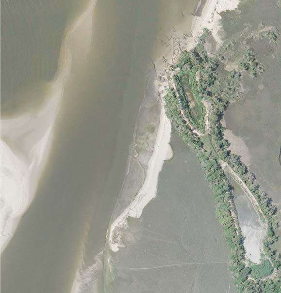
23 Section : Investigation Scope (Athena) was contracted by Olsen Associates, Inc. (Olsen) in January, 24 to collect geotechnical vibracore samples for the Village of Bald Head Island. The purpose of the geotechnical investigation was to characterize sediments in a potential borrow area for beneficial use. The scope of work for the geotechnical sampling project consisted of the collection of seven (7) vibracore samples to a depth of ten () feet below sediment surface. The vibracores were collected from the entrance of Bald Head Creek and were sub-sampled for grain size and carbonate analyses. Section 2: Geological Setting The project site is located adjacent to Bald Head Island in Brunswick County, North Carolina. The site is positioned between the Cape Fear River to the west and the Smith Island backbarrier marsh sequence to the east and north. The Village of Bald Head Island borders the site to the south. A map of the study area has been included as Figure. The feature of interest is a subaqueous and intertidal shoal complex associated with a recurve spit feature located at the entrance to Bald Head Creek. The shoal complex exhibits large scale, flood oriented sand waves and shallow tidal channels. One such tidal channel, located along the eastern extent of the shoal complex, likely represents the natural orientation and position of Bald Head Creek. The setting experiences semidiurnal tides with a mean range of 4. feet (NOAA). Section 3: Site Conditions Athena mobilized to Southport, NC on February 3, 24 in preparation for field sampling. Field sampling commenced and concluded on February 4. Sampling was schedule around a flooding tidal cycle in order to ensure that the sample locations could be accessed via vessel. Water depths at the sample sites averaged 4.6 feet, with a maximum depth of 6.4 feet at BHC-6, and a minimum of 3. feet at BHC-8. The wind direction was approximately miles per hour (mph), with gusts to 2 mph, out of the North. The shallow water depths and predominant wind direction resulted in choppy conditions on top of the shoal complex. The average vibracore penetration and recovery for the Bald Head Creek cores was.4 and 8.6 feet, respectively. A map outlining the Bald Head Creek vibracore locations has been included as Figure 2. Section 4: Field Sampling Methodology Athena utilized our twenty-four (24) foot research vessel as the sampling platform for this investigation. The vessel was equipped with all required US Coast Guard (USCG) safety gear and was operated by a USCG certified Ton Master Captain. A Trimble Differential Global Positioning System (DGPS, sub-meter accuracy) interfaced with HYPACK was utilized for primary navigation. Horizontal coordinates were recorded in North American Datum of 983 (NAD83) State Plane, North Carolina (Zone 32), U.S. Survey Feet. The vessel was immobilized over the desired sample sites using spuds or a triple-point anchor system. Once on station, the coordinates at the current location were verified with the desired station coordinates to ensure accuracy. At this point, a water depth was collected via lead line. 293 Graham Farm Road McClellanville, SC 2948 (843)
 887-38 www.")
24 Figure : Bald Head Creek Site Map Southport Bald Head Creek Project Site Bald Head Island 293 Graham Farm Road McClellanville, SC 2948 (843)
 887-38 www.athenatechnologies.")
25 Figure 2: Bald Head Creek Vibracore Location Map BHC-7 BHC-2 BHC-22 BHC-8 BHC-2 BHC-6 BHC Graham Farm Road McClellanville, SC 2948 (843)
26 A custom-designed and built vibracore system was utilized in order to collect the geotechnical cores. The system consists of a generator with a mechanical vibrator attached via cable. The vibrator is attached directly to a three-inch (3 ) diameter, galvanized sample barrel. The sample barrel was lowered until the bottom of the barrel touched the sediment surface, at which point the barrel was raised until directly above the sediment surface. The vibracore machine was turned on and the sample barrel was allowed to penetrate to a depth of ten () feet below sediment surface, or to refusal. In certain cases (e.g., BHC-6 and BHC-22), the sample barrel was allowed to penetrate to a deeper depth in an attempt to counteract sediment loss during sample barrel retrieval. Once the sample barrel reached the desired depth, the machine was turned off and the sample barrel was retrieved using an electric winch. Once the sample was on deck, the recovered core length was measured to ensure at least eighty (8) percent recovery. Once recovery was verified, the core was then capped, labeled, and cut into five () foot sections. A vibracore summary, outlining penetration, recovery, etc., can be found in Table. The completed vibracore samples were then transported to Athena s facility in McClellanville, SC and were cut open longitudinally. Once opened, one half of the core was transferred to labeled PVC, wrapped in plastic wrap, and inserted into a protective 6-mm plastic liner that was also labeled. The remaining half of the core was then scraped (to show sedimentary structures), logged, and photographed. The core logs were input into gint and forwarded, as draft versions, to Olsen for sample interval determination. Sediment surface elevations were submitted by Olsen to Athena and are represented in National Geodetic Vertical Datum of 929 (NGVD29). At this time, the digital core photographs were processed in order to develop a photo-mosaic image of the core, and those were also forwarded to Olsen. Once the photo-mosaic images and logs for each core were reviewed, Olsen forwarded a list of desired sample intervals to Athena for processing. The core logs, photo-mosaic images, sieve analysis curves, and granularmetric tables for Bald Head Creek have been provided in Appendix A. Section : Laboratory Testing & Results Physical samples were collected from the photographed half of the Bald Head Creek vibracores. The samples were delivered to Terracon Consultants, Inc. (Terracon) in Jacksonville, FL, a USACE certified laboratory. One () composite sample and two (2) discrete samples were collected from each vibracore for a total of twenty-one (2) physical samples. The discrete samples were collected from the top of each core, and from a depth of minus eight (-8) feet relative to NGVD29. The composite sample was comprised of the entire interval between the top of core to minus eight (-8) feet relative to NGVD29. The physical samples were analyzed using the following methods: grain size (ASTM D 422) and carbonate analysis (after Twenhofel & Tyler, 94). The average percent of fine-grained material (i.e., silt and clay passing the # 2 sieve) as reported from the composite samples from the Bald Head Creek cores was.4%, with a maximum value of 2.% from BHC-22. The average grain size for the composite samples was.37 mm (fine sand); however that data is coarsely skewed due to the presence of bioclastic (i.e., shell) material in the physical samples. The actual grain size of the clastic fraction of the physical samples is likely smaller. The average carbonate percentage for the composite samples was.7%, with a maximum value of 2.3% at BHC-9-2. A summary of the laboratory data has been included as Table 2. The average percent of fine-grained material from the top and bottom discrete samples was. and.%, respectively. The average mean grain size for the top and bottom discrete samples 293 Graham Farm Road McClellanville, SC 2948 (843)
 North (y) Water Depth (feet) Penetration (feet) Recovery (feet) Notes")
27 Table : Vibracore Summary Olsen Associates, Inc. Bald Head Creek Geotechnical Investigation Village of Bald Head Island, North Carolina February 24 Boring ID Date Time East (x) North (y) Water Depth (feet) Penetration (feet) Recovery (feet) Notes BHC-6 2/4/4 2:: BHC-7 2/4/4 7:6: BHC-8 2/4/4 8:: BHC-9 2/4/4 :34: Vibrated out first attempt - made second attempt second core. BHC-2 2/4/4 :: BHC-2 2/4/4 9:42: BHC-22 2/4/4 :36: Coordinates were recorded in NAD83, State Plane Coordinate System, North Carolina (Zone 32), US Survey Feet. Project Notes NAD83 - North American Datum of Graham Farm Road, P.O. Box 68 McClellanville, SC 2948 (843)
28 Table 2: Grain Size Data Summary Olsen Associates, Inc. Bald Head Creek Geotechnical Investigation Village of Bald Head Island, North Carolina February 24 Boring ID Sample ID Sample Interval (feet) Mean Grain Size (mm) Percent Passing #2 Sieve (Fines) Percent Carbonate USCS Classification BHC ' SP BHC-6 BHC ' SP Comp ' SP BHC ' SP BHC-7 BHC ' SP Comp ' SP BHC ' SP BHC-8 BHC ' SP Comp-. -.' SP BHC ' SP BHC-9 BHC ' SP Comp ' SP BHC ' SP BHC-2 BHC ' SP Comp ' SP BHC ' SP BHC-2 BHC ' SP Comp-. -.4' SP BHC ' SP BHC-22 BHC ' SP Comp ' SP Percent Carbonate - Analysis was performed according to the following method: Twenhofel and Tyler, 94 USCS - Unified Soil Classification System 293 Graham Farm Road, P. O. Box 68 McClellanville, SC 2948 (843)
29 was.33 and.39 mm, respectively. Average carbonate percentages for the top and bottom samples were 8.4 and 2.4%, respectively. Section 6: Investigation Findings In general, two lithologic units were commonly identified in the geotechnical vibracores collected from the Bald Head Creek project site. The top unit typically consisted of sub-rounded, fine quartz sand, with occasional layers of medium quartz sand and bioclastic (i.e., shell) material. The lower unit was similar to the top, however increased fine grained (i.e., silt and clay) material was noted in this interval. The fine grained material was typically incorporated into the cores via bioturbation, although occasional fine-grained flaser beds and rip-up clasts were also noted from this interval. Four (4) of the cores, BHC-9 through BHC-22, terminated in, or encountered, a silty medium quartz sand with approximately 3 to 4% coarse sand to fine gravel size shell bioclastic material. In most cases, this shell rich interval acted as refusal, however BHC-22 was able to penetrate through this interval and terminated in a bioturbated, fine to medium quartz sand interval with silt percentages greater than %. The silty, shell rich interval was encountered at depths of approximately minus nine (-9) and minus eleven (-) feet relative to NGVD29. Discrete samples collected from six (6) of the Bald Head Creek cores reported carbonate percentages that increased between the top and bottom samples. On average, the carbonate percentages increased by approximately 6%. The exception is in core BHC-22, which reported a decrease in carbonate percentage between the top and bottom discrete samples. Silt percentages also increased slightly between the top and bottom discrete samples, however the increase was minimal and silt percentages in all samples were reported to be well below %. Common marine bivalve and gastropod species identified in the cores consisted of the following: coquina clam (Donax variabilis), eastern oyster (Crassostrea virginica), lightning whelk (Busycon contrarium), and ponderous ark clam (Noetia ponderosa). In general, the bioclastic material in the cores appears to have been transported to the study area and does not necessarily reflect in-situ bioturbation by the abovementioned species. Mud shrimp (Callianassa major) burrow traces, which are commonly lined by fine-grained material, were commonly identified (e.g., BHC-6) in the Bald Head Creek cores and do represent in-situ bioturbation. Mud shrimp are common in relatively high energy marine settings. BHC-22 reported the highest level of bioturbation and, consequently, the highest silt percentage of 2.3%. Section 7: References United States Department of Commerce, National Oceanic and Atmospheric Administration (NOAA), National Ocean Service, Tides & Currents, Station ID: (Southport, NC), (March 4, 24). 293 Graham Farm Road McClellanville, SC 2948 (843)
30 Appendix A Bald Head Creek Core Logs, Photographs, Sieve Analysis Curves, and Granularmetric Reports 293 Graham Farm Road McClellanville, SC 2948 (843)
31 DRILLING LOG DIVISION Olsen Associates, Inc.. PROJECT Village of Bald Head Island Geotechnical Investigation of Bald Head Creek 2. BORING DESIGNATION LOCATION COORDINATES BHC-6 X = 2,34,446 Y =,99 3. DRILLING AGENCY CONTRACTOR FILE NO. 4. NAME OF DRILLER P. McClellan. DIRECTION OF BORING DEG. FROM BEARING VERTICAL VERTICAL INCLINED 6. THICKNESS OF OVERBURDEN 7. DEPTH DRILLED INTO ROCK 8. TOTAL DEPTH OF BORING. Ft.. Ft..7 Ft. Boring Designation BHC-6 INSTALLATION Jacksonville, Florida 9. SIZE AND TYPE OF BIT 3. In.. COORDINATE SYSTEM/DATUM HORIZONTAL North Carolina State Plane NAD 983. MANUFACTURER'S DESIGNATION OF DRILL DISTURBED 2. TOTAL SAMPLES 3. TOTAL NUMBER CORE BOXES 4. ELEVATION GROUND WATER 6.4 Ft. STARTED. DATE BORING : 6. ELEVATION TOP OF BORING -3.9 Ft. 7. TOTAL RECOVERY FOR BORING 9.8 Ft. 8. SIGNATURE AND TITLE OF INSPECTOR A. Freeze SHEET OF SHEETS VERTICAL NGVD 29 AUTO HAMMER MANUAL HAMMER UNDISTURBED (UD) 2 COMPLETED : ELEV. (ft) DEPTH (ft) LEGEND CLASSIFICATION OF MATERIALS Fine to medium quartz SAND, few fine to medium sand size shell, trace silt, poorly graded, subrounded, light brownish gray (2.Y-6/2), (SP). Medium quartz SAND, few medium sand size shell, trace silt, poorly graded, subrounded, light brownish gray (2.Y-6/2), (SP). % REC. BOX OR SAMPLE Comp REMARKS Sample #, Depth =.' -.4' Mean (mm):.28, Phi Sorting:.8 Carbonate: 8.%, Fines (23):.86% (SP) Sample #Comp, Depth =.' - 4.' Mean (mm):.32, Phi Sorting:. Carbonate:.8%, Fines (23):.8% (SP) Fine to medium quartz SAND, trace silt (in burrows), trace fine sand size shell, poorly graded, subrounded, bioturbated, 3.' = Callianassa major burrow trace, light gray (2.Y-7/2), (SP). 2 Sample #2, Depth = 3.7' - 4.' Mean (mm):.2, Phi Sorting:.8 Carbonate: 8.9%, Fines (23):.68% (SP) FLORIDA DEP ROSS BALD HEAD CREEK, NC, FEB. '4.GPJ FL DEP ROSS.GDT 3/3/ SAJ FORM 836 JUN 2 Fine quartz SAND, trace silt (in layers), trace fine sand size shell, poorly graded, subrounded,.3' = layer of medium quartz SAND with little medium to coarse sand size shell, gray (2.Y-6/), (SP). Medium quartz SAND, few medium sand size shell, fine sand in layers, poorly graded, subrounded, bi-directional bedding present, gray (2.Y-6/), (SP). Fine to medium quartz SAND, trace silt (in layers), trace fine sand size shell, poorly graded, subrounded, gray (2.Y-6/), (SP). End of Boring MODIFIED FOR THE FLORIDA DEP JUN 4
32 6 Bald Head Island North Carolina BHC February Scale in Feet Photo Mosaic Image TECHNOLOGIES, INC. 293 Graham Farm Road McClellanville, SC (843)
33 PHI Sieve Sizes Standard Sieve Sizes /4/8-3 / Hydrometer Percent Finer By Weight Percent Coarser By Weight 3 7 SIEVE ANALYSIS BALD HEAD CREEK, NC, FEB. '4.GPJ FL DEP ROSS.GDT 3/3/4 2 Sample BHC-6 # Comments: Gravel Sand Millimeters Coarse Fine Coarse Medium Fine Symbol Elev. (ft) -3.9 USCS % Fines % Organics % Carbonates Median Mean Skew Kurt Sort SP. # # Project Name: Village of Bald Head Island 293 Graham Farm Road McClellanville, SC 2948 ph (843) fax (843) Analysis Date: Analyzed By: Easting (X, ft): Northing (Y, ft):. Horizontal System: Vertical System: Silt and Clay Sample Information CRM Sr. 2,34,446,99 NAD 983 NGVD
34 Granularmetric Report Project Name: Village of Bald Head Island Sample Name: BHC-6 # Analysis Date: Analyzed By: CRM Sr. Easting (ft): Northing (ft): Coordinate System: 293 Graham Farm Road McClellanville, SC 2948 ph (843) fax (843) Elevation (ft): USCS: 2,34,446,99 North Carolina State Plane Munsell: Comments: -3.9 NGVD 29 GRANULARMETRIC REPORT BALD HEAD CREEK, NC, FEB. '4.GPJ FL DEP ROSS.GDT 3/3/4 Dry Weight (g): Wash Weight (g): Pan (g): Sieve Loss (%): Sieve Number Sieve Size (Phi) Sieve Size (Millimeters) Grams 3/4" /8" # # # # # # # # # # # # # # # # Phi 2.9 SP 4.79 Moment Statistics 3.82 Phi Mean Phi.8 Phi Mean mm.28 Phi 2. Sorting.8 Fines (%): # # % Weight Phi 7.3 Organics (%): Carbonates (%): Cum. Grams Skewness -.23 Phi Shells (%): % Passing Sieve Phi 9.8 Kurtosis 4.7
35 PHI Sieve Sizes Standard Sieve Sizes /4/8-3 / Hydrometer Percent Finer By Weight Percent Coarser By Weight 3 7 SIEVE ANALYSIS BALD HEAD CREEK, NC, FEB. '4.GPJ FL DEP ROSS.GDT 3/3/4 2 Sample BHC-6 #Comp Comments: Gravel Sand Millimeters Coarse Fine Coarse Medium Fine Symbol Elev. (ft) -3.9 USCS % Fines % Organics % Carbonates Median Mean Skew Kurt Sort SP. #2 -.8 # Project Name: Village of Bald Head Island 293 Graham Farm Road McClellanville, SC 2948 ph (843) fax (843) Analysis Date: Analyzed By: Easting (X, ft): Northing (Y, ft):. Horizontal System: Vertical System: Silt and Clay Sample Information CRM Sr. 2,34,446,99 NAD 983 NGVD
36 Granularmetric Report Project Name: Village of Bald Head Island Sample Name: BHC-6 #Comp Analysis Date: Analyzed By: CRM Sr. Easting (ft): Northing (ft): Coordinate System: 293 Graham Farm Road McClellanville, SC 2948 ph (843) fax (843) Elevation (ft): USCS: 2,34,446,99 North Carolina State Plane Munsell: Comments: -3.9 NGVD 29 GRANULARMETRIC REPORT BALD HEAD CREEK, NC, FEB. '4.GPJ FL DEP ROSS.GDT 3/3/4 Dry Weight (g): Wash Weight (g): Pan (g): Sieve Loss (%): Sieve Number Sieve Size (Phi) Sieve Size (Millimeters) Grams 3/4" /8" # # # # # # # # # # # # # # # # Phi 2.93 SP 28.6 Moment Statistics Phi Mean Phi.6 Phi Mean mm.32 Phi 2.2 Sorting. Fines (%): #2 -.8 # % Weight Phi 7.8 Organics (%): Carbonates (%): Cum. Grams Skewness -.28 Phi Shells (%): % Passing Sieve Phi Kurtosis 4.8
37 PHI Sieve Sizes Standard Sieve Sizes /4/8-3 / Hydrometer Percent Finer By Weight Percent Coarser By Weight 3 7 SIEVE ANALYSIS BALD HEAD CREEK, NC, FEB. '4.GPJ FL DEP ROSS.GDT 3/3/4 2 Sample BHC-6 #2 Comments: Gravel Sand Millimeters Coarse Fine Coarse Medium Fine Symbol Elev. (ft) -7.6 USCS % Fines % Organics % Carbonates Median Mean Skew Kurt Sort SP. # # Project Name: Village of Bald Head Island 293 Graham Farm Road McClellanville, SC 2948 ph (843) fax (843) Analysis Date: Analyzed By: Easting (X, ft): Northing (Y, ft):. Horizontal System: Vertical System: Silt and Clay Sample Information CRM Sr. 2,34,446,99 NAD 983 NGVD
38 Granularmetric Report Project Name: Village of Bald Head Island Sample Name: BHC-6 #2 Analysis Date: Analyzed By: CRM Sr. Easting (ft): Northing (ft): Coordinate System: 293 Graham Farm Road McClellanville, SC 2948 ph (843) fax (843) Elevation (ft): USCS: 2,34,446,99 North Carolina State Plane Munsell: Comments: -7.6 NGVD 29 GRANULARMETRIC REPORT BALD HEAD CREEK, NC, FEB. '4.GPJ FL DEP ROSS.GDT 3/3/4 Dry Weight (g): Wash Weight (g): Pan (g): Sieve Loss (%): Sieve Number Sieve Size (Phi) Sieve Size (Millimeters) Grams 3/4" /8" # # # # # # # # # # # # # # # # Phi 2.97 SP.78 Moment Statistics 3.86 Phi Mean Phi 2. Phi Mean mm.2 Phi 2.23 Sorting.8 Fines (%): # # % Weight Phi 7.72 Organics (%): Carbonates (%): Cum. Grams Skewness -.9 Phi Shells (%): % Passing Sieve Phi 9.23 Kurtosis.8
39 DRILLING LOG DIVISION Olsen Associates, Inc.. PROJECT Village of Bald Head Island Geotechnical Investigation of Bald Head Creek 2. BORING DESIGNATION LOCATION COORDINATES BHC-7 X = 2,34,66 Y =,49 3. DRILLING AGENCY CONTRACTOR FILE NO. 4. NAME OF DRILLER P. McClellan. DIRECTION OF BORING DEG. FROM BEARING VERTICAL VERTICAL INCLINED 6. THICKNESS OF OVERBURDEN 7. DEPTH DRILLED INTO ROCK 8. TOTAL DEPTH OF BORING. Ft.. Ft.. Ft. Boring Designation BHC-7 INSTALLATION Jacksonville, Florida 9. SIZE AND TYPE OF BIT 3. In.. COORDINATE SYSTEM/DATUM HORIZONTAL North Carolina State Plane NAD 983. MANUFACTURER'S DESIGNATION OF DRILL DISTURBED 2. TOTAL SAMPLES 3. TOTAL NUMBER CORE BOXES 4. ELEVATION GROUND WATER 3.2 Ft. STARTED. DATE BORING :6 6. ELEVATION TOP OF BORING -4. Ft. 7. TOTAL RECOVERY FOR BORING 8.2 Ft. 8. SIGNATURE AND TITLE OF INSPECTOR A. Freeze SHEET OF SHEETS VERTICAL NGVD 29 AUTO HAMMER MANUAL HAMMER UNDISTURBED (UD) 2 COMPLETED :4 FLORIDA DEP ROSS BALD HEAD CREEK, NC, FEB. '4.GPJ FL DEP ROSS.GDT 3/3/4 ELEV. (ft) DEPTH (ft) SAJ FORM 836 JUN 2 LEGEND CLASSIFICATION OF MATERIALS Fine to medium quartz SAND, few fine sand size shell, trace silt, poorly graded, subrounded, bioturbated, light brownish gray (2.Y-6/2), (SP). Fine to medium quartz SAND, few medium sand size shell, trace silt, poorly graded, subrounded, bioturbated, light brownish gray (2.Y-6/2), (SP). Medium quartz SAND, little medium sand size shell, poorly graded, subrounded, light brownish gray (2.Y-6/2), (SP). Fine quartz SAND, trace silt (in burrows), trace fine sand size shell, poorly graded, subrounded, 4.' = burrow trace, gray (2.Y-6/), (SP). Medium quartz SAND, little fine sand size shell, trace silt, poorly graded, subrounded, light brownish gray (2.Y-6/2), (SP). Fine to medium quartz SAND, few medium sand and fine sand size shell (in layers), trace silt (in layers/burrows), poorly graded, subrounded, bioturbated, 6.2' = organic SILT (OL) layer, gray (2.Y-6/), (SP). Fine to medium quartz SAND, trace fine sand size shell, trace silt, poorly graded, subrounded, 6.9' = organic SILT (OL) rip-up, gray (2.Y-6/), (SP). Silty fine to medium quartz SAND, little silt, trace fine sand size shell, subrounded, bioturbated, gray (2.Y-/), (SM). End of Boring MODIFIED FOR THE FLORIDA DEP JUN 4 % REC. BOX OR SAMPLE Comp 2 REMARKS Sample #, Depth =.' -.4' Mean (mm):.28, Phi Sorting:.68 Carbonate: 7.%, Fines (23):.77% (SP) Sample #Comp, Depth =.' - 4.' Mean (mm):.29, Phi Sorting:.86 Carbonate: 8.%, Fines (23):.29% (SP) Sample #2, Depth = 3.6' - 4.' Mean (mm):.4, Phi Sorting:.26 Carbonate: 3.7%, Fines (23):.96% (SP)
40 6 Bald Head Island North Carolina BHC February Scale in Feet Photo Mosaic Image TECHNOLOGIES, INC. 293 Graham Farm Road McClellanville, SC (843)
41 PHI Sieve Sizes Standard Sieve Sizes /4/8-3 / Hydrometer Percent Finer By Weight Percent Coarser By Weight 3 7 SIEVE ANALYSIS BALD HEAD CREEK, NC, FEB. '4.GPJ FL DEP ROSS.GDT 3/3/4 2 Sample BHC-7 # Comments: Gravel Sand Millimeters Coarse Fine Coarse Medium Fine Symbol Elev. (ft) -4. USCS % Fines % Organics % Carbonates Median Mean Skew Kurt Sort SP. # # Project Name: Village of Bald Head Island 293 Graham Farm Road McClellanville, SC 2948 ph (843) fax (843) Analysis Date: Analyzed By: Easting (X, ft): Northing (Y, ft):. Horizontal System: Vertical System: Silt and Clay Sample Information CRM Sr. 2,34,66,49 NAD 983 NGVD
42 Granularmetric Report Project Name: Village of Bald Head Island Sample Name: BHC-7 # Analysis Date: Analyzed By: CRM Sr. Easting (ft): Northing (ft): Coordinate System: 293 Graham Farm Road McClellanville, SC 2948 ph (843) fax (843) Elevation (ft): USCS: 2,34,66,49 North Carolina State Plane Munsell: Comments: -4. NGVD 29 GRANULARMETRIC REPORT BALD HEAD CREEK, NC, FEB. '4.GPJ FL DEP ROSS.GDT 3/3/4 Dry Weight (g): Wash Weight (g): Pan (g): Sieve Loss (%): Sieve Number Sieve Size (Phi) Sieve Size (Millimeters) Grams 3/4" /8" # # # # # # # # # # # # # # # # Phi 2.77 SP Moment Statistics 23.9 Phi Mean Phi.84 Phi Mean mm.28 Phi.99 Sorting.68 Fines (%): # # % Weight Phi 7.7 Organics (%): Carbonates (%): Cum. Grams Skewness -.67 Phi Shells (%): % Passing Sieve Phi 9.4 Kurtosis 8.4
43 PHI Sieve Sizes Standard Sieve Sizes /4/8-3 / Hydrometer Percent Finer By Weight Percent Coarser By Weight 3 7 SIEVE ANALYSIS BALD HEAD CREEK, NC, FEB. '4.GPJ FL DEP ROSS.GDT 3/3/4 2 Sample BHC-7 #Comp Comments: Gravel Sand Millimeters Coarse Fine Coarse Medium Fine Symbol Elev. (ft) -4. USCS % Fines % Organics % Carbonates Median Mean Skew Kurt Sort SP. # # Project Name: Village of Bald Head Island 293 Graham Farm Road McClellanville, SC 2948 ph (843) fax (843) Analysis Date: Analyzed By: Easting (X, ft): Northing (Y, ft):. Horizontal System: Vertical System: Silt and Clay Sample Information CRM Sr. 2,34,66,49 NAD 983 NGVD
44 Granularmetric Report Project Name: Village of Bald Head Island Sample Name: BHC-7 #Comp Analysis Date: Analyzed By: CRM Sr. Easting (ft): Northing (ft): Coordinate System: 293 Graham Farm Road McClellanville, SC 2948 ph (843) fax (843) Elevation (ft): USCS: 2,34,66,49 North Carolina State Plane Munsell: Comments: -4. NGVD 29 GRANULARMETRIC REPORT BALD HEAD CREEK, NC, FEB. '4.GPJ FL DEP ROSS.GDT 3/3/4 Dry Weight (g): Wash Weight (g): Pan (g): Sieve Loss (%): Sieve Number Sieve Size (Phi) Sieve Size (Millimeters) Grams 3/4" /8" # # # # # # # # # # # # # # # # Phi 2.89 SP 2.4 Moment Statistics 9.9 Phi Mean Phi.8 Phi Mean mm.29 Phi 2. Sorting.86 Fines (%): # # % Weight Phi 7. Organics (%): Carbonates (%): Cum. Grams Skewness -.79 Phi Shells (%): % Passing Sieve Phi 9.6 Kurtosis 8.
45 PHI Sieve Sizes Standard Sieve Sizes /4/8-3 / Hydrometer Percent Finer By Weight Percent Coarser By Weight 3 7 SIEVE ANALYSIS BALD HEAD CREEK, NC, FEB. '4.GPJ FL DEP ROSS.GDT 3/3/4 2 Sample BHC-7 #2 Comments: Gravel Sand Millimeters Coarse Fine Coarse Medium Fine Symbol Elev. (ft) -7.6 USCS % Fines % Organics % Carbonates Median Mean Skew Kurt Sort SP. # # Project Name: Village of Bald Head Island 293 Graham Farm Road McClellanville, SC 2948 ph (843) fax (843) Analysis Date: Analyzed By: Easting (X, ft): Northing (Y, ft):. Horizontal System: Vertical System: Silt and Clay Sample Information CRM Sr. 2,34,66,49 NAD 983 NGVD
46 Granularmetric Report Project Name: Village of Bald Head Island Sample Name: BHC-7 #2 Analysis Date: Analyzed By: CRM Sr. Easting (ft): Northing (ft): Coordinate System: 293 Graham Farm Road McClellanville, SC 2948 ph (843) fax (843) Elevation (ft): USCS: 2,34,66,49 North Carolina State Plane Munsell: Comments: -7.6 NGVD 29 GRANULARMETRIC REPORT BALD HEAD CREEK, NC, FEB. '4.GPJ FL DEP ROSS.GDT 3/3/4 Dry Weight (g): Wash Weight (g): Pan (g): Sieve Loss (%): Sieve Number Sieve Size (Phi) Sieve Size (Millimeters) Grams 3/4" /8" # # # # # # # # # # # # # # # # Phi 2.87 SP 2.83 Moment Statistics 9.67 Phi Mean Phi.29 Phi Mean mm.4 Phi.69 Sorting.26 Fines (%): # # % Weight Phi 7.33 Organics (%): Carbonates (%): Cum. Grams Skewness -.92 Phi Shells (%): % Passing Sieve Phi Kurtosis 3.84
47 FLORIDA DEP ROSS BALD HEAD CREEK, NC, FEB. '4.GPJ FL DEP ROSS.GDT 3/3/4 DRILLING LOG DIVISION Olsen Associates, Inc.. PROJECT Village of Bald Head Island Geotechnical Investigation of Bald Head Creek 2. BORING DESIGNATION LOCATION COORDINATES BHC-8 X = 2,34,962 Y =, DRILLING AGENCY CONTRACTOR FILE NO. 4. NAME OF DRILLER P. McClellan. DIRECTION OF BORING DEG. FROM BEARING VERTICAL VERTICAL INCLINED 6. THICKNESS OF OVERBURDEN 7. DEPTH DRILLED INTO ROCK 8. TOTAL DEPTH OF BORING. Ft. ELEV. (ft) DEPTH (ft) SAJ FORM 836 JUN 2 LEGEND. Ft.. Ft. CLASSIFICATION OF MATERIALS Medium quartz SAND, few fine sand size shell, trace silt (in rip-ups), poorly graded, subrounded, light brownish gray (2.Y-6/2), (SP). Fine to medium quartz SAND, trace silt (in burrows), trace fine sand size shell, poorly graded, subrounded, bioturbated, gray (2.Y-6/), (SP). Medium quartz SAND, little medium sand size shell, poorly graded, subrounded, gravel size shell present, ' = fine to medium quartz SAND layer with trace silt, pale yellow (2.Y-7/3), (SP). Fine grading to medium quartz SAND, few medium sand size shell, poorly graded, subrounded, light brownish gray (2.Y-6/2), (SP). Fine to medium quartz SAND, few medium sand size shell, trace silt, poorly graded, subrounded, bioturbated, gray (2.Y-6/), (SP). Medium quartz SAND, little medium to coarse sand size shell, trace gravel size shell, poorly graded, subrounded, grayish brown (2.Y-/2), (SP). End of Boring INSTALLATION Jacksonville, Florida 9. SIZE AND TYPE OF BIT 3. In.. COORDINATE SYSTEM/DATUM HORIZONTAL North Carolina State Plane NAD 983. MANUFACTURER'S DESIGNATION OF DRILL 2. TOTAL SAMPLES 3. TOTAL NUMBER CORE BOXES 4. ELEVATION GROUND WATER 3. Ft. STARTED. DATE BORING : 6. ELEVATION TOP OF BORING -3. Ft. 7. TOTAL RECOVERY FOR BORING A. Freeze Comp 2 DISTURBED 8. SIGNATURE AND TITLE OF INSPECTOR % REC. BOX OR SAMPLE Boring Designation BHC Ft. REMARKS Sample #, Depth =.' -.4' Mean (mm):.37, Phi Sorting:.8 Carbonate: 8.9%, Fines (23):.7% (SP) Sample #Comp, Depth =.' -.' Mean (mm):.32, Phi Sorting:.9 Carbonate: 8.4%, Fines (23):.9% (SP) DRAFT MODIFIED FOR THE FLORIDA DEP JUN 4 Sample #2, Depth = 4.6' -.' Mean (mm):.38, Phi Sorting:.9 Carbonate: 2.4%, Fines (23):.3% (SP) SHEET OF SHEETS VERTICAL NGVD 29 AUTO HAMMER MANUAL HAMMER UNDISTURBED (UD) 2 COMPLETED :3
Appendix D Geotechnical
 USACE JACKSONVIE DISTRICT Appendix D Geotechnical LEE COUNTY GASPARIA SHORE PROTECTION PROJECT 934 REPORT June 216 TABLE OF CONTENTS 1 Background... 1 1.1 Regional Geology... 1 1.2 Local Geology... 2 2
MARTIN COUNTY BOARD OF COUNTY COMMISSIONERS
 MARTIN COUNTY BOARD OF COUNTY COMMISSIONERS 4 S.E. MONTEREY ROAD STUART, FL 34996 DOUG SMITH Commissioner, District ED FIELDING Commissioner, District ANNE SCOTT Commissioner, District 3 SARAH HEARD Commissioner,
Appendix I. Dredged Volume Estimates. Draft Contractor Document: Subject to Continuing Agency Review
 Appendix I Dredged Volume Estimates Draft Contractor Document: Subject to Continuing Agency Review Interoffice Correspondence Date: April 6, 2007 To: L. Bossi (WHI) Copy: S. Thompson (WHI), B. Fidler (NNJ)
DIVISION OF COASTAL MANAGEMENT TO STUDY CURRENT LONG-TERM EROSION RATES ADJACENT TO TERMINAL GROINS
 DIVISION OF COASTAL MANAGEMENT TO STUDY CURRENT LONG-TERM EROSION RATES ADJACENT TO TERMINAL GROINS North Carolina Department of Environmental Quality Division of Coastal Management February 22, 2018 N.
APPENDIX E GEOTECHNICAL INVESTIGATIONS, 2014
 APPENDIX E GEOTECHNICAL INVESTIGATIONS, 14 Submerged Aquatic Vegetation Mitigation EA 2 SECTION 31 32 Geotechnical Data Report for Construction Dredging - Mitigation Prepared by Geotechnical Branch Engineering
DESIGN ENGINEERING ANALYSIS FOR TERMINAL GROIN LENGTH
 APPENDIX F DESIGN ENGINEERING ANALYSIS FOR TERMINAL GROIN LENGTH (Prepared by Olsen Associates, Inc.) DRAFT Environmental Impact Statement Village of Bald Head Island Shoreline Protection Project Brunswick
Plans & Specs Level Offshore Sand Search Investigation, South Peninsula Volusia County, Florida U.S.A.
 Plans & Specs Level Offshore Sand Search Investigation, South Peninsula Volusia County, Florida U.S.A. Randall W. Parkinson, Ph.D., P.G., and Leighann Budde Coastal Technology Corporation Melbourne, FL
Ardaman & Associates, Inc. Geotechnical, Environmental and Materials Consultants
 SUBSURFACE SOIL EXPLORATION DRAINAGE IMPROVEMENTS TO THE HENDRY COUNTY, FLORIDA Ardaman & Associates, Inc. Geotechnical, Environmental and Materials Consultants OFFICES Orlando, 88 S. Orange Avenue, Orlando,
IN SITU SPECIFIC GRAVITY VS GRAIN SIZE: A BETTER METHOD TO ESTIMATE NEW WORK DREDGING PRODUCTION
 IN SITU SPECIFIC GRAVITY VS GRAIN SIZE: A BETTER METHOD TO ESTIMATE NEW WORK DREDGING PRODUCTION Nancy Case O Bourke, PE 1, Gregory L. Hartman, PE 2 and Paul Fuglevand, PE 3 ABSTRACT In-situ specific gravity
ENGINEERING APPROACHES TO SHORELINE PLACEMENT FROM COAST TO COAST
 ENGINEERING APPROACHES TO SHORELINE PLACEMENT FROM COAST TO COAST 237 237 237 217 217 217 200 200 200 0 0 0 163 163 163 131 132 122 80 119 27 252 174.59 83 36 118 110 135 120 112 92 56 62 102 130 Comparing
Amelia Island, Nassau County, FL Marine Geological Field Investigation for Offshore Geologic Model Support
 Amelia Island, Nassau County, FL for Offshore Geologic Model Support BOEM Notice of Scientific Research NA15 001 Submitted to: Bureau of Ocean Energy Management (BOEM) Florida Department of Environmental
Redwood City Harbor, California, Navigation Improvement Feasibility Study. Appendix D. Geotechnical Engineering. DRAFT April 2015
 1 Redwood City Harbor, California, Navigation Improvement Feasibility Study Appendix D Geotechnical Engineering DRAFT April 2015 2 Contents 1 Purposes of Report... 3 2 Background... 3 3 References and
Ardaman & Associates, Inc. Geotechnical, Environmental and Materials Consultants
 SUBSURFACE SOIL EXPLORATION 42-INCH FORCE MAIN REPLACEMENT CHIQUITA BOULEVARD S AND SW 34 TH STREET CAPE CORAL, LEE COUNTY, FLORIDA Ardaman & Associates, Inc. Geotechnical, Environmental and Materials
 Project: ITHACA-TOMPKINS REGIONAL AIRPORT EXPANSION Project Location: ITHACA, NY Project Number: 218-34 Key to Soil Symbols and Terms TERMS DESCRIBING CONSISTENCY OR CONDITION COARSE-GRAINED SOILS (major
Slope Stability Evaluation Ground Anchor Construction Area White Point Landslide San Pedro District Los Angeles, California.
 Slope Stability Evaluation Ground Anchor Construction Area White Point Landslide San Pedro District Los Angeles, California Submitted To: Mr. Gene Edwards City of Los Angeles Department of Public Works
DATA REPORT GEOTECHNICAL INVESTIGATION GALVESTON CRUISE TERMINAL 2 GALVESTON, TEXAS
 DATA REPORT GEOTECHNICAL INVESTIGATION GALVESTON CRUISE TERMINAL 2 GALVESTON, TEXAS SUBMITTED TO PORT OF GALVESTON 123 ROSENBERG AVENUE, 8TH FLOOR GALVESTON, TEXAS 77553 BY HVJ ASSOCIATES, INC. HOUSTON,
DESIGN ENGINEERING ANALYSIS FOR TERMINAL GROIN LENGTH
 APPENDIX I DESIGN ENGINEERING ANALYSIS FOR TERMINAL GROIN LENGTH (Prepared by Olsen Associates, Inc.) Final Environmental Impact Statement Village of Bald Head Island Shoreline Protection Project Brunswick
Appendix E- Geotechnical Investigation Report
 Appendix E- Geotechnical Investigation Report GEOTECHNICAL INVESTIGATION OF OCEAN ISLE BEACH & SHALLOTTE INLET BORROW AREA OCEAN ISLE BEACH SHORELINE MANAGEMENT PROJECT Prepared For: Town of Ocean Isle
Feet. SAND; clayey, fine grained; shells are common; rounded quartz grains. SHELLS; muddy; almost no sand, shells and fragments common
 SAND; clayey, fine grained; shells are common; rounded quartz grains SHELLS; muddy; almost no sand, shells and fragments common SAND; back to medium to fine; has a mottled appearance and looks burrowed;
SAND SEARCH AND FILL MATERIAL QA/QC PLANS FOR BEACH NOURISHMENT PROJECTS IN FLORIDA
 SAND SEARCH AND FILL MATERIAL QA/QC PLANS FOR BEACH NOURISHMENT PROJECTS IN FLORIDA Jennifer L. Koch (Coastal Geologist), Beth M. Forrest (Coastal Geologist) and Robert M. Brantly (Program Administrator)
M E M O R A N D U M. Mr. Jonathan K. Thrasher, P.E., Mr. Ian Kinnear, P.E. (FL) PSI
 PSI") M E M O R A N D U M TO: FROM: Mr. Mark Schilling Gulf Interstate Engineering Mr. Jonathan K. Thrasher, P.E., Mr. Ian Kinnear, P.E. (FL) PSI DATE: November 11, 2014 RE: Summary of Findings Geotechnical
M E M O R A N D U M TO: FROM: Mr. Mark Schilling Gulf Interstate Engineering Mr. Jonathan K. Thrasher, P.E., Mr. Ian Kinnear, P.E. (FL) PSI DATE: November 11, 2014 RE: Summary of Findings Geotechnical
3. MARINE HABITAT RESTORATION
 Feasibility Study for Restoration of Titlow Lagoon Fish Passage South Puget Sound Salmon Enhancement Group 3. MARINE HABITAT RESTORATION Marine habitat restoration at Titlow Park could include restoration
APPENDIX 1 SCOPE OF SERVICES (Digital Copy Only)
") APPENDIX 1 SCOPE OF SERVICES (Digital Copy Only) SCOPE OF PROFFESIONAL SERVICES OUTER BANKS, NORTH CAROLINA COMPREHENSIVE SAND SEARCH PERMITTING AND ENGINERERING SUPPORT FOR BEACH NOURISHMENT In order
APPENDIX 1 SCOPE OF SERVICES (Digital Copy Only) SCOPE OF PROFFESIONAL SERVICES OUTER BANKS, NORTH CAROLINA COMPREHENSIVE SAND SEARCH PERMITTING AND ENGINERERING SUPPORT FOR BEACH NOURISHMENT In order
Appendix E. Phase 2A Geotechnical Data
 Appendix E Phase 2A Geotechnical Data Appendix E1 Geotechnical Testing of Sediment ApPENDIX El. GEOTECHNICAL TESTING OF SEDIMENT (Modified from Exponent, 20Q1c) E.I Introduction This appendix presents
Estimated Sediment Volume: Bridge Street Dam Impoundment, Royal River, Yarmouth, Maine
 University of Southern Maine USM Digital Commons Publications Casco Bay Estuary Partnership (CBEP) 2015 Estimated Sediment Volume: Bridge Street Dam Impoundment, Royal River, Yarmouth, Maine Stantec Follow
ST. LUCIE COUNTY, FLORIDA
 ST. LUCIE COUNTY, FLORIDA COASTAL STORM RISK MANAGEMENT PROJECT DRAFT INTEGRATED FEASIBILITY STUDY AND ENVIRONMENTAL ASSESSMENT APPENDIX D Geotechnical APRIL 2016 TABLE OF CONTENTS 1 Background... 3 1.1
B-1 BORE LOCATION PLAN. EXHIBIT Drawn By: 115G BROOKS VETERINARY CLINIC CITY BASE LANDING AND GOLIAD ROAD SAN ANTONIO, TEXAS.
 N B-1 SYMBOLS: Exploratory Boring Location Project Mngr: BORE LOCATION PLAN Project No. GK EXHIBIT Drawn By: 115G1063.02 GK Scale: Checked By: 1045 Central Parkway North, Suite 103 San Antonio, Texas 78232
Coring and sediment sampling
 Coring and sampling Principle: In order to ground-truth geophysical data, it is necessary to obtain a sample of the seabed. There are two main techniques available for sampling unconsolidated s : (1) seabed
Civil Engineering, Surveying and Environmental Consulting WASP0059.ltr.JLS.Mich Ave Bridge Geotech.docx
 2365 Haggerty Road South * Canton, Michigan 48188 P: 734-397-3100 * F: 734-397-3131 * www.manniksmithgroup.com August 29, 2012 Mr. Richard Kent Washtenaw County Parks and Recreation Commission 2330 Platt
Feet. Cape May Core #51 Start depth: 240 ft Stop depth: 245 ft Recovery (ft): 5.1 ft Date: 3/21/94 Described by: JVB, KGM, CL. 5.
: 5.1 ft Date: 3/21/94 Described by: JVB, KGM, CL. 5.") SAND; medium to fine sand with abundant silt, homogenous slightly mottled appearance; mica on outside, mostly quartz; few darks; peat layer.9 - ft; cnv - same as above; the last few cores are all the same;
SAND; medium to fine sand with abundant silt, homogenous slightly mottled appearance; mica on outside, mostly quartz; few darks; peat layer.9 - ft; cnv - same as above; the last few cores are all the same;
Geotechnical Engineering Report
 Geotechnical Engineering Report Turner Turnpike Widening Bridge B Bridge Crossing: South 257 th West Avenue Creek County, Oklahoma June 1, 2016 Terracon Project No. 04155197 Prepared for: Garver, LLC Tulsa,
Field Exploration. March 31, J-U-B ENGINEERS, Inc. 115 Northstar Avenue Twin Falls, Idaho Attn: Mr. Tracy Ahrens, P. E. E:
 March 31, 201 11 Northstar Avenue 83301 Attn: Mr. Tracy Ahrens, P. E. E: taa@jub.com Re: Geotechnical Data Report Preliminary Phase 1 Field Exploration Revision No. 1 Proposed Rapid Infiltration Basin
ST. JOHNS COUNTY, FLORIDA
 ST. JOHNS COUNTY, FLORIDA South onte Vedra Beach, Vilano Beach, and Summer Haven Reaches COASTAL STORM RISK MANAGEMENT ROJECT DRAFT INTEGRATED FEASIBILITY STUDY AND ENVIRONMENTAL ASSESSMENT AENDIX D Geotechnical
GEOTECHNICAL INVESTIGATION REPORT
 GEOTECHNICAL INVESTIGATION REPORT SOIL INVESTIGATION REPORT FOR STATIC TEST FACILITY FOR PROPELLANTS AT BDL, IBRAHIMPATNAM. Graphics Designers, M/s Architecture & Engineering 859, Banjara Avenue, Consultancy
B-1 SURFACE ELEVATION
 5A 5B LOGGED BY El. S. Bhangoo DRILLING CONTRACTOR Pitcher Drilling DRILLING METHOD Rotary Wash BEGIN DATE 12-14-12 SAMPLER TYPE(S) AND SIZE(S) (ID) SPT, MC BOREHOLE BACKFILL AND COMPLETION COMPLETION
Potential Upland Sand Sources to Support Southwest Florida Beach Projects
 1 of 21 Potential Upland Sand Sources to Support Southwest Florida Beach Projects Depending on project size and timeline, upland sand sources (mines) may be viable for beach construction projects in southwest
7. STREAMBED TEXTURE ANALYSIS
 Geomorphology 7. Streambed Texture Analysis 7. STREAMBED TEXTURE ANALYSIS 50 Points The purpose of this exercise is to analyze the size characteristics of the sediment samples collected in the field. We
GEOTECHNICAL TESTING OF SEDIMENT
 ApPENDIX El. GEOTECHNICAL TESTING OF SEDIMENT (Modified from Exponent, 20Q1c) E.I Introduction This appendix presents information regarding geotechnical testing performed in 2000 on sediments in Onondaga
Feet CLAY; silty, greenish gray and clayey fine sand; Color: 5Y 3/1
 -. CLAY; silty, greenish gray and clayey fine sand; Color: Y /. -. SAND; fine-medium, clayey, with sandy clay layers; very abundant broken thin, tiny shells; shell hash at several horizons, heavily burrowed;
Sunset Harbour / Huntington Harbour Maintenance Dredging and Waterline Installation Project. CMANC 21 January 2016
 Sunset Harbour / Huntington Harbour Maintenance Dredging and Waterline Installation Project CMANC 21 January 2016 County of Orange Footprint Huntington Harbour Operational and Dredging Cost Sharing Agreements
CITY OF CAPE CORAL NORTH 2 UTILITIES EXTENSION PROJECT CONTRACT 3
 GEOTECHNICAL REPORT CITY OF CAPE CORAL NORTH UTILITIES EXTENSION PROJECT CONTRACT City of Cape Coral Procurement Division Cultural Park Boulevard, nd Floor Cape Coral, FL ISSUED FOR BID VOLUME of GEOTECHNICAL
10. GEOTECHNICAL EXPLORATION PROGRAM
 Geotechnical site investigations should be conducted in multiple phases to obtain data for use during the planning and design of the tunnel system. Geotechnical investigations typically are performed in
Chapter 7 Mudflow Analysis
 Chapter 7 Mudflow Analysis 7.0 Introduction This chapter provides information on the potential and magnitude of mud floods and mudflows that may develop in Aspen due to rainfall events, snowmelt, or rain
 Photo 1 - Southerly view across 2700 parking lot toward existing building. Multi-residential building borders western side of property in upper right of view. Photo 2 - Southerly view across 2750 parking
Pierce County Department of Planning and Land Services Development Engineering Section
 Page 1 of 7 Pierce County Department of Planning and Land Services Development Engineering Section PROJECT NAME: DATE: APPLICATION NO.: PCDE NO.: LANDSLIDE HAZARD AREA (LHA) GEOLOGICAL ASSESSMENT REPORT
Mound Study Project Cape Fear, North Carolina Report Summary VIMS Reports: CHSD to CHSD EHI Project No
 Mound Study Project Cape Fear, North Carolina Report Summary VIMS Reports: CHSD-2003-02 to CHSD-2003-06 EHI Project No. 6000.21 February 2003 Final VIMS Report CHSD-2003-01 Prepared for Evans-Hamilton,
PRELIMINARY GEOTECHNICAL ENGINEERING REPORT. Proposed Re-Development 44 Old Worcester Road Charlton, Massachusetts. Prepared For:
 PRELIMINARY GEOTECHNICAL ENGINEERING REPORT Proposed Re-Development 44 Old Worcester Road Charlton, Massachusetts Prepared For: Meridian Associates, Inc. 500 Cummings Center, Suite 5950 Beverly, Massachusetts
PROFESSIONAL SERVICES DESCRIPTION FOR THE POSITION OF:
 PROFESSIONAL SERVICES DESCRIPTION FOR THE POSITION OF: Paulsboro Marine Terminal Sediment and Benthic Sampling and Characterization Plan Addendum No. 1 SUBMISSION DEADLINE: May 27, 2009 at 11:00 A.M. FAIR
PLATE 6 FEB G r o v e l a n d F l o o d w a l l - B o r e h o l e M a p. Legend. Groveland Floodwall Boreholes. Contour Lines.
 611 6 Defau FALS conto Conto DPLV lt Eurs20 01_to 3po Defau FALS conto Conto DPLV lt Eurs20 01_to 4po 612 Conto DPLV conto Defau FALS 01_to urs20 Elt po 5 Conto DPLV conto Defau FALS 01_to urs15 Elt po
GEOTECHNICAL REPORT. Matanuska-Susitna Borough. Parks Highway Connections Museum Drive. Matanuska-Susitna Borough, Alaska.
 Matanuska-Susitna Borough GEOTECHNICAL REPORT Parks Highway Connections Museum Drive Matanuska-Susitna Borough, Alaska March 2, 20 Prepared By: John Thornley, PE Geotechnical Engineer 333 Arctic Blvd.,
SUPPLEMENTARY INVESTIGATION AND LABORATORY TESTING Aggregate Resource Evaluation Proposed Bernand Quarry San Diego County, California
 October 3, 2 Mr. Mark San Agustin Project No. 28-- Home Land Investments Document No. -92 2239 Curlew Street San Diego, CA 92 SUBJECT: SUPPLEMENTARY INVESTIGATION AND LABORATORY TESTING Aggregate Resource
Chapter 7 Mudflow Analysis
 Chapter 7 Mudflow Analysis 7.0 Introduction This chapter provides information on the potential and magnitude of mud floods and mudflows that may develop in Aspen due to rainfall events, snowmelt, or rain
Correlation of gravel deposits from trenching project on Alder Creek fluvial terrace near Point Arena, California
 Correlation of gravel deposits from trenching project on Alder Creek fluvial terrace near Point Arena, California Aletha Lee Department of Geology and Geography, West Virginia University, White Hall, Morgantown,
Ardaman & Associates, Inc. Geotechnical, Environmental and Materials Consultants
 SUBSURFACE SOIL EXPLORATION ANALYSIS AND RECOMMENDATIONS LELY AREA STORMWATER IMPROVEMENT PROJECT (LASIP) COUNTY BARN ROAD AND WING SOUTH CHANNELS NAPLES, COLLIER CO., FLORIDA Ardaman & Associates, Inc.
Lower 8.3 Miles of the Lower Passaic River Operable Unit 2 Presentation to The Passaic River Community Advisory Group. September 14, 2017
 Lower 8.3 Miles of the Lower Passaic River Operable Unit 2 Presentation to The Passaic River Community Advisory Group September 14, 2017 Agenda Pre-Design Investigation (PDI) Status Geophysical, Bathymetric,
UPPER COSUMNES RIVER FLOOD MAPPING
 UPPER COSUMNES RIVER FLOOD MAPPING DRAFT BASIC DATA NARRATIVE FLOOD INSURANCE STUDY SACRAMENTO COUTY, CALIFORNIA Community No. 060262 November 2008 Prepared By: CIVIL ENGINEERING SOLUTIONS, INC. 1325 Howe
ENGINEERING WITH NATURE: NEARSHORE BERM PLACEMENTS AT FORT MYERS BEACH AND PERDIDO KEY, FLORIDA, USA
 1 ENGINEERING WITH NATURE: NEARSHORE BERM PLACEMENTS AT FORT MYERS BEACH AND PERDIDO KEY, FLORIDA, USA KATHERINE E. BRUTSCHÉ 1, PING WANG 2, JULIE D. ROSATI 1, CHERYL E. POLLOCK 1 1. U.S. Army Engineer
EAGLES NEST AND PIASA ISLANDS
 EAGLES NEST AND PIASA ISLANDS HABITAT REHABILITATION AND ENHANCEMENT PROJECT MADISON AND JERSEY COUNTIES, ILLINOIS ENVIRONMENTAL MANAGEMENT PROGRAM ST. LOUIS DISTRICT FACT SHEET I. LOCATION The proposed
FILL SUITABILITY CHARACTERIZATION OF A COMPLEX COASTAL AREA: DARE COUNTY, NORTH CAROLINA
 FILL SUITABILITY CHARACTERIZATION OF A COMPLEX COASTAL AREA: DARE COUNTY, NORTH CAROLINA Donald K. Stauble 1, William Birkemeier, Michael F. Forte and William A. Dennis 3 ABSTRACT As part of the design
A SEDIMENT BUDGET ANALYSIS AND MANAGEMENT STRATEGY FOR FORT PIERCE INLET, FL
 A SEDIMENT BUDGET ANALYSIS AND MANAGEMENT STRATEGY FOR FORT PIERCE INLET, FL By Elba Rodriguez and Robert G. Dean Department of Civil and Coastal Engineering University of Florida Gainesville, FL 32611,
Date: April 2, 2014 Project No.: Prepared For: Mr. Adam Kates CLASSIC COMMUNITIES 1068 E. Meadow Circle Palo Alto, California 94303
 City of Newark - 36120 Ruschin Drive Project Draft Initial Study/Mitigated Negative Declaration Appendix C: Geologic Information FirstCarbon Solutions H:\Client (PN-JN)\4554\45540001\ISMND\45540001 36120
Tom Blackman Project Lead. Mékell Mikell Communications Representative
 Sediment Cleanup Middle River Complex, 2016-17 Season 1 Project Photo Tour Updated November 15, 2016 Tom Blackman Project Lead Mékell Mikell Communications Representative 1 Sediment Cleanup - Season 1
APPENDIX C HYDROGEOLOGIC INVESTIGATION
 Figure B-5.7 Figure B-5.8 Preliminary Geotechnical and Environmental Report Appendix C Hydrogeologic Investigation APPENDIX C HYDROGEOLOGIC INVESTIGATION December 21, 2011 WESTSIDE SUBWAY EXTENSION PROJECT
Project No: 68R3056 Client: City of Frederick Project: RFQ 14-H Future North Side Water Tank City/State: 7516 Hayward Road, Frederick, MD
 Boring: SB-1 (1 of 1) Moist, brown to orange brown CLAY and SILT, trace sand with fine weathered rock fragments. POSSIBLE FILL. Dry, orange brown sandy SILT trace clay (SM-ML). RESIDUAL SOIL : Not Surveyed
Appendix G.18 Hatch Report Pacific NorthWest LNG Lelu Island LNG Potential Impacts of the Marine Structures on the Hydrodynamics and Sedimentation
 Appendix G.18 Hatch Report Pacific NorthWest LNG Lelu Island LNG Potential Impacts of the Marine Structures on the Hydrodynamics and Sedimentation Patterns Project Memo H345670 To: Capt. David Kyle From:
Report of Preliminary Geotechnical Investigation for Ponds
 Florida Department of TRANSPORTATION Report of Preliminary Geotechnical Investigation for Ponds Malabar Road (SR 514) PD&E Study From East of Babcock Street (SR 507) to US 1 Brevard County, Florida FPID:
THIN-LAYER PLACEMENT OF DREDGE MATERIAL FOR MARSH NOURISHMENT, RESOTRATION, AND RESPONSE TO SEA LEVEL RISE
 THIN-LAYER PLACEMENT OF DREDGE MATERIAL FOR MARSH NOURISHMENT, RESOTRATION, AND RESPONSE TO SEA LEVEL RISE Case studies and lesson learned regarding thin-layer deposition projects in Delaware, New Jersey,
AN ARCHAEOLOGICAL SURVEY FOR THE EASTHAM STATE PRISON FARM UNIT PROJECT IN HOUSTON COUNTY TEXAS
 AN ARCHAEOLOGICAL SURVEY FOR THE EASTHAM STATE PRISON FARM UNIT PROJECT IN HOUSTON COUNTY TEXAS Antiquities Permit 5693 By William E. Moore and Edward P. Baxter Brazos Valley Research Associates Contract
STRUCTURAL STABILITY ASSESSMENT
 STRUCTURAL STABILITY ASSESSMENT CFR 257.73(d) Bottom Ash Pond Complex Cardinal Plant Brilliant, Ohio October, 2016 Prepared for: Cardinal Operating Company Cardinal Plant Brilliant, Ohio Prepared by: Geotechnical
Report of Preliminary Geotechnical Exploration. CSO-012 Sewer Separation Cincinnati, Hamilton County, Ohio. February, 2011
 11242843_GeoTech_Preliminary - Feburary 2011_1/40 Report of Preliminary Geotechnical Exploration CSO-012 Sewer Separation Cincinnati, Hamilton County, Ohio February, 2011 11242843_GeoTech_Preliminary -
Geotechnical Engineering Report
 Geotechnical Engineering Report Turner Turnpike Widening Bridge D Bridge Crossing: South 209 th West Avenue Creek County, Oklahoma June 1, 2016 Terracon Project No. 04155197 Prepared for: Garver, LLC Tulsa,
TIERRA. Florida License No Florida License No
 March 9, 208 TIERRA AECOM 7650 West Courtney Campbell Cswy Tampa, FL 33607 Attn: RE: Mr. Edgar Figueroa, P.E. Geotechnical Engineering Services Report Purchase Order No.: 9532 AECOM Project Number: 6055499
Appendix G.19 Hatch Report Pacific NorthWest LNG Lelu Island LNG Maintenance Dredging at the Materials Offloading Facility
 Appendix G.19 Hatch Report Pacific NorthWest LNG Lelu Island LNG Maintenance Dredging at the Materials Offloading Facility Project Memo H345670 To: Capt. David Kyle From: O. Sayao/L. Absalonsen December
SAVANNAH HARBOR EXPANSION BANK EROSION STUDY UPDATE
 CESAS-EN-GS SAVANNAH HARBOR EXPANSION BANK EROSION STUDY UPDATE GEOTECHNICAL AND HTRW BRANCH SOILS SECTION CITY FRONT, BIGHT SECTION, FORT PULASKI & NORTH TYBEE ISLAND GEORGIA 23 June 2011 CESAW-TS-EG
COASTAL PLANNING & ENGINEERING OF NORTH CAROLINA, INC
 4038 MASONBORO LOOP ROAD, WILMINGTON, NC 28409 910-791-9494 PHONE 910-791-4129 FAX July 15, 2014 David W. Cooke Regional Supervisor for Resource Evaluation Bureau of Ocean Energy Management Gulf of Mexico
H.1 SUMMARY OF SUBSURFACE STRATIGRAPHY AND MATERIAL PROPERTIES (DATA PACKAGE)
") DRAFT ONONDAGA LAKE CAPPING AND DREDGE AREA AND DEPTH INITIAL DESIGN SUBMITTAL H.1 SUMMARY OF SUBSURFACE STRATIGRAPHY AND MATERIAL PROPERTIES (DATA PACKAGE) Parsons P:\Honeywell -SYR\444576 2008 Capping\09
DRAFT ONONDAGA LAKE CAPPING AND DREDGE AREA AND DEPTH INITIAL DESIGN SUBMITTAL H.1 SUMMARY OF SUBSURFACE STRATIGRAPHY AND MATERIAL PROPERTIES (DATA PACKAGE) Parsons P:\Honeywell -SYR\444576 2008 Capping\09
Seagrass Transplantation & Environmental & Marine Consulting Services, Inc. Drew Campbell, Vice President & Lead Scientst.
 Indian River Lagoon Symposium Seagrass Transplantation & Project Considerations Environmental & Marine Consulting Services, Inc. Drew Campbell, Vice President & Lead Scientst March 26 th, 2013 Regulatory
Geotechnical Engineering Report
 Geotechnical Engineering Report Richland Creek Trunk Sewer Greenville, South Carolina March 31, 2014 Terracon Project No. 86145008 Prepared for: Renewable Water Resources Greenville, South Carolina Prepared
Safe bearing capacity evaluation of the bridge site along Syafrubesi-Rasuwagadhi road, Central Nepal
 Bulletin of the Department of Geology Bulletin of the Department of Geology, Tribhuvan University, Kathmandu, Nepal, Vol. 12, 2009, pp. 95 100 Safe bearing capacity evaluation of the bridge site along
USE OF GEOPHYSICAL SURVEYS FOR FILL CHARACTERIZATION AND QUANTITY ESTIMATION AT BROWNFIELD SITES A CASE HISTORY. Abstract
 USE OF GEOPHYSICAL SURVEYS FOR FILL CHARACTERIZATION AND QUANTITY ESTIMATION AT BROWNFIELD SITES A CASE HISTORY John A. Mundell, Mundell & Associates, Inc., Indianapolis, IN Gregory B. Byer, Mundell &
Geotechnical Data Report
 Geotechnical Data Report Downtown Greenville Future Conveyance Study December 1, 2015 Terracon Project No. 86155032 Prepared for: Prepared by: Terracon Consultants, Inc. December 1, 2015 561 Mauldin Road
CE 240 Soil Mechanics & Foundations Lecture 3.2. Engineering Classification of Soil (AASHTO and USCS) (Das, Ch. 4)
 (Das, Ch. 4)") CE 240 Soil Mechanics & Foundations Lecture 3.2 Engineering Classification of Soil (AASHTO and USCS) (Das, Ch. 4) Outline of this Lecture 1. Particle distribution and Atterberg Limits 2. Soil classification
CE 240 Soil Mechanics & Foundations Lecture 3.2 Engineering Classification of Soil (AASHTO and USCS) (Das, Ch. 4) Outline of this Lecture 1. Particle distribution and Atterberg Limits 2. Soil classification
POST CABLE INSTALLATION THERMAL MONITORING PROGRAM LONG ISLAND REPLACEMENT CABLE PROJECT NORWALK, CT OSI JOB# 08ES069
 28 July 2009 Mark D. Driscoll, M.S. Senior Water Resources Scientist. 888 Worcester Street, Suite 2 Wellesley, MA 02482 SUBJECT: FINAL REPORT POST CABLE INSTALLATION THERMAL MONITORING PROGRAM LONG ISLAND
 SOIL CLASSIFICATION CHART COARSE-GRAINED SOILS MORE THAN 50% RETAINED ON NO.200 SIEVE FINE-GRAINED SOILS 50% OR MORE PASSES THE NO.200 SIEVE PRIMARY DIVISIONS GRAVELS MORE THAN 50% OF COARSE FRACTION RETAINED
ATTACHMENT A WEAVER BOTTOMS SEDIMENT BASIN MAINTENANCE PROJECT PROJECT REPORT SUMMARY (APRIL 7, 2014)
") ATTACHMENT A WEAVER BOTTOMS SEDIMENT BASIN MAINTENANCE PROJECT PROJECT REPORT SUMMARY (APRIL 7, 2014) PRE-PROJECT DREDGE MATERIAL SEDIMENT CORE AND BASELINE CONTAMINANT ANALYSIS PREPARED BY BRAUN INTERTEC
ATTACHMENT A WEAVER BOTTOMS SEDIMENT BASIN MAINTENANCE PROJECT PROJECT REPORT SUMMARY (APRIL 7, 2014) PRE-PROJECT DREDGE MATERIAL SEDIMENT CORE AND BASELINE CONTAMINANT ANALYSIS PREPARED BY BRAUN INTERTEC
Boundary Expansion of Thunder Bay National Marine Sanctuary; Correction and Expansion of Fagatele Bay National Marine
 This document is scheduled to be published in the Federal Register on 12/23/2015 and available online at http://federalregister.gov/a/2015-32265, and on FDsys.gov Billing Code 3510-NK-P DEPARTMENT OF COMMERCE
Geotechnical Engineering Report
 Geotechnical Engineering Report Turner Turnpike Widening Polecat Creek Bridge (Bridge A) June 1, 2016 Terracon Project No. 04155197 Prepared for: Garver, LLC Prepared by: Terracon Consultants, Inc. TABLE
September 21, 2004 GeoInsight Project
 GeoInsight, Inc. GeoInsight, Inc. GeoInsight, Inc. 75 Gilcreast Road, Suite 210 319 Littleton Road, Suite 105 Corporate Ten Center Londonderry, NH 03053-3566 Westford, MA 01886 1781 Highland Avenue, Suite
June 9, R. D. Cook, P.Eng. Soils Engineer Special Services Western Region PUBLIC WORKS CANADA WESTERN REGION REPORT ON
 PUBLIC WORKS CANADA WESTERN REGION REPORT ON GEOTECHNICAL INVESTIGATION PROPOSED MARTIN RIVER BRIDGE MILE 306.7 MACKENZIE HIGHWAY Submitted by : R. D. Cook, P.Eng. Soils Engineer Special Services Western
Regional Sediment Management
 Regional Sediment Management Linda S. Lillycrop Program Manager Coastal Engineer US Army Engineer Research and Development Center Coastal and Hydraulics Laboratory Q AVG Coastal Resilience: The Environmental,
Geology for Engineers Sediment Size Distribution, Sedimentary Environments, and Stream Transport
 Name 89.325 Geology for Engineers Sediment Size Distribution, Sedimentary Environments, and Stream Transport I. Introduction The study of sediments is concerned with 1. the physical conditions of a sediment,
Paleo Lab #4 - Sedimentary Environments
 Paleo Lab #4 - Sedimentary Environments page - 1. CHARACTERISTICS OF SEDIMENT Grain size and grain shape: The sizes and shapes of sedimentary particles (grains) are modified considerably during their transportation
Limited Geotechnical Engineering Evaluation Classroom Additions Albany County Campus Laramie, Wyoming
 Limited Geotechnical Engineering Evaluation Classroom Additions Albany County Campus 2300 Missile Drive, Cheyenne, Wyoming 82001 Phone 307-635-0222 www.stratageotech.com Limited Geotechnical Engineering
GZA GeoEnvironmental, Inc.
 GZA BORING NO.: GZ-1 SHEET: 1 of 1 PROJECT NO: 9.223. Drilling Co.: Geologic Type of Rig: Skid Boring Location: See Plan H. Datum: See Plan Rig Model: Mudline : Foreman: Ray Eastwood CME -.8 Final Boring
ENGINEER S CERTIFICATION OF FAULT AREA DEMONSTRATION (40 CFR )
") PLATTE RIVER POWER AUTHORITY RAWHIDE ENERGY STATION BOTTOM ASH TRANSFER (BAT) IMPOUNDMENTS LARIMER COUNTY, CO ENGINEER S CERTIFICATION OF FAULT AREA DEMONSTRATION (40 CFR 257.62) FOR COAL COMBUSTION RESIDUALS
PLATTE RIVER POWER AUTHORITY RAWHIDE ENERGY STATION BOTTOM ASH TRANSFER (BAT) IMPOUNDMENTS LARIMER COUNTY, CO ENGINEER S CERTIFICATION OF FAULT AREA DEMONSTRATION (40 CFR 257.62) FOR COAL COMBUSTION RESIDUALS
RECENT SEDIMENTS OF CALIFORNIA PART A. INTRODUCTION AND GRAIN SIZE ANALYSIS HYDRAULIC ENGINEERING LABORATORY COLLEGE OF ENGINEERING C.
 HEL-2-19! 9* I 1 f RECENT SEDIMENTS OF BOLINAS BAY CALIFORNIA PART A. INTRODUCTION AND GRAIN SIZE ANALYSIS by C. ISSELHARDT L. OSUCH RWILDE. HYDRAULIC ENGINEERING LABORATORY COLLEGE OF ENGINEERING UNIVERSITY
EAST PASS UP-DATE SUMMARY OF FINDINGS REPORT and INLET MANAGEMENT IMPLEMENTATION PLAN
 EAST PASS 2013 UP-DATE SUMMARY OF FINDINGS REPORT and INLET MANAGEMENT IMPLEMENTATION PLAN Introduction On June 8, 2000, the Florida Department of Environmental Protection adopted the East Pass Inlet Management
Estimating Remedial Volumes for a GLLA Project on the Milwaukee River
 Estimating Remedial Volumes for a GLLA Project on the Milwaukee River Mike Ciarlo, Jamie Beaver, Mike Powell, Jason Byler EA Engineering, Science, and Technology, Inc. Marsha Burzynski, William Fitzpatrick
Lake Worth Lagoon Hydrographic Survey Report
 C-51 Canal Sediment Trap Lake Worth Lagoon Hydrographic Survey Report July 11, 2013 South Florida Water Management District 3301 Gun Club Road West Palm Beach, Florida 33406 Table of Contents Background...
Highland Lake Bathymetric Survey
 Highland Lake Bathymetric Survey Final Report, Prepared For: The Town of Highland Lake 612 Lakeshore Drive Oneonta, AL 35121 Prepared By: Tetra Tech 2110 Powers Ferry Road SE Suite 202 Atlanta, GA 30339