Photovoltaic Devices. Content
|
|
|
- Harry Harrell
- 6 years ago
- Views:
Transcription


1 Photovoltaic Devices EPFL IMT - PVLab Highlights in Microtechnology, 2014 Content Applications overviews Brief history Basics of photovoltaics (PV) Physical principle and performance limits Multi-junction devices PV technologies Si thin-film technologies Module technology Photodiodes and microsystems 2 1
 the photovoltaic effect while experimenting (in his father s laboratory - Antoine-César Becquerel s")

2 Applications, History and Motivation Photovoltaic effect Edmund Becquerel, the French experimental physicist, discovered (in 1839, at the age of 19) the photovoltaic effect while experimenting (in his father s laboratory - Antoine-César Becquerel s laboratory) with an electrolytic cell made up of two metal electrodes placed in an electricityconducting solution--generation increased when exposed to light. E. Becquerel, 'On electron effects under the influence of solar radiation.' Comptes Rendus 9,
 1888 : Edward Weston receives first US patent for \"solar cell\" 1905 : Albert")
3 Brief history 1839 : Discovery of photovoltaic effect by Becquerel 1877 : Observation of the photovoltaic effect in solid selenium by W.G. Adams and R.E. Day 1883 : Description of the first solar cells made from selenium wafers by Charles Fritts (with efficiency < 1%) 1888 : Edward Weston receives first US patent for "solar cell" 1905 : Albert Einstein s paper on the photoelectric effect 1916 : Experimental proof of Einstein s theory on photoelectric effect by Robert Millikan 1922 : Einstein wins Nobel prize for 1904 paper on photoelectric effect 1941 : First silicon photovoltaic cell developed by Ohl 1954 : First high-power silicon PV cell (achieving 6%) by Bell Labs. The New York Times forecasts that solar cells will eventually lead to a source of "limitless energy of the sun" : US Vanguard I space satellite powered by a PV array 1963 : Viable photovoltaic module of silicon solar cells produced by Sharp Japan installs a 242-watt PV array on a lighthouse, the world's largest array at that time. 1970s : PV costs driven down by 80%, allowing for applications such as offshore navigation warning lights and horns lighthouses, railroad crossings, and remote use where utility-grid connections are too costly; start of mass production : World-wide PV production > 30 GW/year Approx. surface : 200 km 2 (1/3 of lake of Geneva surface) Equivalent annual energy production of 4 nuclear power plants 5 Devices and Applications Solar cells Photodiodes Flat panel imagers (a-si:h) Particle detectors (X,, b, g) Light sensors Position detectors Spatial modulators (optical valves) Bio-chips Smart windows.. 6 3


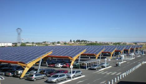


4 Building integration of photovoltaics 7 Building integration of photovoltaics Integration with partial shadowing 8 4


: 1 kwh/m 2 World")

5 PV fields 9 Solar energy potential Yearly solar energy irradiation on Earth x World energy consumption One hour of solar irradiation on Earth surface Yearly World energy consumption Irradiation (sea level, full sun): 1 kwh/m 2 World primary energy consumption : Energy: >11 GToe Power > 13 TW Toe : Ton oil equivalent 10 MWh 10 5
 electrical power for solar cells with 8% efficiency")
6 Potential of PV electricity generation Sunlight hitting the dark discs could power the whole world 18 TW (averaged) electrical power for solar cells with 8% efficiency covering the area of the black dots! 11 Basics of PV 6

7 PV device - Physical principle step process : 1) Absorption of a photon in a semiconductor to create a free electron-hole pair 2) Separation of the electron-hole pair thanks to the internal electric field of a diode and carrier collection 13 Solar spectra Black body at 6000 K AM0 AM1.5 solar radiation reaching the Earth and absorption bands due to the atmosphere. Typical clear sky absorption and scattering of incident sunlight. Source PVCDROM 14 7
8 Air mass Air Mass : Attenuation (through the atmosphere) AM 1 cos where is the angle between the sun beam and the vertical direction. AM0: solar spectrum (outside of the atmosphere) AM1: solar spectrum on earth surface when the sun is at the vertical direction AM1.5: angle of 45 of the sun with respect to the vertical direction. AMx defines both the spectrum and the radiation intensity. AM mw/cm 2 AM1.5G (Global), AM1.5D (Direct) Efficiencies of PV systems are usually calibrated at this intensity. 15 Spectral change of illumination Daily (and seasonal) changes of spectral irradiation density Spectral irradiaton density [W/m 2 nm AM0 (data) AM1 AM1.5 (data) AM2 AM AM0: space AM1: equator AM1.5 (central Europe, equinox, noon, 48 above horizon) 30 above horizon 20 above horizon Wavelength [nm] Differences mostly in the visible part of the spectrum Maximum irradiation (normal surface): 1 kw/m 2 Yearly irradiation (Switzerland): kwh/m 2 /year (dependent on the local climatic conditions) 16 8
9 Forbidden gap Ge Si Cu S InP GaAs 2 2 E c E v E g = E c - E v ( gap ) a-ge:h CdTe AlSb Conduction band Valence band a-si:h Cu O Se GaP CdS Every semiconductor has a fixed gap E g, E g is temperature dependent. 2 categories of semiconductors: Simple elements (Si, Ge, C, Se...). Alloys and compounds semiconductors: III-V type (GaAs, AlSb, InP), II-VI type (CdS, ZnSe) or others (Cu 2 O, CuInSe 2, organics) E g [ev] gap E g of various semiconductor material at T=300 K 17 Electron-hole pair creation E c E = ph hv = E g E v E g Conduction band Valence band Optical absorption Three different situations: 1. E ph = E g E c E = ph hv > E g E v E g Conduction band Valence band 2. E ph > E g - Impact ionization (if E ph» E g or in case of high electric field) is negligible in the case of solar cell E c E = hv < E ph g E v E g = E c- E v Conduction band Gap states due to defects or impurities Valence band 3. E ph < E g No absorption Absorption only in presence of gap states (defects or impurities); 18 9
10 Absorption process High band gap (e.g. a-si) Low band gap (e.g. mc-si) Photons with energy less than the band gap are not absorbed Photon energy in excess of band gap is lost to thermalization 19 Bandgaps Direct bandgap semiconductors: GaAs, InP, High absorption coefficient Indirect bandgap semiconductors: Si, Ge, AlSb, GaP Phonon must be absorbed or emitted Lower probability than direct excitation (without phonon interaction) lower absorption coefficient Non direct bandgap: Disordered semiconductors 20 10
11 Spectral conversion efficiency c-ge (crystalline Germanium), E g = 0.66 ev (small gap) Incident photons Incident photons Ge Si Almost all photon are absorbed 40% s c-si (crystalline Silicon), E g = 1.12 ev (medium gap) Une big part of the photons are Absorbed; IR photons are not. 48% s Cu 2 O (Cupper oxide), E g = 2.1 ev (big gap) Spectral conversion efficiency S (physical limit of the conversion efficiency) S or S E g Energy content of the solar spectrum per unit of time where f is the photon flux f ( g fq)(e / q) Energy content of thesolar spectrum per unit of time Incident photons Cu 2O Une small part of the photons are absorbed Remarks: (f q) corresponds to an electrical current (E g / q) corresponds to an electric potential 28% s 21 Spectral conversion efficiency Spectral conversion efficiency s Ge CIS c-si GaAs / CdTe a-si:h Se E g [ev] spectral conversion efficiency s as a function of gap E g under AM1.5 illumination S depends on light spectrum semiconductor gap Optimum bandgap for each spectrum Combination of semiconductors with different gaps may increase S Incident photons Combination of 2 semiconductors with different gaps: With these 2 materials: s >60%. Cu2O (large Eg) Si (small Eg) 1. High energy photons are absorbed 2. Low energy photons are absorbed 22 11
 Spectral loss (no absorption & thermalisation) Maximum : 33.7% for AM1.5 Wikipedia http://sbyrnes321.byethost11.com/sq.")
12 Shockley-Queisser limit Fundamental efficiency limit of a (single junction) solar cell Considerations Blackbody radiation (radiation loss, depends on solar cell temperature) Recombination (only radiative, recombination of free holes and electrons) Spectral loss (no absorption & thermalisation) Maximum : 33.7% for AM1.5 Wikipedia 23 Device operation 12
13 Electron-hole pair separation p-n diode: carriers collection by diffusion process crystalline solar cells Crystalline Si solar cell p-i-n structure carriers collection by drift amorphous solar cells photodetectors (crystalline or amorphous) a-si:h p-i-n solar cell Ag Ag SiO 2 n+ Glass SnO 2 p-type a-sic:h p++ diffusion - + p-type sc Si µm p++ Al - intrinsic a-si:h µm n-type a-si:h Al or Ag drift + M. Zeman, Delft University 25 Band diagram Crystalline Si solar cell a-si:h p-i-n solar cell n + p p + p i n E C Energy [ev] E V E F Energy [ev] E F E C E V Depth [μm] 0 Depth [nm] 300 M. Zeman, Delft University 26 13
14 What is a solar cell: First approximation In darkness: Solar cell = diode I V I R V qv I I0 exp( ) 1 kt Basic equivalent circuit I-V (current voltage) curve Ideal diode equation Under illumination = A diode + a current source in parallel with current I L I I L I D V qv I I L I D I L I0 exp( ) 1 kt I -I L V Power can be delivered to a load! 27 Solar cell I-V curve Analyses of I-V curve I -V max V oc V I L I D I Short-circuit Conditions I = -I sc, V=0 -I max P max I L I D I V Open-circuit Conditions I=0, V = V oc, -I sc Power P max I L I D I R M Ideal power dissipation on V R M =V max /I max 28 14

15 Equivalent circuit of a p-n solar cell I L I I D p V I R p s R s R R oc I dv di V oc Strictly applicable to p-n junction (c-si). Approximately applicable to thin-film solar cells The series resistance R s characterizes the resistance of the metallic connections the resistance of the metal-semiconductor interfaces (ohmic contacts); the resistance of the semiconducting layers. The parallel resistance (or shunt) R p characterizes: the leakage currents at the junction periphery the impurities in the junctions additional (with respect to the ideal diode) recombination. R R p Isc dv di V 0 R s series resistance (must be small) R p parallel resistance (must be high) I qv IR nkt s I L I0 exp( ) 1 V IRs R p 29 Current generation/dissipation Photovoltaics CD-ROM 30 15
16 Device performance limits Ideal p-n junction and junction formation p-type Free holes Excited acceptor states n-type Free electrons Excited donor states Depletion region = Space charge region Diffusion of holes Depletion region Diffusion of electrons In the depletion region : Diffusion currents = drift currents Ideal diode Total depletion Quasi neutral bulk region and space region with fully ionized donor/acceptor states Sharp interfaces n-region with n»p p-region with p»n Drift process negligible for minority carriers Very thin depletion region 32 16
17 Thermal equilibrium diagram E Drift p-type Diffusion qf i E c E F Diffusion Drift n-type E i E v x p x n x p-bulk region Depletion/spacecharge region n-bulk region In thermal equilibrium: drift current = diffusion current 33 Diode equation (Shockley) Ideal I(V) characteristics in the dark (diffusion model) Solving the transport, continuity and Poisson equations (for an ideal p-n diode): qv I dark I0 exp 1 kbt with where 2 2 qdnn qdpn i i I0 A LnnA LpnD k : the Boltzmann constant q: the elementary charge T: the absolute temperature A: the junction area n A, n D : the dopant densities n i : intrinsic carrier density D p, D n : diffusion constants of the minority carriers in the p, resp, n region L p, L n : diffusion length of the minority carriers in the p, resp, n region 34 17
18 Empirical expression The theoretical expression of the saturation current I 0 comprises parameters that have to be determined experimentally It can be replaced by a more simple empirical expression where the minimum saturation current I 0 is given by: E 8 g I exp 0 k T B ma in cm This empirical expression is an important basis for the calculation of the theoretical maximum of V oc, FF et When generation and recombination in the depletion region is not neglected: 2 I dark qv qv I 0 exp 1 I w exp 1 kbt 2kBT Additional term due to the recombination, which depends on the gap, carrier lifetimes, doping concentrations, applied voltage, etc. 35 Ideality factor We can replace I dark 0 w qv qv I exp 1 I exp 1 kbt 2kBT with I dark 0 qv I exp 1 nkbt where n is the ideality factor which varies between 1 and 2 : n =1 : ideal case n= 2 : recombination current is dominant. a-si p-i-n case: 1.3 < n <
19 Superposition principle "Superposition" principle of the photogenerated current I L I Dark I(V) = I dark (V) - I L I L -V max V oc V Illuminated Principle valid for a p-n diode in ideal conditions (in general not valid for thin film diodes) -I max Maximum power -I sc 37 Short-circuit current I sc Experimental data Assuming R s = 0 et R p = cell thickness sufficient for absorbing all useful light total collection of the carriers no recombination. Ideal illuminated diode in short-circuit condition I sc =I L Theoretical maximum of I sc given by : solar spectrum semiconductor gap: I sc = fq, with f: number of photogenerated "electronhole" pairs per unit time q: elementary charge Theoretical maximum short-circuit current under AM1.5 illumination Effect of the temperature: I sc only very weakly temperature dependent (E g decreases when the temperature increases)
20 Open-circuit voltage V oc The voltage supplied by a cell directly depends on gap E g From the empirical expression of the ideal p-n diode V oc k B T q ln 1 I L 1, ma/cm 2 E g q V oc is a quasi linear function of the gap Open-circuit voltage Voc as a function of the gap for a AM1.5 illumination with the approximations: (1) V oc 2 E g 3 q (2) V oc k BT q ln 1 I L 1, ma/cm 2 E g q where the values I L are obtained from the Fig. 7.26, (3) theoretical limit of Kiess [Kiess, 1995] Experimental data Limits 2 Eg E g /q is an upper bound for V oc : Voc 3 q V oc increases if I L increases advantage of cells working with light concentration (higher efficiencies). Temperature effect V oc decreases almost linearly when the temperature increases (0,4% per degree Celsius for c-si). 39 Fill-factor and cell power I Fill- factor FF defined as -V max V oc V ImV FF I V sc m oc -I max -I sc Maximum power P max =FF I sc V oc where I m, V m are the current and voltage when the cell output power is maximum (maximum power point) 40 20
21 Fill-factor FF FF is only a function of the opencircuit voltage V oc (in the diffusion model of the p-n diode). voc lnvoc 0.72V FF voc 1 V with oc voc nk T / q valid for v oc >10, n: ideality factor B Experimental data semi-empirical value of Fill-factor FF as a function of the gap for two values of the ideality factor n and for an AM1.5 illumination. FF is a very sensitive indication of the solar cell quality! For a quality solar cell: 0.7 < FF < 0.8 (a-si:h) 0.8 < FF < 0.85 (c-si) Temperature effect: FF decreases with an increase of the temperature (due to the change of V oc with temperature). 41 Efficiency The efficiency is defined as: P max P inc with P max = I m V m = FF I sc V oc The total solar cell efficiency is given by: p. / n s Experimental data maximum "theoretical" limit as a function of gap E g under AM1.5 illumination p/n being the efficiency of the carrier separation (second step) Voc p / n FF Eg / q and s the spectral conversion efficiency. Practically = I sc [ma/cm 2 ] V oc [V] FF / 100 [mw/cm 2 ] 42 21

22 Efficiency dependences rel Intensity : 100 mw/cm 2 100% 75% 50% Effect of temperature For c-si : decreases by %/ C For a-si : decreases by %/ C Decrease is less important for high bandgap materials. 25% T = 25 C 14% Si-Mono 12% Si-Poly 6% 0 0,5 1 1,5 T[ C] Sun 2 Effect of the light intensity decreases with a decrease of the light intensity (I L /I 0 ration of V oc, and loss in R p ). decreases at high values of the intensity (loss in R s, increase of the temperature, diffusion model no more valid for diode model under high injection). 43 Quantum efficiency or front dead layer or insufficiently thick diodes - + PVCDROM 44 22
23 Multi-junction devices Monolithic tandem n + 2,50 Map of max. efficiency (AM1.5) 0 2,25 0, , ,00 0,1298 p + n + E g bottom [ev] 1,75 1,50 1,25 0,1730 0,2163 0,2595 0,3028 0,3460 1,00 0,75 0,50 0,50 0,75 1,00 1,25 1,50 1,75 2,00 2,25 2,50 E g top [ev] Two terminal device Current matching required, narrower region of high efficiency compared to four terminal devices 46 23
24 Tandem equivalent circuit top cell bottom cell RL Top cell: I top = I top (V top ) Bottom cell: I bot = I bot (V bot ) Tandem cell: I = I top = I bot V(I) = V top (I) + V bot (I) I min (I sc,top, I sc,bot ) V oc = V oc,top + V oc,bot 16 Simple cell (single junction) 12 I [ma/cm 2 ] 8 Tandem cell V [V] typical I(V) curves of a single-junction and tandem a-si:h cells 47 PV technologies 24

25 PV technologies Bulk technologies: Monocrystalline silicon Polycrystalline silicon Ribbon silicon GaAs (space application, concentrators), InP (space application) Thin-film technologies: Amorphous silicon Micro-/nano-crystalline silicon. micromorph CdTe (Cadmium telluride) CIGS (Cupper Indium Gallium Diselenide) CIS (Cupper Indium Diselenide, Cupper Indium Sulfide) Others: Dye cells, Graetzel Organic cells, polymers 49 Conversion efficiency vs. time Commercial cells exhibit efficiencies reduced by 20-60% 50 25


26 PV Development Installed capacity (2013) PV installed: > 134 GW, 2013 : GW (fastest growth in Asia) World share of PV in electricity production : 0.85% EIA PVPS Report 51 c-si standard technology Screen printed solar cells Buried Contact Solar Cells PVCDROM 52 26
 cell 25.")
 as super-passivation layers, as well as a-si p+ emitter layer (~")
: 25.")
27 High efficiency c-si cells Sunpower back contact solar cells 24.2% efficiency UNSW PERL (passivated emitter with rear locally diffused) cell 25.0% efficiency 53 HIT cell Band diagram of the HIT cell: (a) ideal double heterojunction; (b) estimated HIT structure: a-si intrinsic layers (~ 5 nm) as super-passivation layers, as well as a-si p+ emitter layer (~ 10 nm) on the front and a-si n+ contact layer (~ 15 nm) on the rear. ITO transparent contact Best lab efficiency (Panasonic/Sanyo): 25.6% (100 cm 2 ), V oc > 700 mv Highest efficiency for c-si cells Thermal coefficient: %/ C for V oc, %/ C for (lower than that of c-si!) 54 27
28 Si thin-film technologies Thin-film silicon characteristics a-si:h Medium gap (1.75 ev) Short-range order High hydrogen content, alloy with H (10-20%) Low defect density (H passivation) Very high resistivity, semiisolating (>10 10 cm) Deposited mainly by PE-CVD Various substrates possible Large area deposition µc-si:h (for PV applications) Low gap material (1.1 ev) few nm grain size (nano-crystalline silicon) Short-medium range order Medium hydrogen content (few %) Low defect density (H passivation) Presence of a-si:h incubation layer, a-si:h inter-grain tissue High resistivity ( cm) Deposited mainly by PE-CVD Various substrates possible Large area deposition 56 28
29 a-si:h optical absorption Absorption coefficient [1/cm] Wavelength [micrometers] Subbandgap defects a-sige:h a-si:h p-type a-sic:h c Si Photon energy [ev] Absorption coefficient «non-direct semiconductor» In visible part of spectrum 70 x higher than c-si Thin film (about 1 micron) absorbs 90% of usable solar energy Optical band gap Tunable Depends on H content a-si:h based materials alloys C increases E g Ge decreases E g 57 p-i-n solar cell 100 Å µm 200 Å Anti-reflection coating Glass superstrate Transparent Conductive Oxide p-type Intrinsic a-si:h n-type Back contact - + p-i-n structure necessary for disordered semiconductors Doped layer are very defective (dead layers) Doped layers only serve for electric field build-up through the intrinsic layer The intrinsic layer is the only active layer. Light enters the cell through the p-layer ( window layer ) Minimization of hole collection path (low hole mobility) Higher bandgap for p-layer (low optical loss) Electrically thin diode High electrical field minimal recombination in i-layer Optically thick diode maximum absorption of light Minimal thickness (processing time) Light trapping scheme 58 29
 deposited by LP-CVD Roughness depends on film thickness and temperature 59 Multi-junction device for higher efficiency Tandems a-si:h / a-sige:h a-si:h /")
 Current matching, very thin top a-sige:h stability mc-ge:h")
30 Light trapping for thin film silicon cells Glass Front ZnO p-i-n ZnO Back reflector Rough transparent conductive oxides (TCO) Back reflector Tin Oxide (SnO 2 ) deposited by AP-CVD Roughness depends on deposition process Zinc Oxide (ZnO) deposited by LP-CVD Roughness depends on film thickness and temperature 59 Multi-junction device for higher efficiency Tandems a-si:h / a-sige:h a-si:h / mc-si:h (mircomorph) a-si:h / a-si:h Triples a-sic:h / a-si:h / a-sige:h a-si:h / a-sige:h / a-sige:h a-si:h / mc-si:h / mc-si:h a-si:h / a-si:h / mc-si:h a-si:h / a-sige:h / mc-si:h a-si:h / mc-si:h / mc-ge:h Issues a-sige:h stability mc-si:h processing a-sic:h & a-sige:h stability a-sige:h stability Current matching (thick bottom) Current matching, very thin top a-sige:h stability mc-ge:h processing (commercially available devices in red) 60 30
31 Examples Back contact µc-si:h Bottom cell (1.1 ev gap) a-si:h Top cell (1.75 ev gap) TCO Glass Micromorph Tandem devices comprising Introduced by IMT (EPFL) Advantages: Better usage of solar spectrum Higher efficiency and stability Intensity [kw/m 2 /µm] µc-si:h a-si:h Wavelength [nm] Light UniSolar monolithic triple junction, flexible modules on steel: -stable cell efficiency: 13.1% -module efficiency ~8% ~1.8 ev ~1.6 ev ~1.4 ev 61 PV modules 31

 Monolithic interconnection for thin-film cells 63")

32 Module serial connection Bulk technologies V 0.6 V 0.6 V 0.6 V Thin-film technologies + - Metall p-i-n TCO Substrate (glass, polymer or isolated metal) Monolithic interconnection for thin-film cells 63 Monolithic interconnection Deposition of TCO on glass Deposition of back contact Laser scribing of TCO Laser scribing of back contact Deposition of a-si diode Testing of finished module Laser scribing of a-si:h diode Active area Dead area 64 32


![voltage [V]](/docs-images/72/68007911/images/33-6.jpg "200 800")


33 PV with thin film Si 65 Microrobots Solar modules for micro-systems High voltage modules Up to 180 V from 3x3 mm 2 Output voltage [V] mv/segment First module generation Second module generation Number of segments 66 33
34 a-si photodiodes Thin-film Solar cells vs Photodiodes hn p i n A Using primary photoconductivity (device with blocking contacts) given by the collection of photo-generated carriers I ph =Ge with : quantum efficiency, 1 (a-si:h cells) blocking contact: diode characteristic Operation conditions for a photodiode Current density dark illuminated I ph Operation conditions for a solar cell Voltage 68 34


 Above IC technology Elevated diode Benefits High fill-factor, high sensitivity No trade off between")
35 Fluorescence detector, microfluidic A Schematic crosssectional view of a microlens and an integrated a-si:h fluorescence detector, forming a compact platform where microfluidic CE device is mounted. B Optical micrograph of the top view of the integrated fluorescence detector. Kamei, MRS Vertical Integration of Detector Arrays Front electrode a-si:h photodiode layer Back electrode Insulation layer CMOS circuit Technology known as Thin-Film on ASIC (TFA) Thin-Film on CMOS (TFC) Above IC technology Elevated diode Benefits High fill-factor, high sensitivity No trade off between sensitivity and circuit complexity No dead area 70 35

: 56")

36 TFA imagers Visible light X-ray detection Metal-i-p a-si:h diodes deposited on unpassivated chip 64x64 pixels 38.4 µm size, 40 µm pitch 92% fill factor Pixels connect to charge integrators Dark current as low as 20 pa/cm2 Noise (fixed patterned noise Sensitivity 56 V/(µJcm2) Dynamic Range: >60 db 4x4 mm 2 ASIC 48 pixels with 150 µm size and 380 µm pitch connected to active feedback amplifiers 15 µm thick a-si:h diode N. 71 PV ressources
37 Bibliography Books S.M. Sze, Semiconductor Devices Solar Cells: Operating Principles, Technology and System Applications, M. Green, University of New South Wales Silicon Solar Cells: Advanced Principles and Practice, M.A. Green, University of New South Wales A. Shah, Thin-film silicon solar cells, EPFL Press, J. Kanicki, Amorphous and Microcrystalline Semiconductor Devices, 1991, Artech House R.A. Street, Hydrogenated Amorphous Silicon, Cambridge University Press, A. Ricaud, Photopiles solaires, PPUR, 1997 A. Goetzberger, Sonnenergie: Photovoltaik, Teubner, Other Photovoltaics: Devices, Systems and Applications CD-ROM by C. Honsberg and S. Bowden, University of New South Wales, 2 nd edition online at :
Chapter 7. Solar Cell
 Chapter 7 Solar Cell 7.0 Introduction Solar cells are useful for both space and terrestrial application. Solar cells furnish the long duration power supply for satellites. It converts sunlight directly
Photovoltaic cell and module physics and technology
 Photovoltaic cell and module physics and technology Vitezslav Benda, Prof Czech Technical University in Prague benda@fel.cvut.cz www.fel.cvut.cz 6/21/2012 1 Outlines Photovoltaic Effect Photovoltaic cell
PHOTOVOLTAICS Fundamentals
 PHOTOVOLTAICS Fundamentals PV FUNDAMENTALS Semiconductor basics pn junction Solar cell operation Design of silicon solar cell SEMICONDUCTOR BASICS Allowed energy bands Valence and conduction band Fermi
Photovoltaic cell and module physics and technology. Vitezslav Benda, Prof Czech Technical University in Prague
 Photovoltaic cell and module physics and technology Vitezslav Benda, Prof Czech Technical University in Prague benda@fel.cvut.cz www.fel.cvut.cz 1 Outlines Photovoltaic Effect Photovoltaic cell structure
Solar cells operation
 Solar cells operation photovoltaic effect light and dark V characteristics effect of intensity effect of temperature efficiency efficency losses reflection recombination carrier collection and quantum
February 1, 2011 The University of Toledo, Department of Physics and Astronomy SSARE, PVIC
 FUNDAMENTAL PROPERTIES OF SOLAR CELLS February 1, 2011 The University of Toledo, Department of Physics and Astronomy SSARE, PVIC Principles and Varieties of Solar Energy (PHYS 4400) and Fundamentals of
Electrons are shared in covalent bonds between atoms of Si. A bound electron has the lowest energy state.
 Photovoltaics Basic Steps the generation of light-generated carriers; the collection of the light-generated carriers to generate a current; the generation of a large voltage across the solar cell; and
EE 5611 Introduction to Microelectronic Technologies Fall Tuesday, September 23, 2014 Lecture 07
 EE 5611 Introduction to Microelectronic Technologies Fall 2014 Tuesday, September 23, 2014 Lecture 07 1 Introduction to Solar Cells Topics to be covered: Solar cells and sun light Review on semiconductor
Photovoltaic Energy Conversion. Frank Zimmermann
 Photovoltaic Energy Conversion Frank Zimmermann Solar Electricity Generation Consumes no fuel No pollution No greenhouse gases No moving parts, little or no maintenance Sunlight is plentiful & inexhaustible
smal band gap Saturday, April 9, 2011
 small band gap upper (conduction) band empty small gap valence band filled 2s 2p 2s 2p hybrid (s+p)band 2p no gap 2s (depend on the crystallographic orientation) extrinsic semiconductor semi-metal electron
OPTI510R: Photonics. Khanh Kieu College of Optical Sciences, University of Arizona Meinel building R.626
 OPTI510R: Photonics Khanh Kieu College of Optical Sciences, University of Arizona kkieu@optics.arizona.edu Meinel building R.626 Announcements Homework #6 is assigned, due May 1 st Final exam May 8, 10:30-12:30pm
3.1 Introduction to Semiconductors. Y. Baghzouz ECE Department UNLV
 3.1 Introduction to Semiconductors Y. Baghzouz ECE Department UNLV Introduction In this lecture, we will cover the basic aspects of semiconductor materials, and the physical mechanisms which are at the
High efficiency silicon and perovskite-silicon solar cells for electricity generation
 High efficiency silicon and perovskite-silicon solar cells for electricity generation Ali Dabirian Email: dabirian@ipm.ir 1 From Solar Energy to Electricity 2 Global accumulative PV installed In Iran it
The Opto-Electronic Physics That Just Broke the Efficiency Record in Solar Cells
 The Opto-Electronic Physics That Just Broke the Efficiency Record in Solar Cells Solar Energy Mini-Series Jen-Hsun Huang Engineering Center Stanford, California Sept. 26, 2011 Owen D. Miller & Eli Yablonovitch
Solar Photovoltaics & Energy Systems
 Solar Photovoltaics & Energy Systems Lecture 4. Crystalline Semiconductor Based Solar Cells ChE-600 Wolfgang Tress, May 2016 1 Photovoltaic Solar Energy Conversion 2 Semiconductor vs. Heat Engine spectral
EE 446/646 Photovoltaic Devices I. Y. Baghzouz
 EE 446/646 Photovoltaic Devices I Y. Baghzouz What is Photovoltaics? First used in about 1890, the word has two parts: photo, derived from the Greek word for light, volt, relating to electricity pioneer
Lab #5 Current/Voltage Curves, Efficiency Measurements and Quantum Efficiency
 Lab #5 Current/Voltage Curves, Efficiency Measurements and Quantum Efficiency R.J. Ellingson and M.J. Heben November 4, 2014 PHYS 4580, 6280, and 7280 Simple solar cell structure The Diode Equation Ideal
Chapter 1 Overview of Semiconductor Materials and Physics
 Chapter 1 Overview of Semiconductor Materials and Physics Professor Paul K. Chu Conductivity / Resistivity of Insulators, Semiconductors, and Conductors Semiconductor Elements Period II III IV V VI 2 B
Classification of Solids
 Classification of Solids Classification by conductivity, which is related to the band structure: (Filled bands are shown dark; D(E) = Density of states) Class Electron Density Density of States D(E) Examples
ET3034TUx Utilization of band gap energy
 ET3034TUx - 3.3.1 - Utilization of band gap energy In the last two weeks we have discussed the working principle of a solar cell and the external parameters that define the performance of a solar cell.
Lecture 2. Introduction to semiconductors Structures and characteristics in semiconductors
 Lecture 2 Introduction to semiconductors Structures and characteristics in semiconductors Semiconductor p-n junction Metal Oxide Silicon structure Semiconductor contact Literature Glen F. Knoll, Radiation
FYS 3028/8028 Solar Energy and Energy Storage. Calculator with empty memory Language dictionaries
 Faculty of Science and Technology Exam in: FYS 3028/8028 Solar Energy and Energy Storage Date: 11.05.2016 Time: 9-13 Place: Åsgårdvegen 9 Approved aids: Type of sheets (sqares/lines): Number of pages incl.
Introduction. Katarzyna Skorupska. Silicon will be used as the model material however presented knowledge applies to other semiconducting materials
 Introduction Katarzyna Skorupska Silicon will be used as the model material however presented knowledge applies to other semiconducting materials 2 June 26 Intrinsic and Doped Semiconductors 3 July 3 Optical
Solar Photovoltaics & Energy Systems
 Solar Photovoltaics & Energy Systems Lecture 3. Crystalline Semiconductor Based Solar Cells ChE-600 Wolfgang Tress, March 2018 1 Photovoltaic Solar Energy Conversion 2 Outline Recap: Thermodynamics of
1 Name: Student number: DEPARTMENT OF PHYSICS AND PHYSICAL OCEANOGRAPHY MEMORIAL UNIVERSITY OF NEWFOUNDLAND. Fall :00-11:00
 1 Name: DEPARTMENT OF PHYSICS AND PHYSICAL OCEANOGRAPHY MEMORIAL UNIVERSITY OF NEWFOUNDLAND Final Exam Physics 3000 December 11, 2012 Fall 2012 9:00-11:00 INSTRUCTIONS: 1. Answer all seven (7) questions.
Lecture 15: Optoelectronic devices: Introduction
 Lecture 15: Optoelectronic devices: Introduction Contents 1 Optical absorption 1 1.1 Absorption coefficient....................... 2 2 Optical recombination 5 3 Recombination and carrier lifetime 6 3.1
LEC E T C U T R U E R E 17 -Photodetectors
 LECTURE 17 -Photodetectors Topics to be covered Photodetectors PIN photodiode Avalanche Photodiode Photodetectors Principle of the p-n junction Photodiode A generic photodiode. Photodetectors Principle
Comparison of Ge, InGaAs p-n junction solar cell
 ournal of Physics: Conference Series PAPER OPEN ACCESS Comparison of Ge, InGaAs p-n junction solar cell To cite this article: M. Korun and T. S. Navruz 16. Phys.: Conf. Ser. 77 135 View the article online
Lecture 2. Introduction to semiconductors Structures and characteristics in semiconductors
 Lecture 2 Introduction to semiconductors Structures and characteristics in semiconductors Semiconductor p-n junction Metal Oxide Silicon structure Semiconductor contact Literature Glen F. Knoll, Radiation
Thermionic Current Modeling and Equivalent Circuit of a III-V MQW P-I-N Photovoltaic Heterostructure
 Thermionic Current Modeling and Equivalent Circuit of a III-V MQW P-I-N Photovoltaic Heterostructure ARGYRIOS C. VARONIDES Physics and Electrical Engineering Department University of Scranton 800 Linden
EE495/695 Introduction to Semiconductors I. Y. Baghzouz ECE Department UNLV
 EE495/695 Introduction to Semiconductors I Y. Baghzouz ECE Department UNLV Introduction Solar cells have always been aligned closely with other electronic devices. We will cover the basic aspects of semiconductor
Chemistry Instrumental Analysis Lecture 8. Chem 4631
 Chemistry 4631 Instrumental Analysis Lecture 8 UV to IR Components of Optical Basic components of spectroscopic instruments: stable source of radiant energy transparent container to hold sample device
Lecture 2. Photon in, Electron out: Basic Principle of PV
 Lecture 2 Photon in, Electron out: Basic Principle of PV References: 1. Physics of Solar Cells. Jenny Nelson. Imperial College Press, 2003. 2. Third Generation Photovoltaics: Advanced Solar Energy Conversion.
Toward a 1D Device Model Part 1: Device Fundamentals
 Toward a 1D Device Model Part 1: Device Fundamentals Lecture 7 9/29/2011 MIT Fundamentals of Photovoltaics 2.626/2.627 Fall 2011 Prof. Tonio Buonassisi 1 Learning Objectives: Toward a 1D Device Model 1.
ELECTRONIC DEVICES AND CIRCUITS SUMMARY
 ELECTRONIC DEVICES AND CIRCUITS SUMMARY Classification of Materials: Insulator: An insulator is a material that offers a very low level (or negligible) of conductivity when voltage is applied. Eg: Paper,
Single Photon detectors
 Single Photon detectors Outline Motivation for single photon detection Semiconductor; general knowledge and important background Photon detectors: internal and external photoeffect Properties of semiconductor
Chapter 1. Solar energy conversion: from amorphous silicon to Dye-Sensitized Solar Cells. 1.1 Photovoltaic history.
 Chapter 1 Solar energy conversion: from amorphous silicon to Dye-Sensitized Solar Cells 1.1 Photovoltaic history. 1.2 Operation of traditional photovoltaic devices. 1.3 Thin film solar cells. 1.4 Multijunction
Introduction to Photovoltaics
 INTRODUCTION Objectives Understand the photovoltaic effect. Understand the properties of light. Describe frequency and wavelength. Understand the factors that determine available light energy. Use software
Lecture 2. Introduction to semiconductors Structures and characteristics in semiconductors. Fabrication of semiconductor sensor
 Lecture 2 Introduction to semiconductors Structures and characteristics in semiconductors Semiconductor p-n junction Metal Oxide Silicon structure Semiconductor contact Fabrication of semiconductor sensor
Electron Energy, E E = 0. Free electron. 3s Band 2p Band Overlapping energy bands. 3p 3s 2p 2s. 2s Band. Electrons. 1s ATOM SOLID.
 Electron Energy, E Free electron Vacuum level 3p 3s 2p 2s 2s Band 3s Band 2p Band Overlapping energy bands Electrons E = 0 1s ATOM 1s SOLID In a metal the various energy bands overlap to give a single
Physics of the thermal behavior of photovoltaic cells
 Physics of the thermal behavior of photovoltaic cells O. Dupré *,2, Ph.D. candidate R. Vaillon, M. Green 2, advisors Université de Lyon, CNRS, INSA-Lyon, UCBL, CETHIL, UMR58, F-6962 Villeurbanne, France
EE 5344 Introduction to MEMS CHAPTER 5 Radiation Sensors
 EE 5344 Introduction to MEMS CHAPTER 5 Radiation Sensors 5. Radiation Microsensors Radiation µ-sensors convert incident radiant signals into standard electrical out put signals. Radiant Signals Classification
Conductivity and Semi-Conductors
 Conductivity and Semi-Conductors J = current density = I/A E = Electric field intensity = V/l where l is the distance between two points Metals: Semiconductors: Many Polymers and Glasses 1 Electrical Conduction
Goal for next generation solar cells: Efficiencies greater than Si with low cost (low temperature) processing
 processing") Multi-junction cells MBE growth > 40% efficient Expensive Single crystal Si >20% efficient expensive Thin film cells >10% efficient Less expensive Toxic materials Polymers
Multi-junction cells MBE growth > 40% efficient Expensive Single crystal Si >20% efficient expensive Thin film cells >10% efficient Less expensive Toxic materials Polymers
Chapter 4. Photodetectors
 Chapter 4 Photodetectors Types of photodetectors: Photoconductos Photovoltaic Photodiodes Avalanche photodiodes (APDs) Resonant-cavity photodiodes MSM detectors In telecom we mainly use PINs and APDs.
Third generation solar cells - How to use all the pretty colours?
 Third generation solar cells - How to use all the pretty colours? Erik Stensrud Marstein Department for Solar Energy Overview The trouble with conventional solar cells Third generation solar cell concepts
Carrier Recombination
 Notes for ECE-606: Spring 013 Carrier Recombination Professor Mark Lundstrom Electrical and Computer Engineering Purdue University, West Lafayette, IN USA lundstro@purdue.edu /19/13 1 carrier recombination-generation
Fundamentals of Photovoltaics: C1 Problems. R.Treharne, K. Durose, J. Major, T. Veal, V.
 Fundamentals of Photovoltaics: C1 Problems R.Treharne, K. Durose, J. Major, T. Veal, V. Dhanak @cdtpv November 3, 2015 These problems will be highly relevant to the exam that you will sit very shortly.
Course overview. Me: Dr Luke Wilson. The course: Physics and applications of semiconductors. Office: E17 open door policy
 Course overview Me: Dr Luke Wilson Office: E17 open door policy email: luke.wilson@sheffield.ac.uk The course: Physics and applications of semiconductors 10 lectures aim is to allow time for at least one
KATIHAL FİZİĞİ MNT-510
 KATIHAL FİZİĞİ MNT-510 YARIİLETKENLER Kaynaklar: Katıhal Fiziği, Prof. Dr. Mustafa Dikici, Seçkin Yayıncılık Katıhal Fiziği, Şakir Aydoğan, Nobel Yayıncılık, Physics for Computer Science Students: With
Lecture 12. Semiconductor Detectors - Photodetectors
 Lecture 12 Semiconductor Detectors - Photodetectors Principle of the pn junction photodiode Absorption coefficient and photodiode materials Properties of semiconductor detectors The pin photodiodes Avalanche
Basic Limitations to Third generation PV performance
 Basic Limitations to Third generation PV performance Pabitra K. Nayak Weizmann Institute of Science, Rehovot, Israel THANKS to my COLLEAGUES Lee Barnea and David Cahen. Weizmann Institute of Science Juan
The Role of doping in the window layer on Performance of a InP Solar Cells USING AMPS-1D
 IOSR Journal of Engineering (IOSRJEN) ISSN: 2250-3021 Volume 2, Issue 8(August 2012), PP 42-46 The Role of doping in the window layer on Performance of a InP Solar Cells USING AMPS-1D Dennai Benmoussa
A. K. Das Department of Physics, P. K. College, Contai; Contai , India.
 IOSR Journal of Applied Physics (IOSR-JAP) e-issn: 2278-4861.Volume 7, Issue 2 Ver. II (Mar. - Apr. 2015), PP 08-15 www.iosrjournals.org Efficiency Improvement of p-i-n Structure over p-n Structure and
MODELING THE FUNDAMENTAL LIMIT ON CONVERSION EFFICIENCY OF QD SOLAR CELLS
 MODELING THE FUNDAMENTAL LIMIT ON CONVERSION EFFICIENCY OF QD SOLAR CELLS Ա.Մ.Կեչիյանց Ara Kechiantz Institute of Radiophysics and Electronics (IRPhE), National Academy of Sciences (Yerevan, Armenia) Marseille
Photodiodes and other semiconductor devices
 Photodiodes and other semiconductor devices Chem 243 Winter 2017 What is a semiconductor? no e - Empty e levels Conduction Band a few e - Empty e levels Filled e levels Filled e levels lots of e - Empty
Electronics The basics of semiconductor physics
 Electronics The basics of semiconductor physics Prof. Márta Rencz, Gergely Nagy BME DED September 16, 2013 The basic properties of semiconductors Semiconductors conductance is between that of conductors
Semiconductor Physical Electronics
 Semiconductor Physical Electronics Sheng S. Li Department of Electrical Engineering University of Florida Gainesville, Florida Plenum Press New York and London Contents CHAPTER 1. Classification of Solids
Basic cell design. Si cell
 Basic cell design Si cell 1 Concepts needed to describe photovoltaic device 1. energy bands in semiconductors: from bonds to bands 2. free carriers: holes and electrons, doping 3. electron and hole current:
Mesoporous titanium dioxide electrolyte bulk heterojunction
 Mesoporous titanium dioxide electrolyte bulk heterojunction The term "bulk heterojunction" is used to describe a heterojunction composed of two different materials acting as electron- and a hole- transporters,
Semiconductor X-Ray Detectors. Tobias Eggert Ketek GmbH
 Semiconductor X-Ray Detectors Tobias Eggert Ketek GmbH Semiconductor X-Ray Detectors Part A Principles of Semiconductor Detectors 1. Basic Principles 2. Typical Applications 3. Planar Technology 4. Read-out
Advantages / Disadvantages of semiconductor detectors
 Advantages / Disadvantages of semiconductor detectors Semiconductor detectors have a high density (compared to gas detector) large energy loss in a short distance diffusion effect is smaller than in gas
Device 3D. 3D Device Simulator. Nano Scale Devices. Fin FET
 Device 3D 3D Device Simulator Device 3D is a physics based 3D device simulator for any device type and includes material properties for the commonly used semiconductor materials in use today. The physical
Sheng S. Li. Semiconductor Physical Electronics. Second Edition. With 230 Figures. 4) Springer
 Springer") Sheng S. Li Semiconductor Physical Electronics Second Edition With 230 Figures 4) Springer Contents Preface 1. Classification of Solids and Crystal Structure 1 1.1 Introduction 1 1.2 The Bravais Lattice
Sheng S. Li Semiconductor Physical Electronics Second Edition With 230 Figures 4) Springer Contents Preface 1. Classification of Solids and Crystal Structure 1 1.1 Introduction 1 1.2 The Bravais Lattice
Semiconductor Devices and Circuits Fall Midterm Exam. Instructor: Dr. Dietmar Knipp, Professor of Electrical Engineering. Name: Mat. -Nr.
 Semiconductor Devices and Circuits Fall 2003 Midterm Exam Instructor: Dr. Dietmar Knipp, Professor of Electrical Engineering Name: Mat. -Nr.: Guidelines: Duration of the Midterm: 1 hour The exam is a closed
The photovoltaic effect occurs in semiconductors where there are distinct valence and
 How a Photovoltaic Cell Works The photovoltaic effect occurs in semiconductors where there are distinct valence and conduction bands. (There are energies at which electrons can not exist within the solid)
ET3034TUx External parameters of an ideal solar cell. How can we determine the performance of a solar cell?
 ET3034TUx - 3.2.1 - External parameters of an ideal solar cell How can we determine the performance of a solar cell? In the previous block we have introduced the J- V curve of an ideal solar cell and its
Semiconductor Junctions
 8 Semiconductor Junctions Almost all solar cells contain junctions between different materials of different doping. Since these junctions are crucial to the operation of the solar cell, we will discuss
Semiconductor Detectors
 Semiconductor Detectors Summary of Last Lecture Band structure in Solids: Conduction band Conduction band thermal conductivity: E g > 5 ev Valence band Insulator Charge carrier in conductor: e - Charge
Designing Information Devices and Systems II A. Sahai, J. Roychowdhury, K. Pister Discussion 1A
 EECS 16B Spring 2019 Designing Information Devices and Systems II A. Sahai, J. Roychowdhury, K. Pister Discussion 1A 1 Semiconductor Physics Generally, semiconductors are crystalline solids bonded into
Engineering 2000 Chapter 8 Semiconductors. ENG2000: R.I. Hornsey Semi: 1
 Engineering 2000 Chapter 8 Semiconductors ENG2000: R.I. Hornsey Semi: 1 Overview We need to know the electrical properties of Si To do this, we must also draw on some of the physical properties and we
Semiconductor-Detectors
 Semiconductor-Detectors 1 Motivation ~ 195: Discovery that pn-- junctions can be used to detect particles. Semiconductor detectors used for energy measurements ( Germanium) Since ~ 3 years: Semiconductor
Unit IV Semiconductors Engineering Physics
 Introduction A semiconductor is a material that has a resistivity lies between that of a conductor and an insulator. The conductivity of a semiconductor material can be varied under an external electrical
Lecture 1. OUTLINE Basic Semiconductor Physics. Reading: Chapter 2.1. Semiconductors Intrinsic (undoped) silicon Doping Carrier concentrations
 silicon Doping Carrier concentrations") Lecture 1 OUTLINE Basic Semiconductor Physics Semiconductors Intrinsic (undoped) silicon Doping Carrier concentrations Reading: Chapter 2.1 EE105 Fall 2007 Lecture 1, Slide 1 What is a Semiconductor? Low
Lecture 1 OUTLINE Basic Semiconductor Physics Semiconductors Intrinsic (undoped) silicon Doping Carrier concentrations Reading: Chapter 2.1 EE105 Fall 2007 Lecture 1, Slide 1 What is a Semiconductor? Low
Analyze the effect of window layer (AlAs) for increasing the efficiency of GaAs based solar cell
 for increasing the efficiency of GaAs based solar cell") American Journal of Engineering Research (AJER) e-issn: 2320-0847 p-issn : 2320-0936 Volume-4, Issue-7, pp-304-315 www.ajer.org Research Paper Open Access Analyze the effect of window layer (AlAs) for
American Journal of Engineering Research (AJER) e-issn: 2320-0847 p-issn : 2320-0936 Volume-4, Issue-7, pp-304-315 www.ajer.org Research Paper Open Access Analyze the effect of window layer (AlAs) for
12/10/09. Chapter 18: Electrical Properties. View of an Integrated Circuit. Electrical Conduction ISSUES TO ADDRESS...
 Chapter 18: Electrical Properties ISSUES TO ADDRESS... How are electrical conductance and resistance characterized? What are the physical phenomena that distinguish? For metals, how is affected by and
B THE SOLAR ARRAY. Theory
 10. THE SOLAR ARRAY You will study a number of the electrical properties of the silicon solar array, its power output and optimum load resistance for maximum power. The silicon solar array is being used
The Opto-Electronic Physics Which Just Broke the Efficiency Record in Solar Cells. Green Photonics Symposium at Technion Haifa, Israel, April 23, 2014
 The Opto-Electronic Physics Which Just Broke the Efficiency Record in Solar Cells Green Photonics Symposium at Technion Haifa, Israel, April 23, 2014 Eli Yablonovitch UC Berkeley Electrical Engineering
Lecture 5 Junction characterisation
 Lecture 5 Junction characterisation Jon Major October 2018 The PV research cycle Make cells Measure cells Despair Repeat 40 1.1% 4.9% Data Current density (ma/cm 2 ) 20 0-20 -1.0-0.5 0.0 0.5 1.0 Voltage
FIBER OPTICS. Prof. R.K. Shevgaonkar. Department of Electrical Engineering. Indian Institute of Technology, Bombay. Lecture: 12.
 FIBER OPTICS Prof. R.K. Shevgaonkar Department of Electrical Engineering Indian Institute of Technology, Bombay Lecture: 12 Optical Sources Fiber Optics, Prof. R.K. Shevgaonkar, Dept. of Electrical Engineering,
PRESENTED BY: PROF. S. Y. MENSAH F.A.A.S; F.G.A.A.S UNIVERSITY OF CAPE COAST, GHANA.
 SOLAR CELL AND ITS APPLICATION PRESENTED BY: PROF. S. Y. MENSAH F.A.A.S; F.G.A.A.S UNIVERSITY OF CAPE COAST, GHANA. OUTLINE OF THE PRESENTATION Objective of the work. A brief introduction to Solar Cell
Lecture 2. Semiconductor Physics. Sunday 4/10/2015 Semiconductor Physics 1-1
 Lecture 2 Semiconductor Physics Sunday 4/10/2015 Semiconductor Physics 1-1 Outline Intrinsic bond model: electrons and holes Charge carrier generation and recombination Intrinsic semiconductor Doping:
Vikram L. Dalal Iowa State University Dept. of Elec. And Comp. Engr Iowa State University. All rights reserved.
 Growth Chemistry and Its Relationship to Amorphous Si Devices for Photovoltaic Energy Conversion Vikram L. Dalal Iowa State University Dept. of Elec. And Comp. Engr. 2002 Iowa State University. All rights
Stanford University MatSci 152: Principles of Electronic Materials and Devices Spring Quarter, Final Exam, June 8, 2010
 Stanford University MatSci 152: Principles of Electronic Materials and Devices Spring Quarter, 2009-2010 Final Exam, June 8, 2010 This is a closed book, closed notes exam. You are allowed two double-sided
AMPS - 1D. A. K. Das Department of Physics, P. K. College, Contai; Contai , India.
 IOSR Journal of Applied Physics (IOSRJAP) eissn: 22784861.Volume 7, Issue 1 Ver. II (Jan.Feb. 2015), PP 2330 www.iosrjournals.org Numerical Simulation of Si 1 x Ge x Thin Film Solar Cell Using AMPS 1D
8.1 Drift diffusion model
 8.1 Drift diffusion model Advanced theory 1 Basic Semiconductor Equations The fundamentals of semiconductor physic are well described by tools of quantum mechanic. This point of view gives us a model of
Photonic Devices Human eye: about 400 nm to 700 nm
 Photonic Devices Human eye: about 400 nm to 700 nm λ [ nm] = 1240 E[ ev ] S. M. Sze, Physics of Semiconductor Devices Sensitivity of the human eye Two LEDs: red (λ = 660 nm) green (λ = 560 nm) emitting
Solar Cell Physics: recombination and generation
 NCN Summer School: July 2011 Solar Cell Physics: recombination and generation Prof. Mark Lundstrom lundstro@purdue.edu Electrical and Computer Engineering Purdue University West Lafayette, Indiana USA
FYS3410 Condensed matter physics
 FYS3410 Condensed matter physics Lecture 23 and 24: pn-junctions and electrooptics Randi Haakenaasen UniK/UiO Forsvarets forskningsinstitutt 11.05.2016 and 18.05.2016 Outline Why pn-junctions are important
EE 6313 Homework Assignments
 EE 6313 Homework Assignments 1. Homework I: Chapter 1: 1.2, 1.5, 1.7, 1.10, 1.12 [Lattice constant only] (Due Sept. 1, 2009). 2. Homework II: Chapter 1, 2: 1.17, 2.1 (a, c) (k = π/a at zone edge), 2.3
A semiconductor is an almost insulating material, in which by contamination (doping) positive or negative charge carriers can be introduced.
 positive or negative charge carriers can be introduced.") Semiconductor A semiconductor is an almost insulating material, in which by contamination (doping) positive or negative charge carriers can be introduced. Page 2 Semiconductor materials Page 3 Energy levels
Semiconductor A semiconductor is an almost insulating material, in which by contamination (doping) positive or negative charge carriers can be introduced. Page 2 Semiconductor materials Page 3 Energy levels
(Co-PIs-Mark Brongersma, Yi Cui, Shanhui Fan) Stanford University. GCEP Research Symposium 2013 Stanford, CA October 9, 2013
 Stanford University. GCEP Research Symposium 2013 Stanford, CA October 9, 2013") High-efficiency thin film nano-structured multi-junction solar James S. cells Harris (PI) (Co-PIs-Mark Brongersma, Yi Cui, Shanhui Fan) Stanford University GCEP Research Symposium 2013 Stanford, CA October
High-efficiency thin film nano-structured multi-junction solar James S. cells Harris (PI) (Co-PIs-Mark Brongersma, Yi Cui, Shanhui Fan) Stanford University GCEP Research Symposium 2013 Stanford, CA October
Energetic particles and their detection in situ (particle detectors) Part II. George Gloeckler
 Part II. George Gloeckler") Energetic particles and their detection in situ (particle detectors) Part II George Gloeckler University of Michigan, Ann Arbor, MI University of Maryland, College Park, MD Simple particle detectors Gas-filled
Energetic particles and their detection in situ (particle detectors) Part II George Gloeckler University of Michigan, Ann Arbor, MI University of Maryland, College Park, MD Simple particle detectors Gas-filled
Semiconductor Device Physics
 1 Semiconductor Device Physics Lecture 1 http://zitompul.wordpress.com 2 0 1 3 2 Semiconductor Device Physics Textbook: Semiconductor Device Fundamentals, Robert F. Pierret, International Edition, Addison
pn JUNCTION THE SHOCKLEY MODEL
 The pn Junction: The Shockley Model ( S. O. Kasap, 1990-001) 1 pn JUNCTION THE SHOCKLEY MODEL Safa Kasap Department of Electrical Engineering University of Saskatchewan Canada Although the hole and its
Supplementary Figure 1. Supplementary Figure 1 Characterization of another locally gated PN junction based on boron
 Supplementary Figure 1 Supplementary Figure 1 Characterization of another locally gated PN junction based on boron nitride and few-layer black phosphorus (device S1). (a) Optical micrograph of device S1.
Towards a deeper understanding of polymer solar cells
 Towards a deeper understanding of polymer solar cells Jan Anton Koster Valentin Mihailetchi Prof. Paul Blom Molecular Electronics Zernike Institute for Advanced Materials and DPI University of Groningen
Chap. 11 Semiconductor Diodes
 Chap. 11 Semiconductor Diodes Semiconductor diodes provide the best resolution for energy measurements, silicon based devices are generally used for charged-particles, germanium for photons. Scintillators
n N D n p = n i p N A
 Summary of electron and hole concentration in semiconductors Intrinsic semiconductor: E G n kt i = pi = N e 2 0 Donor-doped semiconductor: n N D where N D is the concentration of donor impurity Acceptor-doped
Section 12: Intro to Devices
 Section 12: Intro to Devices Extensive reading materials on reserve, including Robert F. Pierret, Semiconductor Device Fundamentals EE143 Ali Javey Bond Model of Electrons and Holes Si Si Si Si Si Si Si