Digital Electronics Part 1: Binary Logic
|
|
|
- Amberlynn Shields
- 5 years ago
- Views:
Transcription

1 Digital Electronics Part 1: Binary Logic
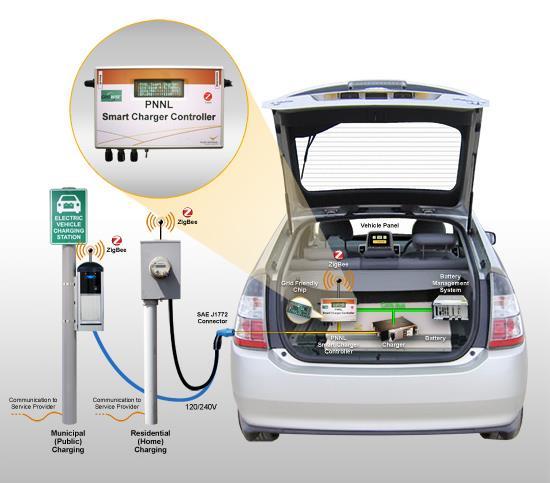

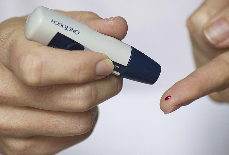


2 Electronic devices in your everyday life What makes these products examples of electronic devices? What are some things they have in common? 2


3 How do electronics communicate and manipulate information? How do devices like computers interpret human commands? How do electronic systems store information? How do they manipulation information? 3

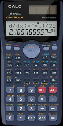
4 How do electronics communicate and manipulate information? How do devices like computers interpret human commands? Humans provide inputs through keyboards, mice, touchscreens, knobs, etc. Each of these inputs is built into the circuit Example: calculator circuit shown in the image How do electronic systems store information? Circuits can have different states based on whether: switches are on/off knobs are turned high/low voltages are high/low... How do electronic systems manipulate information? Logic is built into the circuit We will discuss this more shortly 4
, which")

5 Programs stored in computer memory Some electronics can be programmed to perform new tasks without rewiring. Humans provide instructions to computers using high-level languages (like Python, C, Java, Ruby, ), which are then translated into machine language. Machine language is often in binary a number system that only uses 0 and 1. Why binary? What do these 1s and 0s represent? High-level programming language Machine language 5
6 Binary (Base 2) 6
.")
7 Why use binary? Binary is a way to represent numbers using only 0 and 1. It s relatively easy and cheap to make circuit components that are either on or off (a two-state device). Computers are a combination of many, many such devices. 7
. A group of 1000 bytes is a kilobyte (KB). A group of 10 6 bytes is a megabyte (MB).")
8 Data size You are likely familiar with file sizes: kilobytes, megabytes, etc. What do those sizes represent? Each binary digit (0 or 1) is called a bit (b). A group of 8 bits is called a byte (B). A group of 1000 bytes is a kilobyte (KB). A group of 10 6 bytes is a megabyte (MB). A group of 10 9 bytes is a gigabyte (GB). 8
9 What is binary? Binary is a way to represent numbers using only 0 and 1. You are accustomed to the decimal system, which is base 10. There are 10 digits that represent all numbers (0, 1, 2, 3, 4, 5, 6, 7, 8, and 9). Binary is base 2, so it only has 2 digits (0 and 1). Consider the decimal system (base 10). What does each digit represent? 512 = 5 x x x = 5 x x x 1 Binary is base 2. Only digits are 0 and 1. Each digit in a number represents a power of 2. To distinguish between decimal and binary numbers, use 0b before the digits or use subscript 2 at the end = 0b10101 = 1 x x x x x 2 0 What decimal number is equal to? = 1 x x x x x 1 9

10 Quiz: binary and decimal 1. What is the largest decimal number we can represent with 8 binary digits? 2. How many binary digits do we need to represent the decimal number 55? 3. Which of these numbers are even? a b c d Convert 0b from binary to decimal. 5. Convert 123 from decimal to binary. 10


11 Limitations of binary Precision limitations, especially when we consider decimal and negative values Ex: How many bits are needed to represent a number between ? Discrete vs continuous (digital vs analog). Only limited number of buckets conversion from analog to digital sometimes loses information. (example above is rounded to two decimal places) 11
12 Analog vs digital Analog - Continuous Digital - Discrete Examples: Mercury thermometers Phonographs (vinyl records) Scale that uses a sliding weight Examples: Digital thermometer CDs Digital scale Benefits: Could have an infinite number of values May be higher quality (e.g. original painting vs digital photogram) Benefits: Can be stored and manipulated by computers Values are less ambiguous: If data starts to degrade, it may be possible to recover it Digital circuits are less susceptible to noise 12
13 Binary, octal, and hexadecimal Binary is base 2. Digits are 0 and 1. Each digit represents a power of = 1 x x x x x 2 0 = 21 Octal is base 8. Digits are 0, 1, 2, 3, 4, 5, 6, 7. Each digit represents a power of = 2 x x 8 0 = 21 Hexadecimal is base 16. Digits are 0, 1, 2, 3, 4, 5, 6, 7, 8, 9, A, B, C, D, E, F Each digit represents a power of = 1 x x 16 0 = 21 13


14 ASCII table Characters can be converted to numbers using conventions like the ASCII table. 14
15 Converting from binary to octal or hexadecimal Binary to octal group 3 bits (add leading zeros if needed) = = = 5 Binary to hexadecimal group 4 bits (add leading zeros if needed) = = = 5 15
16 Digital Boolean Logic 16

17 Analogy between devices, binary values, logic, and circuits In the following discussion we consider two-state inputs or outputs. Depending on the context, it may be helpful to consider the two options as off vs. on or false vs. true. Device Off On Binary 0 1 Logic False True Physical circuit Low voltage High voltage 17
18 Logic: AND Consider a device that should only perform an action (say, turn on a light) when Switch A and Switch B are both activated. What would that circuit look like? Lightbulb 1 2 AND Power supply Switch 1 Switch 2 Light Off Off Off On On Off On On 18
19 Logic: OR Consider a device that should only perform an action (say, turn on a light) when either Switch A or Switch B is activated. What would that circuit look like? Lightbulb 1 2 OR Power supply Switch 1 Switch 2 Light Off Off Off On On Off On On 19
20 Logic: NOT Consider a device that should only perform an action (say, turn on a light) when Switch A is not activated. What would that circuit look like? Lightbulb 1 NOT Switch 1 Off On Light Power supply 20

21 Logic gates: AND Logic gates are idealized representations of the AND, OR, and NOT actions you built with simple circuits. They are an abstract way to connect circuit inputs to circuit outputs. Switch 1 value Switch 2 value AND Lightbulb value 1 2 AND Input 1 Input 2 AND Output Switch 1 Switch 2 Light Off Off Off Off On Off On Off Off On On On Input 1 Input 2 Output Off Off Off Off On Off On Off Off On On On 21
22 Logic gates Input 1 Input 2 AND Output Input 1 Input 2 OR Output Input 1 Input 2 Output Off Off Off Off On Off On Off Off On On On Input 1 Input 2 Output Off Off Off Off On On On Off On On On On Input NOT Output Input Off On Output On Off 22
23 Logic gates Input 1 Input 2 AND Output Input 1 Input 2 OR Output Input 1 Input 2 Output Off Off Off Off On Off On Off Off On On On Input 1 Input 2 Output Off Off Off Off On On On Off On On On On Input 1 Input 2 NAND Output Input 1 Input 2 NOR Output Input 1 Input 2 Output Off Off On Off On On On Off On On On Off Input 1 Input 2 Output Off Off On Off On Off On Off Off On On Off 23


 are")
24 Integrated circuits Physically, logic gates are composed of transistors or diodes that act as switches, and they are often manufactured as part of integrated circuits. Notch Complementary metal-oxide-semiconductor (CMOS) devices (shown in the photo) are examples of integrated circuits. Example schematic 24
Why digital? Overview. Number Systems. Binary to Decimal conversion
 Why digital? Overview It has the following advantages over analog. It can be processed and transmitted efficiently and reliably. It can be stored and retrieved with greater accuracy. Noise level does not
12/31/2010. Digital Operations and Computations Course Notes. 01-Number Systems Text: Unit 1. Overview. What is a Digital System?
 Digital Operations and Computations Course Notes 0-Number Systems Text: Unit Winter 20 Professor H. Louie Department of Electrical & Computer Engineering Seattle University ECEGR/ISSC 20 Digital Operations
CS1800: Hex & Logic. Professor Kevin Gold
 CS1800: Hex & Logic Professor Kevin Gold Reviewing Last Time: Binary Last time, we saw that arbitrary numbers can be represented in binary. Each place in a binary number stands for a different power of
Introduction to digital systems. Juan P Bello
 Introduction to digital systems Juan P Bello Analogue vs Digital (1) Analog information is made up of a continuum of values within a given range At its most basic, digital information can assume only one
Digital Logic. CS211 Computer Architecture. l Topics. l Transistors (Design & Types) l Logic Gates. l Combinational Circuits.
 l Logic Gates. l Combinational Circuits.") CS211 Computer Architecture Digital Logic l Topics l Transistors (Design & Types) l Logic Gates l Combinational Circuits l K-Maps Figures & Tables borrowed from:! http://www.allaboutcircuits.com/vol_4/index.html!
CS211 Computer Architecture Digital Logic l Topics l Transistors (Design & Types) l Logic Gates l Combinational Circuits l K-Maps Figures & Tables borrowed from:! http://www.allaboutcircuits.com/vol_4/index.html!
Digital Systems Overview. Unit 1 Numbering Systems. Why Digital Systems? Levels of Design Abstraction. Dissecting Decimal Numbers
 Unit Numbering Systems Fundamentals of Logic Design EE2369 Prof. Eric MacDonald Fall Semester 2003 Digital Systems Overview Digital Systems are Home PC XBOX or Playstation2 Cell phone Network router Data
Advanced Information Storage 02
 dvanced Information Storage 02 tsufumi Hirohata Department of Electronics 16:00 10/October/2013 Thursday (V 120) Quick Review over the Last Lecture Von Neumann s model : Memory access : Bit / byte : 1
Cs302 Quiz for MID TERM Exam Solved
 Question # 1 of 10 ( Start time: 01:30:33 PM ) Total Marks: 1 Caveman used a number system that has distinct shapes: 4 5 6 7 Question # 2 of 10 ( Start time: 01:31:25 PM ) Total Marks: 1 TTL based devices
Unit 8A Computer Organization. Boolean Logic and Gates
 Unit 8A Computer Organization Boolean Logic and Gates Announcements Bring ear buds or headphones to lab! 15110 Principles of Computing, Carnegie Mellon University - CORTINA 2 Representing and Manipulating
Digital Systems Roberto Muscedere Images 2013 Pearson Education Inc. 1
 Digital Systems Digital systems have such a prominent role in everyday life The digital age The technology around us is ubiquitous, that is we don t even notice it anymore Digital systems are used in:
Week No. 06: Numbering Systems
 Week No. 06: Numbering Systems Numbering System: A numbering system defined as A set of values used to represent quantity. OR A number system is a term used for a set of different symbols or digits, which
of Digital Electronics
 26 Digital Electronics 729 Digital Electronics 26.1 Analog and Digital Signals 26.3 Binary Number System 26.5 Decimal to Binary Conversion 26.7 Octal Number System 26.9 Binary-Coded Decimal Code (BCD Code)
CS 226: Digital Logic Design
 CS 226: Digital Logic Design 0 1 1 I S 0 1 0 S Department of Computer Science and Engineering, Indian Institute of Technology Bombay. 1 of 29 Objectives In this lecture we will introduce: 1. Logic functions
Computer Organization: Boolean Logic
 Computer Organization: Boolean Logic Representing and Manipulating Data Last Unit How to represent data as a sequence of bits How to interpret bit representations Use of levels of abstraction in representing
Binary addition example worked out
 Binary addition example worked out Some terms are given here Exercise: what are these numbers equivalent to in decimal? The initial carry in is implicitly 0 1 1 1 0 (Carries) 1 0 1 1 (Augend) + 1 1 1 0
Students should be able to (a) produce a truth table from a given logic diagram
 produce a truth table from a given logic diagram") Truth tables Teacher s Notes Lesson Plan Length 60 mins Specification Link 2.1.2/f inary logic Learning objective Students should be able to (a) produce a truth table from a given logic diagram Time (min)
Truth tables Teacher s Notes Lesson Plan Length 60 mins Specification Link 2.1.2/f inary logic Learning objective Students should be able to (a) produce a truth table from a given logic diagram Time (min)
E40M. Binary Numbers. M. Horowitz, J. Plummer, R. Howe 1
 E40M Binary Numbers M. Horowitz, J. Plummer, R. Howe 1 Reading Chapter 5 in the reader A&L 5.6 M. Horowitz, J. Plummer, R. Howe 2 Useless Box Lab Project #2 Adding a computer to the Useless Box alows us
Number System. Decimal to binary Binary to Decimal Binary to octal Binary to hexadecimal Hexadecimal to binary Octal to binary
 Number System Decimal to binary Binary to Decimal Binary to octal Binary to hexadecimal Hexadecimal to binary Octal to binary BOOLEAN ALGEBRA BOOLEAN LOGIC OPERATIONS Logical AND Logical OR Logical COMPLEMENTATION
Mark Redekopp, All rights reserved. Lecture 1 Slides. Intro Number Systems Logic Functions
 Lecture Slides Intro Number Systems Logic Functions EE 0 in Context EE 0 EE 20L Logic Design Fundamentals Logic Design, CAD Tools, Lab tools, Project EE 357 EE 457 Computer Architecture Using the logic
School of Computer Science and Electrical Engineering 28/05/01. Digital Circuits. Lecture 14. ENG1030 Electrical Physics and Electronics
 Digital Circuits 1 Why are we studying digital So that one day you can design something which is better than the... circuits? 2 Why are we studying digital or something better than the... circuits? 3 Why
Switches: basic element of physical implementations
 Combinational logic Switches Basic logic and truth tables Logic functions Boolean algebra Proofs by re-writing and by perfect induction Winter 200 CSE370 - II - Boolean Algebra Switches: basic element
Boolean algebra. Examples of these individual laws of Boolean, rules and theorems for Boolean algebra are given in the following table.
 The Laws of Boolean Boolean algebra As well as the logic symbols 0 and 1 being used to represent a digital input or output, we can also use them as constants for a permanently Open or Closed circuit or
Digital Circuits. 1. Inputs & Outputs are quantized at two levels. 2. Binary arithmetic, only digits are 0 & 1. Position indicates power of 2.
 Digital Circuits 1. Inputs & Outputs are quantized at two levels. 2. inary arithmetic, only digits are 0 & 1. Position indicates power of 2. 11001 = 2 4 + 2 3 + 0 + 0 +2 0 16 + 8 + 0 + 0 + 1 = 25 Digital
Intro To Digital Logic
 Intro To Digital Logic 1 Announcements... Project 2.2 out But delayed till after the midterm Midterm in a week Covers up to last lecture + next week's homework & lab Nick goes "H-Bomb of Justice" About
Logic Theory in Designing of Digital Circuit & Microprocessor
 Logic Theory in Designing of Digital Circuit & Microprocessor Prof.Vikram Mahendra Kakade Assistant Professor, Electronics & Telecommunication Engineering Department, Prof Ram Meghe College of Engineering
ENGIN 112 Intro to Electrical and Computer Engineering
 ENGIN 112 Intro to Electrical and Computer Engineering Lecture 2 Number Systems Russell Tessier KEB 309 G tessier@ecs.umass.edu Overview The design of computers It all starts with numbers Building circuits
Information Storage and Spintronics 02
 Information Storage and Spintronics 02 tsufumi Hirohata Department of Electronic Engineering 09:00 Tuesday, 02/October/2018 (J/Q 004) Contents of Information Storage and Spintronics Lectures : tsufumi
10/14/2009. Reading: Hambley Chapters
 EE40 Lec 14 Digital Signal and Boolean Algebra Prof. Nathan Cheung 10/14/2009 Reading: Hambley Chapters 7.1-7.4 7.4 Slide 1 Analog Signals Analog: signal amplitude is continuous with time. Amplitude Modulated
Counting, symbols, positions, powers, choice, arithmetic, binary, translation, hex, addresses, and gates.
 Counting, symbols, positions, powers, choice, arithmetic, binary, translation, he, addresses, and gates. Counting. Suppose the concern is a collection of objects. As an eample, let the objects be denoted
CPE100: Digital Logic Design I
 Chapter 1 Professor Brendan Morris, SEB 3216, brendan.morris@unlv.edu http://www.ee.unlv.edu/~b1morris/cpe100/ CPE100: Digital Logic Design I Section 1004: Dr. Morris From Zero to One Chapter 1 Background:
1 Computing System 2. 2 Data Representation Number Systems 22
 Chapter 4: Computing System & Data Representation Christian Jacob 1 Computing System 2 1.1 Abacus 3 2 Data Representation 19 3 Number Systems 22 3.1 Important Number Systems for Computers 24 3.2 Decimal
Contents. Chapter 2 Digital Circuits Page 1 of 30
 Chapter 2 Digital Circuits Page 1 of 30 Contents Contents... 1 2 Digital Circuits... 2 2.1 Binary Numbers... 2 2.2 Binary Switch... 4 2.3 Basic Logic Operators and Logic Expressions... 5 2.4 Truth Tables...
Introduction to Computer Engineering. CS/ECE 252, Fall 2012 Prof. Guri Sohi Computer Sciences Department University of Wisconsin Madison
 Introduction to Computer Engineering CS/ECE 252, Fall 2012 Prof. Guri Sohi Computer Sciences Department University of Wisconsin Madison Chapter 3 Digital Logic Structures Slides based on set prepared by
Chapter 1 :: From Zero to One
 Chapter 1 :: From Zero to One Digital Design and Computer Architecture David Money Harris and Sarah L. Harris Copyright 2007 Elsevier 1- Chapter 1 :: Topics Background The Game Plan The Art of Managing
0 volts. 2 volts. 5 volts
 CS101 Binary Storage Devices and Boolean Logic Now that we have discussed number representation, why do computers use the binary representation and not something we are more familiar with, like decimal?
Implementation of Boolean Logic by Digital Circuits
 Implementation of Boolean Logic by Digital Circuits We now consider the use of electronic circuits to implement Boolean functions and arithmetic functions that can be derived from these Boolean functions.
Section 1A. Introduction & Basic Principles. Engineering Areas
 ection 1 Introduction & asic Principles Engineering Measurements Engineering reas Research & Development Process Control Fabrication Manufacturing ervice & Maintenance Engineering Measurements 1 2 Engineering
Signals and Systems Digital Logic System
 Signals and Systems Digital Logic System Prof. Wonhee Kim Chapter 2 Design Process for Combinational Systems Step 1: Represent each of the inputs and outputs in binary Step 1.5: If necessary, break the
Introduction to CMOS VLSI Design Lecture 1: Introduction
 Introduction to CMOS VLSI Design Lecture 1: Introduction David Harris, Harvey Mudd College Kartik Mohanram and Steven Levitan University of Pittsburgh Introduction Integrated circuits: many transistors
Fundamentals of Digital Design
 Fundamentals of Digital Design Digital Radiation Measurement and Spectroscopy NE/RHP 537 1 Binary Number System The binary numeral system, or base-2 number system, is a numeral system that represents numeric
Lecture 22 Chapters 3 Logic Circuits Part 1
 Lecture 22 Chapters 3 Logic Circuits Part 1 LC-3 Data Path Revisited How are the components Seen here implemented? 5-2 Computing Layers Problems Algorithms Language Instruction Set Architecture Microarchitecture
Number System conversions
 Number System conversions Number Systems The system used to count discrete units is called number system. There are four systems of arithmetic which are often used in digital electronics. Decimal Number
SAU1A FUNDAMENTALS OF DIGITAL COMPUTERS
 SAU1A FUNDAMENTALS OF DIGITAL COMPUTERS Unit : I - V Unit : I Overview Fundamentals of Computers Characteristics of Computers Computer Language Operating Systems Generation of Computers 2 Definition of
Chapter 2: Boolean Algebra and Logic Gates
 Chapter 2: Boolean Algebra and Logic Gates Mathematical methods that simplify binary logics or circuits rely primarily on Boolean algebra. Boolean algebra: a set of elements, a set of operators, and a
Chapter 1. Binary Systems 1-1. Outline. ! Introductions. ! Number Base Conversions. ! Binary Arithmetic. ! Binary Codes. ! Binary Elements 1-2
 Chapter 1 Binary Systems 1-1 Outline! Introductions! Number Base Conversions! Binary Arithmetic! Binary Codes! Binary Elements 1-2 3C Integration 傳輸與介面 IA Connecting 聲音與影像 Consumer Screen Phone Set Top
Computer Science. 19. Combinational Circuits. Computer Science COMPUTER SCIENCE. Section 6.1.
 COMPUTER SCIENCE S E D G E W I C K / W A Y N E PA R T I I : A L G O R I T H M S, M A C H I N E S, a n d T H E O R Y Computer Science Computer Science An Interdisciplinary Approach Section 6.1 ROBERT SEDGEWICK
Introduction to Computer Engineering ECE 203
 Introduction to Computer Engineering ECE 203 Northwestern University Department of Electrical Engineering and Computer Science Teacher: Robert Dick Office: L477 Tech Email: dickrp@ece.northwestern.edu
CSC9R6 Computer Design. Practical Digital Logic
 CSC9R6 Computer Design Practical Digital Logic 1 References (for this part of CSC9R6) Hamacher et al: Computer Organization App A. In library Floyd: Digital Fundamentals Ch 1, 3-6, 8-10 web page: www.prenhall.com/floyd/
Z = F(X) Combinational circuit. A combinational circuit can be specified either by a truth table. Truth Table
 Combinational circuit. A combinational circuit can be specified either by a truth table. Truth Table") Lesson Objectives In this lesson, you will learn about What are combinational circuits Design procedure of combinational circuits Examples of combinational circuit design Combinational Circuits Logic circuit
Lesson Objectives In this lesson, you will learn about What are combinational circuits Design procedure of combinational circuits Examples of combinational circuit design Combinational Circuits Logic circuit
CMPE12 - Notes chapter 1. Digital Logic. (Textbook Chapter 3)
") CMPE12 - Notes chapter 1 Digital Logic (Textbook Chapter 3) Transistor: Building Block of Computers Microprocessors contain TONS of transistors Intel Montecito (2005): 1.72 billion Intel Pentium 4 (2000):
CMPE12 - Notes chapter 1 Digital Logic (Textbook Chapter 3) Transistor: Building Block of Computers Microprocessors contain TONS of transistors Intel Montecito (2005): 1.72 billion Intel Pentium 4 (2000):
ENG2410 Digital Design Introduction to Digital Systems. Fall 2017 S. Areibi School of Engineering University of Guelph
 ENG2410 Digital Design Introduction to Digital Systems Fall 2017 S. Areibi School of Engineering University of Guelph Resources Chapter #1, Mano Sections 1.1 Digital Computers 1.2 Number Systems 1.3 Arithmetic
Digital electronic systems are designed to process voltage signals which change quickly between two levels. Low time.
 DIGITL ELECTRONIC SYSTEMS Digital electronic systems are designed to process voltage signals which change quickly between two levels. High Voltage Low time Fig. 1 digital signal LOGIC GTES The TTL digital
Computer organization
 Computer organization Levels of abstraction Assembler Simulator Applications C C++ Java High-level language SOFTWARE add lw ori Assembly language Goal 0000 0001 0000 1001 0101 Machine instructions/data
CSEN102 Introduction to Computer Science
 CSEN102 Introduction to Computer Science Lecture 7: Representing Information I Prof. Dr. Slim Abdennadher Dr. Mohammed Salem, slim.abdennadher@guc.edu.eg, mohammed.salem@guc.edu.eg German University Cairo,
Numbering Systems. Contents: Binary & Decimal. Converting From: B D, D B. Arithmetic operation on Binary.
 Numbering Systems Contents: Binary & Decimal. Converting From: B D, D B. Arithmetic operation on Binary. Addition & Subtraction using Octal & Hexadecimal 2 s Complement, Subtraction Using 2 s Complement.
Floating Point Representation and Digital Logic. Lecture 11 CS301
 Floating Point Representation and Digital Logic Lecture 11 CS301 Administrative Daily Review of today s lecture w Due tomorrow (10/4) at 8am Lab #3 due Friday (9/7) 1:29pm HW #5 assigned w Due Monday 10/8
4 Switching Algebra 4.1 Axioms; Signals and Switching Algebra
 4 Switching Algebra 4.1 Axioms; Signals and Switching Algebra To design a digital circuit that will perform a required function, it is necessary to manipulate and combine the various input signals in certain
CS/COE0447: Computer Organization and Assembly Language
 CS/COE0447: Computer Organization and Assembly Language Logic Design Introduction (Brief?) Appendix B: The Basics of Logic Design Dept. of Computer Science Logic design? Digital hardware is implemented
UNIVERSITI TENAGA NASIONAL. College of Information Technology
 UNIVERSITI TENAGA NASIONAL College of Information Technology BACHELOR OF COMPUTER SCIENCE (HONS.) FINAL EXAMINATION SEMESTER 2 2012/2013 DIGITAL SYSTEMS DESIGN (CSNB163) January 2013 Time allowed: 3 hours
CPE100: Digital Logic Design I
 Professor Brendan Morris, SEB 3216, brendan.morris@unlv.edu CPE100: Digital Logic Design I Midterm01 Review http://www.ee.unlv.edu/~b1morris/cpe100/ 2 Logistics Thursday Oct. 5 th In normal lecture (13:00-14:15)
- Why aren t there more quantum algorithms? - Quantum Programming Languages. By : Amanda Cieslak and Ahmana Tarin
 - Why aren t there more quantum algorithms? - Quantum Programming Languages By : Amanda Cieslak and Ahmana Tarin Why aren t there more quantum algorithms? there are only a few problems for which quantum
CpE358/CS381. Switching Theory and Logical Design. Summer
 Switching Theory and Logical Design - Class Schedule Monday Tuesday Wednesday Thursday Friday May 7 8 9 - Class 2 - Class 2 2 24 - Class 3 25 26 - Class 4 27 28 Quiz Commencement 3 June 2 - Class 5 3 -
University of Florida EEL 3701 Summer 2015 Dr. Eric. M. Schwartz Department of Electrical & Computer Engineering Tuesday, 30 June 2015
 University of Florida EEL 3701 Summer 2015 Dr Eric M Schwartz Page 1/13 Exam 1 May the Schwartz be with you! Instructions: Turn off all cell phones and other noise making devices Show all work on the front
University of Florida EEL 3701 Fall 2014 Dr. Eric. M. Schwartz Department of Electrical & Computer Engineering Wednesday, 15 October 2014
 Page 1/12 Exam 1 May the Schwartz Instructions: be with you! Turn off all cell phones and other noise making devices and put away all electronics Show all work on the front of the test papers Box each
Hakim Weatherspoon CS 3410 Computer Science Cornell University
 Hakim Weatherspoon CS 3410 Computer Science Cornell University The slides are the product of many rounds of teaching CS 3410 by Professors Weatherspoon, Bala, Bracy, and Sirer. memory inst 32 register
Digital Logic (2) Boolean Algebra
 Boolean Algebra") Digital Logic (2) Boolean Algebra Boolean algebra is the mathematics of digital systems. It was developed in 1850 s by George Boole. We will use Boolean algebra to minimize logic expressions. Karnaugh
Digital Logic (2) Boolean Algebra Boolean algebra is the mathematics of digital systems. It was developed in 1850 s by George Boole. We will use Boolean algebra to minimize logic expressions. Karnaugh
Lecture 4 Modeling, Analysis and Simulation in Logic Design. Dr. Yinong Chen
 Lecture 4 Modeling, Analysis and Simulation in Logic Design Dr. Yinong Chen The Engineering Design Process Define Problem and requirement Research Define Alternative solutions CAD Modeling Analysis Simulation
Building a Computer Adder
 Logic Gates are used to translate Boolean logic into circuits. In the abstract it is clear that we can build AND gates that perform the AND function and OR gates that perform the OR function and so on.
Unit II Chapter 4:- Digital Logic Contents 4.1 Introduction... 4
 Unit II Chapter 4:- Digital Logic Contents 4.1 Introduction... 4 4.1.1 Signal... 4 4.1.2 Comparison of Analog and Digital Signal... 7 4.2 Number Systems... 7 4.2.1 Decimal Number System... 7 4.2.2 Binary
Simple Interactions CS 105 Lecture 2 Jan 26. Matthew Stone
 Simple Interactions CS 105 Lecture 2 Jan 26 Matthew Stone Rutgers University Department of Computer Science and Center for Cognitive Science Themes from the Preface 2 Computers are multimedia devices Text
Boolean Algebra. The Building Blocks of Digital Logic Design. Section. Section Overview. Binary Operations and Their Representation.
 Section 3 Boolean Algebra The Building Blocks of Digital Logic Design Section Overview Binary Operations (AND, OR, NOT), Basic laws, Proof by Perfect Induction, De Morgan s Theorem, Canonical and Standard
CPE100: Digital Logic Design I
 Chapter 1 Professor Brendan Morris, SEB 3216, brendan.morris@unlv.edu http://www.ee.unlv.edu/~b1morris/cpe100/ CPE100: Digital Logic Design I Section 1004: Dr. Morris From Zero to One Chapter 1 Background:
CHAPTER 2 NUMBER SYSTEMS
 CHAPTER 2 NUMBER SYSTEMS The Decimal Number System : We begin our study of the number systems with the familiar decimal number system. The decimal system contains ten unique symbol 0, 1, 2, 3, 4, 5, 6,
Gates and Logic: From Transistors to Logic Gates and Logic Circuits
 Gates and Logic: From Transistors to Logic Gates and Logic Circuits Prof. Hakim Weatherspoon CS 3410 Computer Science Cornell University The slides are the product of many rounds of teaching CS 3410 by
Review for Test 1 : Ch1 5
 Review for Test 1 : Ch1 5 October 5, 2006 Typeset by FoilTEX Positional Numbers 527.46 10 = (5 10 2 )+(2 10 1 )+(7 10 0 )+(4 10 1 )+(6 10 2 ) 527.46 8 = (5 8 2 ) + (2 8 1 ) + (7 8 0 ) + (4 8 1 ) + (6 8
CSE370: Introduction to Digital Design
 CSE370: Introduction to Digital Design Course staff Gaetano Borriello, Brian DeRenzi, Firat Kiyak Course web www.cs.washington.edu/370/ Make sure to subscribe to class mailing list (cse370@cs) Course text
XI STANDARD [ COMPUTER SCIENCE ] 5 MARKS STUDY MATERIAL.
![XI STANDARD [ COMPUTER SCIENCE ] 5 MARKS STUDY MATERIAL.](/thumbs/81/84726747.jpg "XI STANDARD [ COMPUTER SCIENCE ] 5 MARKS STUDY MATERIAL.") 2017-18 XI STANDARD [ COMPUTER SCIENCE ] 5 MARKS STUDY MATERIAL HALF ADDER 1. The circuit that performs addition within the Arithmetic and Logic Unit of the CPU are called adders. 2. A unit that adds two
2017-18 XI STANDARD [ COMPUTER SCIENCE ] 5 MARKS STUDY MATERIAL HALF ADDER 1. The circuit that performs addition within the Arithmetic and Logic Unit of the CPU are called adders. 2. A unit that adds two
We say that the base of the decimal number system is ten, represented by the symbol
 Introduction to counting and positional notation. In the decimal number system, a typical number, N, looks like... d 3 d 2 d 1 d 0.d -1 d -2 d -3... [N1] where the ellipsis at each end indicates that there
COMBINATIONAL LOGIC CIRCUITS. Dr. Mudathir A. Fagiri
 COMBINATIONAL LOGIC CIRCUITS Dr. Mudathir A. Fagiri Standard Combinational Modules Decoder: Decode address Encoder: Encode address Multiplexer (Mux): Select data by address Demultiplexier (DeMux): Direct
CHAPTER 7. Exercises 17/ / /2 2 0
 CHAPTER 7 Exercises E7. (a) For the whole part, we have: Quotient Remainders 23/2 /2 5 5/2 2 2/2 0 /2 0 Reading the remainders in reverse order, we obtain: 23 0 = 0 2 For the fractional part we have 2
Digital Logic and Design (Course Code: EE222) Lecture 1 5: Digital Electronics Fundamentals. Evolution of Electronic Devices
 Lecture 1 5: Digital Electronics Fundamentals. Evolution of Electronic Devices") Indian Institute of Technolog Jodhpur, Year 207 208 Digital Logic and Design (Course Code: EE222) Lecture 5: Digital Electronics Fundamentals Course Instructor: Shree Prakash Tiwari Email: sptiwari@iitj.ac.in
Indian Institute of Technolog Jodhpur, Year 207 208 Digital Logic and Design (Course Code: EE222) Lecture 5: Digital Electronics Fundamentals Course Instructor: Shree Prakash Tiwari Email: sptiwari@iitj.ac.in
Organisasi dan Arsitektur Komputer L#1: Fundamental Concepts Amil A. Ilham
 Organisasi dan Arsitektur Komputer http://www.unhas.ac.id/amil/stmik2016/arsikom/ L#1: Fundamental Concepts Amil A. Ilham http://www.unhas.ac.id/amil Administrasi Kuliah ADMINISTRASI KULIAH 2 Penilaian
Lecture 7: Logic design. Combinational logic circuits
 /24/28 Lecture 7: Logic design Binary digital circuits: Two voltage levels: and (ground and supply voltage) Built from transistors used as on/off switches Analog circuits not very suitable for generic
LOGIC GATES. Basic Experiment and Design of Electronics. Ho Kyung Kim, Ph.D.
 Basic Eperiment and Design of Electronics LOGIC GATES Ho Kyung Kim, Ph.D. hokyung@pusan.ac.kr School of Mechanical Engineering Pusan National University Outline Boolean algebra Logic gates Karnaugh maps
Chapter 7. Sequential Circuits Registers, Counters, RAM
 Chapter 7. Sequential Circuits Registers, Counters, RAM Register - a group of binary storage elements suitable for holding binary info A group of FFs constitutes a register Commonly used as temporary storage
Numbers and Arithmetic
 Numbers and Arithmetic See: P&H Chapter 2.4 2.6, 3.2, C.5 C.6 Hakim Weatherspoon CS 3410, Spring 2013 Computer Science Cornell University Big Picture: Building a Processor memory inst register file alu
Outline. policies for the first part. with some potential answers... MCS 260 Lecture 10.0 Introduction to Computer Science Jan Verschelde, 9 July 2014
 Outline 1 midterm exam on Friday 11 July 2014 policies for the first part 2 questions with some potential answers... MCS 260 Lecture 10.0 Introduction to Computer Science Jan Verschelde, 9 July 2014 Intro
COSC 243. Introduction to Logic And Combinatorial Logic. Lecture 4 - Introduction to Logic and Combinatorial Logic. COSC 243 (Computer Architecture)
") COSC 243 Introduction to Logic And Combinatorial Logic 1 Overview This Lecture Introduction to Digital Logic Gates Boolean algebra Combinatorial Logic Source: Chapter 11 (10 th edition) Source: J.R. Gregg,
COSC 243 Introduction to Logic And Combinatorial Logic 1 Overview This Lecture Introduction to Digital Logic Gates Boolean algebra Combinatorial Logic Source: Chapter 11 (10 th edition) Source: J.R. Gregg,
T02 Tutorial Slides for Week 6
 T02 Tutorial Slides for Week 6 ENEL 353: Digital Circuits Fall 2017 Term Steve Norman, PhD, PEng Electrical & Computer Engineering Schulich School of Engineering University of Calgary 17 October, 2017
UNIVERSITY OF BOLTON SCHOOL OF ENGINEERING BENG (HONS) ELECTRICAL & ELECTRONICS ENGINEERING EXAMINATION SEMESTER /2017
 ELECTRICAL & ELECTRONICS ENGINEERING EXAMINATION SEMESTER /2017") UNIVERSITY OF BOLTON TW35 SCHOOL OF ENGINEERING BENG (HONS) ELECTRICAL & ELECTRONICS ENGINEERING EXAMINATION SEMESTER 2-2016/2017 INTERMEDIATE DIGITAL ELECTRONICS AND COMMUNICATIONS MODULE NO: EEE5002
UNIVERSITY OF BOLTON TW35 SCHOOL OF ENGINEERING BENG (HONS) ELECTRICAL & ELECTRONICS ENGINEERING EXAMINATION SEMESTER 2-2016/2017 INTERMEDIATE DIGITAL ELECTRONICS AND COMMUNICATIONS MODULE NO: EEE5002
DIGITAL LOGIC CIRCUITS
 DIGITAL LOGIC CIRCUITS Introduction Logic Gates Boolean Algebra Map Specification Combinational Circuits Flip-Flops Sequential Circuits Memory Components Integrated Circuits Digital Computers 2 LOGIC GATES
2.0 Basic Elements of a Quantum Information Processor. 2.1 Classical information processing The carrier of information
 QSIT09.L03 Page 1 2.0 Basic Elements of a Quantum Information Processor 2.1 Classical information processing 2.1.1 The carrier of information - binary representation of information as bits (Binary digits).
Gates and Logic: From Transistors to Logic Gates and Logic Circuits
 Gates and Logic: From Transistors to Logic Gates and Logic Circuits Prof. Hakim Weatherspoon CS 3410 Computer Science Cornell University The slides are the product of many rounds of teaching CS 3410 by
Applications. Smartphone, tablet, game controller, antilock brakes, microprocessor, Wires
 COMPUTER SCIENCE Combinational circuits Q. What is a combinational circuit? A. A digital circuit (all signals are or ) with no feedback (no loops). analog circuit: signals vary continuously sequential
Computer Science. 20. Combinational Circuits. Computer Science COMPUTER SCIENCE. Section
 COMPUTER SCIENCE S E D G E W I C K / W A Y N E Computer Science 20. Combinational Circuits Computer Science An Interdisciplinary Approach Section 6.1 ROBERT SEDGEWICK K E V I N WAY N E http://introcs.cs.princeton.edu
Midterm Examination # 1 Wednesday, February 25, Duration of examination: 75 minutes
 Page 1 of 10 School of Computer Science 60-265-01 Computer Architecture and Digital Design Winter 2009 Semester Midterm Examination # 1 Wednesday, February 25, 2009 Student Name: First Name Family Name
Electronic Devices and Circuits Lecture 15 - Digital Circuits: Inverter Basics - Outline Announcements. = total current; I D
 6.012 - Electronic Devices and Circuits Lecture 15 - Digital Circuits: Inverter asics - Outline Announcements Handout - Lecture Outline and Summary The MOSFET alpha factor - use definition in lecture,
Chapter 4: Combinational Logic Solutions to Problems: [1, 5, 9, 12, 19, 23, 30, 33]
![Chapter 4: Combinational Logic Solutions to Problems: [1, 5, 9, 12, 19, 23, 30, 33]](/thumbs/81/84077758.jpg "Chapter 4: Combinational Logic Solutions to Problems: [1, 5, 9, 12, 19, 23, 30, 33]") Chapter 4: Combinational Logic Solutions to Problems: [, 5, 9, 2, 9, 23, 3, 33] Problem: 4- Consider the combinational circuit shown in Fig. P4-. (a) Derive the Boolean expressions for T through T 4. Evaluate
Chapter 4: Combinational Logic Solutions to Problems: [, 5, 9, 2, 9, 23, 3, 33] Problem: 4- Consider the combinational circuit shown in Fig. P4-. (a) Derive the Boolean expressions for T through T 4. Evaluate
DESIGN AND IMPLEMENTATION OF ENCODERS AND DECODERS. To design and implement encoders and decoders using logic gates.
 DESIGN AND IMPLEMENTATION OF ENCODERS AND DECODERS AIM To design and implement encoders and decoders using logic gates. COMPONENTS REQUIRED S.No Components Specification Quantity 1. Digital IC Trainer