Signals and Systems Digital Logic System
|
|
|
- Susanna Farmer
- 6 years ago
- Views:
Transcription
1 Signals and Systems Digital Logic System Prof. Wonhee Kim Chapter 2
2 Design Process for Combinational Systems Step 1: Represent each of the inputs and outputs in binary Step 1.5: If necessary, break the problem into smaller subproblems Step 2: Formalize the design specification either in the form of a truth table or of an algebraic expression Step 3: Simplify the description Step 4: Implement the system with the available components Digital input System Digital output 2

 It does not matter what output is when a =1 and b = 1")
3 Design Process for Combinational Systems 1: High, High voltage, True 0: Low, Low voltage, False X: Don t care It does not matter what output is when a and b are inputted ex) It does not matter what output is when a =1 and b = 1 3
4 Design Process for Combinational Systems CE1) A system with four inputs, A, B, C, and D, and one output, Z, such that Z=1 iff three of the input are 1. Input A Input B Input C Input D System Output Z 4
5 Design Process for Combinational Systems CE1) A system with four inputs, A, B, C, and D, and one output, Z, such that Z=1 iff three of the input are 1. Concern: Only three ones? 5
6 Design Process for Combinational Systems CE2) A single light (that can be on or off) that can be controlled by any one of three switches. One switch is the master on/off switch. If it is down, the light is off. When the master switch is up, a change in the position of one of the other switches (from up to down or from down to up) will cause the light to change state. Input A (Master) Input B Input C System Output Z 6
7 Design Process for Combinational Systems CE2) A single light (that can be on or off) that can be controlled by any one of three switches. One switch is the master on/off switch. If it is down, the light is off. When the master switch is up, a change in the position of one of the other switches (from up to down or from down to up) will cause the light to change state. 7
8 Design Process for Combinational Systems CE3) A system to do 1 bit of binary addition. It has three inputs (the 2 bits to be added plus the carry from the next lower order bit) and produces two outputs: a sum bit and a carry to the next higher order position. a b c in System c out s 8
9 Design Process for Combinational Systems CE3) A system to do 1 bit of binary addition. It has three inputs (the 2 bits to be added plus the carry from the next lower order bit) and produces two outputs: a sum bit and a carry to the next higher order position. 9
10 Design Process for Combinational Systems CE4) A display driver; a system that has as its input the code for a decimal digit and produces as its output the signals to drive a seven-segment display, such as those on most digital watches and numeric displays. 10
11 Design Process for Combinational Systems CE4) A display driver; a system that has as its input the code for a decimal digit and produces as its output the signals to drive a seven-segment display, such as those on most digital watches and numeric displays. 11
12 Design Process for Combinational Systems CE5) A system with nine inputs, representing two 4-bit binary numbers and a carry input, and one 5-bit output, representing the sum. (Each input number can range from 0 to 15; the output can range from 0 to 31.) 12
13 Switching Algebra Boolean Algebra: Use 0 (false) or 1 (true). Switching circuit: Use 0 (false) or 1 (true). High or low voltage Digital input Two valued switching circuits Digital output 1) OR (written as +) a + b (read a OR b) is 1 if and only if a = 1 or b = 1 or both 2) AND (written as or simply two variables catenated) a b = ab (read a AND b) is 1 if and only if a = 1 and b = 1 3) NOT (written ') a' (read NOT a) is 1 if and only if a = 0 13

14 Switching Algebra 14
15 Switching Algebra Example if A=B=C=1 and D=E=0, then 15
16 Switching Algebra True table example 16
17 Switching Algebra AND gate used in industries AND gate 17
18 Basic Properties of Switching Algebra 18
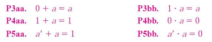
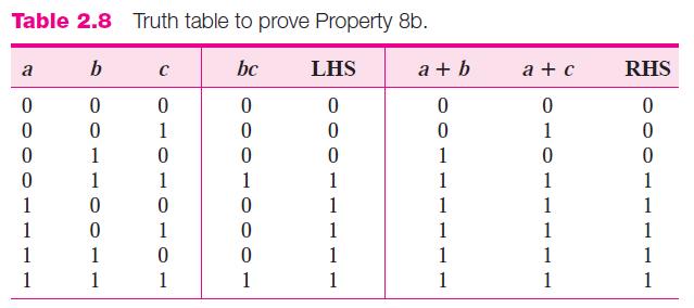
19 Basic Properties of Switching Algebra 19
20 Basic Properties of Switching Algebra 20
21 Manipulation of Algebraic Functions Literal Appearance of a variable or its complement Determining the complexity of an expression Ex) a, b' Ex) ab' + bc'd + a'd + e': 8 literals Product term One or more literals connected by AND operators Single literal is a product term Ex) ab', bc'd, a'd, e' Ex) ab' + bc'd + a'd + e': 4 product terms Standard product term (Miniterm) Product term that includes each variable of the problem Ex) For w,x,y, and z, w'xyz'and wxyz are standard product terms, but wy'z is not. 21
22 Manipulation of Algebraic Functions Sum of products expression (SOP) One or more product terms connected by OR operators Ex) ab' + bc'd + a'd + e' Canonical sum (Sum of standard product terms) Just a sum of products expression where all of the terms are standard product terms Ex) w'xyz' + wx'y'z' + wx'yz + wxyz (O) x + w'y + wxy'z (X) x' + y + z (X) Minimum sum of products expression One of those SOP expressions for a function that has the fewest number of product terms. 22
23 Manipulation of Algebraic Functions Minima 23
24 Manipulation of Algebraic Functions Not minima! 24
25 Manipulation of Algebraic Functions Sum term One or more literals connected by OR operators Ex) a + b, a' + b Standard sum term (Maxterm) Sum term that includes each variable of the problem Ex) For w,x,y, and z, w' + x + y + z' Product of sums expression (POS) One or more sum terms connected by AND operators Ex) (w + x)(w + y) 2 terms w(x + y) 2 terms w 1 term Canonical product, or product of standard sum terms Just a POS expression in which all of the terms are standard sum terms Minimum product of sums expression 25
26 Manipulation of Algebraic Functions Example) SOP POS Both x ' y + xy ' + xyz (x + y ')(x ' + y)(x + z ) x ' + y + z or xyz' Neither x(w' + yz) or z' + wx'y + v (xz + w ) 26
27 Implementation of Functions with AND, OR, AND NOT Gates f = xyz + xyz + xyz+ xyz+ xyz 27 two-level circuit
28 Implementation of Functions with AND, OR, AND NOT Gates Minima (SOP): f = xy+ xy + x z three-level circuit 28
29 Implementation of Functions with AND, OR, AND NOT Gates POS: f = (x + y)(x + y+ z) 29
30 Implementation of Functions with AND, OR, AND NOT Gates h = z+ wxy + v(xz + w) 30
31 Implementation of Functions with AND, OR, AND NOT Gates f = xy + xy + x z f = xy + x(y + z) 31
32 Implementation of Functions with AND, OR, AND NOT Gates IC used in industries 7404: 6(hex) NOT gates 7408: 4(quadruple) 2-input AND 게이트 7411: 3(triple) 3-input AND 게이트 7421: 2(dual) 4-input AND 게이트 7432: 4(quadruple) 2-input OR 게이트 32
33 Implementation of Functions with AND, OR, AND NOT Gates 33

34 Implementation of Functions with AND, OR, AND NOT Gates 34
35 Implementation of Functions with AND, OR, AND NOT Gates 35
36 From the Truth Table to Algebraic Expression f = ab + ab + ab = a+ab = a+b 36

37 From the Truth Table to Algebraic Expression 37

38 From the Truth Table to Algebraic Expression 38
39 From the Truth Table to Algebraic Expression 39
40 From the Truth Table to Algebraic Expression 40
41 From the Truth Table to Algebraic Expression CE1) A system with four inputs, A, B, C, and D, and one output, Z, such that Z=1 iff three of the input are 1. 41
42 From the Truth Table to Algebraic Expression CE2) A single light (that can be on or off) that can be controlled by any one of three switches. One switch is the master on/off switch. If it is down, the light is off. When the master switch is up, a change in the position of one of the other switches (from up to down or from down to up) will cause the light to change state. 42
 and produces two outputs: a sum bit and a")
43 From the Truth Table to Algebraic Expression CE3) A system to do 1 bit of binary addition. It has three inputs (the 2 bits to be added plus the carry from the next lower order bit) and produces two outputs: a sum bit and a carry to the next higher order position. 43

44 From the Truth Table to Algebraic Expression 44

45 From the Truth Table to Algebraic Expression 45
46 NAND, NOR, AND Exclusive-OR Gates 46
47 NAND, NOR, AND Exclusive-OR Gates 47
48 NAND, NOR, AND Exclusive-OR Gates The most important reason is that with either NAND or NOR, only one type of gate is required. These operators are said to be functionally complete. 48
49 NAND, NOR, AND Exclusive-OR Gates 49
50 NAND, NOR, AND Exclusive-OR Gates 50
51 NAND, NOR, AND Exclusive-OR Gates 51
52 NAND, NOR, AND Exclusive-OR Gates 52
53 NAND, NOR, AND Exclusive-OR Gates 53
54 NAND, NOR, AND Exclusive-OR Gates 54
55 Simplification of Algebraic Expression 55
56 Simplification of Algebraic Expression 56
57 Simplification of Algebraic Expression 57

58 Simplification of Algebraic Expression 58

59 Simplification of Algebraic Expression 59
60 Simplification of Algebraic Expression 60
61 Simplification of Algebraic Expression 61
62 Simplification of Algebraic Expression 62
63 Manipulation of Algebraic Functions and NAND Gate implementation 63
64 Manipulation of Algebraic Functions and NAND Gate implementation 64
65 Manipulation of Algebraic Functions and NAND Gate implementation POS SOP 65
66 Manipulation of Algebraic Functions and NAND Gate implementation POS SOP 66
67 Manipulation of Algebraic Functions and NAND Gate implementation 67
68 Manipulation of Algebraic Functions and NAND Gate implementation 68
69 Manipulation of Algebraic Functions and NAND Gate implementation 69
Lecture 5: NAND, NOR and XOR Gates, Simplification of Algebraic Expressions
 EE210: Switching Systems Lecture 5: NAND, NOR and XOR Gates, Simplification of Algebraic Expressions Prof. YingLi Tian Feb. 15, 2018 Department of Electrical Engineering The City College of New York The
Z = F(X) Combinational circuit. A combinational circuit can be specified either by a truth table. Truth Table
 Combinational circuit. A combinational circuit can be specified either by a truth table. Truth Table") Lesson Objectives In this lesson, you will learn about What are combinational circuits Design procedure of combinational circuits Examples of combinational circuit design Combinational Circuits Logic circuit
Lesson Objectives In this lesson, you will learn about What are combinational circuits Design procedure of combinational circuits Examples of combinational circuit design Combinational Circuits Logic circuit
Lecture 6: Manipulation of Algebraic Functions, Boolean Algebra, Karnaugh Maps
 EE210: Switching Systems Lecture 6: Manipulation of Algebraic Functions, Boolean Algebra, Karnaugh Maps Prof. YingLi Tian Feb. 21/26, 2019 Department of Electrical Engineering The City College of New York
II. COMBINATIONAL LOGIC DESIGN. - algebra defined on a set of 2 elements, {0, 1}, with binary operators multiply (AND), add (OR), and invert (NOT):
, add (OR), and invert (NOT):") ENGI 386 Digital Logic II. COMBINATIONAL LOGIC DESIGN Combinational Logic output of digital system is only dependent on current inputs (i.e., no memory) (a) Boolean Algebra - developed by George Boole
ENGI 386 Digital Logic II. COMBINATIONAL LOGIC DESIGN Combinational Logic output of digital system is only dependent on current inputs (i.e., no memory) (a) Boolean Algebra - developed by George Boole
Unit 2 Session - 6 Combinational Logic Circuits
 Objectives Unit 2 Session - 6 Combinational Logic Circuits Draw 3- variable and 4- variable Karnaugh maps and use them to simplify Boolean expressions Understand don t Care Conditions Use the Product-of-Sums
MC9211 Computer Organization
 MC92 Computer Organization Unit : Digital Fundamentals Lesson2 : Boolean Algebra and Simplification (KSB) (MCA) (29-2/ODD) (29 - / A&B) Coverage Lesson2 Introduces the basic postulates of Boolean Algebra
E&CE 223 Digital Circuits & Systems. Lecture Transparencies (Boolean Algebra & Logic Gates) M. Sachdev
 M. Sachdev") E&CE 223 Digital Circuits & Systems Lecture Transparencies (Boolean Algebra & Logic Gates) M. Sachdev 4 of 92 Section 2: Boolean Algebra & Logic Gates Major topics Boolean algebra NAND & NOR gates Boolean
E&CE 223 Digital Circuits & Systems Lecture Transparencies (Boolean Algebra & Logic Gates) M. Sachdev 4 of 92 Section 2: Boolean Algebra & Logic Gates Major topics Boolean algebra NAND & NOR gates Boolean
CHAPTER 3 BOOLEAN ALGEBRA
 CHAPTER 3 BOOLEAN ALGEBRA (continued) This chapter in the book includes: Objectives Study Guide 3.1 Multiplying Out and Factoring Expressions 3.2 Exclusive-OR and Equivalence Operations 3.3 The Consensus
Boolean Algebra & Logic Gates. By : Ali Mustafa
 Boolean Algebra & Logic Gates By : Ali Mustafa Digital Logic Gates There are three fundamental logical operations, from which all other functions, no matter how complex, can be derived. These Basic functions
Number System conversions
 Number System conversions Number Systems The system used to count discrete units is called number system. There are four systems of arithmetic which are often used in digital electronics. Decimal Number
Chapter 2: Princess Sumaya Univ. Computer Engineering Dept.
 hapter 2: Princess Sumaya Univ. omputer Engineering Dept. Basic Definitions Binary Operators AND z = x y = x y z=1 if x=1 AND y=1 OR z = x + y z=1 if x=1 OR y=1 NOT z = x = x z=1 if x=0 Boolean Algebra
Chapter 2 Combinational Logic Circuits
 Logic and Computer Design Fundamentals Chapter 2 Combinational Logic Circuits Part 1 Gate Circuits and Boolean Equations Charles Kime & Thomas Kaminski 2008 Pearson Education, Inc. (Hyperlinks are active
Chapter 2: Switching Algebra and Logic Circuits
 Chapter 2: Switching Algebra and Logic Circuits Formal Foundation of Digital Design In 1854 George Boole published An investigation into the Laws of Thoughts Algebraic system with two values 0 and 1 Used
Lecture 6: Gate Level Minimization Syed M. Mahmud, Ph.D ECE Department Wayne State University
 Lecture 6: Gate Level Minimization Syed M. Mahmud, Ph.D ECE Department Wayne State University Original Source: Aby K George, ECE Department, Wayne State University Contents The Map method Two variable
Chapter 2 Combinational Logic Circuits
 Logic and Computer Design Fundamentals Chapter 2 Combinational Logic Circuits Part 1 Gate Circuits and Boolean Equations Chapter 2 - Part 1 2 Chapter 2 - Part 1 3 Chapter 2 - Part 1 4 Chapter 2 - Part
Chapter 2 Boolean Algebra and Logic Gates
 Ch1: Digital Systems and Binary Numbers Ch2: Ch3: Gate-Level Minimization Ch4: Combinational Logic Ch5: Synchronous Sequential Logic Ch6: Registers and Counters Switching Theory & Logic Design Prof. Adnan
This form sometimes used in logic circuit, example:
 Objectives: 1. Deriving of logical expression form truth tables. 2. Logical expression simplification methods: a. Algebraic manipulation. b. Karnaugh map (k-map). 1. Deriving of logical expression from
CHAPTER 2 BOOLEAN ALGEBRA
 CHAPTER 2 BOOLEAN ALGEBRA This chapter in the book includes: Objectives Study Guide 2.1 Introduction 2.2 Basic Operations 2.3 Boolean Expressions and Truth Tables 2.4 Basic Theorems 2.5 Commutative, Associative,
EECS150 - Digital Design Lecture 19 - Combinational Logic Circuits : A Deep Dive
 EECS150 - Digital Design Lecture 19 - Combinational Logic Circuits : A Deep Dive March 30, 2010 John Wawrzynek Spring 2010 EECS150 - Lec19-cl1 Page 1 Boolean Algebra I (Representations of Combinational
Lecture 2 Review on Digital Logic (Part 1)
") Lecture 2 Review on Digital Logic (Part 1) Xuan Silvia Zhang Washington University in St. Louis http://classes.engineering.wustl.edu/ese461/ Grading Engagement 5% Review Quiz 10% Homework 10% Labs 40%
Lecture 2 Review on Digital Logic (Part 1) Xuan Silvia Zhang Washington University in St. Louis http://classes.engineering.wustl.edu/ese461/ Grading Engagement 5% Review Quiz 10% Homework 10% Labs 40%
E&CE 223 Digital Circuits & Systems. Lecture Transparencies (Boolean Algebra & Logic Gates) M. Sachdev. Section 2: Boolean Algebra & Logic Gates
 M. Sachdev. Section 2: Boolean Algebra & Logic Gates") Digital Circuits & Systems Lecture Transparencies (Boolean lgebra & Logic Gates) M. Sachdev 4 of 92 Section 2: Boolean lgebra & Logic Gates Major topics Boolean algebra NND & NOR gates Boolean algebra
Digital Circuits & Systems Lecture Transparencies (Boolean lgebra & Logic Gates) M. Sachdev 4 of 92 Section 2: Boolean lgebra & Logic Gates Major topics Boolean algebra NND & NOR gates Boolean algebra
Chap 2. Combinational Logic Circuits
 Overview 2 Chap 2. Combinational Logic Circuits Spring 24 Part Gate Circuits and Boolean Equations Binary Logic and Gates Boolean Algebra Standard Forms Part 2 Circuit Optimization Two-Level Optimization
CHAPTER III BOOLEAN ALGEBRA
 CHAPTER III- CHAPTER III CHAPTER III R.M. Dansereau; v.. CHAPTER III-2 BOOLEAN VALUES INTRODUCTION BOOLEAN VALUES Boolean algebra is a form of algebra that deals with single digit binary values and variables.
211: Computer Architecture Summer 2016
 211: Computer Architecture Summer 2016 Liu Liu Topic: Storage Project3 Digital Logic - Storage: Recap - Review: cache hit rate - Project3 - Digital Logic: - truth table => SOP - simplification: Boolean
Unit 2 Boolean Algebra
 Unit 2 Boolean Algebra 2.1 Introduction We will use variables like x or y to represent inputs and outputs (I/O) of a switching circuit. Since most switching circuits are 2 state devices (having only 2
BOOLEAN ALGEBRA TRUTH TABLE
 BOOLEAN ALGEBRA TRUTH TABLE Truth table is a table which represents all the possible values of logical variables / statements along with all the possible results of the given combinations of values. Eg:
ECEN 248: INTRODUCTION TO DIGITAL SYSTEMS DESIGN. Week 2 Dr. Srinivas Shakkottai Dept. of Electrical and Computer Engineering
 ECEN 248: INTRODUCTION TO DIGITAL SYSTEMS DESIGN Week 2 Dr. Srinivas Shakkottai Dept. of Electrical and Computer Engineering Boolean Algebra Boolean Algebra A Boolean algebra is defined with: A set of
Karnaugh Map & Boolean Expression Simplification
 Karnaugh Map & Boolean Expression Simplification Mapping a Standard POS Expression For a Standard POS expression, a 0 is placed in the cell corresponding to the product term (maxterm) present in the expression.
Chapter 2 : Boolean Algebra and Logic Gates
 Chapter 2 : Boolean Algebra and Logic Gates By Electrical Engineering Department College of Engineering King Saud University 1431-1432 2.1. Basic Definitions 2.2. Basic Theorems and Properties of Boolean
CHAPTER III BOOLEAN ALGEBRA
 CHAPTER III- CHAPTER III CHAPTER III R.M. Dansereau; v.. CHAPTER III-2 BOOLEAN VALUES INTRODUCTION BOOLEAN VALUES Boolean algebra is a form of algebra that deals with single digit binary values and variables.
Logic Design. Chapter 2: Introduction to Logic Circuits
 Logic Design Chapter 2: Introduction to Logic Circuits Introduction Logic circuits perform operation on digital signal Digital signal: signal values are restricted to a few discrete values Binary logic
ENG2410 Digital Design Combinational Logic Circuits
 ENG240 Digital Design Combinational Logic Circuits Fall 207 S. Areibi School of Engineering University of Guelph Binary variables Binary Logic Can be 0 or (T or F, low or high) Variables named with single
EXPERIMENT #4: SIMPLIFICATION OF BOOLEAN FUNCTIONS
 EXPERIMENT #4: SIMPLIFICATION OF BOOLEAN FUNCTIONS OBJECTIVES: Simplify Boolean functions using K-map method Obtain Boolean expressions from timing diagrams Design and implement logic circuits Equipment
Contents. Chapter 3 Combinational Circuits Page 1 of 36
 Chapter 3 Combinational Circuits Page of 36 Contents Combinational Circuits...2 3. Analysis of Combinational Circuits...3 3.. Using a Truth Table...3 3..2 Using a Boolean Function...6 3.2 Synthesis of
Chapter 2: Boolean Algebra and Logic Gates
 Chapter 2: Boolean Algebra and Logic Gates Mathematical methods that simplify binary logics or circuits rely primarily on Boolean algebra. Boolean algebra: a set of elements, a set of operators, and a
CS 121 Digital Logic Design. Chapter 2. Teacher Assistant. Hanin Abdulrahman
 CS 121 Digital Logic Design Chapter 2 Teacher Assistant Hanin Abdulrahman 1 2 Outline 2.2 Basic Definitions 2.3 Axiomatic Definition of Boolean Algebra. 2.4 Basic Theorems and Properties 2.5 Boolean Functions
Standard Expression Forms
 ThisLecture will cover the following points: Canonical and Standard Forms MinTerms and MaxTerms Digital Logic Families 24 March 2010 Standard Expression Forms Two standard (canonical) expression forms
UNIT 5 KARNAUGH MAPS Spring 2011
 UNIT 5 KRNUGH MPS Spring 2 Karnaugh Maps 2 Contents Minimum forms of switching functions Two- and three-variable Four-variable Determination of minimum expressions using essential prime implicants Five-variable
ECE 238L Boolean Algebra - Part I
 ECE 238L Boolean Algebra - Part I August 29, 2008 Typeset by FoilTEX Understand basic Boolean Algebra Boolean Algebra Objectives Relate Boolean Algebra to Logic Networks Prove Laws using Truth Tables Understand
Unit 2 Boolean Algebra
 Unit 2 Boolean Algebra 1. Developed by George Boole in 1847 2. Applied to the Design of Switching Circuit by Claude Shannon in 1939 Department of Communication Engineering, NCTU 1 2.1 Basic Operations
Digital Circuit And Logic Design I. Lecture 3
 Digital Circuit And Logic Design I Lecture 3 Outline Combinational Logic Design Principles (). Introduction 2. Switching algebra 3. Combinational-circuit analysis 4. Combinational-circuit synthesis Panupong
Combinational Logic. Review of Combinational Logic 1
 Combinational Logic! Switches -> Boolean algebra! Representation of Boolean functions! Logic circuit elements - logic gates! Regular logic structures! Timing behavior of combinational logic! HDLs and combinational
Functions. Computers take inputs and produce outputs, just like functions in math! Mathematical functions can be expressed in two ways:
 Boolean Algebra (1) Functions Computers take inputs and produce outputs, just like functions in math! Mathematical functions can be expressed in two ways: An expression is finite but not unique f(x,y)
Chapter 2 Boolean Algebra and Logic Gates
 Chapter 2 Boolean Algebra and Logic Gates The most common postulates used to formulate various algebraic structures are: 1. Closure. N={1,2,3,4 }, for any a,b N we obtain a unique c N by the operation
Circuits & Boolean algebra.
 Circuits & Boolean algebra http://xkcd.com/730/ CSCI 255: Introduction to Embedded Systems Keith Vertanen Copyright 2011 Digital circuits Overview How a switch works Building basic gates from switches
Midterm Examination # 1 Wednesday, February 25, Duration of examination: 75 minutes
 Page 1 of 10 School of Computer Science 60-265-01 Computer Architecture and Digital Design Winter 2009 Semester Midterm Examination # 1 Wednesday, February 25, 2009 Student Name: First Name Family Name
Minimization techniques
 Pune Vidyarthi Griha s COLLEGE OF ENGINEERING, NSIK - 4 Minimization techniques By Prof. nand N. Gharu ssistant Professor Computer Department Combinational Logic Circuits Introduction Standard representation
UNIT 4 MINTERM AND MAXTERM EXPANSIONS
 UNIT 4 MINTERM AND MAXTERM EXPANSIONS Spring 2 Minterm and Maxterm Expansions 2 Contents Conversion of English sentences to Boolean equations Combinational logic design using a truth table Minterm and
ELC224C. Karnaugh Maps
 KARNAUGH MAPS Function Simplification Algebraic Simplification Half Adder Introduction to K-maps How to use K-maps Converting to Minterms Form Prime Implicants and Essential Prime Implicants Example on
DIGITAL CIRCUIT LOGIC BOOLEAN ALGEBRA
 DIGITAL CIRCUIT LOGIC BOOLEAN ALGEBRA 1 Learning Objectives Understand the basic operations and laws of Boolean algebra. Relate these operations and laws to circuits composed of AND gates, OR gates, INVERTERS
Gate-Level Minimization
 Gate-Level Minimization Dr. Bassem A. Abdullah Computer and Systems Department Lectures Prepared by Dr.Mona Safar, Edited and Lectured by Dr.Bassem A. Abdullah Outline 1. The Map Method 2. Four-variable
Chapter 2 Combinational Logic Circuits
 Logic and Computer Design Fundamentals Chapter 2 Combinational Logic Circuits Part 2 Circuit Optimization Goal: To obtain the simplest implementation for a given function Optimization is a more formal
CS61c: Representations of Combinational Logic Circuits
 CS61c: Representations of Combinational Logic Circuits J. Wawrzynek March 5, 2003 1 Introduction Recall that synchronous systems are composed of two basic types of circuits, combination logic circuits,
DIGITAL CIRCUIT LOGIC BOOLEAN ALGEBRA (CONT.)
") DIGITAL CIRCUIT LOGIC BOOLEAN ALGEBRA (CONT.) 1 Learning Objectives 1. Apply the laws and theorems of Boolean algebra to to the manipulation of algebraic expressions to simplifying an expression, finding
DIGITAL CIRCUIT LOGIC BOOLEAN ALGEBRA (CONT.) 1 Learning Objectives 1. Apply the laws and theorems of Boolean algebra to to the manipulation of algebraic expressions to simplifying an expression, finding
Combinatorial Logic Design Principles
 Combinatorial Logic Design Principles ECGR2181 Chapter 4 Notes Logic System Design I 4-1 Boolean algebra a.k.a. switching algebra deals with boolean values -- 0, 1 Positive-logic convention analog voltages
CHAPTER1: Digital Logic Circuits Combination Circuits
 CS224: Computer Organization S.KHABET CHAPTER1: Digital Logic Circuits Combination Circuits 1 PRIMITIVE LOGIC GATES Each of our basic operations can be implemented in hardware using a primitive logic gate.
CHAPTER * 2-2.* Pearson Education Limited Problem Solutions, Global Edition Chapter 2. Verification of DeMorgan s Theorem
 HPTER 2 2-.* a) XYZ = X + Y + Z Verification of DeMorgan s Theorem Pearson Education Limited 206. X Y Z XYZ XYZ X + Y + Z 0 0 0 0 0 0 0 0 0 0 0 0 0 0 0 0 0 0 0 0 0 b) X + YZ = ( X + Y) ( X + Z) The Second
Combinational Logic Design Principles
 Combinational Logic Design Principles Switching algebra Doru Todinca Department of Computers Politehnica University of Timisoara Outline Introduction Switching algebra Axioms of switching algebra Theorems
Boolean Algebra. Boolean Variables, Functions. NOT operation. AND operation. AND operation (cont). OR operation
. OR operation") oolean lgebra asic mathematics for the study of logic design is oolean lgebra asic laws of oolean lgebra will be implemented as switching devices called logic gates. Networks of Logic gates allow us to
oolean lgebra asic mathematics for the study of logic design is oolean lgebra asic laws of oolean lgebra will be implemented as switching devices called logic gates. Networks of Logic gates allow us to
Combinational Logic Fundamentals
 Topic 3: Combinational Logic Fundamentals In this note we will study combinational logic, which is the part of digital logic that uses Boolean algebra. All the concepts presented in combinational logic
Karnaugh Maps Objectives
 Karnaugh Maps Objectives For Karnaugh Maps of up to 5 variables Plot a function from algebraic, minterm or maxterm form Obtain minimum Sum of Products and Product of Sums Understand the relationship between
Ex: Boolean expression for majority function F = A'BC + AB'C + ABC ' + ABC.
 Boolean Expression Forms: Sum-of-products (SOP) Write an AND term for each input combination that produces a 1 output. Write the input variable if its value is 1; write its complement otherwise. OR the
EECS150 - Digital Design Lecture 4 - Boolean Algebra I (Representations of Combinational Logic Circuits)
") EECS150 - Digital Design Lecture 4 - Boolean Algebra I (Representations of Combinational Logic Circuits) September 5, 2002 John Wawrzynek Fall 2002 EECS150 Lec4-bool1 Page 1, 9/5 9am Outline Review of
EECS150 - Digital Design Lecture 4 - Boolean Algebra I (Representations of Combinational Logic Circuits) September 5, 2002 John Wawrzynek Fall 2002 EECS150 Lec4-bool1 Page 1, 9/5 9am Outline Review of
Slide Set 3. for ENEL 353 Fall Steve Norman, PhD, PEng. Electrical & Computer Engineering Schulich School of Engineering University of Calgary
 Slide Set 3 for ENEL 353 Fall 2016 Steve Norman, PhD, PEng Electrical & Computer Engineering Schulich School of Engineering University of Calgary Fall Term, 2016 SN s ENEL 353 Fall 2016 Slide Set 3 slide
Experiment 7: Magnitude comparators
 Module: Logic Design Lab Name:... University no:.. Group no: Lab Partner Name: Experiment 7: Magnitude comparators Mr. Mohamed El-Saied Objective: Realization of -bit comparator using logic gates. Realization
Boolean algebra. Examples of these individual laws of Boolean, rules and theorems for Boolean algebra are given in the following table.
 The Laws of Boolean Boolean algebra As well as the logic symbols 0 and 1 being used to represent a digital input or output, we can also use them as constants for a permanently Open or Closed circuit or
Chapter 4: Combinational Logic Solutions to Problems: [1, 5, 9, 12, 19, 23, 30, 33]
![Chapter 4: Combinational Logic Solutions to Problems: [1, 5, 9, 12, 19, 23, 30, 33]](/thumbs/81/84077758.jpg "Chapter 4: Combinational Logic Solutions to Problems: [1, 5, 9, 12, 19, 23, 30, 33]") Chapter 4: Combinational Logic Solutions to Problems: [, 5, 9, 2, 9, 23, 3, 33] Problem: 4- Consider the combinational circuit shown in Fig. P4-. (a) Derive the Boolean expressions for T through T 4. Evaluate
Chapter 4: Combinational Logic Solutions to Problems: [, 5, 9, 2, 9, 23, 3, 33] Problem: 4- Consider the combinational circuit shown in Fig. P4-. (a) Derive the Boolean expressions for T through T 4. Evaluate
Outline. EECS150 - Digital Design Lecture 4 - Boolean Algebra I (Representations of Combinational Logic Circuits) Combinational Logic (CL) Defined
 Combinational Logic (CL) Defined") EECS150 - Digital Design Lecture 4 - Boolean Algebra I (Representations of Combinational Logic Circuits) January 30, 2003 John Wawrzynek Outline Review of three representations for combinational logic:
EECS150 - Digital Design Lecture 4 - Boolean Algebra I (Representations of Combinational Logic Circuits) January 30, 2003 John Wawrzynek Outline Review of three representations for combinational logic:
Lecture 7: Karnaugh Map, Don t Cares
 EE210: Switching Systems Lecture 7: Karnaugh Map, Don t Cares Prof. YingLi Tian Feb. 28, 2019 Department of Electrical Engineering The City College of New York The City University of New York (CUNY) 1
control in out in out Figure 1. Binary switch: (a) opened or off; (b) closed or on.
 opened or off; (b) closed or on.") Chapter 2 Digital Circuits Page 1 of 18 2. Digital Circuits Our world is an analog world. Measurements that we make of the physical objects around us are never in discrete units but rather in a continuous
Chapter 2 Digital Circuits Page 1 of 18 2. Digital Circuits Our world is an analog world. Measurements that we make of the physical objects around us are never in discrete units but rather in a continuous
Digital Logic Design. Combinational Logic
 Digital Logic Design Combinational Logic Minterms A product term is a term where literals are ANDed. Example: x y, xz, xyz, A minterm is a product term in which all variables appear exactly once, in normal
Computer Organization I. Lecture 13: Design of Combinational Logic Circuits
 Computer Organization I Lecture 13: Design of Combinational Logic Circuits Overview The optimization of multiple-level circuits Mapping Technology Verification Objectives To know how to optimize the multiple-level
LOGIC GATES. Basic Experiment and Design of Electronics. Ho Kyung Kim, Ph.D.
 Basic Eperiment and Design of Electronics LOGIC GATES Ho Kyung Kim, Ph.D. hokyung@pusan.ac.kr School of Mechanical Engineering Pusan National University Outline Boolean algebra Logic gates Karnaugh maps
Chapter 2 Boolean Algebra and Logic Gates
 CSA051 - Digital Systems 數位系統導論 Chapter 2 Boolean Algebra and Logic Gates 吳俊興國立高雄大學資訊工程學系 Chapter 2. Boolean Algebra and Logic Gates 2-1 Basic Definitions 2-2 Axiomatic Definition of Boolean Algebra 2-3
Chapter 7 Logic Circuits
 Chapter 7 Logic Circuits Goal. Advantages of digital technology compared to analog technology. 2. Terminology of Digital Circuits. 3. Convert Numbers between Decimal, Binary and Other forms. 5. Binary
CSE 140L Spring 2010 Lab 1 Assignment Due beginning of the class on 14 th April
 CSE 140L Spring 2010 Lab 1 Assignment Due beginning of the class on 14 th April Objective - Get familiar with the Xilinx ISE webpack tool - Learn how to design basic combinational digital components -
Chapter 2. Boolean Algebra and Logic Gates
 Chapter 2 Boolean Algebra and Logic Gates Basic Definitions A binary operator defined on a set S of elements is a rule that assigns, to each pair of elements from S, a unique element from S. The most common
Part 1: Digital Logic and Gates. Analog vs. Digital waveforms. The digital advantage. In real life...
 Part 1: Digital Logic and Gates Analog vs Digital waveforms An analog signal assumes a continuous range of values: v(t) ANALOG A digital signal assumes discrete (isolated, separate) values Usually there
CHAPTER 7. Exercises 17/ / /2 2 0
 CHAPTER 7 Exercises E7. (a) For the whole part, we have: Quotient Remainders 23/2 /2 5 5/2 2 2/2 0 /2 0 Reading the remainders in reverse order, we obtain: 23 0 = 0 2 For the fractional part we have 2
Binary Logic and Gates. Our objective is to learn how to design digital circuits.
 Binary Logic and Gates Introduction Our objective is to learn how to design digital circuits. These circuits use binary systems. Signals in such binary systems may represent only one of 2 possible values
1. Expand each of the following functions into a canonical sum-of-products expression.
 CHAPTER 4 PROLEMS 1. Expand each of the following functions into a canonical sum-of-products expression. (a) F(x, y, z) = xy + y z + x (b) F(w, x, y, z) = x y + wxy + w yz (c) F(A,,C,D) = AC + CD + C D
Why digital? Overview. Number Systems. Binary to Decimal conversion
 Why digital? Overview It has the following advantages over analog. It can be processed and transmitted efficiently and reliably. It can be stored and retrieved with greater accuracy. Noise level does not
UNIT 3 BOOLEAN ALGEBRA (CONT D)
") UNIT 3 BOOLEAN ALGEBRA (CONT D) Spring 2011 Boolean Algebra (cont d) 2 Contents Multiplying out and factoring expressions Exclusive-OR and Exclusive-NOR operations The consensus theorem Summary of algebraic
UNIT 3 BOOLEAN ALGEBRA (CONT D) Spring 2011 Boolean Algebra (cont d) 2 Contents Multiplying out and factoring expressions Exclusive-OR and Exclusive-NOR operations The consensus theorem Summary of algebraic
CPE100: Digital Logic Design I
 Professor Brendan Morris, SEB 3216, brendan.morris@unlv.edu CPE100: Digital Logic Design I Midterm01 Review http://www.ee.unlv.edu/~b1morris/cpe100/ 2 Logistics Thursday Oct. 5 th In normal lecture (13:00-14:15)
EE 110 Practice Problems for Exam 1: Solutions, Fall 2008
 EE Practice Problems for Exam : Solutions, Fall 28. ircle T (true) or F (false) for each of these oolean equations. (a). T FO + = (b). T FO + = ( + )( + ) (c). TO F = (d). TO F () = () (e). TO F + + =
Optimizations and Tradeoffs. Combinational Logic Optimization
 Optimizations and Tradeoffs Combinational Logic Optimization Optimization & Tradeoffs Up to this point, we haven t really considered how to optimize our designs. Optimization is the process of transforming
Boolean Algebra and Logic Gates
 Boolean Algebra and Logic Gates ( 范倫達 ), Ph. D. Department of Computer Science National Chiao Tung University Taiwan, R.O.C. Fall, 2017 ldvan@cs.nctu.edu.tw http://www.cs.nctu.edu.tw/~ldvan/ Outlines Basic
Digital Logic (2) Boolean Algebra
 Boolean Algebra") Digital Logic (2) Boolean Algebra Boolean algebra is the mathematics of digital systems. It was developed in 1850 s by George Boole. We will use Boolean algebra to minimize logic expressions. Karnaugh
Digital Logic (2) Boolean Algebra Boolean algebra is the mathematics of digital systems. It was developed in 1850 s by George Boole. We will use Boolean algebra to minimize logic expressions. Karnaugh
Number System. Decimal to binary Binary to Decimal Binary to octal Binary to hexadecimal Hexadecimal to binary Octal to binary
 Number System Decimal to binary Binary to Decimal Binary to octal Binary to hexadecimal Hexadecimal to binary Octal to binary BOOLEAN ALGEBRA BOOLEAN LOGIC OPERATIONS Logical AND Logical OR Logical COMPLEMENTATION
EEE130 Digital Electronics I Lecture #4
 EEE130 Digital Electronics I Lecture #4 - Boolean Algebra and Logic Simplification - By Dr. Shahrel A. Suandi Topics to be discussed 4-1 Boolean Operations and Expressions 4-2 Laws and Rules of Boolean
UNIVERSITI TENAGA NASIONAL. College of Information Technology
 UNIVERSITI TENAGA NASIONAL College of Information Technology BACHELOR OF COMPUTER SCIENCE (HONS.) FINAL EXAMINATION SEMESTER 2 2012/2013 DIGITAL SYSTEMS DESIGN (CSNB163) January 2013 Time allowed: 3 hours
EC-121 Digital Logic Design
 EC-121 Digital Logic Design Lecture 2 [Updated on 02-04-18] Boolean Algebra and Logic Gates Dr Hashim Ali Spring 2018 Department of Computer Science and Engineering HITEC University Taxila!1 Overview What
ELCT201: DIGITAL LOGIC DESIGN
 ELCT2: DIGITAL LOGIC DESIGN Dr. Eng. Haitham Omran, haitham.omran@guc.edu.eg Dr. Eng. Wassim Alexan, wassim.joseph@guc.edu.eg Lecture 2 Following the slides of Dr. Ahmed H. Madian ذو الحجة 438 ه Winter
Every time has a value associated with it, not just some times. A variable can take on any value within a range
 Digital Logic Circuits Binary Logic and Gates Logic Simulation Boolean Algebra NAND/NOR and XOR gates Decoder fundamentals Half Adder, Full Adder, Ripple Carry Adder Analog vs Digital Analog Continuous»
Chapter 2 Boolean Algebra and Logic Gates
 Chapter 2 Boolean Algebra and Logic Gates Huntington Postulates 1. (a) Closure w.r.t. +. (b) Closure w.r.t.. 2. (a) Identity element 0 w.r.t. +. x + 0 = 0 + x = x. (b) Identity element 1 w.r.t.. x 1 =
XOR - XNOR Gates. The graphic symbol and truth table of XOR gate is shown in the figure.
 XOR - XNOR Gates Lesson Objectives: In addition to AND, OR, NOT, NAND and NOR gates, exclusive-or (XOR) and exclusive-nor (XNOR) gates are also used in the design of digital circuits. These have special
Boolean Algebra and Logic Simplification
 S302 Digital Logic Design Boolean Algebra and Logic Simplification Boolean Analysis of Logic ircuits, evaluating of Boolean expressions, representing the operation of Logic circuits and Boolean expressions
2009 Spring CS211 Digital Systems & Lab CHAPTER 2: INTRODUCTION TO LOGIC CIRCUITS
 CHAPTER 2: INTRODUCTION TO LOGIC CIRCUITS What will we learn? 2 Logic functions and circuits Boolean Algebra Logic gates and Synthesis CAD tools and VHDL Read Section 2.9 and 2.0 Terminology 3 Digital
DIGITAL ELECTRONICS & it0203 Semester 3
 DIGITAL ELECTRONICS & it0203 Semester 3 P.Rajasekar & C.M.T.Karthigeyan Asst.Professor SRM University, Kattankulathur School of Computing, Department of IT 8/22/2011 1 Disclaimer The contents of the slides