CMPE12 - Notes chapter 1. Digital Logic. (Textbook Chapter 3)
|
|
|
- Terence Clarke
- 6 years ago
- Views:
Transcription


")
1 CMPE12 - Notes chapter 1 Digital Logic (Textbook Chapter 3)
2 Transistor: Building Block of Computers Microprocessors contain TONS of transistors Intel Montecito (2005): 1.72 billion Intel Pentium 4 (2000): 48 million IBM PowerPC 750FX (2002): 38 million IBM/Apple PowerPC G5 (2003): 58 million Intel 8080 (1974): 6000 Intel 4004 (1971): 2500 CMPE12 Winter 2008 J. Ferguson 2-2


3 Moore s Law The number of active components per chip will double every 18 months CMPE12 Winter 2008 J. Ferguson 2-3
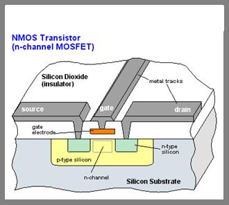
4 Metal-Oxide-Semiconductor (MOS) transistor CMPE12 Winter 2008 J. Ferguson 2-4
5 How big is a transistor? If a CPU die was as big as this whole classroom, a transistor would be CMPE12 Winter 2008 J. Ferguson 2-5
6 Transistors = switches Logically, each transistor is used as a switch Combined to implement logic functions AND, OR, NOT Combined to build higher-level structures Adder, multiplexer, decoder, register, memory Combined to build processor LC-3 CMPE12 Winter 2008 J. Ferguson 2-6
7 Nature of Digital Signals/Information Our world is analog: real number values of energy, mass, time. However a computer signal can only have one of two values: 0 voltage and high voltage. We will call these 0 and 1. This simplification leads to tremendous advantages for computation: detection, self-restoration, etc. CMPE12 Winter 2008 J. Ferguson 2-7
8 Combinational logic is used to create a digital function CMPE12 Winter 2008 J. Ferguson 2-8
9 Basic one and two-input logic gates and functions CMPE12 Winter 2008 J. Ferguson 2-9
10 Use transistors to make combinational logic or Simplification: one output for now CMPE12 Winter 2008 J. Ferguson 2-10
11 Each signal is connected to either a 0 or a 1 1 or Vcc 1 or Vcc Or But never both! 0 or Ground 0 or Ground Transistors make those paths depending the inputs to the gate! CMPE12 Winter 2008 J. Ferguson 2-11
12 n-type MOS transistor n-type MOS (nmos) makes path towards 0 when gate is 1. when Gate has positive voltage, short circuit between #1 and #2 (switch closed) when Gate has zero voltage (0), open circuit between #1 and #2 (switch open) Gate = 1 Gate = 0 CMPE12 Winter 2008 J. Ferguson 2-12
13 p-type MOS transistor p-type is complementary to n-type makes path to 1 when gate is 0 when Gate has positive voltage, open circuit between #1 and #2 (switch open) when Gate has zero voltage, short circuit between #1 and #2 (switch closed) Gate = 1 Gate = 0 CMPE12 Winter 2008 J. Ferguson 2-13
14 CMOS circuit Complementary MOS Uses both n-type and p-type MOS transistors p-type Connects path towards 1 when gate input is 0 n-type Connects path towards 0 when gate input is 1 CMPE12 Winter 2008 J. Ferguson 2-14
15 Inverter (NOT gate) In Out In Out 0 V 2.9 V V 0 V 1 0 Truth Table CMPE12 Winter 2008 J. Ferguson 2-15
16 Truth Table The most basic representation of a logic function. Brute force representation listing the output for all possible input combinations. CMPE12 Winter 2008 J. Ferguson 2-16
17 Truth table Example Inputs A B Outputs X Y 2 #inputs CMPE12 Winter 2008 J. Ferguson 2-17
18 Static CMOS gate rules All potential paths to Vcc (1) must go up through pmos transistors. All potential paths to Gnd (0) must go down through nmos transistors. Implication: all 1s on inputs must put 0 on output and all 0s on inputs must put 1 on output. CMPE12 Winter 2008 J. Ferguson 2-18
19 NAND gate (NOT-AND) Note: Parallel structure on top, serial on bottom. A B C CMPE12 Winter 2008 J. Ferguson 2-19
20 AND gate A B 0 C Add an inverter to a NAND. CMPE12 Winter 2008 J. Ferguson 2-20
21 NOR gate Note: Serial structure on top, parallel on bottom. A B CMPE12 Winter 2008 J. Ferguson C
22 OR gate A B 0 C Add an inverter to a NOR gate. CMPE12 Winter 2008 J. Ferguson 2-22
23 Basic logic gates CMPE12 Winter 2008 J. Ferguson 2-23
24 Axioms of Boolean algebra 0 * 0 = = 1 * 1 = = 0 * 1 = 1 * 0 = = = = = if x = 0 then x = if x = 1 then x = CMPE12 Winter 2008 J. Ferguson 2-24
25 Single-variable theorems x * 0 = x + 1 = x * 1 = x + 0 = x * x = x + x = x * x = x + x = (x ) = CMPE12 Winter 2008 J. Ferguson 2-25
26 Commutative: x* y = x + y = Associative x * (y * z) = x + (y + z) = Distributive x*(y + z ) = x + Y * z = Properties CMPE12 Winter 2008 J. Ferguson 2-26
27 More properties Absorption: x + x * Y = x * (x + y) = Combining: x * Y + x * y = (x + y) * (x + y ) = De Morgan s (x* y) = (x + y) = Other: x + x *y = x * (x + y) = CMPE12 Winter 2008 J. Ferguson 2-27
28 DeMorgan's Law (1/2) (A + B) = A B conversely (AB) = A + B A B A+B A A+B A B AB CMPE12 Winter 2008 J. Ferguson 2-28
29 DeMorgan's Law (2/2) (A + B) = A B conversely (AB) = A + B A B AB A AB A B A+B CMPE12 Winter 2008 J. Ferguson 2-29
30 DeMorgan's Law and SoP Turns AND/OR into NAND/NAND: CMPE12 Winter 2008 J. Ferguson 2-30
31 Product of Sums A second standard way of synthesizing simple circuits. Ex: A B Z CMPE12 Winter 2008 J. Ferguson 2-31
32 DeMorgan's Law and PoS Turns OR/AND into NOR/NOR: CMPE12 Winter 2008 J. Ferguson 2-32
33 DeMorgan's Law: SoP or PoS? Can also generate NOR/NOR circuits, But we prefer NAND/NAND ones. NANDs are faster CMPE12 Winter 2008 J. Ferguson 2-33
34 More than 2 inputs? AND/OR can take any number of inputs. AND = 1 if all inputs are 1. OR = 1 if any input is 1. Similar for NAND/NOR Can implement with multiple two-input gates, or with single CMOS circuit. NAND?? NOR?? CMPE12 Winter 2008 J. Ferguson 2-34
35 CMOS 3-input NAND CMPE12 Winter 2008 J. Ferguson 2-35
36 Example: Logic minimization A B C Y CMPE12 Winter 2008 J. Ferguson 2-36
37 Building functions from logic gates Combinational Logic Circuit output depends only on the current inputs stateless Sequential Logic Circuit output depends on the sequence of inputs (past and present) stores information (state) from past inputs CMPE12 Winter 2008 J. Ferguson 2-37
38 Diversion: Unsigned Integers Represent Positive Integers String of digits: A n-1, A n-2, A 1, A 0 Contribution of A X is A X * base X Values range from 0 to A n 1 Most common bases: 10, 2 CMPE12 Winter 2008 J. Ferguson 2-38
39 n inputs, 2 n outputs Decoder exactly one output is asserted for each possible input pattern 2-to-4 decoder CMPE12 Winter 2008 J. Ferguson 2-39
40 About the little circle It is a logical idea stating that instead of the 1 being true, a 0 is true. When in Boolean logic it can be thought of as an inverter CMPE12 Winter 2008 J. Ferguson 2-40
41 Decoder block A 1 A 0 Sel CMPE12 Winter 2008 J. Ferguson 2-41
42 Abstraction: Decoder Lowest Level (for us): CMOS transistors Highest Level: 2 n Truth Tables or Diagram of previous slide Intermediate Level: Actual Gates making up the decoder CMPE12 Winter 2008 J. Ferguson 2-42
43 Multiplexer 2-way multiplexer: the output is equal to one of the two inputs, based on a selector S A B Z CMPE12 Winter 2008 J. Ferguson 2-43
44 4-way multiplexer n-bit selector and 2 n inputs, one output output equals one of the inputs, depending on selector 4-to-1 MUX CMPE12 Winter 2008 J. Ferguson 2-44
45 Binary addition = = = =... CMPE12 Winter 2008 J. Ferguson 2-45
46 Full Adder Add two bits and carry-in, produce one-bit sum and carry-out. A B 0 0 C in 0 S C out CMPE12 Winter 2008 J. Ferguson 2-46
47 Four-bit Adder CMPE12 Winter 2008 J. Ferguson 2-47
48 Logical completeness Can implement ANY truth table with AND, OR, NOT. A B C D AND combinations that yield a "1" in the truth table. 2. OR the results of the AND gates CMPE12 Winter 2008 J. Ferguson 2-48
49 Recommended exercises on combinational circuits Ex 3.5, 3.6, 3.7, 3.8, 3.9 Ex 3.12, 3.13, 3.14, 3.18 Ex 3.20, 3.22, 3.23, 3.24 with TA/Tut Ex 3.30, 3.31, 3.35 Ex 3.44 CMPE12 Winter 2008 J. Ferguson 2-49
50 Combinational vs. sequential Combinational circuit always gives the same output for a given set of inputs ex: adder always generates sum and carry, regardless of previous inputs CMPE12 Winter 2008 J. Ferguson 2-50
51 Sequential circuit stores information output depends on stored information (state) plus input so a given input might produce different outputs, depending on the stored information example: ticket counter advances when you push the button output depends on previous state useful for building memory elements and state machines CMPE12 Winter 2008 J. Ferguson 2-51
52 An R-S Latch Static Sequential circuits require feedback to hold state. S means set to 1 R means reset to 0 CMPE12 Winter 2008 J. Ferguson 2-52
53 An R-S Latch The input S,R = 0,0 is considered illegal or undefined. S-R latch CMPE12 Winter 2008 J. Ferguson 2-53
54 R-S Latch Summary R = S = 1 hold current value in latch S = 0, R=1 set value to 1 R = 0, S = 1 set value to 0 R = S = 0 both outputs equal one final state determined which input is 0 last, so 00->11 transition is illegal. CMPE12 Winter 2008 J. Ferguson 2-54
55 Not all feedback circuits form latches CMPE12 Winter 2008 J. Ferguson 2-55
56 D-Latch Two inputs: D (data) and WE (write enable) when WE = 1, latch is set to value of D S = NOT(D), R = D when WE = 0, latch holds previous value S = R = 1 the inverter and gate R-S Latch CMPE12 Winter 2008 J. Ferguson 2-56
57 Register A register stores a multi-bit value. We use a collection of D-latches, all controlled by a common WE. When WE=1, n-bit value D is written to register. CMPE12 Winter 2008 J. Ferguson 2-57
58 Memory Now that we know how to store bits, we can build a memory a logical k m array of stored bits. Address Space: number of locations (usually a power of 2) Addressability: number of bits per location (e.g., byte-addressable) k = 2 n locations m bits CMPE12 Winter 2008 J. Ferguson 2-58
59 2 2 x 3 Memory address word select word WE input bits write enable address decoder output bits CMPE12 Winter 2008 J. Ferguson 2-59
60 More about Memory This is a not the way actual memory is implemented. fewer transistors, much more dense, relies on electrical properties But the logical structure is very similar. address decoder word select line word write enable Many kinds of RAM (Random Access Memory) CMPE12 Winter 2008 J. Ferguson 2-60
61 State Machine The basic type of sequential circuit Combines combinational logic with storage Remembers state, and changes output (and state) based on inputs and current state State Machine Inputs Combinational Logic Circuit Outputs Storage Elements CMPE12 Winter 2008 J. Ferguson 2-61
62 Combinational vs. Sequential Two types of combination locks Combinational Success depends only on the values, not the order in which they are set. Sequential Success depends on the sequence of values (e.g, R-13, L-22, R-3). CMPE12 Winter 2008 J. Ferguson 2-62
63 State The state of a system is a snapshot of all the relevant elements of the system at the moment the snapshot is taken. Examples: The state of a basketball game can be represented by the scoreboard. Number of points, time remaining, possession, etc. The state of a tic-tac-toe game can be represented by the placement of X s and O s on the board. CMPE12 Winter 2008 J. Ferguson 2-63
64 State of Sequential Lock Our lock example has four different states, labelled A-D: A: The lock is not open, and no relevant operations have been performed. B: The lock is not open, and the user has completed the R-13 operation. C: The lock is not open, and the user has completed R-13, followed by L-22. D:The lock is open. CMPE12 Winter 2008 J. Ferguson 2-64
65 State Diagram Shows states and actions that cause a transition between states. CMPE12 Winter 2008 J. Ferguson 2-65
66 Finite State Machine A description of a system with the following components: 1. A finite number of states 2. A finite number of external inputs 3. A finite number of external outputs 4. An explicit specification of all state transitions 5. An explicit specification of what determines each external output value Often described by a state diagram. Inputs trigger state transitions. Outputs are associated with each state (or with each transition). CMPE12 Winter 2008 J. Ferguson 2-66
67 The Clock Frequently, a clock circuit triggers transition from one state to the next. 1 0 One Cycle time At the beginning of each clock cycle, state machine makes a transition, based on the current state and the external inputs. Not always required. In lock example, the input itself triggers a transition. CMPE12 Winter 2008 J. Ferguson 2-67
68 Implementing a Finite State Machine Combinational logic Determine outputs and next state. Storage elements Maintain state representation. State Machine Inputs Combinational Logic Circuit Outputs Clock Storage Elements CMPE12 Winter 2008 J. Ferguson 2-68
69 Example of sequential machine A 2-bit counter that counts the number of times that an input is logic 1. When the counter gets to 3, it signals that it is full. State table: how many states? CMPE12 Winter 2008 J. Ferguson 2-69
70 Representing Multi-bit Values Number bits from right (0) to left (n-1) just a convention -- could be left to right, but must be consistent Use brackets to denote range: D[l:r] denotes bit l to bit r, from left to right 15 A = A[14:9] = A[2:0] = 101 May also see A<14:9>, especially in hardware block diagrams. CMPE12 Winter 2008 J. Ferguson 2-70
71 An LC-3 architecture s sneak preview CMPE12 Winter 2008 J. Ferguson 2-71
72 LC-3 Data Path Combinational Logic Storage State Machine CMPE12 Winter 2008 J. Ferguson 2-72
73 Recommended exercises on Sequential Circuits Ex 3.21, 3.34, 3.35 Ex 3.40, 3.41, 3.43 CMPE12 Winter 2008 J. Ferguson 2-73
Introduction to Computer Engineering. CS/ECE 252, Fall 2012 Prof. Guri Sohi Computer Sciences Department University of Wisconsin Madison
 Introduction to Computer Engineering CS/ECE 252, Fall 2012 Prof. Guri Sohi Computer Sciences Department University of Wisconsin Madison Chapter 3 Digital Logic Structures Slides based on set prepared by
CMPE12 - Notes chapter 2. Digital Logic. (Textbook Chapters and 2.1)"
") CMPE12 - Notes chapter 2 Digital Logic (Textbook Chapters 3.1-3.5 and 2.1)" Truth table" The most basic representation of a logic function." Brute force representation listing the output for all possible
CMPE12 - Notes chapter 2 Digital Logic (Textbook Chapters 3.1-3.5 and 2.1)" Truth table" The most basic representation of a logic function." Brute force representation listing the output for all possible
Digital Logic: Boolean Algebra and Gates. Textbook Chapter 3
 Digital Logic: Boolean Algebra and Gates Textbook Chapter 3 Basic Logic Gates XOR CMPE12 Summer 2009 02-2 Truth Table The most basic representation of a logic function Lists the output for all possible
Introduction to Computer Engineering. CS/ECE 252, Spring 2017 Rahul Nayar Computer Sciences Department University of Wisconsin Madison
 Introduction to Computer Engineering CS/ECE 252, Spring 2017 Rahul Nayar Computer Sciences Department University of Wisconsin Madison Chapter 3 Digital Logic Structures Slides based on set prepared by
Digital Logic. CS211 Computer Architecture. l Topics. l Transistors (Design & Types) l Logic Gates. l Combinational Circuits.
 l Logic Gates. l Combinational Circuits.") CS211 Computer Architecture Digital Logic l Topics l Transistors (Design & Types) l Logic Gates l Combinational Circuits l K-Maps Figures & Tables borrowed from:! http://www.allaboutcircuits.com/vol_4/index.html!
CS211 Computer Architecture Digital Logic l Topics l Transistors (Design & Types) l Logic Gates l Combinational Circuits l K-Maps Figures & Tables borrowed from:! http://www.allaboutcircuits.com/vol_4/index.html!
Chapter 3 Digital Logic Structures
 Chapter 3 Digital Logic Structures Original slides from Gregory Byrd, North Carolina State University Modified by C. Wilcox, M. Strout, Y. Malaiya Colorado State University Computing Layers Problems Algorithms
Boolean Algebra and Digital Logic 2009, University of Colombo School of Computing
 IT 204 Section 3.0 Boolean Algebra and Digital Logic Boolean Algebra 2 Logic Equations to Truth Tables X = A. B + A. B + AB A B X 0 0 0 0 3 Sum of Products The OR operation performed on the products of
Lecture 22 Chapters 3 Logic Circuits Part 1
 Lecture 22 Chapters 3 Logic Circuits Part 1 LC-3 Data Path Revisited How are the components Seen here implemented? 5-2 Computing Layers Problems Algorithms Language Instruction Set Architecture Microarchitecture
Floating Point Representation and Digital Logic. Lecture 11 CS301
 Floating Point Representation and Digital Logic Lecture 11 CS301 Administrative Daily Review of today s lecture w Due tomorrow (10/4) at 8am Lab #3 due Friday (9/7) 1:29pm HW #5 assigned w Due Monday 10/8
EE40 Lec 15. Logic Synthesis and Sequential Logic Circuits
 EE40 Lec 15 Logic Synthesis and Sequential Logic Circuits Prof. Nathan Cheung 10/20/2009 Reading: Hambley Chapters 7.4-7.6 Karnaugh Maps: Read following before reading textbook http://www.facstaff.bucknell.edu/mastascu/elessonshtml/logic/logic3.html
LOGIC CIRCUITS. Basic Experiment and Design of Electronics. Ho Kyung Kim, Ph.D.
 Basic Experiment and Design of Electronics LOGIC CIRCUITS Ho Kyung Kim, Ph.D. hokyung@pusan.ac.kr School of Mechanical Engineering Pusan National University Digital IC packages TTL (transistor-transistor
Organisasi dan Arsitektur Komputer L#1: Fundamental Concepts Amil A. Ilham
 Organisasi dan Arsitektur Komputer http://www.unhas.ac.id/amil/stmik2016/arsikom/ L#1: Fundamental Concepts Amil A. Ilham http://www.unhas.ac.id/amil Administrasi Kuliah ADMINISTRASI KULIAH 2 Penilaian
Combinational vs. Sequential. Summary of Combinational Logic. Combinational device/circuit: any circuit built using the basic gates Expressed as
 Summary of Combinational Logic : Computer Architecture I Instructor: Prof. Bhagi Narahari Dept. of Computer Science Course URL: www.seas.gwu.edu/~bhagiweb/cs3/ Combinational device/circuit: any circuit
Number System. Decimal to binary Binary to Decimal Binary to octal Binary to hexadecimal Hexadecimal to binary Octal to binary
 Number System Decimal to binary Binary to Decimal Binary to octal Binary to hexadecimal Hexadecimal to binary Octal to binary BOOLEAN ALGEBRA BOOLEAN LOGIC OPERATIONS Logical AND Logical OR Logical COMPLEMENTATION
Switches: basic element of physical implementations
 Combinational logic Switches Basic logic and truth tables Logic functions Boolean algebra Proofs by re-writing and by perfect induction Winter 200 CSE370 - II - Boolean Algebra Switches: basic element
CHAPTER1: Digital Logic Circuits Combination Circuits
 CS224: Computer Organization S.KHABET CHAPTER1: Digital Logic Circuits Combination Circuits 1 PRIMITIVE LOGIC GATES Each of our basic operations can be implemented in hardware using a primitive logic gate.
CS 226: Digital Logic Design
 CS 226: Digital Logic Design 0 1 1 I S 0 1 0 S Department of Computer Science and Engineering, Indian Institute of Technology Bombay. 1 of 29 Objectives In this lecture we will introduce: 1. Logic functions
ELCT201: DIGITAL LOGIC DESIGN
 ELCT201: DIGITAL LOGIC DESIGN Dr. Eng. Haitham Omran, haitham.omran@guc.edu.eg Dr. Eng. Wassim Alexan, wassim.joseph@guc.edu.eg Lecture 6 Following the slides of Dr. Ahmed H. Madian محرم 1439 ه Winter
UNIVERSITY OF WISCONSIN MADISON
 CS/ECE 252: INTRODUCTION TO COMPUTER ENGINEERING UNIVERSITY OF WISCONSIN MADISON Prof. Gurindar Sohi TAs: Minsub Shin, Lisa Ossian, Sujith Surendran Midterm Examination 2 In Class (50 minutes) Friday,
Combinational Logic. Review of Combinational Logic 1
 Combinational Logic! Switches -> Boolean algebra! Representation of Boolean functions! Logic circuit elements - logic gates! Regular logic structures! Timing behavior of combinational logic! HDLs and combinational
UNIVERSITY OF BOLTON SCHOOL OF ENGINEERING BENG (HONS) ELECTRICAL & ELECTRONICS ENGINEERING EXAMINATION SEMESTER /2017
 ELECTRICAL & ELECTRONICS ENGINEERING EXAMINATION SEMESTER /2017") UNIVERSITY OF BOLTON TW35 SCHOOL OF ENGINEERING BENG (HONS) ELECTRICAL & ELECTRONICS ENGINEERING EXAMINATION SEMESTER 2-2016/2017 INTERMEDIATE DIGITAL ELECTRONICS AND COMMUNICATIONS MODULE NO: EEE5002
UNIVERSITY OF BOLTON TW35 SCHOOL OF ENGINEERING BENG (HONS) ELECTRICAL & ELECTRONICS ENGINEERING EXAMINATION SEMESTER 2-2016/2017 INTERMEDIATE DIGITAL ELECTRONICS AND COMMUNICATIONS MODULE NO: EEE5002
Digital Logic Appendix A
 Digital Logic Appendix A Boolean Algebra Gates Combinatorial Circuits Sequential Circuits 1 Boolean Algebra George Boole ideas 1854 Claude Shannon, apply to circuit design, 1938 Describe digital circuitry
DIGITAL LOGIC CIRCUITS
 DIGITAL LOGIC CIRCUITS Introduction Logic Gates Boolean Algebra Map Specification Combinational Circuits Flip-Flops Sequential Circuits Memory Components Integrated Circuits Digital Computers 2 LOGIC GATES
UNIVERSITI TENAGA NASIONAL. College of Information Technology
 UNIVERSITI TENAGA NASIONAL College of Information Technology BACHELOR OF COMPUTER SCIENCE (HONS.) FINAL EXAMINATION SEMESTER 2 2012/2013 DIGITAL SYSTEMS DESIGN (CSNB163) January 2013 Time allowed: 3 hours
Digital Electronics I
 References Digital Electronics I Katz, R.H. (2004). Contemporary logic design. Benjamin/Cummings. Hayes, J.P. (1993). Introduction to digital logic design. Addison-Wesley. Horowitz, P. & Hill, W. (1989).
Fundamentals of Digital Design
 Fundamentals of Digital Design Digital Radiation Measurement and Spectroscopy NE/RHP 537 1 Binary Number System The binary numeral system, or base-2 number system, is a numeral system that represents numeric
Intro To Digital Logic
 Intro To Digital Logic 1 Announcements... Project 2.2 out But delayed till after the midterm Midterm in a week Covers up to last lecture + next week's homework & lab Nick goes "H-Bomb of Justice" About
Chapter 7. Sequential Circuits Registers, Counters, RAM
 Chapter 7. Sequential Circuits Registers, Counters, RAM Register - a group of binary storage elements suitable for holding binary info A group of FFs constitutes a register Commonly used as temporary storage
Latches. October 13, 2003 Latches 1
 Latches The second part of CS231 focuses on sequential circuits, where we add memory to the hardware that we ve already seen. Our schedule will be very similar to before: We first show how primitive memory
Boolean Algebra. Digital Logic Appendix A. Postulates, Identities in Boolean Algebra How can I manipulate expressions?
 Digital Logic Appendix A Gates Combinatorial Circuits Sequential Circuits Other operations NAND A NAND B = NOT ( A ANDB) = AB NOR A NOR B = NOT ( A ORB) = A + B Truth tables What is the result of the operation
Appendix B. Review of Digital Logic. Baback Izadi Division of Engineering Programs
 Appendix B Review of Digital Logic Baback Izadi Division of Engineering Programs bai@engr.newpaltz.edu Elect. & Comp. Eng. 2 DeMorgan Symbols NAND (A.B) = A +B NOR (A+B) = A.B AND A.B = A.B = (A +B ) OR
LOGIC CIRCUITS. Basic Experiment and Design of Electronics
 Basic Experiment and Design of Electronics LOGIC CIRCUITS Ho Kyung Kim, Ph.D. hokyung@pusan.ac.kr School of Mechanical Engineering Pusan National University Outline Combinational logic circuits Output
SAU1A FUNDAMENTALS OF DIGITAL COMPUTERS
 SAU1A FUNDAMENTALS OF DIGITAL COMPUTERS Unit : I - V Unit : I Overview Fundamentals of Computers Characteristics of Computers Computer Language Operating Systems Generation of Computers 2 Definition of
ECE 250 / CPS 250 Computer Architecture. Basics of Logic Design Boolean Algebra, Logic Gates
 ECE 250 / CPS 250 Computer Architecture Basics of Logic Design Boolean Algebra, Logic Gates Benjamin Lee Slides based on those from Andrew Hilton (Duke), Alvy Lebeck (Duke) Benjamin Lee (Duke), and Amir
211: Computer Architecture Summer 2016
 211: Computer Architecture Summer 2016 Liu Liu Topic: Storage Project3 Digital Logic - Storage: Recap - Review: cache hit rate - Project3 - Digital Logic: - truth table => SOP - simplification: Boolean
ECE/CS 250 Computer Architecture
 ECE/CS 250 Computer Architecture Basics of Logic Design: Boolean Algebra, Logic Gates (Combinational Logic) Tyler Bletsch Duke University Slides are derived from work by Daniel J. Sorin (Duke), Alvy Lebeck
Chapter 2 Boolean Algebra and Logic Gates
 Chapter 2 Boolean Algebra and Logic Gates The most common postulates used to formulate various algebraic structures are: 1. Closure. N={1,2,3,4 }, for any a,b N we obtain a unique c N by the operation
Sequential Logic Circuits
 Chapter 4 Sequential Logic Circuits 4 1 The defining characteristic of a combinational circuit is that its output depends only on the current inputs applied to the circuit. The output of a sequential circuit,
Adders, subtractors comparators, multipliers and other ALU elements
 CSE4: Components and Design Techniques for Digital Systems Adders, subtractors comparators, multipliers and other ALU elements Instructor: Mohsen Imani UC San Diego Slides from: Prof.Tajana Simunic Rosing
ECE 545 Digital System Design with VHDL Lecture 1. Digital Logic Refresher Part A Combinational Logic Building Blocks
 ECE 545 Digital System Design with VHDL Lecture Digital Logic Refresher Part A Combinational Logic Building Blocks Lecture Roadmap Combinational Logic Basic Logic Review Basic Gates De Morgan s Law Combinational
Boolean Algebra. Digital Logic Appendix A. Boolean Algebra Other operations. Boolean Algebra. Postulates, Identities in Boolean Algebra
 Digital Logic Appendix A Gates Combinatorial Circuits Sequential Circuits George Boole ideas 1854 Claude Shannon, apply to circuit design, 1938 (piirisuunnittelu) Describe digital circuitry function programming
Sample Test Paper - I
 Scheme G Sample Test Paper - I Course Name : Computer Engineering Group Marks : 25 Hours: 1 Hrs. Q.1) Attempt any THREE: 09 Marks a) Define i) Propagation delay ii) Fan-in iii) Fan-out b) Convert the following:
Fundamentals of Boolean Algebra
 UNIT-II 1 Fundamentals of Boolean Algebra Basic Postulates Postulate 1 (Definition): A Boolean algebra is a closed algebraic system containing a set K of two or more elements and the two operators and
CS/COE0447: Computer Organization
 CS/COE0447: Computer Organization and Assembly Language Logic Design Review Sangyeun Cho Dept. of Computer Science Logic design? Digital hardware is implemented by way of logic design Digital circuits
Unit II Chapter 4:- Digital Logic Contents 4.1 Introduction... 4
 Unit II Chapter 4:- Digital Logic Contents 4.1 Introduction... 4 4.1.1 Signal... 4 4.1.2 Comparison of Analog and Digital Signal... 7 4.2 Number Systems... 7 4.2.1 Decimal Number System... 7 4.2.2 Binary
Adders, subtractors comparators, multipliers and other ALU elements
 CSE4: Components and Design Techniques for Digital Systems Adders, subtractors comparators, multipliers and other ALU elements Adders 2 Circuit Delay Transistors have instrinsic resistance and capacitance
Lecture 7: Logic design. Combinational logic circuits
 /24/28 Lecture 7: Logic design Binary digital circuits: Two voltage levels: and (ground and supply voltage) Built from transistors used as on/off switches Analog circuits not very suitable for generic
ELEN Electronique numérique
 ELEN0040 - Electronique numérique Patricia ROUSSEAUX Année académique 2014-2015 CHAPITRE 3 Combinational Logic Circuits ELEN0040 3-4 1 Combinational Functional Blocks 1.1 Rudimentary Functions 1.2 Functions
CSC9R6 Computer Design. Practical Digital Logic
 CSC9R6 Computer Design Practical Digital Logic 1 References (for this part of CSC9R6) Hamacher et al: Computer Organization App A. In library Floyd: Digital Fundamentals Ch 1, 3-6, 8-10 web page: www.prenhall.com/floyd/
CS/COE1541: Introduction to Computer Architecture. Logic Design Review. Sangyeun Cho. Computer Science Department University of Pittsburgh
 CS/COE54: Introduction to Computer Architecture Logic Design Review Sangyeun Cho Computer Science Department Logic design? Digital hardware is implemented by way of logic design Digital circuits process
 vidyarthiplus.com vidyarthiplus.com vidyarthiplus.com ANNA UNIVERSITY- COMBATORE B.E./ B.TECH. DEGREE EXAMINATION - JUNE 2009. ELECTRICAL & ELECTONICS ENGG. - FOURTH SEMESTER DIGITAL LOGIC CIRCUITS PART-A
Dept. of ECE, CIT, Gubbi Page 1
 Verification: 1) A.B = A + B 7404 7404 7404 A B A.B A.B 0 0 0 1 0 1 0 1 1 0 0 1 1 1 1 0 A B A B A + B 0 0 1 1 1 0 1 1 0 1 1 0 0 1 1 1 1 0 0 0 2) A+B = A. B 7404 7404 7404 A B A+B A+B 0 0 0 1 0 1 1 0 1
CSE370: Introduction to Digital Design
 CSE370: Introduction to Digital Design Course staff Gaetano Borriello, Brian DeRenzi, Firat Kiyak Course web www.cs.washington.edu/370/ Make sure to subscribe to class mailing list (cse370@cs) Course text
Dynamic Combinational Circuits. Dynamic Logic
 Dynamic Combinational Circuits Dynamic circuits Charge sharing, charge redistribution Domino logic np-cmos (zipper CMOS) Krish Chakrabarty 1 Dynamic Logic Dynamic gates use a clocked pmos pullup Two modes:
Chapter 4. Sequential Logic Circuits
 Chapter 4 Sequential Logic Circuits 1 2 Chapter 4 4 1 The defining characteristic of a combinational circuit is that its output depends only on the current inputs applied to the circuit. The output of
ECE 545 Digital System Design with VHDL Lecture 1A. Digital Logic Refresher Part A Combinational Logic Building Blocks
 ECE 545 Digital System Design with VHDL Lecture A Digital Logic Refresher Part A Combinational Logic Building Blocks Lecture Roadmap Combinational Logic Basic Logic Review Basic Gates De Morgan s Laws
ECE/CS 250: Computer Architecture. Basics of Logic Design: Boolean Algebra, Logic Gates. Benjamin Lee
 ECE/CS 250: Computer Architecture Basics of Logic Design: Boolean Algebra, Logic Gates Benjamin Lee Slides based on those from Alvin Lebeck, Daniel Sorin, Andrew Hilton, Amir Roth, Gershon Kedem Admin
CS/COE0447: Computer Organization
 Logic design? CS/COE0447: Computer Organization and Assembly Language Logic Design Review Digital hardware is implemented by way of logic design Digital circuits process and produce two discrete values:
Appendix A: Digital Logic. Principles of Computer Architecture. Principles of Computer Architecture by M. Murdocca and V. Heuring
 - Principles of Computer rchitecture Miles Murdocca and Vincent Heuring 999 M. Murdocca and V. Heuring -2 Chapter Contents. Introduction.2 Combinational Logic.3 Truth Tables.4 Logic Gates.5 Properties
Static CMOS Circuits. Example 1
 Static CMOS Circuits Conventional (ratio-less) static CMOS Covered so far Ratio-ed logic (depletion load, pseudo nmos) Pass transistor logic ECE 261 Krish Chakrabarty 1 Example 1 module mux(input s, d0,
COSC 243. Introduction to Logic And Combinatorial Logic. Lecture 4 - Introduction to Logic and Combinatorial Logic. COSC 243 (Computer Architecture)
") COSC 243 Introduction to Logic And Combinatorial Logic 1 Overview This Lecture Introduction to Digital Logic Gates Boolean algebra Combinatorial Logic Source: Chapter 11 (10 th edition) Source: J.R. Gregg,
COSC 243 Introduction to Logic And Combinatorial Logic 1 Overview This Lecture Introduction to Digital Logic Gates Boolean algebra Combinatorial Logic Source: Chapter 11 (10 th edition) Source: J.R. Gregg,
CS470: Computer Architecture. AMD Quad Core
 CS470: Computer Architecture Yashwant K. Malaiya, Professor malaiya@cs.colostate.edu AMD Quad Core 1 Architecture Layers Building blocks Gates, flip-flops Functional bocks: Combinational, Sequential Instruction
Written reexam with solutions for IE1204/5 Digital Design Monday 14/
 Written reexam with solutions for IE204/5 Digital Design Monday 4/3 206 4.-8. General Information Examiner: Ingo Sander. Teacher: William Sandqvist phone 08-7904487 Exam text does not have to be returned
CSE140: Components and Design Techniques for Digital Systems. Midterm Information. Instructor: Mohsen Imani. Sources: TSR, Katz, Boriello & Vahid
 CSE140: Components and Design Techniques for Digital Systems Midterm Information Instructor: Mohsen Imani Midterm Topics In general: everything that was covered in homework 1 and 2 and related lectures,
EC-121 Digital Logic Design
 EC-121 Digital Logic Design Lecture 2 [Updated on 02-04-18] Boolean Algebra and Logic Gates Dr Hashim Ali Spring 2018 Department of Computer Science and Engineering HITEC University Taxila!1 Overview What
CHW 261: Logic Design
 CHW 26: Logic Design Instructors: Prof. Hala Zayed Dr. Ahmed Shalaby http://www.bu.edu.eg/staff/halazayed4 http://bu.edu.eg/staff/ahmedshalaby4# Slide Digital Fundamentals Digital Concepts Slide 2 What?
Combinational Logic Trainer Lab Manual
 Combinational Logic Trainer Lab Manual Control Inputs Microprocessor Data Inputs ff Control Unit '0' Datapath MUX Nextstate Logic State Memory Register Output Logic Control Signals ALU ff Register Status
EECS 270 Midterm 2 Exam Answer Key Winter 2017
 EES 270 Midterm 2 Exam nswer Key Winter 2017 Name: unique name: Sign the honor code: I have neither given nor received aid on this exam nor observed anyone else doing so. NOTES: 1. This part of the exam
ECE321 Electronics I
 ECE321 Electronics I Lecture 1: Introduction to Digital Electronics Payman Zarkesh-Ha Office: ECE Bldg. 230B Office hours: Tuesday 2:00-3:00PM or by appointment E-mail: payman@ece.unm.edu Slide: 1 Textbook
E40M. Binary Numbers. M. Horowitz, J. Plummer, R. Howe 1
 E40M Binary Numbers M. Horowitz, J. Plummer, R. Howe 1 Reading Chapter 5 in the reader A&L 5.6 M. Horowitz, J. Plummer, R. Howe 2 Useless Box Lab Project #2 Adding a computer to the Useless Box alows us
Vidyalankar S.E. Sem. III [CMPN] Digital Logic Design and Analysis Prelim Question Paper Solution
![Vidyalankar S.E. Sem. III [CMPN] Digital Logic Design and Analysis Prelim Question Paper Solution](/thumbs/90/103673562.jpg "Vidyalankar S.E. Sem. III [CMPN] Digital Logic Design and Analysis Prelim Question Paper Solution") . (a) (i) ( B C 5) H (A 2 B D) H S.E. Sem. III [CMPN] Digital Logic Design and Analysis Prelim Question Paper Solution ( B C 5) H (A 2 B D) H = (FFFF 698) H (ii) (2.3) 4 + (22.3) 4 2 2. 3 2. 3 2 3. 2 (2.3)
. (a) (i) ( B C 5) H (A 2 B D) H S.E. Sem. III [CMPN] Digital Logic Design and Analysis Prelim Question Paper Solution ( B C 5) H (A 2 B D) H = (FFFF 698) H (ii) (2.3) 4 + (22.3) 4 2 2. 3 2. 3 2 3. 2 (2.3)
University of Toronto Faculty of Applied Science and Engineering Edward S. Rogers Sr. Department of Electrical and Computer Engineering
 University of Toronto Faculty of Applied Science and Engineering Edward S. Rogers Sr. Department of Electrical and Computer Engineering Final Examination ECE 241F - Digital Systems Examiners: J. Rose and
CHAPTER 7. Exercises 17/ / /2 2 0
 CHAPTER 7 Exercises E7. (a) For the whole part, we have: Quotient Remainders 23/2 /2 5 5/2 2 2/2 0 /2 0 Reading the remainders in reverse order, we obtain: 23 0 = 0 2 For the fractional part we have 2
Reg. No. Question Paper Code : B.E./B.Tech. DEGREE EXAMINATION, NOVEMBER/DECEMBER Second Semester. Computer Science and Engineering
 Sp 6 Reg. No. Question Paper Code : 27156 B.E./B.Tech. DEGREE EXAMINATION, NOVEMBER/DECEMBER 2015. Second Semester Computer Science and Engineering CS 6201 DIGITAL PRINCIPLES AND SYSTEM DESIGN (Common
ELEC Digital Logic Circuits Fall 2014 Sequential Circuits (Chapter 6) Finite State Machines (Ch. 7-10)
 Finite State Machines (Ch. 7-10)") ELEC 2200-002 Digital Logic Circuits Fall 2014 Sequential Circuits (Chapter 6) Finite State Machines (Ch. 7-10) Vishwani D. Agrawal James J. Danaher Professor Department of Electrical and Computer Engineering
ELEC 2200-002 Digital Logic Circuits Fall 2014 Sequential Circuits (Chapter 6) Finite State Machines (Ch. 7-10) Vishwani D. Agrawal James J. Danaher Professor Department of Electrical and Computer Engineering
2009 Spring CS211 Digital Systems & Lab CHAPTER 2: INTRODUCTION TO LOGIC CIRCUITS
 CHAPTER 2: INTRODUCTION TO LOGIC CIRCUITS What will we learn? 2 Logic functions and circuits Boolean Algebra Logic gates and Synthesis CAD tools and VHDL Read Section 2.9 and 2.0 Terminology 3 Digital
Lecture A: Logic Design and Gates
 Lecture A: Logic Design and Gates Syllabus My office hours 9.15-10.35am T,Th or gchoi@ece.tamu.edu 333G WERC Text: Brown and Vranesic Fundamentals of Digital Logic,» Buy it.. Or borrow it» Other book:
Topics. Dynamic CMOS Sequential Design Memory and Control. John A. Chandy Dept. of Electrical and Computer Engineering University of Connecticut
 Topics Dynamic CMOS Sequential Design Memory and Control Dynamic CMOS In static circuits at every point in time (except when switching) the output is connected to either GND or V DD via a low resistance
Digital Circuits. 1. Inputs & Outputs are quantized at two levels. 2. Binary arithmetic, only digits are 0 & 1. Position indicates power of 2.
 Digital Circuits 1. Inputs & Outputs are quantized at two levels. 2. inary arithmetic, only digits are 0 & 1. Position indicates power of 2. 11001 = 2 4 + 2 3 + 0 + 0 +2 0 16 + 8 + 0 + 0 + 1 = 25 Digital
ELCT201: DIGITAL LOGIC DESIGN
 ELCT2: DIGITAL LOGIC DESIGN Dr. Eng. Haitham Omran, haitham.omran@guc.edu.eg Dr. Eng. Wassim Alexan, wassim.joseph@guc.edu.eg Lecture 2 Following the slides of Dr. Ahmed H. Madian ذو الحجة 438 ه Winter
2.1. Unit 2. Digital Circuits (Logic)
") 2.1 Unit 2 Digital Circuits (Logic) 2.2 Moving from voltages to 1's and 0's ANALOG VS. DIGITAL volts volts 2.3 Analog signal Signal Types Continuous time signal where each voltage level has a unique meaning
2.1 Unit 2 Digital Circuits (Logic) 2.2 Moving from voltages to 1's and 0's ANALOG VS. DIGITAL volts volts 2.3 Analog signal Signal Types Continuous time signal where each voltage level has a unique meaning
KUMARAGURU COLLEGE OF TECHNOLOGY COIMBATORE
 Estd-1984 KUMARAGURU COLLEGE OF TECHNOLOGY COIMBATORE 641 006 QUESTION BANK UNIT I PART A ISO 9001:2000 Certified 1. Convert (100001110.010) 2 to a decimal number. 2. Find the canonical SOP for the function
Digital electronics form a class of circuitry where the ability of the electronics to process data is the primary focus.
 Chapter 2 Digital Electronics Objectives 1. Understand the operation of basic digital electronic devices. 2. Understand how to describe circuits which can process digital data. 3. Understand how to design
Synchronous Sequential Logic
 1 IT 201 DIGITAL SYSTEMS DESIGN MODULE4 NOTES Synchronous Sequential Logic Sequential Circuits - A sequential circuit consists of a combinational circuit and a feedback through the storage elements in
Lecture 3 Review on Digital Logic (Part 2)
") Lecture 3 Review on Digital Logic (Part 2) Xuan Silvia Zhang Washington University in St. Louis http://classes.engineering.wustl.edu/ese461/ ircuit Optimization Simplest implementation ost criterion literal
Lecture 3 Review on Digital Logic (Part 2) Xuan Silvia Zhang Washington University in St. Louis http://classes.engineering.wustl.edu/ese461/ ircuit Optimization Simplest implementation ost criterion literal
CPE100: Digital Logic Design I
 Professor Brendan Morris, SEB 3216, brendan.morris@unlv.edu CPE100: Digital Logic Design I Midterm01 Review http://www.ee.unlv.edu/~b1morris/cpe100/ 2 Logistics Thursday Oct. 5 th In normal lecture (13:00-14:15)
EE 209 Logic Cumulative Exam Name:
 EE 209 Logic Cumulative Exam Name: 1.) Answer the following questions as True or False a.) A 4-to-1 multiplexer requires at least 4 select lines: true / false b.) An 8-to-1 mux and no other logi can be
Midterm Examination # 1 Wednesday, February 25, Duration of examination: 75 minutes
 Page 1 of 10 School of Computer Science 60-265-01 Computer Architecture and Digital Design Winter 2009 Semester Midterm Examination # 1 Wednesday, February 25, 2009 Student Name: First Name Family Name
Introduction to CMOS VLSI Design Lecture 1: Introduction
 Introduction to CMOS VLSI Design Lecture 1: Introduction David Harris, Harvey Mudd College Kartik Mohanram and Steven Levitan University of Pittsburgh Introduction Integrated circuits: many transistors
DIGITAL LOGIC CIRCUITS
 DIGITAL LOGIC CIRCUITS Introduction Logic Gates Boolean Algebra Map Specification Combinational Circuits Flip-Flops Sequential Circuits Memor Components Integrated Circuits BASIC LOGIC BLOCK - GATE - Logic
The Design Procedure. Output Equation Determination - Derive output equations from the state table
 The Design Procedure Specification Formulation - Obtain a state diagram or state table State Assignment - Assign binary codes to the states Flip-Flop Input Equation Determination - Select flipflop types
University of Toronto Faculty of Applied Science and Engineering Final Examination
 University of Toronto Faculty of Applied Science and Engineering Final Examination ECE 24S - Digital Systems Examiner: Belinda Wang, Jianwen Zhu 2: - 4:3pm, April 26th, 24 Duration: 5 minutes (2.5 hours)
Philadelphia University Student Name: Student Number:
 Philadelphia University Student Name: Student Number: Faculty of Engineering Serial Number: Final Exam, First Semester: 2017/2018 Dept. of Computer Engineering Course Title: Logic Circuits Date: 29/01/2018
Chapter 2 Combinational Logic Circuits
 Logic and Computer Design Fundamentals Chapter 2 Combinational Logic Circuits Part 3 Additional Gates and Circuits Charles Kime & Thomas Kaminski 2008 Pearson Education, Inc. (Hyperlinks are active in
Logic design? Transistor as a switch. Layered design approach. CS/COE1541: Introduction to Computer Architecture. Logic Design Review.
 Logic design? CS/COE54: Introduction to Computer rchitecture Digital hardware is implemented by way of logic design Digital circuits process and produce two discrete values: and Example: -bit full adder
Lecture 10: Synchronous Sequential Circuits Design
 Lecture 0: Synchronous Sequential Circuits Design. General Form Input Combinational Flip-flops Combinational Output Circuit Circuit Clock.. Moore type has outputs dependent only on the state, e.g. ripple
Memory, Latches, & Registers
 Memory, Latches, & Registers 1) Structured Logic Arrays 2) Memory Arrays 3) Transparent Latches 4) How to save a few bucks at toll booths 5) Edge-triggered Registers L13 Memory 1 General Table Lookup Synthesis
SIR C.R.REDDY COLLEGE OF ENGINEERING ELURU DIGITAL INTEGRATED CIRCUITS (DIC) LABORATORY MANUAL III / IV B.E. (ECE) : I - SEMESTER
 LABORATORY MANUAL III / IV B.E. (ECE) : I - SEMESTER") SIR C.R.REDDY COLLEGE OF ENGINEERING ELURU 534 007 DIGITAL INTEGRATED CIRCUITS (DIC) LABORATORY MANUAL III / IV B.E. (ECE) : I - SEMESTER DEPARTMENT OF ELECTRONICS AND COMMUNICATION ENGINEERING DIGITAL
SIR C.R.REDDY COLLEGE OF ENGINEERING ELURU 534 007 DIGITAL INTEGRATED CIRCUITS (DIC) LABORATORY MANUAL III / IV B.E. (ECE) : I - SEMESTER DEPARTMENT OF ELECTRONICS AND COMMUNICATION ENGINEERING DIGITAL
Section 3: Combinational Logic Design. Department of Electrical Engineering, University of Waterloo. Combinational Logic
 Section 3: Combinational Logic Design Major Topics Design Procedure Multilevel circuits Design with XOR gates Adders and Subtractors Binary parallel adder Decoders Encoders Multiplexers Programmed Logic