INF5490 RF MEMS. LN03: Modeling, design and analysis. Spring 2008, Oddvar Søråsen Department of Informatics, UoO
|
|
|
- Allen Robertson
- 5 years ago
- Views:
Transcription
1 INF5490 RF MEMS LN03: Modeling, design and analysis Spring 2008, Oddvar Søråsen Department of Informatics, UoO 1
2 Today s lecture MEMS functional operation Transducer principles Sensor principles Methods for RF MEMS modeling 1. Simple mathematical models 2. Converting to electrical equivalents (3. Analyzing using Finite Element Methods) LN04 2
3 Transducers for (RF) MEMS Electromechanical transducers Transforming electrical energy mechanical energy Transducer principles Electrostatic Electromagnetic Electro thermal Piezoelectric 3
4 Transducer principles Electrostatic transducers Principle: Forces exist between electric charges Coulombs law Stored energy when mechanical or electrical work is performed on the unit can be converted to the other form of energy The most used form of electromechanical energy conversion Fabrication is simple Often implemented using a capacitor with movable plates Vertical movement: parallel plates Horizontal movement: Comb structures 4
5 Electrostatic transducers + Beneficial due to simplicity + Actuation controlled by voltage voltage charge attractive force movement + Movement gives current movement variable capacitor current when voltage is constant: Q = V C and i = dq/dt = V dc/dt Need environmental protection (dust) Packaging required (vacuum) Transduction mechanism is non-linear Gives distortions (force is not proportional to voltage) Solution: small signal variations around a DC voltage 5
6 Transducer principles, contd. Electromagnetic transducers Magnetic windings pull the element Electro thermal actuators Different thermal expansions on different locations due to temperature gradients Large deflections can be obtained Slow 6
7 Transducer principles, contd. Piezoelectric transducers In some anisotropic crystalline materials the charges will be displaced when stressed electric field stress = mechanical stress (Norw: mekanisk spenning) Similarly, strain results when an electric field is applied strain = mechanical strain (Norw: mekanisk tøyning ) Ex. PZT (lead zirconate titanates) ceramic materials (Electrostrictive transducers Mechanical deformation by electric field Magnetostrictive transducers Deformation by magnetic field) 7
8 Comparing different transducer principles 8
9 Sensor principles Piezoresistive detection Capacitive detection Piezoelectric detection Resonance detection 9
10 Sensor principles Piezoresistive detection Resistance varies due to external pressure/stress Used in pressure sensors deflection of membrane Piezoresistors placed on membrane where strain is maximum Resistor value is proportional to strain Performance of piezoresistive micro sensors is temperature dependent 10

11 Pressure sensor Senturia 11
")
12 Sensor principles, contd. Capacitive detection Exploiting capacitance variations Pressure electric signal Detected by change in C: influencing oscillation frequency, charge, voltage (V) Potentially higher performance than piezoresistive detection + Better sensitivity + Can detect small pressure variations + High stability 12
13 Sensor principles, contd. Piezoelectric detection Electric charge distribution changed due to external force electric field current Resonance detection Analogy: stress variation on a string gives strain and is changing the natural resonance frequency 13
14 Methods for modeling RF MEMS 1. Simple mathematical models Ex. parallel plate capacitor 2. Converting to electrical equivalents 3. Analysis using Finite Element Methods 14
15 1. Simple mathematical models Use equations, formulas describing the physical phenomena Simplification, approximations Explicit solutions for simple problems linearization around a bias point Numerical solution of the set of equations Typical differential equations + Gives the designer insight/ understanding How the performance changes by parameter variations May be used for initial estimates 15
16 Ex. On mathematical modeling Important equations for many RF MEMS components: Parallel plate capacitor! Studyelectrostatic actuation of the capacitor with one spring-suspended plate Calculating pull-in Formulas and figures 16
17 Electrostatics + q - q F Electric force between charges: Coulombs law 1 q q F = 4 πε r r Electric field = force pr. unit charge E = Work done by a force = change in potential energy F q 0 W a b b = F a dl = U a U b Potential, V = potential energy pr. unit charge V = U q 0 Voltage = potential difference V a V b b = E dl a 17
18 Capacitance a b E d + Q V ab Definition of capacitance C = Q V ab A -Q Surface charge density = σ σ Q 1 E = = ε A ε 0 0 C = Q V ab = ε 0 A d Voltage V ab = E d = Q A ε 0 d Energy stored in a capacitor, C, that is charged to a voltage V 0 at a current dt i = Q & = C dv U = dv v i dt = v C dt = C dt V0 1 2 ε0 v dv = CV0 = A V d
19 Parallel plate capacitor Attractive force between plates F U = d = d εa ( V 2d 2 ) = εav 2d
20 Movable capacitor plate Assumptions for calculations: Suppose air between plates Spring attached to upper plate Spring constant: k Voltage is turned on Electrostatic attraction At equilibrium Forces up and forces down are in balance 20
21 Force balance k = spring constant d0 = gap at 0V and zero spring strain d = d0 z z=d0 d deflection from start position Force on upper plate at V and d: = 0 at equilibrium 21
22 Two equilibrium positions ς = 1 d/d0 Senturia 22
23 Stability How the forces develop when d decreases Suppose a small perturbation in the gap at constant voltage Suppose the gap decreases If the upward force also deceases, the system is UNSTABLE! 23
24 Stability, contd. Stability condition: Pull-in when: 24
25 Pull-in Pull-in when: 25
26 Pull-in Senturia 26
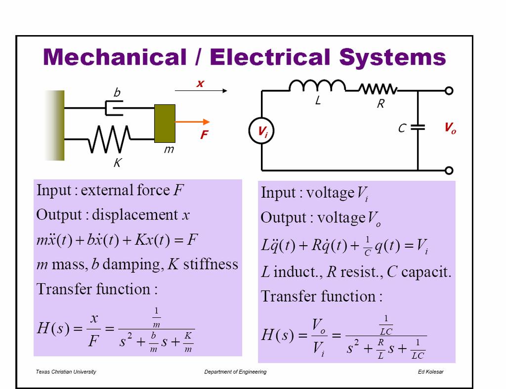
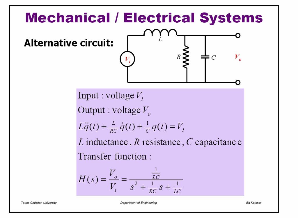
27 2. Converting to electrical equivalents Mechanical behavior can be modeled using electrical circuit elements Mechanical structure simplifications equivalent electrical circuit ex. spring/mass R, C, L Possible to interconnect electrical and mechanical energy domains Simplified modeling and co-simulation of electronic and mechanical parts of the system Proper analysis-tools can be used Ex. SPICE 27
28 Converting to electrical equivalents, contd. We will discuss: Needed circuit theory Conversion principles effort - flow Example of conversion Mechanical resonator In a future lecture: Co-existence and coupling between various energy domains 28
29 Circuit theory Basic circuit elements: R, C, L Current and voltage equations for basic elements (low frequency) Ohms law, C and L-equations V = RI, I = C dv/dt, V = L di/dt Laplace transformation From differential equations to algebraic (s-polynomial) Complex impedances: R, 1/sC, sl Kirchhoffs equations Σ current into nodes = 0, Σ voltage in a loop = 0 29
30 Effort - flow Electrical circuits are described by a set of variables: conjugate power variables Voltage V: across or effort variable Current I: through or flow variable An effort variable drives a flow variable through an impedance, Z Circuit element is modeled as a 1-port with terminals Same current (f = flow) in and out and through the element Positive flow into a terminal defining a positive effort 30
31 Energy-domains, analogies Various energy domains exist Electric, elastic, thermal, for liquids etc. For every energy domain it is possible to define a set of conjugate power variables that may be used as basis for lumped component modeling using equivalent circuits elements Table 5.1 Senturia -> 31
32 Ex. of conjugate power variables 32
33 Conjugate power variables: e,f Assume conversion between energy domains were the energy is conserved! Properties e * f = power e / f = impedance Generalized displacement represents the state, f. ex. position or charge f ( t) = q& ( t) e * q = energy t q( t) = f ( t) dt + q( t0) t 0 33
34 Generalized momentum t p( t) = e( t) dt + p( t ) 0 Mechanics: impulse F*dt= mv mv0 t 0 General: p * f = energy 34
35 Ex.: Mechanical energy domain force velocity position momentum force x time work/time = power force*distance = work = energy energy 35
36 Ex.: Electrical energy domain voltage current charge power energy 36
37 e V - convention Senturia and Tilmans use the e V convention Ex. electrical and mechanical circuits e V (voltage) equivalent to F (force) f I (current) equivalent to v (velocity) q Q(charge) equivalent to x (position) e * f = power injected into the element H. Tilmans, Equivalent circuit representation of electromagnetical transducers: I. Lumped-parameter systems, J. Micromech. Microeng., Vol. 6, pp ,
38 Other conventions Different conventions exist for defining throughor across-variables * alternativt 38
39 Generalized circuit elements One-port circuit elements R, dissipating element C, L, energy-storing elements Elements can have a general function! Can be used in various energy domains 39
40 Generalized capacitance Compare with a simplified case: -a linear capacitor definition of C 40
41 Generalized capacitance, contd. Capacitance is associated with stored potential energy Co-energy: 41
42 Energy stored in parallel plate capacitor Energy: W ( Q) Q Q = e dq = 0 0 q C dq = 2 Q 2C Co-energy: W * ( V ) = V V q de = C v dv = 0 0 CV 2 2 * W ( V ) = W ( Q) for linear capacitance 42
43 Mechanical spring Hook s law: F = k x Stored energy Compare with capacitor 1 1 W ( Q) = Q 2 C 2 Q x1 displacement displacement 1/C equivalent to k 43
44 Compliance Compliance = inverse stiffness 1 C spring = k Stiff spring small capacitor Soft spring large capacitor 44
45 Generalized inductance Energy also defined as: Energy = stored kinetic energy 45
46 Ex.: Electrical inductor Co-energy: 46
47 Analogy between mass (mechanical inertance) and inductance L A mechanical system has linear momentum: p = mv Flow: Co-energy: 47
48 Analogy between m and L Compare with: L is equivalent to m m = L inertance Mechanical inertance = mass m is analog to inductance L 48
49 Interconnecting elements e V follows two basic principles Elements that share a common flow, and hence a common variation of displacement, are connected in series Elements that share a common effort are connected in parallel 49
50 Ex. of interconnection: Direct transformation 50
51 51
52 52
53 53
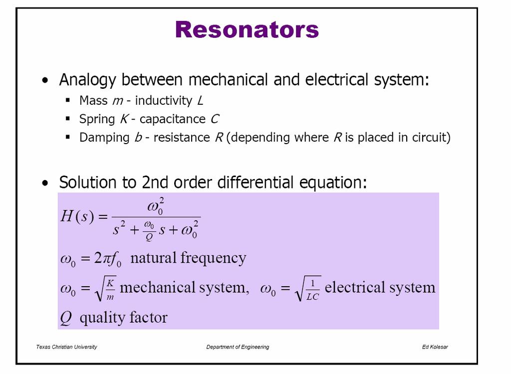
54 System without damping (b=0, R=0) ω 1 ω LC 0 =, 0 = k m 54
55 System without damping, contd. 55
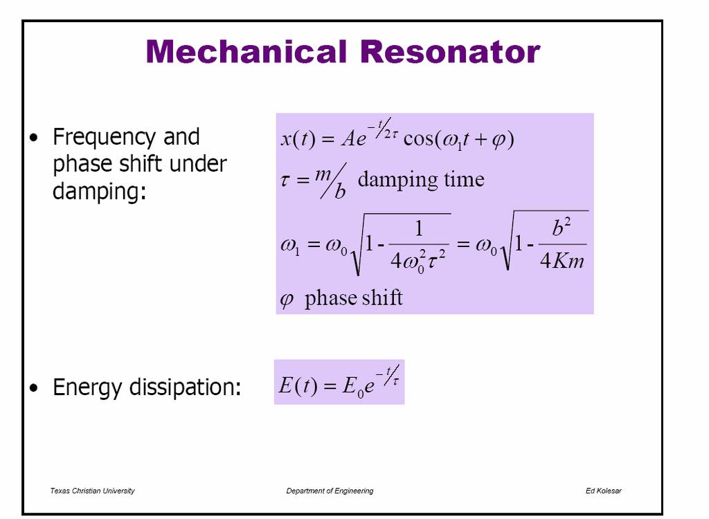
56 With damping 56
57 Damped system, contd. 57
58 58
59 What is the meaning of damping time? Power initial conditions 59
60 Q-factor and damping time General equation mechanical electrical 60
61 Amplitude at resonance for forced vibrations 61
INF5490 RF MEMS. LN06: RF MEMS switches, II. Spring 2012, Oddvar Søråsen Department of Informatics, UoO
 INF5490 RF MEMS LN06: RF MEMS switches, II Spring 2012, Oddvar Søråsen Department of Informatics, UoO 1 Today s lecture Design of RF MEMS switches Electromechanical design, II RF design Examples of implementations
EE C245 ME C218 Introduction to MEMS Design
 EE C245 ME C218 Introduction to MEMS Design Fall 2007 Prof. Clark T.-C. Nguyen Dept. of Electrical Engineering & Computer Sciences University of California at Berkeley Berkeley, CA 94720 Lecture 22: Capacitive
Transduction Based on Changes in the Energy Stored in an Electrical Field
 Lecture 6-1 Transduction Based on Changes in the Energy Stored in an Electrical Field Electric Field and Forces Suppose a charged fixed q 1 in a space, an exploring charge q is moving toward the fixed
Transduction Based on Changes in the Energy Stored in an Electrical Field. Lecture 6-5. Department of Mechanical Engineering
 Transduction Based on Changes in the Energy Stored in an Electrical Field Lecture 6-5 Transducers with cylindrical Geometry For a cylinder of radius r centered inside a shell with with an inner radius
PIEZOELECTRIC TECHNOLOGY PRIMER
 PIEZOELECTRIC TECHNOLOGY PRIMER James R. Phillips Sr. Member of Technical Staff CTS Wireless Components 4800 Alameda Blvd. N.E. Albuquerque, New Mexico 87113 Piezoelectricity The piezoelectric effect is
EE 5344 Introduction to MEMS CHAPTER 6 Mechanical Sensors. 1. Position Displacement x, θ 2. Velocity, speed Kinematic
 I. Mechanical Measurands: 1. Classification of main types: EE 5344 Introduction MEMS CHAPTER 6 Mechanical Sensors 1. Position Displacement x, θ. Velocity, speed Kinematic dx dθ v =, = ω 3. Acceleration
Transduction Based on Changes in the Energy Stored in an Electrical Field
 Lecture 6- Transduction Based on Changes in the Energy Stored in an Electrical Field Actuator Examples Microgrippers Normal force driving In-plane force driving» Comb-drive device F = εav d 1 ε oε F rwv
ECE421: Electronics for Instrumentation MEP382: Design of Applied Measurement Systems Lecture #2: Transduction Mechanisms
 ECE421: Electronics for Instrumentation MEP382: Design of Applied Measurement Systems Lecture #2: Transduction Mechanisms Mostafa Soliman, Ph.D. April 28 th 2014 Slides are borrowed from Dr. Moahmed Elshiekh
Inductance, RL and RLC Circuits
 Inductance, RL and RLC Circuits Inductance Temporarily storage of energy by the magnetic field When the switch is closed, the current does not immediately reach its maximum value. Faraday s law of electromagnetic
PES 1120 Spring 2014, Spendier Lecture 35/Page 1
 PES 0 Spring 04, Spendier Lecture 35/Page Today: chapter 3 - LC circuits We have explored the basic physics of electric and magnetic fields and how energy can be stored in capacitors and inductors. We
EE C245 / ME C218 INTRODUCTION TO MEMS DESIGN FALL 2011 C. Nguyen PROBLEM SET #7. Table 1: Gyroscope Modeling Parameters
 Issued: Wednesday, Nov. 23, 2011. PROBLEM SET #7 Due (at 7 p.m.): Thursday, Dec. 8, 2011, in the EE C245 HW box in 240 Cory. 1. Gyroscopes are inertial sensors that measure rotation rate, which is an extremely
MCT151: Introduction to Mechatronics Lecture 10: Sensors & Transduction Mechanisms
 Faculty of Engineering MCT151: Introduction to Mechatronics Lecture 10: Sensors & Transduction Mechanisms Slides are borrowed from Dr. Mohamed Elshiekh lectures Types of sensors Sensors are considered
E05 Resonator Design
 POLITECNICO DI MILANO MSC COURSE - MEMS AND MICROSENSORS - 2018/2019 E05 Resonator Design Giorgio Mussi 16/10/2018 In this class we will learn how an in-plane MEMS resonator handles process variabilities,
EE C245 / ME C218 INTRODUCTION TO MEMS DESIGN FALL 2009 PROBLEM SET #7. Due (at 7 p.m.): Thursday, Dec. 10, 2009, in the EE C245 HW box in 240 Cory.
: Thursday, Dec. 10, 2009, in the EE C245 HW box in 240 Cory.") Issued: Thursday, Nov. 24, 2009 PROBLEM SET #7 Due (at 7 p.m.): Thursday, Dec. 10, 2009, in the EE C245 HW box in 240 Cory. 1. Gyroscopes are inertial sensors that measure rotation rate, which is an extremely
Issued: Thursday, Nov. 24, 2009 PROBLEM SET #7 Due (at 7 p.m.): Thursday, Dec. 10, 2009, in the EE C245 HW box in 240 Cory. 1. Gyroscopes are inertial sensors that measure rotation rate, which is an extremely
AP Physics C Mechanics Objectives
 AP Physics C Mechanics Objectives I. KINEMATICS A. Motion in One Dimension 1. The relationships among position, velocity and acceleration a. Given a graph of position vs. time, identify or sketch a graph
Lumped Modeling in Thermal Domain
 EEL55: Principles of MEMS ransducers (Fall 003) Instructor: Dr. Hui-Kai Xie Lumped Modeling in hermal Domain Last lecture oday: Lumped modeling Self-heating resistor Self-heating resistor Other dissipation
ET3-7: Modelling II(V) Electrical, Mechanical and Thermal Systems
 Electrical, Mechanical and Thermal Systems") ET3-7: Modelling II(V) Electrical, Mechanical and Thermal Systems Agenda of the Day 1. Resume of lesson I 2. Basic system models. 3. Models of basic electrical system elements 4. Application of Matlab/Simulink
ET3-7: Modelling II(V) Electrical, Mechanical and Thermal Systems Agenda of the Day 1. Resume of lesson I 2. Basic system models. 3. Models of basic electrical system elements 4. Application of Matlab/Simulink
2.004 Dynamics and Control II Spring 2008
 MIT OpenCourseWare http://ocwmitedu 00 Dynamics and Control II Spring 00 For information about citing these materials or our Terms of Use, visit: http://ocwmitedu/terms Massachusetts Institute of Technology
P441 Analytical Mechanics - I. RLC Circuits. c Alex R. Dzierba. In this note we discuss electrical oscillating circuits: undamped, damped and driven.
 Lecture 10 Monday - September 19, 005 Written or last updated: September 19, 005 P441 Analytical Mechanics - I RLC Circuits c Alex R. Dzierba Introduction In this note we discuss electrical oscillating
Unit 3 Transducers. Lecture_3.1 Introduction to Transducers
 Unit 3 Transducers Lecture_3.1 Introduction to Transducers Introduction to transducers A transducer is a device that converts one form of energy to other form. It converts the measurand to a usable electrical
Index. Index. More information. in this web service Cambridge University Press
 A-type elements, 4 7, 18, 31, 168, 198, 202, 219, 220, 222, 225 A-type variables. See Across variable ac current, 172, 251 ac induction motor, 251 Acceleration rotational, 30 translational, 16 Accumulator,
Some of the different forms of a signal, obtained by transformations, are shown in the figure. jwt e z. jwt z e
 Transform methods Some of the different forms of a signal, obtained by transformations, are shown in the figure. X(s) X(t) L - L F - F jw s s jw X(jw) X*(t) F - F X*(jw) jwt e z jwt z e X(nT) Z - Z X(z)
Chapter 32. Inductance
 Chapter 32 Inductance Joseph Henry 1797 1878 American physicist First director of the Smithsonian Improved design of electromagnet Constructed one of the first motors Discovered self-inductance Unit of
Piezoelectric Resonators ME 2082
 Piezoelectric Resonators ME 2082 Introduction K T : relative dielectric constant of the material ε o : relative permittivity of free space (8.854*10-12 F/m) h: distance between electrodes (m - material
Physics for Scientists & Engineers 2
 Electromagnetic Oscillations Physics for Scientists & Engineers Spring Semester 005 Lecture 8! We have been working with circuits that have a constant current a current that increases to a constant current
Lecture 39. PHYC 161 Fall 2016
 Lecture 39 PHYC 161 Fall 016 Announcements DO THE ONLINE COURSE EVALUATIONS - response so far is < 8 % Magnetic field energy A resistor is a device in which energy is irrecoverably dissipated. By contrast,
Active Figure 32.3 (SLIDESHOW MODE ONLY)
") RL Circuit, Analysis An RL circuit contains an inductor and a resistor When the switch is closed (at time t = 0), the current begins to increase At the same time, a back emf is induced in the inductor
RL Circuit, Analysis An RL circuit contains an inductor and a resistor When the switch is closed (at time t = 0), the current begins to increase At the same time, a back emf is induced in the inductor
Self-inductance A time-varying current in a circuit produces an induced emf opposing the emf that initially set up the time-varying current.
 Inductance Self-inductance A time-varying current in a circuit produces an induced emf opposing the emf that initially set up the time-varying current. Basis of the electrical circuit element called an
10 Measurement of Acceleration, Vibration and Shock Transducers
 Chapter 10: Acceleration, Vibration and Shock Measurement Dr. Lufti Al-Sharif (Revision 1.0, 25/5/2008) 1. Introduction This chapter examines the measurement of acceleration, vibration and shock. It starts
Introduction to AC Circuits (Capacitors and Inductors)
") Introduction to AC Circuits (Capacitors and Inductors) Amin Electronics and Electrical Communications Engineering Department (EECE) Cairo University elc.n102.eng@gmail.com http://scholar.cu.edu.eg/refky/
Introduction to AC Circuits (Capacitors and Inductors) Amin Electronics and Electrical Communications Engineering Department (EECE) Cairo University elc.n102.eng@gmail.com http://scholar.cu.edu.eg/refky/
Inductance, Inductors, RL Circuits & RC Circuits, LC, and RLC Circuits
 Inductance, Inductors, RL Circuits & RC Circuits, LC, and RLC Circuits Self-inductance A time-varying current in a circuit produces an induced emf opposing the emf that initially set up the timevarying
Design of a MEMS Capacitive Comb-drive Accelerometer
 Design of a MEMS Capacitive Comb-drive Accelerometer Tolga Kaya* 1, Behrouz Shiari 2, Kevin Petsch 1 and David Yates 2 1 Central Michigan University, 2 University of Michigan * kaya2t@cmich.edu Abstract:
Transducers. Today: Electrostatic Capacitive. EEL5225: Principles of MEMS Transducers (Fall 2003) Instructor: Dr. Hui-Kai Xie
 Instructor: Dr. Hui-Kai Xie") EEL55: Principles of MEMS Transducers (Fall 3) Instructor: Dr. Hui-Kai Xie Last lecture Piezoresistive Pressure sensor Transducers Today: Electrostatic Capacitive Reading: Senturia, Chapter 6, pp. 15-138
EEL55: Principles of MEMS Transducers (Fall 3) Instructor: Dr. Hui-Kai Xie Last lecture Piezoresistive Pressure sensor Transducers Today: Electrostatic Capacitive Reading: Senturia, Chapter 6, pp. 15-138
Slide 1. Temperatures Light (Optoelectronics) Magnetic Fields Strain Pressure Displacement and Rotation Acceleration Electronic Sensors
 Magnetic Fields Strain Pressure Displacement and Rotation Acceleration Electronic Sensors") Slide 1 Electronic Sensors Electronic sensors can be designed to detect a variety of quantitative aspects of a given physical system. Such quantities include: Temperatures Light (Optoelectronics) Magnetic
Slide 1 Electronic Sensors Electronic sensors can be designed to detect a variety of quantitative aspects of a given physical system. Such quantities include: Temperatures Light (Optoelectronics) Magnetic
Electromechanical Sensors and Actuators Fall Term
 Electromechanical Sensors and Actuators Dr. Qing-Ming Wang Professor of Mechanical Engineering and Materials Science University of Pittsburgh 2017 Fall Term Lecture 1 Introduction and Transducer Models
Electromagnetic Oscillations and Alternating Current. 1. Electromagnetic oscillations and LC circuit 2. Alternating Current 3.
 Electromagnetic Oscillations and Alternating Current 1. Electromagnetic oscillations and LC circuit 2. Alternating Current 3. RLC circuit in AC 1 RL and RC circuits RL RC Charging Discharging I = emf R
ENERGY HARVESTING TRANSDUCERS - ELECTROSTATIC (ICT-ENERGY SUMMER SCHOOL 2016)
") ENERGY HARVESTING TRANSDUCERS - ELECTROSTATIC (ICT-ENERGY SUMMER SCHOOL 2016) Shad Roundy, PhD Department of Mechanical Engineering University of Utah shad.roundy@utah.edu Three Types of Electromechanical
ENERGY HARVESTING TRANSDUCERS - ELECTROSTATIC (ICT-ENERGY SUMMER SCHOOL 2016) Shad Roundy, PhD Department of Mechanical Engineering University of Utah shad.roundy@utah.edu Three Types of Electromechanical
E40M Capacitors. M. Horowitz, J. Plummer, R. Howe
 E40M Capacitors 1 Reading Reader: Chapter 6 Capacitance A & L: 9.1.1, 9.2.1 2 Why Are Capacitors Useful/Important? How do we design circuits that respond to certain frequencies? What determines how fast
where C f = A ρ g fluid capacitor But when squeezed, h (and hence P) may vary with time even though V does not. Seems to imply C f = C f (t)
 may vary with time even though V does not. Seems to imply C f = C f (t)") ENERGY-STORING COUPLING BETWEEN DOMAINS MULTI-PORT ENERGY STORAGE ELEMENTS Context: examine limitations of some basic model elements. EXAMPLE: open fluid container with deformable walls P = ρ g h h = A
ENERGY-STORING COUPLING BETWEEN DOMAINS MULTI-PORT ENERGY STORAGE ELEMENTS Context: examine limitations of some basic model elements. EXAMPLE: open fluid container with deformable walls P = ρ g h h = A
Electromagnetic Induction Faraday s Law Lenz s Law Self-Inductance RL Circuits Energy in a Magnetic Field Mutual Inductance
 Lesson 7 Electromagnetic Induction Faraday s Law Lenz s Law Self-Inductance RL Circuits Energy in a Magnetic Field Mutual Inductance Oscillations in an LC Circuit The RLC Circuit Alternating Current Electromagnetic
SENSORS and TRANSDUCERS
 SENSORS and TRANSDUCERS Tadeusz Stepinski, Signaler och system The Mechanical Energy Domain Physics Surface acoustic waves Silicon microresonators Variable resistance sensors Piezoelectric sensors Capacitive
AC Circuits III. Physics 2415 Lecture 24. Michael Fowler, UVa
 AC Circuits III Physics 415 Lecture 4 Michael Fowler, UVa Today s Topics LC circuits: analogy with mass on spring LCR circuits: damped oscillations LCR circuits with ac source: driven pendulum, resonance.
Electronic Instrumentation
 Electronic Instrumentation Experiment 5 Part A: Bridge Circuit Basics Part B: Analysis using Thevenin Equivalent Part C: Potentiometers and Strain Gauges Agenda Bridge Circuit Introduction Purpose Structure
COURSE OUTLINE. Introduction Signals and Noise Filtering Sensors: Piezoelectric Force Sensors. Sensors, Signals and Noise 1
 Sensors, Signals and Noise 1 COURSE OUTLINE Introduction Signals and Noise Filtering Sensors: Piezoelectric Force Sensors Piezoelectric Force Sensors 2 Piezoelectric Effect and Materials Piezoelectric
PHY102 Electricity Course Summary
 TOPIC 1 ELECTOSTTICS PHY1 Electricity Course Summary Coulomb s Law The magnitude of the force between two point charges is directly proportional to the product of the charges and inversely proportional
Alternating Current. Symbol for A.C. source. A.C.
 Alternating Current Kirchoff s rules for loops and junctions may be used to analyze complicated circuits such as the one below, powered by an alternating current (A.C.) source. But the analysis can quickly
Physics GRE: Electromagnetism. G. J. Loges 1. University of Rochester Dept. of Physics & Astronomy. xkcd.com/567/
 Physics GRE: Electromagnetism G. J. Loges University of Rochester Dept. of Physics & stronomy xkcd.com/567/ c Gregory Loges, 206 Contents Electrostatics 2 Magnetostatics 2 3 Method of Images 3 4 Lorentz
Reduced Order Modeling Enables System Level Simulation of a MEMS Piezoelectric Energy Harvester with a Self-Supplied SSHI-Scheme
 Reduced Order Modeling Enables System Level Simulation of a MEMS Piezoelectric Energy Harvester with a Self-Supplied SSHI-Scheme F. Sayed 1, D. Hohlfeld², T. Bechtold 1 1 Institute for Microsystems Engineering,
ELG4112. Electromechanical Systems and Mechatronics
 ELG4112 Electromechanical Systems and Mechatronics 1 Introduction Based on Electromechanical Systems, Electric Machines, and Applied Mechatronics Electromechanical systems integrate the following: Electromechanical
Foundations of MEMS. Chang Liu. McCormick School of Engineering and Applied Science Northwestern University. International Edition Contributions by
 Foundations of MEMS Second Edition Chang Liu McCormick School of Engineering and Applied Science Northwestern University International Edition Contributions by Vaishali B. Mungurwadi B. V. Bhoomaraddi
CHAPTER 4 DESIGN AND ANALYSIS OF CANTILEVER BEAM ELECTROSTATIC ACTUATORS
 61 CHAPTER 4 DESIGN AND ANALYSIS OF CANTILEVER BEAM ELECTROSTATIC ACTUATORS 4.1 INTRODUCTION The analysis of cantilever beams of small dimensions taking into the effect of fringing fields is studied and
Piezoelectric Multilayer Beam Bending Actuators
 R.G. Bailas Piezoelectric Multilayer Beam Bending Actuators Static and Dynamic Behavior and Aspects of Sensor Integration With 143 Figures and 17 Tables Sprin ger List of Symbols XV Part I Focus of the
Outline. 4 Mechanical Sensors Introduction General Mechanical properties Piezoresistivity Piezoresistive Sensors Capacitive sensors Applications
 Sensor devices Outline 4 Mechanical Sensors Introduction General Mechanical properties Piezoresistivity Piezoresistive Sensors Capacitive sensors Applications Introduction Two Major classes of mechanical
Modeling of Electrical Elements
 Modeling of Electrical Elements Dr. Bishakh Bhattacharya Professor, Department of Mechanical Engineering IIT Kanpur Joint Initiative of IITs and IISc - Funded by MHRD This Lecture Contains Modeling of
RLC Circuit (3) We can then write the differential equation for charge on the capacitor. The solution of this differential equation is
 We can then write the differential equation for charge on the capacitor. The solution of this differential equation is") RLC Circuit (3) We can then write the differential equation for charge on the capacitor The solution of this differential equation is (damped harmonic oscillation!), where 25 RLC Circuit (4) If we charge
RLC Circuit (3) We can then write the differential equation for charge on the capacitor The solution of this differential equation is (damped harmonic oscillation!), where 25 RLC Circuit (4) If we charge
College Physics 10th edition
 College Physics 10th edition Raymond A. Serway and Chris Vuille Publisher: Cengage Learning Table of Contents PHY101 covers chapters 1-8 PHY102 covers chapters 9-25 Chapter 1: Introduction 1.1: Standards
1 2 U CV. K dq I dt J nqv d J V IR P VI
 o 5 o T C T F 3 9 T K T o C 73.5 L L T V VT Q mct nct Q F V ml F V dq A H k TH TC L pv nrt 3 Ktr nrt 3 CV R ideal monatomic gas 5 CV R ideal diatomic gas w/o vibration V W pdv V U Q W W Q e Q Q e Carnot
Intermittent-Contact Mode Force Microscopy & Electrostatic Force Microscopy (EFM)
") WORKSHOP Nanoscience on the Tip Intermittent-Contact Mode Force Microscopy & Electrostatic Force Microscopy (EFM) Table of Contents: 1. Motivation... 1. Simple Harmonic Motion... 1 3. AC-Mode Imaging...
WORKSHOP Nanoscience on the Tip Intermittent-Contact Mode Force Microscopy & Electrostatic Force Microscopy (EFM) Table of Contents: 1. Motivation... 1. Simple Harmonic Motion... 1 3. AC-Mode Imaging...
Experimental analysis of spring hardening and softening nonlinearities in. microelectromechanical oscillators. Sarah Johnson
 Experimental analysis of spring hardening and softening nonlinearities in microelectromechanical oscillators. Sarah Johnson Department of Physics, University of Florida Mentored by Dr. Yoonseok Lee Abstract
Electromagnetic Induction (Chapters 31-32)
") Electromagnetic Induction (Chapters 31-3) The laws of emf induction: Faraday s and Lenz s laws Inductance Mutual inductance M Self inductance L. Inductors Magnetic field energy Simple inductive circuits
Electromagnetic Induction (Chapters 31-3) The laws of emf induction: Faraday s and Lenz s laws Inductance Mutual inductance M Self inductance L. Inductors Magnetic field energy Simple inductive circuits
7. CONCLUSIONS & SCOPE
 7. CONCLUSIONS & SCOPE ENERGY harvesting is a critical technology for the expansion of self-governing, self-powered electronic devices. As the energy requirements of low-power electronics reduction, the
Here are some internet links to instructional and necessary background materials:
 The general areas covered by the University Physics course are subdivided into major categories. For each category, answer the conceptual questions in the form of a short paragraph. Although fewer topics
Lecture #3. Review: Power
 Lecture #3 OUTLINE Power calculations Circuit elements Voltage and current sources Electrical resistance (Ohm s law) Kirchhoff s laws Reading Chapter 2 Lecture 3, Slide 1 Review: Power If an element is
Unit assessments are composed of multiple choice and free response questions from AP exams.
 AP Physics B Text: Serway, Raymond A., and Jerry S. Faugh, College Physics, 7 th ed. Belmont, CA: Thomson Brooks/Cole, 2006. Course evaluation: - Grade determination Final Exam 15% Unit Exams 42.5% Daily
Physics 4B Chapter 31: Electromagnetic Oscillations and Alternating Current
 Physics 4B Chapter 31: Electromagnetic Oscillations and Alternating Current People of mediocre ability sometimes achieve outstanding success because they don't know when to quit. Most men succeed because
Midterm 2 PROBLEM POINTS MAX
 Midterm 2 PROBLEM POINTS MAX 1 30 2 24 3 15 4 45 5 36 1 Personally, I liked the University; they gave us money and facilities, we didn't have to produce anything. You've never been out of college. You
Review. Spring Semester /21/14. Physics for Scientists & Engineers 2 1
 Review Spring Semester 2014 Physics for Scientists & Engineers 2 1 Notes! Homework set 13 extended to Tuesday, 4/22! Remember to fill out SIRS form: https://sirsonline.msu.edu Physics for Scientists &
Module 24: Outline. Expt. 8: Part 2:Undriven RLC Circuits
 Module 24: Undriven RLC Circuits 1 Module 24: Outline Undriven RLC Circuits Expt. 8: Part 2:Undriven RLC Circuits 2 Circuits that Oscillate (LRC) 3 Mass on a Spring: Simple Harmonic Motion (Demonstration)
Chapter 30 Inductance
 Chapter 30 Inductance In this chapter we investigate the properties of an inductor in a circuit. There are two kinds of inductance mutual inductance and self-inductance. An inductor is formed by taken
Tunable MEMS Capacitor for RF Applications
 Tunable MEMS Capacitor for RF Applications Shriram H S *1, Tushar Nimje 1, Dhruv Vakharia 1 1 BITS Pilani, Rajasthan, India *1167, 1 st Main, 2 nd Block, BEL Layout, Vidyaranyapura, Bangalore 560097; email:
Modeling and Simulation Revision III D R. T A R E K A. T U T U N J I P H I L A D E L P H I A U N I V E R S I T Y, J O R D A N
 Modeling and Simulation Revision III D R. T A R E K A. T U T U N J I P H I L A D E L P H I A U N I V E R S I T Y, J O R D A N 0 1 4 Block Diagrams Block diagram models consist of two fundamental objects:
EE C247B ME C218 Introduction to MEMS Design Spring 2016
 EE C47B ME C18 Introduction to MEMS Design Spring 016 Prof. Clark T.-C. Nguyen Dept. of Electrical Engineering & Computer Sciences University of California at Berkeley Berkeley, CA 9470 Lecture EE C45:
Electric Circuit Theory
 Electric Circuit Theory Nam Ki Min nkmin@korea.ac.kr 010-9419-2320 Chapter 8 Natural and Step Responses of RLC Circuits Nam Ki Min nkmin@korea.ac.kr 010-9419-2320 8.1 Introduction to the Natural Response
EM Oscillations. David J. Starling Penn State Hazleton PHYS 212
 I ve got an oscillating fan at my house. The fan goes back and forth. It looks like the fan is saying No. So I like to ask it questions that a fan would say no to. Do you keep my hair in place? Do you
Modeling and Simulation Revision IV D R. T A R E K A. T U T U N J I P H I L A D E L P H I A U N I V E R S I T Y, J O R D A N
 Modeling and Simulation Revision IV D R. T A R E K A. T U T U N J I P H I L A D E L P H I A U N I V E R S I T Y, J O R D A N 2 0 1 7 Modeling Modeling is the process of representing the behavior of a real
Inductors. Hydraulic analogy Duality with capacitor Charging and discharging. Lecture 12: Inductors
 Lecture 12: nductors nductors Hydraulic analogy Duality with capacitor Charging and discharging Robert R. McLeod, University of Colorado http://hilaroad.com/camp/projects/magnet.html 99 Lecture 12: nductors
An equivalent-circuit model. systems) electrostatic actuator using open-source. software Qucs
 electrostatic actuator using open-source. software Qucs") An equivalent-circuit model for MEMS electrostatic actuator using open-source software Qucs Makoto Mita 1 and Hiroshi Toshiyoshi 2a) 1 Institute of Space and Astronautical Science (ISAS), The Japan Aerospace
An equivalent-circuit model for MEMS electrostatic actuator using open-source software Qucs Makoto Mita 1 and Hiroshi Toshiyoshi 2a) 1 Institute of Space and Astronautical Science (ISAS), The Japan Aerospace
ENGR 2405 Chapter 6. Capacitors And Inductors
 ENGR 2405 Chapter 6 Capacitors And Inductors Overview This chapter will introduce two new linear circuit elements: The capacitor The inductor Unlike resistors, these elements do not dissipate energy They
Handout 10: Inductance. Self-Inductance and inductors
 1 Handout 10: Inductance Self-Inductance and inductors In Fig. 1, electric current is present in an isolate circuit, setting up magnetic field that causes a magnetic flux through the circuit itself. This
g E. An object whose weight on 6 Earth is 5.0 N is dropped from rest above the Moon s surface. What is its momentum after falling for 3.0s?
 PhysicsndMathsTutor.com 1 1. Take the acceleration due to gravity, g E, as 10 m s on the surface of the Earth. The acceleration due to gravity on the surface of the Moon is g E. n object whose weight on
Inductance, RL Circuits, LC Circuits, RLC Circuits
 Inductance, R Circuits, C Circuits, RC Circuits Inductance What happens when we close the switch? The current flows What does the current look like as a function of time? Does it look like this? I t Inductance
Transducer. A device to which change or converts physical quantity in a more easily measurable quantity. Transducer. (Input) Sensor.
 Sensor.") Transducer A device to which change or converts physical quantity in a more easily measurable quantity Transducer (Input) Sensor (Output) Actuator Sensor A device which senses and detects the physical
Transducer A device to which change or converts physical quantity in a more easily measurable quantity Transducer (Input) Sensor (Output) Actuator Sensor A device which senses and detects the physical
7.Piezoelectric, Accelerometer and Laser Sensors
 7.Piezoelectric, Accelerometer and Laser Sensors 7.1 Piezoelectric sensors: (Silva p.253) Piezoelectric materials such as lead-zirconate-titanate (PZT) can generate electrical charge and potential difference
Alireza Mousavi Brunel University
 Alireza Mousavi Brunel University 1 » Online Lecture Material at (www.brunel.ac.uk/~emstaam)» C. W. De Silva, Modelling and Control of Engineering Systems, CRC Press, Francis & Taylor, 2009.» M. P. Groover,
University of California, Berkeley Physics H7B Spring 1999 (Strovink) SOLUTION TO PROBLEM SET 11 Solutions by P. Pebler
 SOLUTION TO PROBLEM SET 11 Solutions by P. Pebler") University of California Berkeley Physics H7B Spring 999 (Strovink) SOLUTION TO PROBLEM SET Solutions by P. Pebler Purcell 7.2 A solenoid of radius a and length b is located inside a longer solenoid of
University of California Berkeley Physics H7B Spring 999 (Strovink) SOLUTION TO PROBLEM SET Solutions by P. Pebler Purcell 7.2 A solenoid of radius a and length b is located inside a longer solenoid of
spring magnet Fig. 7.1 One end of the magnet hangs inside a coil of wire. The coil is connected in series with a resistor R.
 1 A magnet is suspended vertically from a fixed point by means of a spring, as shown in Fig. 7.1. spring magnet coil R Fig. 7.1 One end of the magnet hangs inside a coil of wire. The coil is connected
Solutions to these tests are available online in some places (but not all explanations are good)...
...") The Physics GRE Sample test put out by ETS https://www.ets.org/s/gre/pdf/practice_book_physics.pdf OSU physics website has lots of tips, and 4 additional tests http://www.physics.ohiostate.edu/undergrad/ugs_gre.php
The Physics GRE Sample test put out by ETS https://www.ets.org/s/gre/pdf/practice_book_physics.pdf OSU physics website has lots of tips, and 4 additional tests http://www.physics.ohiostate.edu/undergrad/ugs_gre.php
ECE2262 Electric Circuits. Chapter 6: Capacitance and Inductance
 ECE2262 Electric Circuits Chapter 6: Capacitance and Inductance Capacitors Inductors Capacitor and Inductor Combinations Op-Amp Integrator and Op-Amp Differentiator 1 CAPACITANCE AND INDUCTANCE Introduces
MODULE I. Transient Response:
 Transient Response: MODULE I The Transient Response (also known as the Natural Response) is the way the circuit responds to energies stored in storage elements, such as capacitors and inductors. If a capacitor
QUESTION BANK SUBJECT: NETWORK ANALYSIS (10ES34)
") QUESTION BANK SUBJECT: NETWORK ANALYSIS (10ES34) NOTE: FOR NUMERICAL PROBLEMS FOR ALL UNITS EXCEPT UNIT 5 REFER THE E-BOOK ENGINEERING CIRCUIT ANALYSIS, 7 th EDITION HAYT AND KIMMERLY. PAGE NUMBERS OF
QUESTION BANK SUBJECT: NETWORK ANALYSIS (10ES34) NOTE: FOR NUMERICAL PROBLEMS FOR ALL UNITS EXCEPT UNIT 5 REFER THE E-BOOK ENGINEERING CIRCUIT ANALYSIS, 7 th EDITION HAYT AND KIMMERLY. PAGE NUMBERS OF
ECE2262 Electric Circuits. Chapter 6: Capacitance and Inductance
 ECE2262 Electric Circuits Chapter 6: Capacitance and Inductance Capacitors Inductors Capacitor and Inductor Combinations 1 CAPACITANCE AND INDUCTANCE Introduces two passive, energy storing devices: Capacitors
Electricity. From the word Elektron Greek for amber
 Electricity From the word Elektron Greek for amber Electrical systems have two main objectives: To gather, store, process, transport information & Energy To distribute and convert energy Electrical Engineering
PHYS General Physics for Engineering II FIRST MIDTERM
 Çankaya University Department of Mathematics and Computer Sciences 2010-2011 Spring Semester PHYS 112 - General Physics for Engineering II FIRST MIDTERM 1) Two fixed particles of charges q 1 = 1.0µC and
Chapter 32. Inductance
 Chapter 32 Inductance Inductance Self-inductance A time-varying current in a circuit produces an induced emf opposing the emf that initially set up the time-varying current. Basis of the electrical circuit
Honors Differential Equations
 MIT OpenCourseWare http://ocw.mit.edu 18.034 Honors Differential Equations Spring 009 For information about citing these materials or our Terms of Use, visit: http://ocw.mit.edu/terms. LECTURE 7. MECHANICAL
EE C245 ME C218 Introduction to MEMS Design
 EE C245 ME C218 Introduction to MEMS Design Fall 2007 Prof. Clark T.-C. Nguyen Dept. of Electrical Engineering & Computer Sciences University of California at Berkeley Berkeley, CA 94720 Lecture 21: Gyros
Version 001 CIRCUITS holland (1290) 1
 1") Version CIRCUITS holland (9) This print-out should have questions Multiple-choice questions may continue on the next column or page find all choices before answering AP M 99 MC points The power dissipated
Version CIRCUITS holland (9) This print-out should have questions Multiple-choice questions may continue on the next column or page find all choices before answering AP M 99 MC points The power dissipated
Lecture 19. Measurement of Solid-Mechanical Quantities (Chapter 8) Measuring Strain Measuring Displacement Measuring Linear Velocity
 Measuring Strain Measuring Displacement Measuring Linear Velocity") MECH 373 Instrumentation and Measurements Lecture 19 Measurement of Solid-Mechanical Quantities (Chapter 8) Measuring Strain Measuring Displacement Measuring Linear Velocity Measuring Accepleration and
MECH 373 Instrumentation and Measurements Lecture 19 Measurement of Solid-Mechanical Quantities (Chapter 8) Measuring Strain Measuring Displacement Measuring Linear Velocity Measuring Accepleration and
Applications of Second-Order Differential Equations
 Applications of Second-Order Differential Equations ymy/013 Building Intuition Even though there are an infinite number of differential equations, they all share common characteristics that allow intuition