EM Oscillations. David J. Starling Penn State Hazleton PHYS 212
|
|
|
- Eustacia Catherine Shaw
- 5 years ago
- Views:
Transcription

1 I ve got an oscillating fan at my house. The fan goes back and forth. It looks like the fan is saying No. So I like to ask it questions that a fan would say no to. Do you keep my hair in place? Do you keep my documents in order? Do you have 3 settings? Liar! My fan... lied to me. Now I will pull the pin up. Now you ain t sayin [nothin ]. -Mitch Hedberg David J. Starling Penn State Hazleton PHYS 212
 or i(t) = (V/R)e t/τ L But what if we put a charged capacitor together with an inductor? Here, there is no energy dissipation!")
2 We have seen circuits that grow/decay exponentially: RC circuit: q(t) = CV(1 e t/τ C) or q(t) = CVe t/τ C RL circuit: i(t) = (V/R)(1 e t/τ L ) or i(t) = (V/R)e t/τ L But what if we put a charged capacitor together with an inductor? Here, there is no energy dissipation!
3 Capacitors and inductors store energy: U E = q2 2C U B = Li2 2 P = iv = i(ldi/dt) U B = Pdt = Li 2 /2 Initially, all the energy is stored in the capacitor and no current flows Eventually, the capacitor discharges and current flows The energy is transfered from the capacitor to the inductor... and then back!
4
5 We can measure the voltage across the capacitor V = q/c the current in the circuit i We find: The voltage lags by 90

6 An analogy: block on a spring Potential energy is like the energy in a capacitor U U E Kinetic energy is like the energy in the inductor K U B ω = k/m 1/LC
7 Let s look more closely at this LC circuit: The total energy: U = Li2 2 + q2 2C = const Therefore, du dt d 2 q dt 2 + q LC = 0 = d ( ) Li 2 dt 2 + q2 2C = Li di dt + q dq C dt = L dq d 2 q dt dt 2 + q dq C dt = 0 Solution: q(t) = Q cos(ωt + φ), i(t) = I sin(ωt + φ) with I = ωq and ω = 1/LC
8 For an LC circuit: q(t) = Q cos(ωt + φ) (1) i(t) = I sin(ωt + φ) (2) Therefore, the energy stored is: U E = q2 2C = Q2 2C cos2 (ωt + φ) U B = Li2 2 = 1 2 LI2 sin 2 (ωt + φ) = Q2 2C sin2 (ωt + φ) [note: I 2 = (ωq) 2 = Q 2 /LC] Adding them up, we get U = U E + U B = Q2 2C [sin2 (ωt + φ) + cos 2 (ωt + φ)] = Q2 2C
9 For an LC circuit: q(t) = Q cos(ωt + φ) i(t) = I sin(ωt + φ) U E = Q2 2C cos2 (ωt + φ) U B = Q2 2C sin2 (ωt + φ) U total = Q2 2C
10 What if we throw a resistor in the mix? How does the previous analysis change? Energy is no longer constant, but decreases over time The power dissipated by a resistor is just P = iv = i 2 R Therefore, du dt = Li di dt + q dq C dt = i2 R (3)
11 The equation for an RLC circuit: Li di dt + q dq C dt = i2 R Li di dt + q C i = i2 R L d2 q dt 2 + q C + ir = 0 L d2 q dt 2 + Rdq dt + q C = 0 The solution: q(t) = Qe Rt/2L cos(ω t + φ) Frequency: ω = ω 2 (R/2L) 2 ω = 1/LC
12 For an RLC circuit: q(t) = Qe Rt/2L cos(ω t + φ) U E (t) = q2 2C = Q2 2C e Rt/L cos 2 (ω t + φ) The energy in the circuit dissipates over a time with a time constant τ L = L/R
13 Lecture Question 15.2 The current in an oscillating LC circuit is zero. Which one of the following statements is true? (a) The charge on the capacitor is equal to zero coulombs. (b) Charge is moving through the inductor. (c) The energy is equally shared between the electric and magnetic fields. (d) The energy in the electric field is maximized. (e) The energy in the magnetic field is maximized.
 = E sin(ω d t) Therefore, i(t) = I sin(ω d t")
14 Generators create an oscillating emf: As the flux varies, so does the enduced emf E E(t) = E sin(ω d t) Therefore, i(t) = I sin(ω d t φ)
15 A general RLC circuit with an oscillating emf: The oscillations in the circuit are at frequency ω d This is true even if ω d ω The current moves back and forth through each element
16 Resistive load: For this case, E ir = 0 i = E/R = E m sin(ω d t)/r In general, we expect i(t) = I sin(ω d t φ) For a resistive load, there is no phase delay (φ = 0 )
17 We can graph the applied voltage and the resulting current: On the right, we have a phasor diagram The angle of the phasor gives the argument of the sine The length of the phasor is the max value of v or i The projection onto the y-axis gives the instantaneous v or i
18 Capacitive load: For this case, q = Cv = CV sin(ω d t) i = dq/dt = ω d CV cos(ω d t) = (V/X C ) cos(ω d t) The Capacitive Reactance: X C = 1/ω d C X C has units of ohms and V = IX C.
19 We can graph the applied voltage and the resulting current: On the right, we have a phasor diagram Notice how the current leads the voltage by 90 q = CV sin(ω d t) i = (V/X C ) sin(ω d t + 90 )
20 Inductive load: For this case, v = Ldi/dt = V sin(ω d t) di dt = (V/L) sin(ω dt)
21 Solving for i(t), di = (V/L) sin(ω d t)dt i(t) = V sin(ω d t)dt L = V ω d L cos(ω dt) = V X L sin(ω d t 90 ) The Inductive Reactance: X L = ω d L X L has units of ohms and V = IX L.
22 We can graph the applied voltage and the resulting current: On the right, we have a phasor diagram Notice how the current lags the voltage by 90 v = V sin(ω d t) i = (V/X L ) sin(ω d t 90 )

23 Summary of Simple Circuits
24 Putting them together: Each component operates as before: resistor: i(t) and v R (t) are in phase capacitor: i(t) leads v C (t) by 90 inductor: i(t) lags v L (t) by 90
25 The result: E is equal to the vector sum of the three potential differences
26 The vectors: E 2 m = V 2 R + (V L V C ) 2 = I 2 [R 2 + (X L X C ) 2 I = E m R 2 + (X L X C ) 2 I = E m /Z Impedence: Z = R 2 + (X L X C ) 2

27 We can now find the max current. But what is the phase between the applied voltage and the current? tan(φ) = V L V C V R = IX L IX C IR = X L X C R

28 tan(φ) = X L X C R
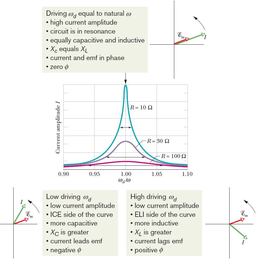
29 Notice that the max current depends on the impedence: I = E m R 2 + (X L X C ) 2 = E m /Z For a fixed R, I is max if X L = X C, so ω d L = 1/ω d C ω d = 1/ LC But if X L = X C, then φ = 0. This is called resonance!
30
31 Lecture Question 15.4 An inductor circuit operates at a frequency f = 120 Hz. The peak voltage is 120 V and the peak current through the inductor is 2.0 A. What is the inductance of the inductor in the circuit? (a) H (b) H (c) H (d) H (e) H
32 The power dissipated in the RLC circuit leaves through the resistor only: P = i 2 R = [I sin(ω d t φ)] 2 R = I 2 R sin 2 (ω d t φ) The average power is just P avg = I 2 R/2 Define: I rms = I/ 2 (root-mean-squared) This gives P avg = I 2 rmsr
33 A transformer changes one AC voltage to another AC voltage: A primary coil is wrapped around an iron core An emf is induced in a secondary coil also on the core The relationship between the two voltages is V s = V p N s N p

34 V s = V p N s N p Step-up transformer: N s > N p Step-down transformer: N p > N s Energy is conserved: I p V p = I s V s I s = I p N p /N s
1 Phasors and Alternating Currents
 Physics 4 Chapter : Alternating Current 0/5 Phasors and Alternating Currents alternating current: current that varies sinusoidally with time ac source: any device that supplies a sinusoidally varying potential
Physics 4B Chapter 31: Electromagnetic Oscillations and Alternating Current
 Physics 4B Chapter 31: Electromagnetic Oscillations and Alternating Current People of mediocre ability sometimes achieve outstanding success because they don't know when to quit. Most men succeed because
Inductance, Inductors, RL Circuits & RC Circuits, LC, and RLC Circuits
 Inductance, Inductors, RL Circuits & RC Circuits, LC, and RLC Circuits Self-inductance A time-varying current in a circuit produces an induced emf opposing the emf that initially set up the timevarying
Alternating Current Circuits
 Alternating Current Circuits AC Circuit An AC circuit consists of a combination of circuit elements and an AC generator or source. The output of an AC generator is sinusoidal and varies with time according
Inductance, RL and RLC Circuits
 Inductance, RL and RLC Circuits Inductance Temporarily storage of energy by the magnetic field When the switch is closed, the current does not immediately reach its maximum value. Faraday s law of electromagnetic
Electromagnetic Oscillations and Alternating Current. 1. Electromagnetic oscillations and LC circuit 2. Alternating Current 3.
 Electromagnetic Oscillations and Alternating Current 1. Electromagnetic oscillations and LC circuit 2. Alternating Current 3. RLC circuit in AC 1 RL and RC circuits RL RC Charging Discharging I = emf R
Chapter 33. Alternating Current Circuits
 Chapter 33 Alternating Current Circuits 1 Capacitor Resistor + Q = C V = I R R I + + Inductance d I Vab = L dt AC power source The AC power source provides an alternative voltage, Notation - Lower case
Chapter 30 Inductance
 Chapter 30 Inductance In this chapter we investigate the properties of an inductor in a circuit. There are two kinds of inductance mutual inductance and self-inductance. An inductor is formed by taken
Chapter 31: AC Circuits
 hapter 31: A ircuits A urrents and Voltages In this chapter, we discuss the behior of circuits driven by a source of A. Recall that A means, literally, alternating current. An alternating current is a
Alternating Current Circuits. Home Work Solutions
 Chapter 21 Alternating Current Circuits. Home Work s 21.1 Problem 21.11 What is the time constant of the circuit in Figure (21.19). 10 Ω 10 Ω 5.0 Ω 2.0µF 2.0µF 2.0µF 3.0µF Figure 21.19: Given: The circuit
Assessment Schedule 2015 Physics: Demonstrate understanding of electrical systems (91526)
") NCEA Level 3 Physics (91526) 2015 page 1 of 6 Assessment Schedule 2015 Physics: Demonstrate understanding of electrical systems (91526) Evidence Q Evidence Achievement Achievement with Merit Achievement
NCEA Level 3 Physics (91526) 2015 page 1 of 6 Assessment Schedule 2015 Physics: Demonstrate understanding of electrical systems (91526) Evidence Q Evidence Achievement Achievement with Merit Achievement
ELECTROMAGNETIC OSCILLATIONS AND ALTERNATING CURRENT
 Chapter 31: ELECTROMAGNETIC OSCILLATIONS AND ALTERNATING CURRENT 1 A charged capacitor and an inductor are connected in series At time t = 0 the current is zero, but the capacitor is charged If T is the
AC Circuits Homework Set
 Problem 1. In an oscillating LC circuit in which C=4.0 μf, the maximum potential difference across the capacitor during the oscillations is 1.50 V and the maximum current through the inductor is 50.0 ma.
Handout 10: Inductance. Self-Inductance and inductors
 1 Handout 10: Inductance Self-Inductance and inductors In Fig. 1, electric current is present in an isolate circuit, setting up magnetic field that causes a magnetic flux through the circuit itself. This
Inductance, RL Circuits, LC Circuits, RLC Circuits
 Inductance, R Circuits, C Circuits, RC Circuits Inductance What happens when we close the switch? The current flows What does the current look like as a function of time? Does it look like this? I t Inductance
CHAPTER 22 ELECTROMAGNETIC INDUCTION
 CHAPTER 22 ELECTROMAGNETIC INDUCTION PROBLEMS 47. REASONING AND Using Equation 22.7, we find emf 2 M I or M ( emf 2 ) t ( 0.2 V) ( 0.4 s) t I (.6 A) ( 3.4 A) 9.3 0 3 H 49. SSM REASONING AND From the results
Module 25: Outline Resonance & Resonance Driven & LRC Circuits Circuits 2
 Module 25: Driven RLC Circuits 1 Module 25: Outline Resonance & Driven LRC Circuits 2 Driven Oscillations: Resonance 3 Mass on a Spring: Simple Harmonic Motion A Second Look 4 Mass on a Spring (1) (2)
RLC Circuit (3) We can then write the differential equation for charge on the capacitor. The solution of this differential equation is
 We can then write the differential equation for charge on the capacitor. The solution of this differential equation is") RLC Circuit (3) We can then write the differential equation for charge on the capacitor The solution of this differential equation is (damped harmonic oscillation!), where 25 RLC Circuit (4) If we charge
RLC Circuit (3) We can then write the differential equation for charge on the capacitor The solution of this differential equation is (damped harmonic oscillation!), where 25 RLC Circuit (4) If we charge
Physics 115. AC: RL vs RC circuits Phase relationships RLC circuits. General Physics II. Session 33
 Session 33 Physics 115 General Physics II AC: RL vs RC circuits Phase relationships RLC circuits R. J. Wilkes Email: phy115a@u.washington.edu Home page: http://courses.washington.edu/phy115a/ 6/2/14 1
General Physics (PHY 2140)
") General Physics (PHY 2140) Lecture 10 6/12/2007 Electricity and Magnetism Induced voltages and induction Self-Inductance RL Circuits Energy in magnetic fields AC circuits and EM waves Resistors, capacitors
General Physics (PHY 2140) Lecture 10 6/12/2007 Electricity and Magnetism Induced voltages and induction Self-Inductance RL Circuits Energy in magnetic fields AC circuits and EM waves Resistors, capacitors
Chapter 32. Inductance
 Chapter 32 Inductance Joseph Henry 1797 1878 American physicist First director of the Smithsonian Improved design of electromagnet Constructed one of the first motors Discovered self-inductance Unit of
P441 Analytical Mechanics - I. RLC Circuits. c Alex R. Dzierba. In this note we discuss electrical oscillating circuits: undamped, damped and driven.
 Lecture 10 Monday - September 19, 005 Written or last updated: September 19, 005 P441 Analytical Mechanics - I RLC Circuits c Alex R. Dzierba Introduction In this note we discuss electrical oscillating
Assessment Schedule 2016 Physics: Demonstrate understanding electrical systems (91526)
") NCEA evel 3 Physics (91526) 2016 page 1 of 5 Assessment Schedule 2016 Physics: Demonstrate understanding electrical systems (91526) Evidence Statement NØ N1 N 2 A 3 A 4 M 5 M 6 E 7 E 8 0 1A 2A 3A 4A or
NCEA evel 3 Physics (91526) 2016 page 1 of 5 Assessment Schedule 2016 Physics: Demonstrate understanding electrical systems (91526) Evidence Statement NØ N1 N 2 A 3 A 4 M 5 M 6 E 7 E 8 0 1A 2A 3A 4A or
Physics for Scientists & Engineers 2
 Electromagnetic Oscillations Physics for Scientists & Engineers Spring Semester 005 Lecture 8! We have been working with circuits that have a constant current a current that increases to a constant current
Chapter 31: RLC Circuits. PHY2049: Chapter 31 1
 hapter 31: RL ircuits PHY049: hapter 31 1 L Oscillations onservation of energy Topics Damped oscillations in RL circuits Energy loss A current RMS quantities Forced oscillations Resistance, reactance,
Alternating Current. Symbol for A.C. source. A.C.
 Alternating Current Kirchoff s rules for loops and junctions may be used to analyze complicated circuits such as the one below, powered by an alternating current (A.C.) source. But the analysis can quickly
Self-inductance A time-varying current in a circuit produces an induced emf opposing the emf that initially set up the time-varying current.
 Inductance Self-inductance A time-varying current in a circuit produces an induced emf opposing the emf that initially set up the time-varying current. Basis of the electrical circuit element called an
Supplemental Notes on Complex Numbers, Complex Impedance, RLC Circuits, and Resonance
 Supplemental Notes on Complex Numbers, Complex Impedance, RLC Circuits, and Resonance Complex numbers Complex numbers are expressions of the form z = a + ib, where both a and b are real numbers, and i
Physics 142 AC Circuits Page 1. AC Circuits. I ve had a perfectly lovely evening but this wasn t it. Groucho Marx
 Physics 142 A ircuits Page 1 A ircuits I ve had a perfectly lovely evening but this wasn t it. Groucho Marx Alternating current: generators and values It is relatively easy to devise a source (a generator
Oscillations and Electromagnetic Waves. March 30, 2014 Chapter 31 1
 Oscillations and Electromagnetic Waves March 30, 2014 Chapter 31 1 Three Polarizers! Consider the case of unpolarized light with intensity I 0 incident on three polarizers! The first polarizer has a polarizing
Part 4: Electromagnetism. 4.1: Induction. A. Faraday's Law. The magnetic flux through a loop of wire is
 1 Part 4: Electromagnetism 4.1: Induction A. Faraday's Law The magnetic flux through a loop of wire is Φ = BA cos θ B A B = magnetic field penetrating loop [T] A = area of loop [m 2 ] = angle between field
Active Figure 32.3 (SLIDESHOW MODE ONLY)
") RL Circuit, Analysis An RL circuit contains an inductor and a resistor When the switch is closed (at time t = 0), the current begins to increase At the same time, a back emf is induced in the inductor
RL Circuit, Analysis An RL circuit contains an inductor and a resistor When the switch is closed (at time t = 0), the current begins to increase At the same time, a back emf is induced in the inductor
ALTERNATING CURRENT
 ATENATING UENT Important oints:. The alternating current (A) is generally expressed as ( ) I I sin ω t + φ Where i peak value of alternating current.. emf of an alternating current source is generally
Driven RLC Circuits Challenge Problem Solutions
 Driven LC Circuits Challenge Problem Solutions Problem : Using the same circuit as in problem 6, only this time leaving the function generator on and driving below resonance, which in the following pairs
12 Chapter Driven RLC Circuits
 hapter Driven ircuits. A Sources... -. A ircuits with a Source and One ircuit Element... -3.. Purely esistive oad... -3.. Purely Inductive oad... -6..3 Purely apacitive oad... -8.3 The Series ircuit...
Chapter 21: RLC Circuits. PHY2054: Chapter 21 1
 Chapter 21: RC Circuits PHY2054: Chapter 21 1 Voltage and Current in RC Circuits AC emf source: driving frequency f ε = ε sinωt ω = 2π f m If circuit contains only R + emf source, current is simple ε ε
Note 11: Alternating Current (AC) Circuits
 Circuits") Note 11: Alternating Current (AC) Circuits V R No phase difference between the voltage difference and the current and max For alternating voltage Vmax sin t, the resistor current is ir sin t. the instantaneous
Note 11: Alternating Current (AC) Circuits V R No phase difference between the voltage difference and the current and max For alternating voltage Vmax sin t, the resistor current is ir sin t. the instantaneous
I. Impedance of an R-L circuit.
 I. Impedance of an R-L circuit. [For inductor in an AC Circuit, see Chapter 31, pg. 1024] Consider the R-L circuit shown in Figure: 1. A current i(t) = I cos(ωt) is driven across the circuit using an AC
REACTANCE. By: Enzo Paterno Date: 03/2013
 REACTANCE REACTANCE By: Enzo Paterno Date: 03/2013 5/2007 Enzo Paterno 1 RESISTANCE - R i R (t R A resistor for all practical purposes is unaffected by the frequency of the applied sinusoidal voltage or
Circuits. David J. Starling Penn State Hazleton PHYS 212
 Invention is the most important product of man s creative brain. The ultimate purpose is the complete mastery of mind over the material world, the harnessing of human nature to human needs. - Nikola Tesla
Yell if you have any questions
 Class 31: Outline Hour 1: Concept Review / Overview PRS Questions possible exam questions Hour : Sample Exam Yell if you have any questions P31 1 Exam 3 Topics Faraday s Law Self Inductance Energy Stored
Chapter 31: RLC Circuits. PHY2049: Chapter 31 1
 Chapter 31: RLC Circuits PHY049: Chapter 31 1 LC Oscillations Conservation of energy Topics Dampe oscillations in RLC circuits Energy loss AC current RMS quantities Force oscillations Resistance, reactance,
Alternating Current. Chapter 31. PowerPoint Lectures for University Physics, Twelfth Edition Hugh D. Young and Roger A. Freedman
 Chapter 31 Alternating Current PowerPoint Lectures for University Physics, Twelfth Edition Hugh D. Young and Roger A. Freedman Lectures by James Pazun Modified by P. Lam 8_8_2008 Topics for Chapter 31
Chapter 31 Electromagnetic Oscillations and Alternating Current LC Oscillations, Qualitatively
 Chapter 3 Electromagnetic Oscillations and Alternating Current LC Oscillations, Qualitatively In the LC circuit the charge, current, and potential difference vary sinusoidally (with period T and angular
Self-Inductance. Φ i. Self-induction. = (if flux Φ 1 through 1 loop. Tm Vs A A. Lecture 11-1
 Lecture - Self-Inductance As current i through coil increases, magnetic flux through itself increases. This in turn induces back emf in the coil itself When current i is decreasing, emf is induced again
Chapter 32A AC Circuits. A PowerPoint Presentation by Paul E. Tippens, Professor of Physics Southern Polytechnic State University
 Chapter 32A AC Circuits A PowerPoint Presentation by Paul E. Tippens, Professor of Physics Southern Polytechnic State University 2007 Objectives: After completing this module, you should be able to: Describe
David J. Starling Penn State Hazleton PHYS 212
 and and The term inductance was coined by Oliver Heaviside in February 1886. David J. Starling Penn State Hazleton PHYS 212 and We have seen electric flux: Φ E = E d A But we can define the magnetic flux
Solutions to these tests are available online in some places (but not all explanations are good)...
...") The Physics GRE Sample test put out by ETS https://www.ets.org/s/gre/pdf/practice_book_physics.pdf OSU physics website has lots of tips, and 4 additional tests http://www.physics.ohiostate.edu/undergrad/ugs_gre.php
The Physics GRE Sample test put out by ETS https://www.ets.org/s/gre/pdf/practice_book_physics.pdf OSU physics website has lots of tips, and 4 additional tests http://www.physics.ohiostate.edu/undergrad/ugs_gre.php
PHYS 1441 Section 001 Lecture #23 Monday, Dec. 4, 2017
 PHYS 1441 Section 1 Lecture #3 Monday, Dec. 4, 17 Chapter 3: Inductance Mutual and Self Inductance Energy Stored in Magnetic Field Alternating Current and AC Circuits AC Circuit W/ LRC Chapter 31: Maxwell
Module 24: Outline. Expt. 8: Part 2:Undriven RLC Circuits
 Module 24: Undriven RLC Circuits 1 Module 24: Outline Undriven RLC Circuits Expt. 8: Part 2:Undriven RLC Circuits 2 Circuits that Oscillate (LRC) 3 Mass on a Spring: Simple Harmonic Motion (Demonstration)
ELEC ELE TRO TR MAGNETIC INDUCTION
 ELECTRO MAGNETIC INDUCTION Faraday Henry 1791-1867 1797 1878 Laws:- Faraday s Laws :- 1) When ever there is a change in magnetic flux linked with a coil, a current is generated in the coil. The current
Name:... Section:... Physics 208 Quiz 8. April 11, 2008; due April 18, 2008
 Name:... Section:... Problem 1 (6 Points) Physics 8 Quiz 8 April 11, 8; due April 18, 8 Consider the AC circuit consisting of an AC voltage in series with a coil of self-inductance,, and a capacitor of
Ch. 23 Electromagnetic Induction, AC Circuits, And Electrical Technologies
 Ch. 23 Electromagnetic Induction, AC Circuits, And Electrical Technologies Induced emf - Faraday s Experiment When a magnet moves toward a loop of wire, the ammeter shows the presence of a current When
AC Circuits III. Physics 2415 Lecture 24. Michael Fowler, UVa
 AC Circuits III Physics 415 Lecture 4 Michael Fowler, UVa Today s Topics LC circuits: analogy with mass on spring LCR circuits: damped oscillations LCR circuits with ac source: driven pendulum, resonance.
RLC Series Circuit. We can define effective resistances for capacitors and inductors: 1 = Capacitive reactance:
 RLC Series Circuit In this exercise you will investigate the effects of changing inductance, capacitance, resistance, and frequency on an RLC series AC circuit. We can define effective resistances for
Lecture 39. PHYC 161 Fall 2016
 Lecture 39 PHYC 161 Fall 016 Announcements DO THE ONLINE COURSE EVALUATIONS - response so far is < 8 % Magnetic field energy A resistor is a device in which energy is irrecoverably dissipated. By contrast,
Exam 3 Topics. Displacement Current Poynting Vector. Faraday s Law Self Inductance. Circuits. Energy Stored in Inductor/Magnetic Field
 Exam 3 Topics Faraday s Law Self Inductance Energy Stored in Inductor/Magnetic Field Circuits LR Circuits Undriven (R)LC Circuits Driven RLC Circuits Displacement Current Poynting Vector NO: B Materials,
 Alternating Currents. The power is transmitted from a power house on high voltage ac because (a) Electric current travels faster at higher volts (b) It is more economical due to less power wastage (c)
Sinusoidal Response of RLC Circuits
 Sinusoidal Response of RLC Circuits Series RL circuit Series RC circuit Series RLC circuit Parallel RL circuit Parallel RC circuit R-L Series Circuit R-L Series Circuit R-L Series Circuit Instantaneous
Source-Free RC Circuit
 First Order Circuits Source-Free RC Circuit Initial charge on capacitor q = Cv(0) so that voltage at time 0 is v(0). What is v(t)? Prof Carruthers (ECE @ BU) EK307 Notes Summer 2018 150 / 264 First Order
Inductive & Capacitive Circuits. Subhasish Chandra Assistant Professor Department of Physics Institute of Forensic Science, Nagpur
 Inductive & Capacitive Circuits Subhasish Chandra Assistant Professor Department of Physics Institute of Forensic Science, Nagpur LR Circuit LR Circuit (Charging) Let us consider a circuit having an inductance
Lecture 27: FRI 20 MAR
 Physics 2102 Jonathan Dowling Lecture 27: FRI 20 MAR Ch.30.7 9 Inductors & Inductance Nikolai Tesla Inductors: Solenoids Inductors are with respect to the magnetic field what capacitors are with respect
CLUSTER LEVEL WORK SHOP
 CLUSTER LEVEL WORK SHOP SUBJECT PHYSICS QUESTION BANK (ALTERNATING CURRENT ) DATE: 0/08/06 What is the phase difference between the voltage across the inductance and capacitor in series AC circuit? Ans.
Lecture 24. Impedance of AC Circuits.
 Lecture 4. Impedance of AC Circuits. Don t forget to complete course evaluations: https://sakai.rutgers.edu/portal/site/sirs Post-test. You are required to attend one of the lectures on Thursday, Dec.
Capacitor and Inductor
 Capacitor and Inductor Copyright (c) 2015 2017 Young W. Lim. Permission is granted to copy, distribute and/or modify this document under the terms of the GNU Free Documentation License, Version 1.2 or
Capacitor and Inductor
 Capacitor and Inductor Copyright (c) 2015 2017 Young W. Lim. Permission is granted to copy, distribute and/or modify this document under the terms of the GNU Free Documentation License, Version 1.2 or
ALTERNATING CURRENT. with X C = 0.34 A. SET UP: The specified value is the root-mean-square current; I. EXECUTE: (a) V = (0.34 A) = 0.12 A.
 V = (0.34 A) = 0.12 A.") ATENATING UENT 3 3 IDENTIFY: i Icosωt and I I/ SET UP: The specified value is the root-mean-square current; I 34 A EXEUTE: (a) I 34 A (b) I I (34 A) 48 A (c) Since the current is positive half of the time
ATENATING UENT 3 3 IDENTIFY: i Icosωt and I I/ SET UP: The specified value is the root-mean-square current; I 34 A EXEUTE: (a) I 34 A (b) I I (34 A) 48 A (c) Since the current is positive half of the time
PES 1120 Spring 2014, Spendier Lecture 35/Page 1
 PES 0 Spring 04, Spendier Lecture 35/Page Today: chapter 3 - LC circuits We have explored the basic physics of electric and magnetic fields and how energy can be stored in capacitors and inductors. We
Lecture 4: R-L-C Circuits and Resonant Circuits
 Lecture 4: R-L-C Circuits and Resonant Circuits RLC series circuit: What's V R? Simplest way to solve for V is to use voltage divider equation in complex notation: V X L X C V R = in R R + X C + X L L
Inductors. Hydraulic analogy Duality with capacitor Charging and discharging. Lecture 12: Inductors
 Lecture 12: nductors nductors Hydraulic analogy Duality with capacitor Charging and discharging Robert R. McLeod, University of Colorado http://hilaroad.com/camp/projects/magnet.html 99 Lecture 12: nductors
Gen. Phys. II Exam 2 - Chs. 21,22,23 - Circuits, Magnetism, EM Induction Mar. 5, 2018
 Gen. Phys. II Exam 2 - Chs. 21,22,23 - Circuits, Magnetism, EM Induction Mar. 5, 2018 Rec. Time Name For full credit, make your work clear. Show formulas used, essential steps, and results with correct
MODULE I. Transient Response:
 Transient Response: MODULE I The Transient Response (also known as the Natural Response) is the way the circuit responds to energies stored in storage elements, such as capacitors and inductors. If a capacitor
Lecture 35: FRI 17 APR Electrical Oscillations, LC Circuits, Alternating Current I
 Physics 3 Jonathan Dowling Lecture 35: FRI 7 APR Electrical Oscillations, LC Circuits, Alternating Current I Nikolai Tesla What are we going to learn? A road map Electric charge è Electric force on other
Course Updates. Reminders: 1) Assignment #10 due Today. 2) Quiz # 5 Friday (Chap 29, 30) 3) Start AC Circuits
 Assignment #10 due Today. 2) Quiz # 5 Friday (Chap 29, 30) 3) Start AC Circuits") ourse Updates http://www.phys.hawaii.edu/~varner/phys272-spr10/physics272.html eminders: 1) Assignment #10 due Today 2) Quiz # 5 Friday (hap 29, 30) 3) Start A ircuits Alternating urrents (hap 31) In this
ourse Updates http://www.phys.hawaii.edu/~varner/phys272-spr10/physics272.html eminders: 1) Assignment #10 due Today 2) Quiz # 5 Friday (hap 29, 30) 3) Start A ircuits Alternating urrents (hap 31) In this
Louisiana State University Physics 2102, Exam 3 April 2nd, 2009.
 PRINT Your Name: Instructor: Louisiana State University Physics 2102, Exam 3 April 2nd, 2009. Please be sure to PRINT your name and class instructor above. The test consists of 4 questions (multiple choice),
AC Source and RLC Circuits
 X X L C = 2π fl = 1/2π fc 2 AC Source and RLC Circuits ( ) 2 Inductive reactance Capacitive reactance Z = R + X X Total impedance L C εmax Imax = Z XL XC tanφ = R Maximum current Phase angle PHY2054: Chapter
REVIEW EXERCISES. 2. What is the resulting action if switch (S) is opened after the capacitor (C) is fully charged? Se figure 4.27.
 is opened after the capacitor (C) is fully charged? Se figure 4.27.") REVIEW EXERCISES Circle the letter of the correct answer to each question. 1. What is the current and voltage relationship immediately after the switch is closed in the circuit in figure 4-27, which shows
REVIEW EXERCISES Circle the letter of the correct answer to each question. 1. What is the current and voltage relationship immediately after the switch is closed in the circuit in figure 4-27, which shows
Electromagnetic Induction (Chapters 31-32)
") Electromagnetic Induction (Chapters 31-3) The laws of emf induction: Faraday s and Lenz s laws Inductance Mutual inductance M Self inductance L. Inductors Magnetic field energy Simple inductive circuits
Electromagnetic Induction (Chapters 31-3) The laws of emf induction: Faraday s and Lenz s laws Inductance Mutual inductance M Self inductance L. Inductors Magnetic field energy Simple inductive circuits
ELECTRO MAGNETIC INDUCTION
 ELECTRO MAGNETIC INDUCTION 1) A Circular coil is placed near a current carrying conductor. The induced current is anti clock wise when the coil is, 1. Stationary 2. Moved away from the conductor 3. Moved
Chapter 32. Inductance
 Chapter 32 Inductance Inductance Self-inductance A time-varying current in a circuit produces an induced emf opposing the emf that initially set up the time-varying current. Basis of the electrical circuit
SUMMARY Phys 2523 (University Physics II) Compiled by Prof. Erickson. F e (r )=q E(r ) dq r 2 ˆr = k e E = V. V (r )=k e r = k q i. r i r.
 Compiled by Prof. Erickson. F e (r )=q E(r ) dq r 2 ˆr = k e E = V. V (r )=k e r = k q i. r i r.") SUMMARY Phys 53 (University Physics II) Compiled by Prof. Erickson q 1 q Coulomb s Law: F 1 = k e r ˆr where k e = 1 4π =8.9875 10 9 N m /C, and =8.85 10 1 C /(N m )isthepermittivity of free space. Generally,
SUMMARY Phys 53 (University Physics II) Compiled by Prof. Erickson q 1 q Coulomb s Law: F 1 = k e r ˆr where k e = 1 4π =8.9875 10 9 N m /C, and =8.85 10 1 C /(N m )isthepermittivity of free space. Generally,
Capacitor. Capacitor (Cont d)
") 1 2 1 Capacitor Capacitor is a passive two-terminal component storing the energy in an electric field charged by the voltage across the dielectric. Fixed Polarized Variable Capacitance is the ratio of
1 2 1 Capacitor Capacitor is a passive two-terminal component storing the energy in an electric field charged by the voltage across the dielectric. Fixed Polarized Variable Capacitance is the ratio of
Basics of Electric Circuits
 António Dente Célia de Jesus February 2014 1 Alternating Current Circuits 1.1 Using Phasors There are practical and economic reasons justifying that electrical generators produce emf with alternating and
Handout 11: AC circuit. AC generator
 Handout : AC circuit AC generator Figure compares the voltage across the directcurrent (DC) generator and that across the alternatingcurrent (AC) generator For DC generator, the voltage is constant For
Exam 2 Solutions. Note that there are several variations of some problems, indicated by choices in parentheses.
 Exam 2 Solutions Note that there are several variations of some problems, indicated by choices in parentheses. Problem 1 Part of a long, straight insulated wire carrying current i is bent into a circular
SCHOOL OF MATHEMATICS MATHEMATICS FOR PART I ENGINEERING. Self-paced Course
 SCHOOL OF MATHEMATICS MATHEMATICS FOR PART I ENGINEERING Self-paced Course MODULE 26 APPLICATIONS TO ELECTRICAL CIRCUITS Module Topics 1. Complex numbers and alternating currents 2. Complex impedance 3.
EXPERIMENT 07 TO STUDY DC RC CIRCUIT AND TRANSIENT PHENOMENA
 EXPERIMENT 07 TO STUDY DC RC CIRCUIT AND TRANSIENT PHENOMENA DISCUSSION The capacitor is a element which stores electric energy by charging the charge on it. Bear in mind that the charge on a capacitor
Physics 11b Lecture #15
 Physics 11b ecture #15 and ircuits A ircuits S&J hapter 3 & 33 Administravia Midterm # is Thursday If you can t take midterm, you MUST let us (me, arol and Shaun) know in writing before Wednesday noon
INDUCTANCE Self Inductance
 NDUTANE 3. Self nductance onsider the circuit shown in the Figure. When the switch is closed the current, and so the magnetic field, through the circuit increases from zero to a specific value. The increasing
A capacitor is a device that stores electric charge (memory devices). A capacitor is a device that stores energy E = Q2 2C = CV 2
. A capacitor is a device that stores energy E = Q2 2C = CV 2") Capacitance: Lecture 2: Resistors and Capacitors Capacitance (C) is defined as the ratio of charge (Q) to voltage (V) on an object: C = Q/V = Coulombs/Volt = Farad Capacitance of an object depends on geometry
Capacitance: Lecture 2: Resistors and Capacitors Capacitance (C) is defined as the ratio of charge (Q) to voltage (V) on an object: C = Q/V = Coulombs/Volt = Farad Capacitance of an object depends on geometry
R-L-C Circuits and Resonant Circuits
 P517/617 Lec4, P1 R-L-C Circuits and Resonant Circuits Consider the following RLC series circuit What's R? Simplest way to solve for is to use voltage divider equation in complex notation. X L X C in 0
Chapter 30 Self Inductance, Inductors & DC Circuits Revisited
 Chapter 30 Self Inductance, Inductors & DC Circuits Revisited Self-Inductance and Inductors Self inductance determines the magnetic flux in a circuit due to the circuit s own current. B = LI Every circuit
PHYS Fields and Waves
 PHYS 2421 - Fields and Waves Idea: how to deal with alternating currents Edison wanted direct current, Tesla alternating current, who won? Mathematically: Instantaneous current: Instantaneous voltage:
General Physics (PHY 2140)
") General Physics (PHY 40) eminder: Exam this Wednesday 6/3 ecture 0-4 4 questions. Electricity and Magnetism nduced voltages and induction Self-nductance Circuits Energy in magnetic fields AC circuits and
General Physics (PHY 40) eminder: Exam this Wednesday 6/3 ecture 0-4 4 questions. Electricity and Magnetism nduced voltages and induction Self-nductance Circuits Energy in magnetic fields AC circuits and
b) (4) How large is the current through the 2.00 Ω resistor, and in which direction?
 (4) How large is the current through the 2.00 Ω resistor, and in which direction?") General Physics II Exam 2 - Chs. 19 21 - Circuits, Magnetism, EM Induction - Sep. 29, 2016 Name Rec. Instr. Rec. Time For full credit, make your work clear. Show formulas used, essential steps, and results
General Physics II Exam 2 - Chs. 19 21 - Circuits, Magnetism, EM Induction - Sep. 29, 2016 Name Rec. Instr. Rec. Time For full credit, make your work clear. Show formulas used, essential steps, and results
Learnabout Electronics - AC Theory
 Learnabout Electronics - AC Theory Facts & Formulae for AC Theory www.learnabout-electronics.org Contents AC Wave Values... 2 Capacitance... 2 Charge on a Capacitor... 2 Total Capacitance... 2 Inductance...
20. Alternating Currents
 University of hode sland DigitalCommons@U PHY 204: Elementary Physics Physics Course Materials 2015 20. lternating Currents Gerhard Müller University of hode sland, gmuller@uri.edu Creative Commons License
Sinusoidal Steady-State Analysis
 Chapter 4 Sinusoidal Steady-State Analysis In this unit, we consider circuits in which the sources are sinusoidal in nature. The review section of this unit covers most of section 9.1 9.9 of the text.
Chapter 10: Sinusoidal Steady-State Analysis
 Chapter 10: Sinusoidal Steady-State Analysis 1 Objectives : sinusoidal functions Impedance use phasors to determine the forced response of a circuit subjected to sinusoidal excitation Apply techniques
Consider a simple RC circuit. We might like to know how much power is being supplied by the source. We probably need to find the current.
 AC power Consider a simple RC circuit We might like to know how much power is being supplied by the source We probably need to find the current R 10! R 10! is VS Vmcosωt Vm 10 V f 60 Hz V m 10 V C 150