MODULE I. Transient Response:
|
|
|
- Stanley Nelson
- 6 years ago
- Views:
Transcription
1 Transient Response: MODULE I The Transient Response (also known as the Natural Response) is the way the circuit responds to energies stored in storage elements, such as capacitors and inductors. If a capacitor has energy stored within it, then that energy can be dissipated/absorbed by a resistor. How that energy is dissipated is the Transient Response. A resistor capacitor circuit (RC circuit) or RC network, is an electric circuit composed of resistors and capacitors driven by a voltage or current source A resistor inductor circuit (RL circuit) or RL network, is an electric circuit composed of resistors and inductors driven by a voltage or current source Transient Response of RC circuit When an increasing DC voltage is applied to a discharged Capacitor, the capacitor draws a charging current and charges up, and when the voltage is reduced, the capacitor discharges

2 in the opposite direction. Because capacitors are able to store electrical energy they act like small batteries and can store or release the energy as required. The charge on the plates of the capacitor is given as: Q = CV. This charging (storage) and discharging (release) of a capacitors energy is never instant but takes a certain amount of time to occur with the time taken for the capacitor to charge or discharge to within a certain percentage of its maximum supply value being known as its Time Constant ( τ ). The Transient (step) response of the RC circuit as shown V ( t) V for t for t Applying KCL to the circuit V ( t) Vout( t) dvout C R dt dvout Vout( t) V ( t) dt RC RC WKT V out ( t) A Be () () Substitute Equation () into () A RC A RC B RC V RC V RC B e t B RC B e t
 V Ve ( t)")

.")
3 The required output voltage Vout Time-Constant RC V V out out ( t) V Ve ( t) V ( e t RC t RC ) The time taken for the capacitor to charge or discharge to within a certain percentage of its maximum supply value is known as its Time Constant (τ). Mathematically, τ=rc
4 From the RC circuit Curve, Notice the second term starts from V and exponentially decay to. It will never reach, but approach to asymptotically. As a result Vout starts from and asymptotically approach to V. Series RC Circuit: If the switch in this circuit was initially open, and then closed at time t=, the current in this circuit is: i t) I ( t exp Where I V = the initial current in thee circuit R RC = the time constant for the circuit Another definition of τ is obtained by setting t=τ in i(t). It gives i(τ)=i*(/e). The time constant of an RC circuit is the time required for the current in the circuit to fall to /e of its initial value. Transient Response of RL circuits A RL Series Circuit consists basically of an inductor of inductance L connected in series with a resistor of resistance R. The resistance R is the DC resistive value of the wire turns or loops that goes into making up the inductors coil. Consider the RL series circuit below.


5 The above RL series circuit is connected across a constant voltage source, (the battery) and a switch. Assume that the switch, S is open until it is closed at a time t =, and then remains permanently closed producing a step response type voltage input. The current, i begins to flow through the circuit but does not rise rapidly to its maximum value of Imax as determined by the ratio of V / R (Ohms Law). Applying KVL to the circuit, to define the individual voltage drops that exist around the circuit and then hopefully use it to give us an expression for the flow of current. V( t) V R V L The voltage across the resistor R is IR (ohms law) V R I R The Voltage drop across the Inductor is di V L L dt The individual voltage drops around the LR series circuit can be given as: V ( t) I R L di dt
6 Series RL Circuits: If the switch in this circuit is initially open, and then closed at time t=, the current in this circuit will be described as: i( t) I ( e t ) Where I V = the limiting value of the current in the circuit R L R = the time constant for the circuit Transient response of RLC Circuit Series RLC circuit In theory, there are three cases for the way a series RLC circuit will respond when the switch is closed at time t=. In this lab, only the underdamped case will be dealt with. For this case, the current in the circuit is described by: V i exp( t)sin( dt) L d
7 Where d and R LC L Current in undamped RLC circuit The current in the circuit oscillates due to the sine component in Equation i, but the maximum value it can reach is decaying due to the negative exponential. The envelope that the current must fall within is described by: V i exp( t) or i L d V exp( t) L d The quantity α is referred to as the time constant of the envelope. It is determined by taking the natural logarithm of both sides of the above equation: ln i V ln t d L Which is a linear equation. Transient Response of LC circuit: If the limit R tents to, the series RLC circuit reduces to the Lossless LC circuit
8 The equation that describes the response of this circuit is d vc vc dt LC Assuming a solution of the form Ae -st the characteristic equation is s Where LC The roots are s j s j And the solution is a linear combination of Ae st and Ae st vc( t) jot A e A e j t o By using Euler s relation Equation vc t) Bcos( t) Bsin( ) ( t The constants A, A or B, B are determined from the initial conditions of the system. For vc(t=)=v and for dvc(t=)/dt = (no current flowing in the circuit initially ), And A A V j A j A Which give And the solution becomes The current flowing in the circuit is A A V V j ( ) ( t jt vc t e e ) V cos( ) t dvc i C CV sin( t) dt
9 And the voltage across the inductor is easily determined from KVL or from the element relation of the inductor vl= L di/dt vl vc V cos( t) Step and sinusoidal inputs using Laplace transform method Unit Step Function, t ( t), t
 ( s) s As before, start with the definition of the Laplace transform")
10 To find the Laplace Transform, we apply the definition ( s) ( t) e. e s s st dt s st dt e st So Sinusoidal Function L ( t) ( s) s As before, start with the definition of the Laplace transform Here it becomes useful to use Euler's identity for the sine
 with a constant driving electro-motive force (emf) E.")
11 So Let's put this over a common denominator Natural Frequency and Damping Ratio Damping and Natural response of RLC circuit Consider a series RLC circuit (one that has a resistor, an inductor and a capacitor) with a constant driving electro-motive force (emf) E. The current equation for the circuit is
12 di L Ri idt E dt C This is equivalent: di L Ri q E dt C Differentiating, we have d i dt Auxiliary Equation L R i di dt R L R L i C Lm Rm C withroots : m m R 4L C L R 4L L C R Now is called the damping coefficient of the circuit L is the resonant frequency of the circuit LC m, m are called the natural frequencies of the circuit. The nature of the current will depend on the relationship between R,L and C. The form of the roots m, m depends on the values of α and ω. The following three case are possible.
13 . α= ω : Critically Damped System. m and m are equal and real numbers: no oscillatory behaviour.. α > ω : Over Damped System:m and m are real numbers but unequal: no oscillatory behaviour. 3. α < ω : Under Damped System. m and m are complex numbers. System exhibits oscillatory behaviour. Logarithmic Decrement The logarithmic decrement represents the rate at which the amplitude of a free damped vibration decreases. It is defined as the natural logarithm of the ratio of any two successive amplitudes. It is found from the time response of underdamped vibration (oscilloscope or realtime analyser). Logarithmic decrement, is used to find the damping ratio of an underdamped system in the time domain. The logarithmic decrement is the natural log of the ratio of the amplitudes of any two successive peaks: ln n x( t) x( t nt) Where x(t) is the amplitude at time t and x (t+ nt) is the amplitude of the peak n periods away, where n is any integer number of successive, positive peaks. The damping ratio is then found from the logarithmic decrement: Thus logarithmic decrement also permits to evaluate the Q factor of the system:
14 ) ( ) ( ln nt t x t x n Q Q The damping ratio can then be used to find the natural frequency ωn, of vibration of the system from the damped natural frequency ωd: d n d d Where T, the period of the waveform, is the time between two successive amplitude peaks of the underdamped system. The method of logarithmic decrement becomes less and less precise as the damping ratio increases past about.5; it does not apply at all for a damping ratio greater than. because the system is overdamped. Simplified Variation The damping ratio can be found for any two adjacent peaks. This method is used when n= and is derived from the general method above: ln x x Where x and x are any two successive peaks And for system << (not too close to the critically damped regime, where =). ln x x Response to non-sinusoidal periodic inputs

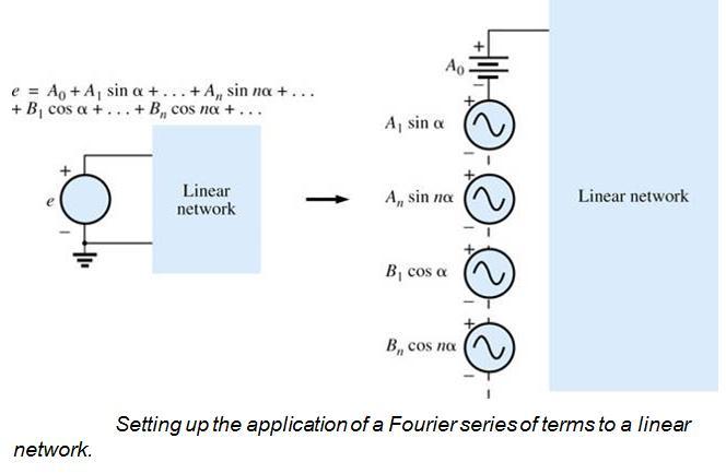
15 Any waveform that differs from the basic description of the sinusoidal waveform is referred to as nonsinusoidal. The most obvious and familiar are the dc, square-wave, triangular, sawtooth, and rectified waveforms. Fourier series refers to a series of terms, developed in 8 by Baron Jean Fourier that can be used to represent a nonsinusoidal periodic waveform. In the analysis of these waveforms, we solve for each term in the Fourier series: The Fourier series representation of a nonsinusoidal input can be applied to a linear network using the principle of superposition. Recall that this theorem allowed us to consider the effects of each source of a circuit independently. If we replace the nonsinusoidal input with the terms of the Fourier series deemed necessary for practical considerations, we can use superposition to find the response of the network to each term.
16
ENGR 2405 Chapter 8. Second Order Circuits
 ENGR 2405 Chapter 8 Second Order Circuits Overview The previous chapter introduced the concept of first order circuits. This chapter will expand on that with second order circuits: those that need a second
To find the step response of an RC circuit
 To find the step response of an RC circuit v( t) v( ) [ v( t) v( )] e tt The time constant = RC The final capacitor voltage v() The initial capacitor voltage v(t ) To find the step response of an RL circuit
Handout 10: Inductance. Self-Inductance and inductors
 1 Handout 10: Inductance Self-Inductance and inductors In Fig. 1, electric current is present in an isolate circuit, setting up magnetic field that causes a magnetic flux through the circuit itself. This
Basic RL and RC Circuits R-L TRANSIENTS: STORAGE CYCLE. Engineering Collage Electrical Engineering Dep. Dr. Ibrahim Aljubouri
 st Class Basic RL and RC Circuits The RL circuit with D.C (steady state) The inductor is short time at Calculate the inductor current for circuits shown below. I L E R A I L E R R 3 R R 3 I L I L R 3 R
Inductance, Inductors, RL Circuits & RC Circuits, LC, and RLC Circuits
 Inductance, Inductors, RL Circuits & RC Circuits, LC, and RLC Circuits Self-inductance A time-varying current in a circuit produces an induced emf opposing the emf that initially set up the timevarying
RC, RL, and LCR Circuits
 RC, RL, and LCR Circuits EK307 Lab Note: This is a two week lab. Most students complete part A in week one and part B in week two. Introduction: Inductors and capacitors are energy storage devices. They
Response of Second-Order Systems
 Unit 3 Response of SecondOrder Systems In this unit, we consider the natural and step responses of simple series and parallel circuits containing inductors, capacitors and resistors. The equations which
EE292: Fundamentals of ECE
 EE292: Fundamentals of ECE Fall 2012 TTh 10:00-11:15 SEB 1242 Lecture 14 121011 http://www.ee.unlv.edu/~b1morris/ee292/ 2 Outline Review Steady-State Analysis RC Circuits RL Circuits 3 DC Steady-State
Electromagnetic Oscillations and Alternating Current. 1. Electromagnetic oscillations and LC circuit 2. Alternating Current 3.
 Electromagnetic Oscillations and Alternating Current 1. Electromagnetic oscillations and LC circuit 2. Alternating Current 3. RLC circuit in AC 1 RL and RC circuits RL RC Charging Discharging I = emf R
Source-Free RC Circuit
 First Order Circuits Source-Free RC Circuit Initial charge on capacitor q = Cv(0) so that voltage at time 0 is v(0). What is v(t)? Prof Carruthers (ECE @ BU) EK307 Notes Summer 2018 150 / 264 First Order
ELECTROMAGNETIC OSCILLATIONS AND ALTERNATING CURRENT
 Chapter 31: ELECTROMAGNETIC OSCILLATIONS AND ALTERNATING CURRENT 1 A charged capacitor and an inductor are connected in series At time t = 0 the current is zero, but the capacitor is charged If T is the
Chapter 4 Transients. Chapter 4 Transients
 Chapter 4 Transients Chapter 4 Transients 1. Solve first-order RC or RL circuits. 2. Understand the concepts of transient response and steady-state response. 1 3. Relate the transient response of first-order
Electric Circuit Theory
 Electric Circuit Theory Nam Ki Min nkmin@korea.ac.kr 010-9419-2320 Chapter 8 Natural and Step Responses of RLC Circuits Nam Ki Min nkmin@korea.ac.kr 010-9419-2320 8.1 Introduction to the Natural Response
EXPERIMENT 07 TO STUDY DC RC CIRCUIT AND TRANSIENT PHENOMENA
 EXPERIMENT 07 TO STUDY DC RC CIRCUIT AND TRANSIENT PHENOMENA DISCUSSION The capacitor is a element which stores electric energy by charging the charge on it. Bear in mind that the charge on a capacitor
Alternating Current Circuits. Home Work Solutions
 Chapter 21 Alternating Current Circuits. Home Work s 21.1 Problem 21.11 What is the time constant of the circuit in Figure (21.19). 10 Ω 10 Ω 5.0 Ω 2.0µF 2.0µF 2.0µF 3.0µF Figure 21.19: Given: The circuit
Physics 116A Notes Fall 2004
 Physics 116A Notes Fall 2004 David E. Pellett Draft v.0.9 Notes Copyright 2004 David E. Pellett unless stated otherwise. References: Text for course: Fundamentals of Electrical Engineering, second edition,
Active Figure 32.3 (SLIDESHOW MODE ONLY)
") RL Circuit, Analysis An RL circuit contains an inductor and a resistor When the switch is closed (at time t = 0), the current begins to increase At the same time, a back emf is induced in the inductor
RL Circuit, Analysis An RL circuit contains an inductor and a resistor When the switch is closed (at time t = 0), the current begins to increase At the same time, a back emf is induced in the inductor
Inductance, RL and RLC Circuits
 Inductance, RL and RLC Circuits Inductance Temporarily storage of energy by the magnetic field When the switch is closed, the current does not immediately reach its maximum value. Faraday s law of electromagnetic
Lecture 39. PHYC 161 Fall 2016
 Lecture 39 PHYC 161 Fall 016 Announcements DO THE ONLINE COURSE EVALUATIONS - response so far is < 8 % Magnetic field energy A resistor is a device in which energy is irrecoverably dissipated. By contrast,
8. Introduction and Chapter Objectives
 Real Analog - Circuits Chapter 8: Second Order Circuits 8. Introduction and Chapter Objectives Second order systems are, by definition, systems whose input-output relationship is a second order differential
Chapter 32. Inductance
 Chapter 32 Inductance Joseph Henry 1797 1878 American physicist First director of the Smithsonian Improved design of electromagnet Constructed one of the first motors Discovered self-inductance Unit of
Self-inductance A time-varying current in a circuit produces an induced emf opposing the emf that initially set up the time-varying current.
 Inductance Self-inductance A time-varying current in a circuit produces an induced emf opposing the emf that initially set up the time-varying current. Basis of the electrical circuit element called an
Chapter 30 Inductance
 Chapter 30 Inductance In this chapter we investigate the properties of an inductor in a circuit. There are two kinds of inductance mutual inductance and self-inductance. An inductor is formed by taken
EE 242 EXPERIMENT 8: CHARACTERISTIC OF PARALLEL RLC CIRCUIT BY USING PULSE EXCITATION 1
 EE 242 EXPERIMENT 8: CHARACTERISTIC OF PARALLEL RLC CIRCUIT BY USING PULSE EXCITATION 1 PURPOSE: To experimentally study the behavior of a parallel RLC circuit by using pulse excitation and to verify that
Electrical Circuits (2)
") Electrical Circuits (2) Lecture 7 Transient Analysis Dr.Eng. Basem ElHalawany Extra Reference for this Lecture Chapter 16 Schaum's Outline Of Theory And Problems Of Electric Circuits https://archive.org/details/theoryandproblemsofelectriccircuits
Electrical Circuits (2) Lecture 7 Transient Analysis Dr.Eng. Basem ElHalawany Extra Reference for this Lecture Chapter 16 Schaum's Outline Of Theory And Problems Of Electric Circuits https://archive.org/details/theoryandproblemsofelectriccircuits
The RLC circuits have a wide range of applications, including oscillators and frequency filters
 9. The RL ircuit The RL circuits have a wide range of applications, including oscillators and frequency filters This chapter considers the responses of RL circuits The result is a second-order differential
EECE251. Circuit Analysis I. Set 4: Capacitors, Inductors, and First-Order Linear Circuits
 EECE25 Circuit Analysis I Set 4: Capacitors, Inductors, and First-Order Linear Circuits Shahriar Mirabbasi Department of Electrical and Computer Engineering University of British Columbia shahriar@ece.ubc.ca
EM Oscillations. David J. Starling Penn State Hazleton PHYS 212
 I ve got an oscillating fan at my house. The fan goes back and forth. It looks like the fan is saying No. So I like to ask it questions that a fan would say no to. Do you keep my hair in place? Do you
Assessment Schedule 2015 Physics: Demonstrate understanding of electrical systems (91526)
") NCEA Level 3 Physics (91526) 2015 page 1 of 6 Assessment Schedule 2015 Physics: Demonstrate understanding of electrical systems (91526) Evidence Q Evidence Achievement Achievement with Merit Achievement
NCEA Level 3 Physics (91526) 2015 page 1 of 6 Assessment Schedule 2015 Physics: Demonstrate understanding of electrical systems (91526) Evidence Q Evidence Achievement Achievement with Merit Achievement
ECE 241L Fundamentals of Electrical Engineering. Experiment 5 Transient Response
 ECE 241L Fundamentals of Electrical Engineering Experiment 5 Transient Response NAME PARTNER A. Objectives: I. Learn how to use the function generator and oscilloscope II. Measure step response of RC and
Alternating Current Circuits
 Alternating Current Circuits AC Circuit An AC circuit consists of a combination of circuit elements and an AC generator or source. The output of an AC generator is sinusoidal and varies with time according
Inductance, RL Circuits, LC Circuits, RLC Circuits
 Inductance, R Circuits, C Circuits, RC Circuits Inductance What happens when we close the switch? The current flows What does the current look like as a function of time? Does it look like this? I t Inductance
Electromagnetic Induction Faraday s Law Lenz s Law Self-Inductance RL Circuits Energy in a Magnetic Field Mutual Inductance
 Lesson 7 Electromagnetic Induction Faraday s Law Lenz s Law Self-Inductance RL Circuits Energy in a Magnetic Field Mutual Inductance Oscillations in an LC Circuit The RLC Circuit Alternating Current Electromagnetic
Slide 1 / 26. Inductance by Bryan Pflueger
 Slide 1 / 26 Inductance 2011 by Bryan Pflueger Slide 2 / 26 Mutual Inductance If two coils of wire are placed near each other and have a current passing through them, they will each induce an emf on one
ELECTROMAGNETIC INDUCTION AND FARADAY S LAW
 ELECTROMAGNETIC INDUCTION AND FARADAY S LAW Magnetic Flux The emf is actually induced by a change in the quantity called the magnetic flux rather than simply py by a change in the magnetic field Magnetic
Chapter 32. Inductance
 Chapter 32 Inductance Inductance Self-inductance A time-varying current in a circuit produces an induced emf opposing the emf that initially set up the time-varying current. Basis of the electrical circuit
P441 Analytical Mechanics - I. RLC Circuits. c Alex R. Dzierba. In this note we discuss electrical oscillating circuits: undamped, damped and driven.
 Lecture 10 Monday - September 19, 005 Written or last updated: September 19, 005 P441 Analytical Mechanics - I RLC Circuits c Alex R. Dzierba Introduction In this note we discuss electrical oscillating
AC analysis. EE 201 AC analysis 1
 AC analysis Now we turn to circuits with sinusoidal sources. Earlier, we had a brief look at sinusoids, but now we will add in capacitors and inductors, making the story much more interesting. What are
Coupled Electrical Oscillators Physics Advanced Physics Lab - Summer 2018 Don Heiman, Northeastern University, 5/24/2018
 Coupled Electrical Oscillators Physics 3600 - Advanced Physics Lab - Summer 08 Don Heiman, Northeastern University, 5/4/08 I. INTRODUCTION The objectives of this experiment are: () explore the properties
Ch. 23 Electromagnetic Induction, AC Circuits, And Electrical Technologies
 Ch. 23 Electromagnetic Induction, AC Circuits, And Electrical Technologies Induced emf - Faraday s Experiment When a magnet moves toward a loop of wire, the ammeter shows the presence of a current When
What happens when things change. Transient current and voltage relationships in a simple resistive circuit.
 Module 4 AC Theory What happens when things change. What you'll learn in Module 4. 4.1 Resistors in DC Circuits Transient events in DC circuits. The difference between Ideal and Practical circuits Transient
Direct-Current Circuits
 Direct-Current Circuits A'.3/.". 39 '- )232.-/ 32,+/" 7+3(5-.)232.-/ 7 3244)'03,.5B )*+,"- &'&./( 0-1*234 35-2567+- *7 2829*4-& )"< 35- )*+,"-= 9-4-- 3563 A0.5.C2/'-231).D')232.')2-1 < /633-">&@5-:836+-0"1464-625"-4*43"
Solutions to these tests are available online in some places (but not all explanations are good)...
...") The Physics GRE Sample test put out by ETS https://www.ets.org/s/gre/pdf/practice_book_physics.pdf OSU physics website has lots of tips, and 4 additional tests http://www.physics.ohiostate.edu/undergrad/ugs_gre.php
The Physics GRE Sample test put out by ETS https://www.ets.org/s/gre/pdf/practice_book_physics.pdf OSU physics website has lots of tips, and 4 additional tests http://www.physics.ohiostate.edu/undergrad/ugs_gre.php
Chapter 10: Sinusoids and Phasors
 Chapter 10: Sinusoids and Phasors 1. Motivation 2. Sinusoid Features 3. Phasors 4. Phasor Relationships for Circuit Elements 5. Impedance and Admittance 6. Kirchhoff s Laws in the Frequency Domain 7. Impedance
MASSACHUSETTS INSTITUTE OF TECHNOLOGY Department of Physics 8.02 Spring 2003 Experiment 17: RLC Circuit (modified 4/15/2003) OBJECTIVES
 OBJECTIVES") MASSACHUSETTS INSTITUTE OF TECHNOLOGY Department of Physics 8. Spring 3 Experiment 7: R Circuit (modified 4/5/3) OBJECTIVES. To observe electrical oscillations, measure their frequencies, and verify energy
MASSACHUSETTS INSTITUTE OF TECHNOLOGY Department of Physics 8. Spring 3 Experiment 7: R Circuit (modified 4/5/3) OBJECTIVES. To observe electrical oscillations, measure their frequencies, and verify energy
Applications of Second-Order Differential Equations
 Applications of Second-Order Differential Equations ymy/013 Building Intuition Even though there are an infinite number of differential equations, they all share common characteristics that allow intuition
EE292: Fundamentals of ECE
 EE292: Fundamentals of ECE Fall 2012 TTh 10:00-11:15 SEB 1242 Lecture 20 121101 http://www.ee.unlv.edu/~b1morris/ee292/ 2 Outline Chapters 1-3 Circuit Analysis Techniques Chapter 10 Diodes Ideal Model
Physics for Scientists & Engineers 2
 Electromagnetic Oscillations Physics for Scientists & Engineers Spring Semester 005 Lecture 8! We have been working with circuits that have a constant current a current that increases to a constant current
Chapter 30. Inductance. PowerPoint Lectures for University Physics, 14th Edition Hugh D. Young and Roger A. Freedman Lectures by Jason Harlow
 Chapter 30 Inductance PowerPoint Lectures for University Physics, 14th Edition Hugh D. Young and Roger A. Freedman Lectures by Jason Harlow Learning Goals for Chapter 30 Looking forward at how a time-varying
LAPLACE TRANSFORMATION AND APPLICATIONS. Laplace transformation It s a transformation method used for solving differential equation.
 LAPLACE TRANSFORMATION AND APPLICATIONS Laplace transformation It s a transformation method used for solving differential equation. Advantages The solution of differential equation using LT, progresses
1 Phasors and Alternating Currents
 Physics 4 Chapter : Alternating Current 0/5 Phasors and Alternating Currents alternating current: current that varies sinusoidally with time ac source: any device that supplies a sinusoidally varying potential
Note 11: Alternating Current (AC) Circuits
 Circuits") Note 11: Alternating Current (AC) Circuits V R No phase difference between the voltage difference and the current and max For alternating voltage Vmax sin t, the resistor current is ir sin t. the instantaneous
Note 11: Alternating Current (AC) Circuits V R No phase difference between the voltage difference and the current and max For alternating voltage Vmax sin t, the resistor current is ir sin t. the instantaneous
Physics 4 Spring 1989 Lab 5 - AC Circuits
 Physics 4 Spring 1989 Lab 5 - AC Circuits Theory Consider the series inductor-resistor-capacitor circuit shown in figure 1. When an alternating voltage is applied to this circuit, the current and voltage
ECE Spring 2017 Final Exam
 ECE 20100 Spring 2017 Final Exam May 2, 2017 Section (circle below) Qi (12:30) 0001 Tan (10:30) 0004 Hosseini (7:30) 0005 Cui (1:30) 0006 Jung (11:30) 0007 Lin (9:30) 0008 Peleato-Inarrea (2:30) 0009 Name
C R. Consider from point of view of energy! Consider the RC and LC series circuits shown:
 ircuits onsider the R and series circuits shown: ++++ ---- R ++++ ---- Suppose that the circuits are formed at t with the capacitor charged to value. There is a qualitative difference in the time development
Chapter 33. Alternating Current Circuits
 Chapter 33 Alternating Current Circuits 1 Capacitor Resistor + Q = C V = I R R I + + Inductance d I Vab = L dt AC power source The AC power source provides an alternative voltage, Notation - Lower case
Handout 11: AC circuit. AC generator
 Handout : AC circuit AC generator Figure compares the voltage across the directcurrent (DC) generator and that across the alternatingcurrent (AC) generator For DC generator, the voltage is constant For
Mixing Problems. Solution of concentration c 1 grams/liter flows in at a rate of r 1 liters/minute. Figure 1.7.1: A mixing problem.
 page 57 1.7 Modeling Problems Using First-Order Linear Differential Equations 57 For Problems 33 38, use a differential equation solver to determine the solution to each of the initial-value problems and
First and Second Order Circuits. Claudio Talarico, Gonzaga University Spring 2015
 First and Second Order Circuits Claudio Talarico, Gonzaga University Spring 2015 Capacitors and Inductors intuition: bucket of charge q = Cv i = C dv dt Resist change of voltage DC open circuit Store voltage
Electromagnetic Induction (Chapters 31-32)
") Electromagnetic Induction (Chapters 31-3) The laws of emf induction: Faraday s and Lenz s laws Inductance Mutual inductance M Self inductance L. Inductors Magnetic field energy Simple inductive circuits
Electromagnetic Induction (Chapters 31-3) The laws of emf induction: Faraday s and Lenz s laws Inductance Mutual inductance M Self inductance L. Inductors Magnetic field energy Simple inductive circuits
QUESTION BANK SUBJECT: NETWORK ANALYSIS (10ES34)
") QUESTION BANK SUBJECT: NETWORK ANALYSIS (10ES34) NOTE: FOR NUMERICAL PROBLEMS FOR ALL UNITS EXCEPT UNIT 5 REFER THE E-BOOK ENGINEERING CIRCUIT ANALYSIS, 7 th EDITION HAYT AND KIMMERLY. PAGE NUMBERS OF
QUESTION BANK SUBJECT: NETWORK ANALYSIS (10ES34) NOTE: FOR NUMERICAL PROBLEMS FOR ALL UNITS EXCEPT UNIT 5 REFER THE E-BOOK ENGINEERING CIRCUIT ANALYSIS, 7 th EDITION HAYT AND KIMMERLY. PAGE NUMBERS OF
Experiment 8: Capacitance and the Oscilloscope
 Experiment 8: Capacitance and the Oscilloscope Nate Saffold nas2173@columbia.edu Office Hour: Mondays, 5:30PM-6:30PM @ Pupin 1216 INTRO TO EXPERIMENTAL PHYS-LAB 1493/1494/2699 Outline Capacitance: Capacitor
Chapter 30 INDUCTANCE. Copyright 2012 Pearson Education Inc.
 Chapter 30 INDUCTANCE Goals for Chapter 30 To learn how current in one coil can induce an emf in another unconnected coil To relate the induced emf to the rate of change of the current To calculate the
Physics 4B Chapter 31: Electromagnetic Oscillations and Alternating Current
 Physics 4B Chapter 31: Electromagnetic Oscillations and Alternating Current People of mediocre ability sometimes achieve outstanding success because they don't know when to quit. Most men succeed because
Chapter 30 Inductance and Electromagnetic Oscillations
 Chapter 30 Inductance and Electromagnetic Oscillations Units of Chapter 30 30.1 Mutual Inductance: 1 30.2 Self-Inductance: 2, 3, & 4 30.3 Energy Stored in a Magnetic Field: 5, 6, & 7 30.4 LR Circuit: 8,
Introduction to AC Circuits (Capacitors and Inductors)
") Introduction to AC Circuits (Capacitors and Inductors) Amin Electronics and Electrical Communications Engineering Department (EECE) Cairo University elc.n102.eng@gmail.com http://scholar.cu.edu.eg/refky/
Introduction to AC Circuits (Capacitors and Inductors) Amin Electronics and Electrical Communications Engineering Department (EECE) Cairo University elc.n102.eng@gmail.com http://scholar.cu.edu.eg/refky/
Lecture 27: FRI 20 MAR
 Physics 2102 Jonathan Dowling Lecture 27: FRI 20 MAR Ch.30.7 9 Inductors & Inductance Nikolai Tesla Inductors: Solenoids Inductors are with respect to the magnetic field what capacitors are with respect
1 2 U CV. K dq I dt J nqv d J V IR P VI
 o 5 o T C T F 3 9 T K T o C 73.5 L L T V VT Q mct nct Q F V ml F V dq A H k TH TC L pv nrt 3 Ktr nrt 3 CV R ideal monatomic gas 5 CV R ideal diatomic gas w/o vibration V W pdv V U Q W W Q e Q Q e Carnot
8 sin 3 V. For the circuit given, determine the voltage v for all time t. Assume that no energy is stored in the circuit before t = 0.
 For the circuit given, determine the voltage v for all time t. Assume that no energy is stored in the circuit before t = 0. Spring 2015, Exam #5, Problem #1 4t Answer: e tut 8 sin 3 V 1 For the circuit
Supplemental Notes on Complex Numbers, Complex Impedance, RLC Circuits, and Resonance
 Supplemental Notes on Complex Numbers, Complex Impedance, RLC Circuits, and Resonance Complex numbers Complex numbers are expressions of the form z = a + ib, where both a and b are real numbers, and i
8. Electric Currents
 8. Electric Currents S. G. Rajeev January 30, 2011 An electric current is produced by the movement of electric charges. In most cases these are electrons. A conductor is a material through which an electric
EXP. NO. 3 Power on (resistive inductive & capacitive) load Series connection
 load Series connection") OBJECT: To examine the power distribution on (R, L, C) series circuit. APPARATUS 1-signal function generator 2- Oscilloscope, A.V.O meter 3- Resisters & inductor &capacitor THEORY the following form for
OBJECT: To examine the power distribution on (R, L, C) series circuit. APPARATUS 1-signal function generator 2- Oscilloscope, A.V.O meter 3- Resisters & inductor &capacitor THEORY the following form for
I(t) R L. RL Circuit: Fundamentals. a b. Specifications: E (emf) R (resistance) L (inductance) Switch S: a: current buildup. b: current shutdown
 R L. RL Circuit: Fundamentals. a b. Specifications: E (emf) R (resistance) L (inductance) Switch S: a: current buildup. b: current shutdown") RL Circuit: Fundamentals pecifications: E (emf) R (resistance) L (inductance) witch : a: current buildup a b I(t) R L b: current shutdown Time-dependent quantities: I(t): instantaneous current through
RL Circuit: Fundamentals pecifications: E (emf) R (resistance) L (inductance) witch : a: current buildup a b I(t) R L b: current shutdown Time-dependent quantities: I(t): instantaneous current through
EXPERIMENT 5A RC Circuits
 EXPERIMENT 5A Circuits Objectives 1) Observe and qualitatively describe the charging and discharging (decay) of the voltage on a capacitor. 2) Graphically determine the time constant for the decay, τ =.
Chapter 32A AC Circuits. A PowerPoint Presentation by Paul E. Tippens, Professor of Physics Southern Polytechnic State University
 Chapter 32A AC Circuits A PowerPoint Presentation by Paul E. Tippens, Professor of Physics Southern Polytechnic State University 2007 Objectives: After completing this module, you should be able to: Describe
Experiment Guide for RC Circuits
 Guide-P1 Experiment Guide for RC Circuits I. Introduction 1. Capacitors A capacitor is a passive electronic component that stores energy in the form of an electrostatic field. The unit of capacitance is
First-order transient
 EIE209 Basic Electronics First-order transient Contents Inductor and capacitor Simple RC and RL circuits Transient solutions Constitutive relation An electrical element is defined by its relationship between
Chapter 28. Direct Current Circuits
 Chapter 28 Direct Current Circuits Circuit Analysis Simple electric circuits may contain batteries, resistors, and capacitors in various combinations. For some circuits, analysis may consist of combining
Linear Circuits. Concept Map 9/10/ Resistive Background Circuits. 5 Power. 3 4 Reactive Circuits. Frequency Analysis
 Linear Circuits Dr. Bonnie Ferri Professor School of Electrical and Computer Engineering An introduction to linear electric components and a study of circuits containing such devices. School of Electrical
Electrical Eng. fundamental Lecture 1
 Electrical Eng. fundamental Lecture 1 Contact details: h-elhelw@staffs.ac.uk Introduction Electrical systems pervade our lives; they are found in home, school, workplaces, factories,
Driven RLC Circuits Challenge Problem Solutions
 Driven LC Circuits Challenge Problem Solutions Problem : Using the same circuit as in problem 6, only this time leaving the function generator on and driving below resonance, which in the following pairs
E40M Review - Part 1
 E40M Review Part 1 Topics in Part 1 (Today): KCL, KVL, Power Devices: V and I sources, R Nodal Analysis. Superposition Devices: Diodes, C, L Time Domain Diode, C, L Circuits Topics in Part 2 (Wed): MOSFETs,
Besides resistors, capacitors are one of the most common electronic components that you will encounter. Sometimes capacitors are components that one
 1 Besides resistors, capacitors are one of the most common electronic components that you will encounter. Sometimes capacitors are components that one would deliberately add to a circuit. Other times,
Capacitors. Chapter How capacitors work Inside a capacitor
 Chapter 6 Capacitors In every device we have studied so far sources, resistors, diodes and transistors the relationship between voltage and current depends only on the present, independent of the past.
Sinusoidal Steady-State Analysis
 Chapter 4 Sinusoidal Steady-State Analysis In this unit, we consider circuits in which the sources are sinusoidal in nature. The review section of this unit covers most of section 9.1 9.9 of the text.
2) As two electric charges are moved farther apart, the magnitude of the force between them.
 As two electric charges are moved farther apart, the magnitude of the force between them.") ) Field lines point away from charge and toward charge. a) positive, negative b) negative, positive c) smaller, larger ) As two electric charges are moved farther apart, the magnitude of the force between
) Field lines point away from charge and toward charge. a) positive, negative b) negative, positive c) smaller, larger ) As two electric charges are moved farther apart, the magnitude of the force between
Chapter 21. Ac Circuits
 Chapter 21 Ac Circuits AC current Transformer Transforms AC voltage UP or DOWN Historical basis for AC Grid your use George Westinghouse (AC) vs Edison (DC) Losses due to resistance in wire and eddy currents
Circuits Advanced Topics by Dr. Colton (Fall 2016)
") ircuits Advanced Topics by Dr. olton (Fall 06). Time dependence of general and L problems General and L problems can always be cast into first order ODEs. You can solve these via the particular solution
ircuits Advanced Topics by Dr. olton (Fall 06). Time dependence of general and L problems General and L problems can always be cast into first order ODEs. You can solve these via the particular solution
Module 24: Outline. Expt. 8: Part 2:Undriven RLC Circuits
 Module 24: Undriven RLC Circuits 1 Module 24: Outline Undriven RLC Circuits Expt. 8: Part 2:Undriven RLC Circuits 2 Circuits that Oscillate (LRC) 3 Mass on a Spring: Simple Harmonic Motion (Demonstration)
AC Circuits. The Capacitor
 The Capacitor Two conductors in close proximity (and electrically isolated from one another) form a capacitor. An electric field is produced by charge differences between the conductors. The capacitance
The Harmonic Oscillator
 The Harmonic Oscillator Math 4: Ordinary Differential Equations Chris Meyer May 3, 008 Introduction The harmonic oscillator is a common model used in physics because of the wide range of problems it can
Physics 401 Classical Physics Laboratory. Experiment 5. Transients and Oscillations in RLC Circuits. I. Introduction II. Theory...
 University of Illinois at Urbana-Champaign Physics 401 Classical Physics Laboratory Department of Physics Experiment 5 Transients and Oscillations in RLC Circuits I. Introduction... II. Theory... 3 b 0
RC Circuits (32.9) Neil Alberding (SFU Physics) Physics 121: Optics, Electricity & Magnetism Spring / 1
 Neil Alberding (SFU Physics) Physics 121: Optics, Electricity & Magnetism Spring / 1") (32.9) We have only been discussing DC circuits so far. However, using a capacitor we can create an RC circuit. In this example, a capacitor is charged but the switch is open, meaning no current flows.
(32.9) We have only been discussing DC circuits so far. However, using a capacitor we can create an RC circuit. In this example, a capacitor is charged but the switch is open, meaning no current flows.
Dynamic circuits: Frequency domain analysis
 Electronic Circuits 1 Dynamic circuits: Contents Free oscillation and natural frequency Transfer functions Frequency response Bode plots 1 System behaviour: overview 2 System behaviour : review solution
Version 001 CIRCUITS holland (1290) 1
 1") Version CIRCUITS holland (9) This print-out should have questions Multiple-choice questions may continue on the next column or page find all choices before answering AP M 99 MC points The power dissipated
Version CIRCUITS holland (9) This print-out should have questions Multiple-choice questions may continue on the next column or page find all choices before answering AP M 99 MC points The power dissipated
LECTURE 8 RC AND RL FIRST-ORDER CIRCUITS (PART 1)
") CIRCUITS by Ulaby & Maharbiz LECTURE 8 RC AND RL FIRST-ORDER CIRCUITS (PART 1) 07/18/2013 ECE225 CIRCUIT ANALYSIS All rights reserved. Do not copy or distribute. 2013 National Technology and Science Press
CIRCUITS by Ulaby & Maharbiz LECTURE 8 RC AND RL FIRST-ORDER CIRCUITS (PART 1) 07/18/2013 ECE225 CIRCUIT ANALYSIS All rights reserved. Do not copy or distribute. 2013 National Technology and Science Press
Electrical polarization. Figure 19-5 [1]
![Electrical polarization. Figure 19-5 [1]](/thumbs/81/84036296.jpg "Electrical polarization. Figure 19-5 [1]") Electrical polarization Figure 19-5 [1] Properties of Charge Two types: positive and negative Like charges repel, opposite charges attract Charge is conserved Fundamental particles with charge: electron
Electrical polarization Figure 19-5 [1] Properties of Charge Two types: positive and negative Like charges repel, opposite charges attract Charge is conserved Fundamental particles with charge: electron
RLC Circuit (3) We can then write the differential equation for charge on the capacitor. The solution of this differential equation is
 We can then write the differential equation for charge on the capacitor. The solution of this differential equation is") RLC Circuit (3) We can then write the differential equation for charge on the capacitor The solution of this differential equation is (damped harmonic oscillation!), where 25 RLC Circuit (4) If we charge
RLC Circuit (3) We can then write the differential equation for charge on the capacitor The solution of this differential equation is (damped harmonic oscillation!), where 25 RLC Circuit (4) If we charge
Physics 115. AC: RL vs RC circuits Phase relationships RLC circuits. General Physics II. Session 33
 Session 33 Physics 115 General Physics II AC: RL vs RC circuits Phase relationships RLC circuits R. J. Wilkes Email: phy115a@u.washington.edu Home page: http://courses.washington.edu/phy115a/ 6/2/14 1
In addition to resistors that we have considered to date, there are two other basic electronic components that can be found everywhere: the capacitor
 In addition to resistors that we have considered to date, there are two other basic electronic components that can be found everywhere: the capacitor and the inductor. We will consider these two types