Module 24: Outline. Expt. 8: Part 2:Undriven RLC Circuits
|
|
|
- Marshall May
- 5 years ago
- Views:
Transcription
1 Module 24: Undriven RLC Circuits 1
2 Module 24: Outline Undriven RLC Circuits Expt. 8: Part 2:Undriven RLC Circuits 2
3 Circuits that Oscillate (LRC) 3
4 Mass on a Spring: Simple Harmonic Motion (Demonstration) 4
 What is Motion?")
 (4) m d 2 x dt +")
 = x 0")


5 Mass on a Spring (1) (2) What is Motion? F = kx = ma = m d 2 x (3) (4) m d 2 x dt + kx = 0 Simple Harmonic Motion dt 2 x(t) = x 0 cos(ω 0 t + φ) x 0 : Amplitude of Motion φ: Phase (time offset) ω 0 = 0 k = Angular frequency m 5
 Mass x(t) ( ) = x cos(ω( t + φ) 0 0 dx = v (t) = ω x")
 Potential 2 = 1 dx K m 2 dt 2 kx")
 Energy sloshes back 2 cos 2 (ω t + )")
6 Mass on a Spring: Energy (1) Spring (2) Mass (3) Spring (4) Mass x(t) ( ) = x cos(ω( t + φ) 0 0 dx = v (t) = ω x sin(ω t + x dt φ) Energy has 2 parts: (Mass) Kinetic and (Spring) Potential 2 = 1 dx K m 2 dt 2 kx sin (ω t + φ) U s = 1 2 kx2 = 1 2 kx 0 = 1 kx 2 sin 2 (ω t + φ) Energy sloshes back 2 cos 2 (ω t + ) and forth 0 6
7 Simple Harmonic Motion Amplitude (x 0 ) 1 Period = T = 1 frequency f 2π Period = T = 2π angular frequency ω ω φ x(t) = x cos( (ω φ) 0 0 t + ) Phase Shift( φ) = π 2 7
8 Electronic Analog: LC Circuits 8
9 Analog: LC Circuit Mass doesn t like to accelerate Kinetic energy associated with motion F = ma = m dv = m d 2 x ; E = 1 dt 2 mv2 dt 2 Inductor doesn t like to have current change Energy associated with current 2 ε = L di dt = L d q ; E = 1 dt 2 2 LI 2 9
10 Analog: LC Circuit Spring doesn t like to be compressed/extended Potential energy associated with compression F = kx; E = 1 2 kx2 Capacitor doesn t like to be charged (+ or -) Energy associated with stored charge 1 11 ε = q; E = q 2 C 2 C F ε; x q; v I; m L; k C 1 10
11 LC Circuit 1. Set up the circuit above with capacitor, inductor, resistor, and battery. 2. Let the capacitor become fully charged. 3. Throw the switch from a to b 4. What happens? 11


12 LC Circuit It undergoes simple harmonic motion, just like a mass on a spring, with trade-off between charge on capacitor (Spring) and current in inductor (Mass) 12
13 Concept Question Questions: LC Circuit it 13
14 Concept Question: LC Circuit Consider the LC circuit at right. At the time shown the current has its maximum value. At this time 1. The charge on the capacitor has its maximum value 2. The magnetic field is zero 3. The electric field has its maximum value 4. The charge on the capacitor is zero 5. Don t have a clue 14
15 Concept Question: LC Circuit In the LC circuit at right the current ti is in the direction shown and the charges on the capacitor have the signs shown. At this time, 1. I is increasing and Q is increasing 2. I is increasing and Q is decreasing 3. I is decreasing and Q is increasing 4. I is decreasing and Q is decreasing 5. Don t have a clue 15
16 LC Circuit Q C L di dt = 0 ; I = dq dt d 2 Q Q = 0 dt LC Simple Harmonic Motion Q(t) = cos( t + = 1 ) Q ω φ ) ω Q 0 : Amplitude of Charge Oscillation φ: Phase (time offset) LC 16
17 LC Oscillations: Energy Notice relative phases Q 2 U E = Q2 2 2C = Q 0 2C cos2 ω 0 t U B = 1 2 LI 2 = LI 2 Q sin 2 ω 0 0 t = 0 2C sin2 ω 0 t U = U E + U B = Q2 + 1 LI 2 = Q 2 0 2C 2 2C Total energy is conserved!! 17


18 Summary: The Ideal LC Circuit
19 Adding Damping: RLC Circuits 19
20 The Real RLC Circuit: Energy Considerations i Include finite resistance: Multiply by I and after a little work: Q C + IR + L di dt = 0 d Q dt 2C + 2 L I =-I I 2 R d dt TotalEnergy =-I 2 R

21 Damped LC Oscillations Resistor dissipates energy and system rings down over time 2 Also, frequency decreases: ω ' = ω 0 R 2L 2 21
22 E Experiment i t8: 8 Part 2 Undriven RLC Circuits 22


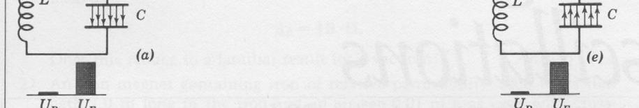
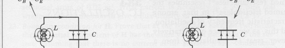
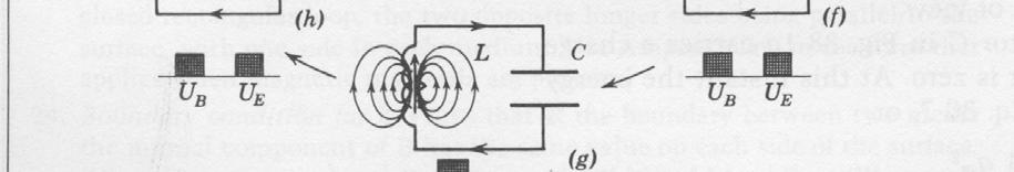
23 Concept Question: Expt. 8 In today s lab the battery turns on and off. Which circuit diagram is most representative of our circuit? Load lab while waiting
24 Concept Question Questions: Undriven Circuits it 24
25 Concept Question: LC Circuit The plot shows the charge on a capacitor (black curve) 0.5Q 0 and the current through it 0.0Q (red curve) after you turn 0 off the power supply. If you put a core into the inductor what will happen to the time T Lag? Capacitor Charge on 1. It will increase 2. It will decrease 3. It will stay the same 4. I don t know 1.0Q 0 1.0I 0 T Current lag Charge 0.5I 0 0.0I 0-0.5Q 0-0.5I 0-1.0Q 0-1.0I Time (ms) Current throu ugh Capacito or
26 Concept Question: LC Circuit If you increase the 0.5Q resistance in the circuit 0 what will happen to rate 0.0Q 0 of decay of the pictured amplitudes? Capacitor Charge on 1.0Q 0 1.0I 0 T Current lag Charge 0.5I 0 0.0I 0-0.5Q 0-0.5I 0-1.0Q 0-1.0I Time (ms) 1. It will increase (decay more rapidly) 2. It will decrease (decay less rapidly) 3. It will stay the same 4. I don t know Current throu ugh Capacito or 26
27 MIT OpenCourseWare SC Physics II: Electricity and Magnetism Fall 2010 For information about citing these materials or our Terms of Use, visit:
Module 25: Outline Resonance & Resonance Driven & LRC Circuits Circuits 2
 Module 25: Driven RLC Circuits 1 Module 25: Outline Resonance & Driven LRC Circuits 2 Driven Oscillations: Resonance 3 Mass on a Spring: Simple Harmonic Motion A Second Look 4 Mass on a Spring (1) (2)
Inductance, RL and RLC Circuits
 Inductance, RL and RLC Circuits Inductance Temporarily storage of energy by the magnetic field When the switch is closed, the current does not immediately reach its maximum value. Faraday s law of electromagnetic
Lecture 39. PHYC 161 Fall 2016
 Lecture 39 PHYC 161 Fall 016 Announcements DO THE ONLINE COURSE EVALUATIONS - response so far is < 8 % Magnetic field energy A resistor is a device in which energy is irrecoverably dissipated. By contrast,
Handout 10: Inductance. Self-Inductance and inductors
 1 Handout 10: Inductance Self-Inductance and inductors In Fig. 1, electric current is present in an isolate circuit, setting up magnetic field that causes a magnetic flux through the circuit itself. This
Lecture 35: FRI 17 APR Electrical Oscillations, LC Circuits, Alternating Current I
 Physics 3 Jonathan Dowling Lecture 35: FRI 7 APR Electrical Oscillations, LC Circuits, Alternating Current I Nikolai Tesla What are we going to learn? A road map Electric charge è Electric force on other
Inductance, Inductors, RL Circuits & RC Circuits, LC, and RLC Circuits
 Inductance, Inductors, RL Circuits & RC Circuits, LC, and RLC Circuits Self-inductance A time-varying current in a circuit produces an induced emf opposing the emf that initially set up the timevarying
Active Figure 32.3 (SLIDESHOW MODE ONLY)
") RL Circuit, Analysis An RL circuit contains an inductor and a resistor When the switch is closed (at time t = 0), the current begins to increase At the same time, a back emf is induced in the inductor
RL Circuit, Analysis An RL circuit contains an inductor and a resistor When the switch is closed (at time t = 0), the current begins to increase At the same time, a back emf is induced in the inductor
Inductance, RL Circuits, LC Circuits, RLC Circuits
 Inductance, R Circuits, C Circuits, RC Circuits Inductance What happens when we close the switch? The current flows What does the current look like as a function of time? Does it look like this? I t Inductance
Physics 4B Chapter 31: Electromagnetic Oscillations and Alternating Current
 Physics 4B Chapter 31: Electromagnetic Oscillations and Alternating Current People of mediocre ability sometimes achieve outstanding success because they don't know when to quit. Most men succeed because
C R. Consider from point of view of energy! Consider the RC and LC series circuits shown:
 ircuits onsider the R and series circuits shown: ++++ ---- R ++++ ---- Suppose that the circuits are formed at t with the capacitor charged to value. There is a qualitative difference in the time development
Electromagnetic Oscillations and Alternating Current. 1. Electromagnetic oscillations and LC circuit 2. Alternating Current 3.
 Electromagnetic Oscillations and Alternating Current 1. Electromagnetic oscillations and LC circuit 2. Alternating Current 3. RLC circuit in AC 1 RL and RC circuits RL RC Charging Discharging I = emf R
Yell if you have any questions
 Class 31: Outline Hour 1: Concept Review / Overview PRS Questions possible exam questions Hour : Sample Exam Yell if you have any questions P31 1 Exam 3 Topics Faraday s Law Self Inductance Energy Stored
AC Circuits III. Physics 2415 Lecture 24. Michael Fowler, UVa
 AC Circuits III Physics 415 Lecture 4 Michael Fowler, UVa Today s Topics LC circuits: analogy with mass on spring LCR circuits: damped oscillations LCR circuits with ac source: driven pendulum, resonance.
Physics 11b Lecture #15
 Physics 11b ecture #15 and ircuits A ircuits S&J hapter 3 & 33 Administravia Midterm # is Thursday If you can t take midterm, you MUST let us (me, arol and Shaun) know in writing before Wednesday noon
Chapter 32. Inductance
 Chapter 32 Inductance Joseph Henry 1797 1878 American physicist First director of the Smithsonian Improved design of electromagnet Constructed one of the first motors Discovered self-inductance Unit of
PES 1120 Spring 2014, Spendier Lecture 35/Page 1
 PES 0 Spring 04, Spendier Lecture 35/Page Today: chapter 3 - LC circuits We have explored the basic physics of electric and magnetic fields and how energy can be stored in capacitors and inductors. We
EM Oscillations. David J. Starling Penn State Hazleton PHYS 212
 I ve got an oscillating fan at my house. The fan goes back and forth. It looks like the fan is saying No. So I like to ask it questions that a fan would say no to. Do you keep my hair in place? Do you
Self-inductance A time-varying current in a circuit produces an induced emf opposing the emf that initially set up the time-varying current.
 Inductance Self-inductance A time-varying current in a circuit produces an induced emf opposing the emf that initially set up the time-varying current. Basis of the electrical circuit element called an
P441 Analytical Mechanics - I. RLC Circuits. c Alex R. Dzierba. In this note we discuss electrical oscillating circuits: undamped, damped and driven.
 Lecture 10 Monday - September 19, 005 Written or last updated: September 19, 005 P441 Analytical Mechanics - I RLC Circuits c Alex R. Dzierba Introduction In this note we discuss electrical oscillating
Chapter 30 Self Inductance, Inductors & DC Circuits Revisited
 Chapter 30 Self Inductance, Inductors & DC Circuits Revisited Self-Inductance and Inductors Self inductance determines the magnetic flux in a circuit due to the circuit s own current. B = LI Every circuit
Exam 3 Topics. Displacement Current Poynting Vector. Faraday s Law Self Inductance. Circuits. Energy Stored in Inductor/Magnetic Field
 Exam 3 Topics Faraday s Law Self Inductance Energy Stored in Inductor/Magnetic Field Circuits LR Circuits Undriven (R)LC Circuits Driven RLC Circuits Displacement Current Poynting Vector NO: B Materials,
Physics for Scientists & Engineers 2
 Electromagnetic Oscillations Physics for Scientists & Engineers Spring Semester 005 Lecture 8! We have been working with circuits that have a constant current a current that increases to a constant current
Lecture 4: R-L-C Circuits and Resonant Circuits
 Lecture 4: R-L-C Circuits and Resonant Circuits RLC series circuit: What's V R? Simplest way to solve for V is to use voltage divider equation in complex notation: V X L X C V R = in R R + X C + X L L
Driven RLC Circuits Challenge Problem Solutions
 Driven LC Circuits Challenge Problem Solutions Problem : Using the same circuit as in problem 6, only this time leaving the function generator on and driving below resonance, which in the following pairs
Coupled Electrical Oscillators Physics Advanced Physics Lab - Summer 2018 Don Heiman, Northeastern University, 5/24/2018
 Coupled Electrical Oscillators Physics 3600 - Advanced Physics Lab - Summer 08 Don Heiman, Northeastern University, 5/4/08 I. INTRODUCTION The objectives of this experiment are: () explore the properties
Slide 1 / 26. Inductance by Bryan Pflueger
 Slide 1 / 26 Inductance 2011 by Bryan Pflueger Slide 2 / 26 Mutual Inductance If two coils of wire are placed near each other and have a current passing through them, they will each induce an emf on one
R-L-C Circuits and Resonant Circuits
 P517/617 Lec4, P1 R-L-C Circuits and Resonant Circuits Consider the following RLC series circuit What's R? Simplest way to solve for is to use voltage divider equation in complex notation. X L X C in 0
11 Chapter. Inductance and Magnetic Energy
 11 Chapter Inductance and Magnetic Energy 11.1 Mutual Inductance... 11-3 Example 11.1 Mutual Inductance of Two Concentric Co-planar Loops... 11-5 11.2 Self-Inductance... 11-6 Example 11.2 Self-Inductance
Simple Harmonic Motion Concept Questions
 Simple Harmonic Motion Concept Questions Question 1 Which of the following functions x(t) has a second derivative which is proportional to the negative of the function d x! " x? dt 1 1. x( t ) = at. x(
Chapter 32. Inductance
 Chapter 32 Inductance Inductance Self-inductance A time-varying current in a circuit produces an induced emf opposing the emf that initially set up the time-varying current. Basis of the electrical circuit
Electric Circuit Theory
 Electric Circuit Theory Nam Ki Min nkmin@korea.ac.kr 010-9419-2320 Chapter 8 Natural and Step Responses of RLC Circuits Nam Ki Min nkmin@korea.ac.kr 010-9419-2320 8.1 Introduction to the Natural Response
2.4 Models of Oscillation
 2.4 Models of Oscillation In this section we give three examples of oscillating physical systems that can be modeled by the harmonic oscillator equation. Such models are ubiquitous in physics, but are
Module 22 and 23: Section 11.1 through Section 11.4 Module 24: Section 11.4 through Section Table of Contents
 Module and 3: Section 11.1 through Section 11.4 Module 4: Section 11.4 through Section 11.13 1 Table of Contents Inductance and Magnetic Energy... 11-3 11.1 Mutual Inductance... 11-3 Example 11.1 Mutual
Chapter 30 Inductance
 Chapter 30 Inductance In this chapter we investigate the properties of an inductor in a circuit. There are two kinds of inductance mutual inductance and self-inductance. An inductor is formed by taken
2.4 Harmonic Oscillator Models
 2.4 Harmonic Oscillator Models In this section we give three important examples from physics of harmonic oscillator models. Such models are ubiquitous in physics, but are also used in chemistry, biology,
Physics 2112 Unit 19
 Physics 11 Unit 19 Today s oncepts: A) L circuits and Oscillation Frequency B) Energy ) RL circuits and Damping Electricity & Magnetism Lecture 19, Slide 1 Your omments differential equations killing me.
Chapter 31: RLC Circuits. PHY2049: Chapter 31 1
 hapter 31: RL ircuits PHY049: hapter 31 1 L Oscillations onservation of energy Topics Damped oscillations in RL circuits Energy loss A current RMS quantities Forced oscillations Resistance, reactance,
ELECTROMAGNETIC INDUCTION AND FARADAY S LAW
 ELECTROMAGNETIC INDUCTION AND FARADAY S LAW Magnetic Flux The emf is actually induced by a change in the quantity called the magnetic flux rather than simply py by a change in the magnetic field Magnetic
Solutions to these tests are available online in some places (but not all explanations are good)...
...") The Physics GRE Sample test put out by ETS https://www.ets.org/s/gre/pdf/practice_book_physics.pdf OSU physics website has lots of tips, and 4 additional tests http://www.physics.ohiostate.edu/undergrad/ugs_gre.php
The Physics GRE Sample test put out by ETS https://www.ets.org/s/gre/pdf/practice_book_physics.pdf OSU physics website has lots of tips, and 4 additional tests http://www.physics.ohiostate.edu/undergrad/ugs_gre.php
MASSACHUSETTS INSTITUTE OF TECHNOLOGY Department of Physics 8.02 Spring 2003 Experiment 17: RLC Circuit (modified 4/15/2003) OBJECTIVES
 OBJECTIVES") MASSACHUSETTS INSTITUTE OF TECHNOLOGY Department of Physics 8. Spring 3 Experiment 7: R Circuit (modified 4/5/3) OBJECTIVES. To observe electrical oscillations, measure their frequencies, and verify energy
MASSACHUSETTS INSTITUTE OF TECHNOLOGY Department of Physics 8. Spring 3 Experiment 7: R Circuit (modified 4/5/3) OBJECTIVES. To observe electrical oscillations, measure their frequencies, and verify energy
Source-Free RC Circuit
 First Order Circuits Source-Free RC Circuit Initial charge on capacitor q = Cv(0) so that voltage at time 0 is v(0). What is v(t)? Prof Carruthers (ECE @ BU) EK307 Notes Summer 2018 150 / 264 First Order
APPLICATIONS OF SECOND-ORDER DIFFERENTIAL EQUATIONS
 APPLICATIONS OF SECOND-ORDER DIFFERENTIAL EQUATIONS Second-order linear differential equations have a variety of applications in science and engineering. In this section we explore two of them: the vibration
Physics 240 Fall 2005: Exam #3. Please print your name: Please list your discussion section number: Please list your discussion instructor:
 Physics 240 Fall 2005: Exam #3 Please print your name: Please list your discussion section number: Please list your discussion instructor: Form #1 Instructions 1. Fill in your name above 2. This will be
Name:... Section:... Physics 208 Quiz 8. April 11, 2008; due April 18, 2008
 Name:... Section:... Problem 1 (6 Points) Physics 8 Quiz 8 April 11, 8; due April 18, 8 Consider the AC circuit consisting of an AC voltage in series with a coil of self-inductance,, and a capacitor of
Honors Differential Equations
 MIT OpenCourseWare http://ocw.mit.edu 18.034 Honors Differential Equations Spring 009 For information about citing these materials or our Terms of Use, visit: http://ocw.mit.edu/terms. LECTURE 7. MECHANICAL
Chapter 30 Inductance and Electromagnetic Oscillations
 Chapter 30 Inductance and Electromagnetic Oscillations Units of Chapter 30 30.1 Mutual Inductance: 1 30.2 Self-Inductance: 2, 3, & 4 30.3 Energy Stored in a Magnetic Field: 5, 6, & 7 30.4 LR Circuit: 8,
Chapter 33. Alternating Current Circuits
 Chapter 33 Alternating Current Circuits 1 Capacitor Resistor + Q = C V = I R R I + + Inductance d I Vab = L dt AC power source The AC power source provides an alternative voltage, Notation - Lower case
Electromagnetic Induction (Chapters 31-32)
") Electromagnetic Induction (Chapters 31-3) The laws of emf induction: Faraday s and Lenz s laws Inductance Mutual inductance M Self inductance L. Inductors Magnetic field energy Simple inductive circuits
Electromagnetic Induction (Chapters 31-3) The laws of emf induction: Faraday s and Lenz s laws Inductance Mutual inductance M Self inductance L. Inductors Magnetic field energy Simple inductive circuits
First and Second Order Circuits. Claudio Talarico, Gonzaga University Spring 2015
 First and Second Order Circuits Claudio Talarico, Gonzaga University Spring 2015 Capacitors and Inductors intuition: bucket of charge q = Cv i = C dv dt Resist change of voltage DC open circuit Store voltage
Oscillations. Tacoma Narrow Bridge: Example of Torsional Oscillation
 Oscillations Mechanical Mass-spring system nd order differential eq. Energy tossing between mass (kinetic energy) and spring (potential energy) Effect of friction, critical damping (shock absorber) Simple
ELECTROMAGNETIC OSCILLATIONS AND ALTERNATING CURRENT
 Chapter 31: ELECTROMAGNETIC OSCILLATIONS AND ALTERNATING CURRENT 1 A charged capacitor and an inductor are connected in series At time t = 0 the current is zero, but the capacitor is charged If T is the
MODULE I. Transient Response:
 Transient Response: MODULE I The Transient Response (also known as the Natural Response) is the way the circuit responds to energies stored in storage elements, such as capacitors and inductors. If a capacitor
Last time. Ampere's Law Faraday s law
 Last time Ampere's Law Faraday s law 1 Faraday s Law of Induction (More Quantitative) The magnitude of the induced EMF in conducting loop is equal to the rate at which the magnetic flux through the surface
Mechanical Energy and Simple Harmonic Oscillator
 Mechanical Energy and Simple Harmonic Oscillator Simple Harmonic Motion Hooke s Law Define system, choose coordinate system. Draw free-body diagram. Hooke s Law! F spring =!kx ˆi! kx = d x m dt Checkpoint
Circuits with Capacitor and Inductor
 Circuits with Capacitor and Inductor We have discussed so far circuits only with resistors. While analyzing it, we came across with the set of algebraic equations. Hereafter we will analyze circuits with
RLC Circuits. 1 Introduction. 1.1 Undriven Systems. 1.2 Driven Systems
 RLC Circuits Equipment: Capstone, 850 interface, RLC circuit board, 4 leads (91 cm), 3 voltage sensors, Fluke mulitmeter, and BNC connector on one end and banana plugs on the other Reading: Review AC circuits
Toolbox: Electrical Systems Dynamics
 Toolbox: Electrical Systems Dynamics Dr. John C. Wright MIT - PSFC 05 OCT 2010 Introduction Outline Outline AC and DC power transmission Basic electric circuits Electricity and the grid Image removed due
AC Circuits Homework Set
 Problem 1. In an oscillating LC circuit in which C=4.0 μf, the maximum potential difference across the capacitor during the oscillations is 1.50 V and the maximum current through the inductor is 50.0 ma.
RLC Circuit (3) We can then write the differential equation for charge on the capacitor. The solution of this differential equation is
 We can then write the differential equation for charge on the capacitor. The solution of this differential equation is") RLC Circuit (3) We can then write the differential equation for charge on the capacitor The solution of this differential equation is (damped harmonic oscillation!), where 25 RLC Circuit (4) If we charge
RLC Circuit (3) We can then write the differential equation for charge on the capacitor The solution of this differential equation is (damped harmonic oscillation!), where 25 RLC Circuit (4) If we charge
Concept Question: Capacitors
 oncept Question: apacitors Three identical capacitors are connected to a battery. The battery is then disconnected. A How do the charge on A, B & compare before and after the battery B is removed? BEFOE;
2.004 Dynamics and Control II Spring 2008
 MIT OpenCourseWare http://ocwmitedu 00 Dynamics and Control II Spring 00 For information about citing these materials or our Terms of Use, visit: http://ocwmitedu/terms Massachusetts Institute of Technology
Handout 11: AC circuit. AC generator
 Handout : AC circuit AC generator Figure compares the voltage across the directcurrent (DC) generator and that across the alternatingcurrent (AC) generator For DC generator, the voltage is constant For
SCHOOL OF MATHEMATICS MATHEMATICS FOR PART I ENGINEERING. Self-paced Course
 SCHOOL OF MATHEMATICS MATHEMATICS FOR PART I ENGINEERING Self-paced Course MODULE 26 APPLICATIONS TO ELECTRICAL CIRCUITS Module Topics 1. Complex numbers and alternating currents 2. Complex impedance 3.
The Harmonic Oscillator
 The Harmonic Oscillator Math 4: Ordinary Differential Equations Chris Meyer May 3, 008 Introduction The harmonic oscillator is a common model used in physics because of the wide range of problems it can
Final Exam Physics 7b Section 2 Fall 2004 R Packard. Section Number:
 Final Exam Physics 7b Section 2 Fall 2004 R Packard Name: SID: Section Number: The relative weight of each problem is stated next to the problem. Work the easier ones first. Define physical quantities
RLC Series Circuit. We can define effective resistances for capacitors and inductors: 1 = Capacitive reactance:
 RLC Series Circuit In this exercise you will investigate the effects of changing inductance, capacitance, resistance, and frequency on an RLC series AC circuit. We can define effective resistances for
AP Physics C Mechanics Objectives
 AP Physics C Mechanics Objectives I. KINEMATICS A. Motion in One Dimension 1. The relationships among position, velocity and acceleration a. Given a graph of position vs. time, identify or sketch a graph
AC Circuits and Electromagnetic Waves
 AC Circuits and Electromagnetic Waves Physics 102 Lecture 5 7 March 2002 MIDTERM Wednesday, March 13, 7:30-9:00 pm, this room Material: through next week AC circuits Next week: no lecture, no labs, no
Chapter 31 Electromagnetic Oscillations and Alternating Current LC Oscillations, Qualitatively
 Chapter 3 Electromagnetic Oscillations and Alternating Current LC Oscillations, Qualitatively In the LC circuit the charge, current, and potential difference vary sinusoidally (with period T and angular
INDUCTANCE Self Inductance
 NDUTANE 3. Self nductance onsider the circuit shown in the Figure. When the switch is closed the current, and so the magnetic field, through the circuit increases from zero to a specific value. The increasing
Physics 115. AC: RL vs RC circuits Phase relationships RLC circuits. General Physics II. Session 33
 Session 33 Physics 115 General Physics II AC: RL vs RC circuits Phase relationships RLC circuits R. J. Wilkes Email: phy115a@u.washington.edu Home page: http://courses.washington.edu/phy115a/ 6/2/14 1
Inductance. Slide 2 / 26. Slide 1 / 26. Slide 4 / 26. Slide 3 / 26. Slide 6 / 26. Slide 5 / 26. Mutual Inductance. Mutual Inductance.
 Slide 1 / 26 Inductance 2011 by Bryan Pflueger Slide 2 / 26 Mutual Inductance If two coils of wire are placed near each other and have a current passing through them, they will each induce an emf on one
ENGR 2405 Chapter 8. Second Order Circuits
 ENGR 2405 Chapter 8 Second Order Circuits Overview The previous chapter introduced the concept of first order circuits. This chapter will expand on that with second order circuits: those that need a second
NAME: PHYSICS 6B SPRING 2011 FINAL EXAM ( VERSION A )
") NAME: PHYSCS 6B SPRNG 2011 FNAL EXAM ( VERSON A ) Choose the best answer for each of the following multiple-choice questions. There is only one answer for each. Questions 1-2 are based on the following
NAME: PHYSCS 6B SPRNG 2011 FNAL EXAM ( VERSON A ) Choose the best answer for each of the following multiple-choice questions. There is only one answer for each. Questions 1-2 are based on the following
Chapter 30 INDUCTANCE. Copyright 2012 Pearson Education Inc.
 Chapter 30 INDUCTANCE Goals for Chapter 30 To learn how current in one coil can induce an emf in another unconnected coil To relate the induced emf to the rate of change of the current To calculate the
Wave Phenomena Physics 15c
 Wave Phenomena Physics 15c Lecture Harmonic Oscillators (H&L Sections 1.4 1.6, Chapter 3) Administravia! Problem Set #1! Due on Thursday next week! Lab schedule has been set! See Course Web " Laboratory
EE 242 EXPERIMENT 8: CHARACTERISTIC OF PARALLEL RLC CIRCUIT BY USING PULSE EXCITATION 1
 EE 242 EXPERIMENT 8: CHARACTERISTIC OF PARALLEL RLC CIRCUIT BY USING PULSE EXCITATION 1 PURPOSE: To experimentally study the behavior of a parallel RLC circuit by using pulse excitation and to verify that
General Response of Second Order System
 General Response of Second Order System Slide 1 Learning Objectives Learn to analyze a general second order system and to obtain the general solution Identify the over-damped, under-damped, and critically
Chapter 30. Inductance
 Chapter 30 Inductance Self Inductance When a time dependent current passes through a coil, a changing magnetic flux is produced inside the coil and this in turn induces an emf in that same coil. This induced
Alternating Current Circuits. Home Work Solutions
 Chapter 21 Alternating Current Circuits. Home Work s 21.1 Problem 21.11 What is the time constant of the circuit in Figure (21.19). 10 Ω 10 Ω 5.0 Ω 2.0µF 2.0µF 2.0µF 3.0µF Figure 21.19: Given: The circuit
1 2 U CV. K dq I dt J nqv d J V IR P VI
 o 5 o T C T F 3 9 T K T o C 73.5 L L T V VT Q mct nct Q F V ml F V dq A H k TH TC L pv nrt 3 Ktr nrt 3 CV R ideal monatomic gas 5 CV R ideal diatomic gas w/o vibration V W pdv V U Q W W Q e Q Q e Carnot
Response of Second-Order Systems
 Unit 3 Response of SecondOrder Systems In this unit, we consider the natural and step responses of simple series and parallel circuits containing inductors, capacitors and resistors. The equations which
Chapter 28. Direct Current Circuits
 Chapter 28 Direct Current Circuits Circuit Analysis Simple electric circuits may contain batteries, resistors, and capacitors in various combinations. For some circuits, analysis may consist of combining
University of California, Berkeley Physics H7B Spring 1999 (Strovink) SOLUTION TO PROBLEM SET 11 Solutions by P. Pebler
 SOLUTION TO PROBLEM SET 11 Solutions by P. Pebler") University of California Berkeley Physics H7B Spring 999 (Strovink) SOLUTION TO PROBLEM SET Solutions by P. Pebler Purcell 7.2 A solenoid of radius a and length b is located inside a longer solenoid of
University of California Berkeley Physics H7B Spring 999 (Strovink) SOLUTION TO PROBLEM SET Solutions by P. Pebler Purcell 7.2 A solenoid of radius a and length b is located inside a longer solenoid of
Oscillations and Waves
 Oscillations and Waves Somnath Bharadwaj and S. Pratik Khastgir Department of Physics and Meteorology IIT Kharagpur Module : Oscillations Lecture : Oscillations Oscillations are ubiquitous. It would be
Part 4: Electromagnetism. 4.1: Induction. A. Faraday's Law. The magnetic flux through a loop of wire is
 1 Part 4: Electromagnetism 4.1: Induction A. Faraday's Law The magnetic flux through a loop of wire is Φ = BA cos θ B A B = magnetic field penetrating loop [T] A = area of loop [m 2 ] = angle between field
Chapter 5 Oscillatory Motion
 Chapter 5 Oscillatory Motion Simple Harmonic Motion An object moves with simple harmonic motion whenever its acceleration is proportional to its displacement from some equilibrium position and is oppositely
Excitation Optimization of a Standard LRC Circuit with Impulsive Forces Selected via Simulated Annealing
 Hamline University DigitalCommons@Hamline Departmental Honors Projects College of Liberal Arts Spring 2013 Excitation Optimization of a Standard LRC Circuit with Impulsive Forces Selected via Simulated
Yell if you have any questions
 Class 36: Outline Hour 1: Concept Review / Overview PRS Questions Possible Exam Questions Hour : Sample Exam Yell if you have any questions P36-1 efore Starting All of your grades should now be posted
Mixing Problems. Solution of concentration c 1 grams/liter flows in at a rate of r 1 liters/minute. Figure 1.7.1: A mixing problem.
 page 57 1.7 Modeling Problems Using First-Order Linear Differential Equations 57 For Problems 33 38, use a differential equation solver to determine the solution to each of the initial-value problems and
Chapter 13 Lecture. Essential University Physics Richard Wolfson 2 nd Edition. Oscillatory Motion Pearson Education, Inc.
 Chapter 13 Lecture Essential University Physics Richard Wolfson nd Edition Oscillatory Motion Slide 13-1 In this lecture you ll learn To describe the conditions under which oscillatory motion occurs To
A capacitor is a device that stores electric charge (memory devices). A capacitor is a device that stores energy E = Q2 2C = CV 2
. A capacitor is a device that stores energy E = Q2 2C = CV 2") Capacitance: Lecture 2: Resistors and Capacitors Capacitance (C) is defined as the ratio of charge (Q) to voltage (V) on an object: C = Q/V = Coulombs/Volt = Farad Capacitance of an object depends on geometry
Capacitance: Lecture 2: Resistors and Capacitors Capacitance (C) is defined as the ratio of charge (Q) to voltage (V) on an object: C = Q/V = Coulombs/Volt = Farad Capacitance of an object depends on geometry
Wave Phenomena Physics 15c
 Wave Phenomena Physics 15c Lecture Harmonic Oscillators (H&L Sections 1.4 1.6, Chapter 3) Administravia! Problem Set #1! Due on Thursday next week! Lab schedule has been set! See Course Web " Laboratory
Forced Mechanical Vibrations
 Forced Mechanical Vibrations Today we use methods for solving nonhomogeneous second order linear differential equations to study the behavior of mechanical systems.. Forcing: Transient and Steady State
1 Phasors and Alternating Currents
 Physics 4 Chapter : Alternating Current 0/5 Phasors and Alternating Currents alternating current: current that varies sinusoidally with time ac source: any device that supplies a sinusoidally varying potential
Oscillations. Simple Harmonic Motion of a Mass on a Spring The equation of motion for a mass m is attached to a spring of constant k is
 Dr. Alain Brizard College Physics I (PY 10) Oscillations Textbook Reference: Chapter 14 sections 1-8. Simple Harmonic Motion of a Mass on a Spring The equation of motion for a mass m is attached to a spring
PHYS 241 EXAM #2 November 9, 2006
 1. ( 5 points) A resistance R and a 3.9 H inductance are in series across a 60 Hz AC voltage. The voltage across the resistor is 23 V and the voltage across the inductor is 35 V. Assume that all voltages
Laboratory I: Impedance
 Physics 331, Fall 2008 Lab I - Handout 1 Laboratory I: Impedance Reading: Simpson Chapter 1 (if necessary) & Chapter 2 (particularly 2.9-2.13) 1 Introduction In this first lab we review the properties
Simple Harmonic Oscillator Challenge Problems
 Simple Harmonic Oscillator Challenge Problems Problem 1: Dimensional Analysis, Estimation and Concepts Imagine that one drilled a hole with smooth sides straight through the center of the earth, of radius
Yell if you have any questions
 Class 36: Outline Hour 1: Concept Review / Overview PRS Questions Possible Exam Questions Hour : Sample Exam Yell if you have any questions P36-1 Before Starting All of your grades should now be posted