ECE2262 Electric Circuits. Chapter 6: Capacitance and Inductance
|
|
|
- Sibyl McGee
- 6 years ago
- Views:
Transcription
1 ECE2262 Electric Circuits Chapter 6: Capacitance and Inductance Capacitors Inductors Capacitor and Inductor Combinations Op-Amp Integrator and Op-Amp Differentiator 1
2 CAPACITANCE AND INDUCTANCE Introduces two passive, energy storing devices: Capacitors and Inductors LEARNING GOALS CAPACITORS Store energy in their electric field (electrostatic energy) Model as circuit element INDUCTORS Store energy in their magnetic field Model as circuit element CAPACITOR AND INDUCTOR COMBINATIONS Series/parallel combinations of elements RC OP-AMP CIRCUITS Integration and differentiation circuits 2

3 6.1 Capacitors Electronic Symbol: 3
 is called the dielectric Charge separation in a parallel-plate capacitor causes an internal electric field.")
4 A capacitor consists of two conductors separated by a non-conductive region. The non-conductive region (orange) is called the dielectric Charge separation in a parallel-plate capacitor causes an internal electric field. A dielectric reduces the electric field and increases the capacitance. Because the conductors (or plates) are close together, the opposite charges on the conductors attract one another due to their electric fields, allowing the capacitor to store more charge for a given voltage than if the conductors were separated, giving the capacitor a large capacitance. 4
5 In the hydraulic analogy, a capacitor is analogous to a rubber membrane sealed inside a pipe. This animation illustrates a membrane being repeatedly stretched and un-stretched by the flow of water, which is analogous to a capacitor being repeatedly charged and discharged by the flow of charge In the hydraulic analogy, charge carriers flowing through a wire are analogous to water flowing through a pipe. A capacitor is like a rubber membrane sealed inside a pipe. Water molecules cannot pass through the membrane, but some water can move by stretching the membrane. The analogy clarifies a few aspects of capacitors. The more a capacitor is charged, the larger its voltage drop; i.e., the more it "pushes back" against the charging current. This is analogous to the fact that the more a membrane is stretched, the more it pushes back on the water. 5
6 The capacitance describes how much charge can be stored on one plate of a capacitor for a given "push" (voltage drop). A very stretchy, flexible membrane corresponds to a higher capacitance than a stiff membrane. A charged-up capacitor is storing potential energy, analogously to a stretched membrane. C : Capacitance of 1 Farad = 1 Coulomb of charge on each conductor causes a voltage of 1 Volt across the device. 1C = 1F!1V! Q = CV 6
7 Current! Voltage Relations C! A d The charge on the capacitor is proportional to the voltage across q = C v C : Capacitance in Farads (F) - common values µf, pf( pico = 10!12 ) 7
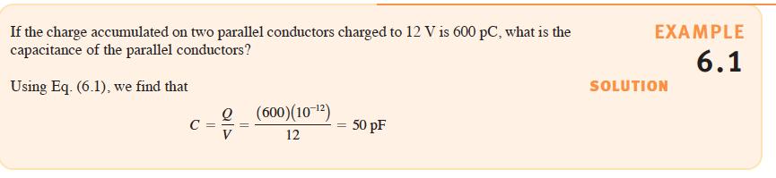
8 Example 8
9 Voltage! Current Relation Since q = C v and i = dq dt then we have i = d( C v) dt = C d v dt. ( ) = C d v ( t ) i t dt 9
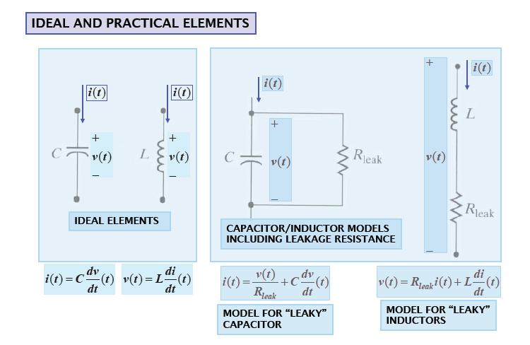
10 ( ) = C dv( t) i t dt In circuits with with time-independent voltage ( DC circuits) the capacitor behaves as open circuit (capacitor blocks dc). In analyzing a circuit containing dc voltage sources and capacitors, we can replace the capacitors with an open circuit and calculate voltages and currents in the circuit using our many analysis tools. 10


11 Example C = 5µF i = C d v dt 11
12 Current! Voltage Relation i( t) v( t) Since i t ( ) = C d v( t) dt then ( ) t i (! )d! t " = C d v! t d! t 0 " = C dv! t 0 ( ) d! " = = C v t t 0 { ( )! v( t 0 )} v( t ) = v t 0 ( )+ 1 t C " i (! )d! t 0 t! t 0 12
13 v( t ) = v t 0 ( )+ 1 t C " i (! )d! t 0 for any time t! t 0 v t 0 ( ) - initial value (initial state) representing the voltage due to the charge that accumulates on the capacitor from the past to t = t 0. 13
14 Example Suppose that C = 1F and v 0 Determine v( t). ( ) = 1V. The current source i( t) = e!t/2, t > 0. i( t) v( t) v( t) = v( 0) + 1 t C i! " ( )d! t = 1+ # e!" /2 d" = 1! 2 e 0 0 {!" /2} t 0 = 1+ 2{ 1! e!t/2 } for t! 0! v( t) = # % $ &% 1+ 2{ 1! e!t/2 } t > 0 1 t " 0 14
15 v( t) = # % $ &% 1+ 2{ 1! e!t/2 } t > 0 1 t " 0 Note: i( t) has a jump, but v( t) is continuous! 15
16 Power Delivered to Capacitor Since i t ( ) = C d v( t) dt or v( t) = v( t 0 ) + 1 t C i! t 0 ( )d! " then we have p( t) = v( t)i( t) = C v t ( ) d v( t) dt = i t # $ % ( ) v( t 0 ) + 1 t C i! " t 0 ( )d! & ' ( Note: If v( t) would have a jump then 16 d v( t) =! and p( t) =! but this is dt impossible. Hence, the voltage response of a capacitor must be always continuous!
17 If we encounter circuits containing switches then the idea of continuity of voltage for a capacitor tells us that the voltage across the capacitor just after a switch moves is the same as the voltage across the capacitor just before that switch moves. 17
18 Energy Stored in the Capacitor Electric Field p( t) = C v( t) d v( t) = C 1 dt 2 = d! 1 dt 2 C $ " ( v2 t) % # & d v 2 ( t) dt! d dt ( t) { v 2 } = 2v t ( ) d dt { v( t) } w( t) = 1 2 C ( v2 t ) (J) Since q( t) = Cv( t) then also w( t) = 1 2 q 2 t ( ) C. 18
19 Example An uncharged capacitor 2 F is driven by a rectangular current pulse. i( t) 1 t 1 (a)the capacitor voltage v( t) = v( 0) t " i (! )d! = t # 1( 0! "! 1)d" = 0! " # t / 2 0! t! 1 1/ 2 t > 1. (b) The capacitor power: p( t) = i( t)v( t) =! " # t / 2 0! t! 1 0 else. (c) The capacitor energy: w( t) = 1 2 C ( v2 t) = v 2 ( t) =!# " $# t 2 / 4 0! t! 1 1/ 4 t > 1. 19
20 20
21 Note that power is always positive for the duration of the current pulse, which means that energy is continuously being stored in the capacitor. When the current returns to zero, the stored energy is trapped because the ideal capacitor offers no means for dissipating energy. Thus, a voltage remains on the capacitor after i t ( ) returns to zero. If at some later time an energy-absorbing device (e.g., a flash bulb) is connected across the capacitor, a discharge current will flow from the capacitor and, therefore, the capacitor will supply its stored energy to the device. 21
22 Example ( ) = C dv( t ) i t dt p( t ) = v( t )i( t ) w( t) = 1 ( 2 Cv2 t ) 22
23 Energy is being stored in the capacitor whenever the power is positive (the capacitor acts as a load) Energy is being delivered by the capacitor whenever the power is negative (the capacitor acts as a source) 1 "! p( t)dt = 4µJ - energy stored; # p( t)dt =!4µJ - energy delivered
24 Sinusoidal Input to Capacitor: i t ( ) = C dv( t) dt v( t) = V m cos( 2! f 0 t) i( t) =!CV m 2! f 0 sin( 2! f 0 t) The current i( t) is 90! phase shifted compared to the voltage v( t) The current leads the voltage by 90! 24
25 v( t ) i( t) 25
26 i( t) for f 0 = 1,5,10 Hz The capacitor works as an open circuit for dc voltage ( f 0! 0 ) The capacitor works as a short circuit for high-frequency voltage ( f 0! " ) 26

27 Application RC Low Pass Filter Circuit The reactance of a capacitor varies inversely with frequency, while the value of the resistor remains constant as the frequency changes. At low frequencies the capacitive reactance of the capacitor will be very large compared to the resistive value of the resistor R. This means that the voltage potential, V C across the capacitor will be much larger than the voltage drop, V R developed across the resistor. At high frequencies the reverse is true with V C being small and V R being large due to the change in the capacitive reactance value. 27

28 6.2 Inductors An inductor, also called a coil, choke or reactor, is a passive two terminal electrical component which resists changes in electric current passing through it. It consists of a conductor such as a wire, usually wound into a coil. When a current flows through it, energy is stored temporarily in a magnetic field in the coil. 28

. Inductors have values that typically range from 1!H (10!")
29 When the current flowing through an inductor changes, the time-varying magnetic field induces a voltage in the conductor, according to Faraday s law of electromagnetic induction. An inductor is characterized by its inductance, the ratio of the voltage to the rate of change of current, which has units of henries (H). Inductors have values that typically range from 1!H (10!6 H) to 1 H. 29
30 A capacitor is an integrator of its input current: v( t) = v( t 0 ) + 1 t C i! " t 0 ( )d! L Inductance ( in henrys) An inductor produces a current response that is related to the integral of the voltage applied to its terminals. i( t) = i( t 0 ) + 1 L " t t 0 v (! )d! 30
31 Current! Voltage Relation L ( ) = L di ( t ) v t dt L : Henry = Volt Amp / sec 31
32 32
33 Voltage! Current Relation L i( t) = i( t 0 )+ 1 L " t t 0 v (! )d! Current must be continuous: i( t 0!) = i( t 0 + ) 33
34 Power Delivered to an Inductor p( t) = v( t)i( t) = Li t ( ) di ( t ) dt = v t # $ ( ) i( t 0 ) + 1 % L " t t 0 & v (! )d! ' ( 34
35 Energy Stored in the Inductor Magnetic Field Since p( t) = i t ( ) ( )L di t dt! p t ( ) = 1 2 L ( di2 t) dt! p( t) = d dt! 1 " 2 Li2 t # ( ) $ % & w( t) = 1 ( 2 Li2 t ) (J) 35
36 DC Circuits Consider the case of a dc current flowing through an inductor. Since ( ) = L di( t) v t dt we see that the voltage across the inductor is directly proportional to the time rate of change of the current flowing through the inductor. A dc current does not vary with time, so the voltage across the inductor is zero. We can say that an inductor is a short circuit to dc. 36
37 In analyzing a circuit containing dc sources and inductors, we can replace any inductors with short circuits and calculate voltages and currents in the circuit using our many analysis tools. 37
38 Continuity of i( t)! p( t) = Li( t) di( t) Due to p( t) = Li( t) di( t) we note that an instantaneous change in inductor dt current would require infinite power. Since we don t have any infinite power sources, the current flowing through an inductor cannot change instantaneously. This will be a particularly helpful idea when we encounter circuits containing switches. This idea of continuity of current for an inductor tells us that the current flowing through an inductor just after a switch moves is the same as the current flowing through an inductor just before that switch moves. dt 38
39 Example The independent current source generates zero current for t < 0 and a pulse i t ( ) = 10te!5t A for t > 0 in the following circuit (a) i( t) 39
40 (b) v t ( ) = L di( t) dt = 0.1!10e "5t ( 1" 5t) = e!5t ( 1! 5t), t > 0 At t = 0.2s the voltage changes polarity At t = 0 the voltage has a jump, i.e., the voltage can change instantaneously across the terminals (but not current!) 40
41 (c) p( t) = i( t)v( t) = 10te!5t ( ) { } " { e!5t 1! 5t } = 10te!10t! 50t 2 e!10t W 41
42 (d) w( t) = 1 ( 2 Li2 t) = 1 2! 0.1! ( ) 2 10te"5t = 5t 2 e!10t An increasing energy curve indicates that energy is being stored. Thus, energy is being stored in the time interval 0 to 0.2 sec. This corresponds to the interval when p t ( ) > 0. (the inductor acts as a load) A decreasing energy curve indicates that energy is being extracted. This takes place in the time interval 0.2 to!. This corresponds to the interval when p( t) < 0 (the inductor acts as a source) Energy is max when i( t) is max: w max = 27.07mJ at t = 0.2 sec. 42
43 43
44 (e) Integrals 0.2!! p( t)dt, " p( t)dt p( t)dt = 27.07mJ! 0 The area The area! " p( t)dt = #27.07mJ ! p( t)dt represents the energy stored in the inductor during 0,0.2 0! " p( t)dt represents the energy extracted 0.2 [ ] Energy Stored + Energy Extracted = 0 44
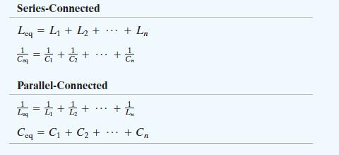
45 Example Find the total energy stored in the circuit (DC circuit) w C = 1 2 Cv2, w L = 1 2 Li2 45
46 DC circuit! capacitors! open circuit, inductors! short circuit We need V c1, V c2 and I L1, I L2 46
47 KCL at A: I L1 + 3! I L2 = 0! I L2 = I L1 + 3 KVL (big loop):!9 + 6I L1 + 3I L2 + 6I L2 = 0! 6I L1 + 9I L2 = 9! I L1 =!1.2A, I L2 = 1.8A 47
48 KVL (first loop):!9 + 6I L1 + V C1 = 0! V C1 = 9! 6I L1 = 16.2 V V C 2 = 6I L2 = 10.8 V 48
49 I L1 =!1.2A, I L2 = 1.8A, V C1 = 16.2V, V C 2 = 10.8V w C1 = 1 2 C V 2 1 C1 = 2.62 mj, w C 2 = 1 2 C V 2 2 C 2 = 2.92 mj w L1 = 1 2 L I 2 1 L1 = 1.44 mj, w L2 = 1 2 L I 2 2 L2 = 6.48 mj The total stored energy = mj 49
50 Sinusoidal Input to Inductor: v t ( ) = L di( t) dt i( t) = I m cos( 2! f 0 t) v( t) =!LI m 2! f 0 sin( 2! f 0 t) The voltage v( t) is 90! phase shifted compared to the current i( t) The current lags the voltage by 90! <----- i( t) crosses zero later 50
51 i( t) v( t ) v( t ) 51
52 v( t) for f 0 = 1,5,10 Hz The inductor works as a short circuit for dc current ( f 0! 0 ) The capacitor works as an open circuit for high-frequency current ( f 0! " ) 52
53 53

54 6.3 Capacitor and Inductor Combinations Series Capacitors v = v v N The charge gained by a plate of any capacitor must come from a plate of an adjacent capacitor, i.e., Q C S = Q C Q C N 1 C S = 1 C C N 54
! ( 30µF) = 240 µc! Q = v 2 C 2! C 2 = Q v 2 = Q v! v 1 = 240µC 4V = 60µF 55")
55 Example Find C 2 C 1 = 30µF v 1 = 8V v = 12V C 2 The charge on both capacitors must be the same! Q = v 1 C 1 = ( 8V )! ( 30µF) = 240 µc! Q = v 2 C 2! C 2 = Q v 2 = Q v! v 1 = 240µC 4V = 60µF 55

56 Example the capacitors have been charged before they were connected Q 1! Q 2! Q 3 (!voltage polarization is different) 1 Equivalent capacitance: = ! C eq = 1µF C eq C 1 C 2 C 3 { } = 31µJ Total energy stored: w == 1 2 C V 2 1 C1 + C 2 V 2 + C V 2 C 2 3 C 3!v + 2! 4!1 = 0! v =!3V! w Ceq == 1 2 C eq v2 = 4.5µJ 56

57 Parallel Capacitors The total stored charge: Q T = Q Q N! vc T = vc vc N C p = C C N 57
58 Example Find each capacitor voltage 400V 20µF + V 1! 40µF 30µF +! + + V V 2 9µF 3 70µF V 4!! 20 40! C 1 = = 60µF C 2 = ( 30! 70) 9 = 30! = = 30µF The equivalent capacitors C 1 and C 2 have the same charge because they are in series with the source. 58
59 400V C 1 = 60µF 20µF + V 1! 40µF 30µF +! + + V V 2 9µF 3 70µF V!! 4 C 2 = 30µF 60! 30 C eq = C 1! C 2 = = 20µF! Q = C eq eq V 1 = 8mC 60µF = 133V V = 8mC 2 30µF = 267V! V = ( 20 )!10"6 ( 400)=8mC charge on( 30µF! 70µF ) = Q eq! charge on 9µF = 8! 267V " 9µF = 5.6mC V 3 = 5.6mC 30µF = 187 V, V 4 = 5.6mC 70µF = 80 V 59
 = L 1 dt di( t) +...+ L N dt ( ) di( t) = L 1 +.")
60 Series Inductors di( t) v( t) = v 1 ( t) v N ( t) = L 1 dt di( t) L N dt ( ) di( t) = L L N dt L S = L L N 60
 + 1 \" ( )d! +...+ 1 t & v (! )d! 0 L 0 N \" ' ( t & v (! )d! L 0 N \" ' (! \" # i( t) = i( 0) + 1 +.")
61 Parallel Inductors i( t) = i 1 ( t) i N ( t) = i 1 ( 0) + 1 t v! L 1 i t # $ % { } + 1 t $ v! L 1 ( ) = i 1 ( 0) i N ( 0) # % " 0 & # ( )d! ' $ i N 0 ( % ( ) + 1 " ( )d! t & v (! )d! 0 L 0 N " ' ( t & v (! )d! L 0 N " ' (! " # i( t) = i( 0) L 1 L N $ % & ( t 0 v (' )d' 61
62 1 L p = 1 L L N 62
63 Example Initial values: i 1 0 The voltage at the terminal v t ( ) = 3A, i 2 ( 0) =!5A ( ) =!30e!5t mv for t! 0 (a) Equivalent inductance: L eq = L 1! L 2 L 1 + L 2 = 60! = 48mH (b) Initial current: i( 0) = i 1 ( 0) + i 2 ( 0) = 3+ (!5) =!2A (current goes up) 63
64 (c) Find i( t): i( t) = i( 0) + 1 t ( ) v! L 0 eq " d! =!2 + 1 t!30e!5# "10!3 48 "10 $ { } d# =!2 + 1!3 0 8 e!5t!1 ( ) =! e!5t A, t! 0 64
65 (d) Find i 1 ( t), i 2 ( t) i 1 ( t) = i 1 ( 0) + 1 t v (! ) L 1 " d! = t "30e "5#!10 "3 60!10 $ { } d# "3 0 = e!5t A, t! 0 i 2 ( t) = i 2 ( 0) + 1 t v (! ) L 2 " d! =! t!30e!5# "10!3 240 "10 $ { } d#!3 0 =! e!5" A, t! 0 65
66 66
67 67

68 6.4 Op-Amp Integrator and Op-Amp Differentiator 68
69 Op-Amp Integrator ( ) = C d v( t) i t dt v s Summing the currents leaving the inverting input: 0! v s ( t) + C d ( 0! v ( t) o ) = 0! dv t o R dt dt v o ( t) =! 1 t RC # v s (" )d" + v o ( ) ( ) =! 1 RC v s ( ) - the initial voltage across the capacitor v o 0 ( t)
70 Op-Amp Differentiator ( ) = C d v( t) i t dt v s Summing the currents leaving the inverting input: ( ( t) ) C d 0! v s dt + 0! v ( t) o R = 0 v o ( t) =!RC dv s t dt 70 ( )
 + v 0 t ( ) =!")
71 More realistic circuit R i v s R i R i C dv 0 dt ( t) + v 0 t ( ) =!RC dv s ( t) 71 dt
72 72
73 SUMMARY 73
74 74
75 In dc steady state, a capacitor looks like an open circuit and an inductor looks like a short circuit. The voltage across a capacitor cannot change instantaneously The current flowing through an inductor cannot change instantaneously.! Example 75
ECE2262 Electric Circuits. Chapter 6: Capacitance and Inductance
 ECE2262 Electric Circuits Chapter 6: Capacitance and Inductance Capacitors Inductors Capacitor and Inductor Combinations 1 CAPACITANCE AND INDUCTANCE Introduces two passive, energy storing devices: Capacitors
Introduction to AC Circuits (Capacitors and Inductors)
") Introduction to AC Circuits (Capacitors and Inductors) Amin Electronics and Electrical Communications Engineering Department (EECE) Cairo University elc.n102.eng@gmail.com http://scholar.cu.edu.eg/refky/
Introduction to AC Circuits (Capacitors and Inductors) Amin Electronics and Electrical Communications Engineering Department (EECE) Cairo University elc.n102.eng@gmail.com http://scholar.cu.edu.eg/refky/
Energy Storage Elements: Capacitors and Inductors
 CHAPTER 6 Energy Storage Elements: Capacitors and Inductors To this point in our study of electronic circuits, time has not been important. The analysis and designs we have performed so far have been static,
ENGR 2405 Chapter 6. Capacitors And Inductors
 ENGR 2405 Chapter 6 Capacitors And Inductors Overview This chapter will introduce two new linear circuit elements: The capacitor The inductor Unlike resistors, these elements do not dissipate energy They
ECE2262 Electric Circuit
 ECE2262 Electric Circuit Chapter 7: FIRST AND SECOND-ORDER RL AND RC CIRCUITS Response to First-Order RL and RC Circuits Response to Second-Order RL and RC Circuits 1 2 7.1. Introduction 3 4 In dc steady
CHAPTER 6. Inductance, Capacitance, and Mutual Inductance
 CHAPTER 6 Inductance, Capacitance, and Mutual Inductance 6.1 The Inductor Inductance is symbolized by the letter L, is measured in henrys (H), and is represented graphically as a coiled wire. The inductor
CIRCUIT ELEMENT: CAPACITOR
 CIRCUIT ELEMENT: CAPACITOR PROF. SIRIPONG POTISUK ELEC 308 Types of Circuit Elements Two broad types of circuit elements Ati Active elements -capable of generating electric energy from nonelectric energy
Pretest ELEA1831 Module 11 Units 1& 2 Inductance & Capacitance
 Pretest ELEA1831 Module 11 Units 1& 2 Inductance & Capacitance 1. What is Faraday s Law? Magnitude of voltage induced in a turn of wire is proportional to the rate of change of flux passing through that
Circuit Analysis-II. Circuit Analysis-II Lecture # 5 Monday 23 rd April, 18
 Circuit Analysis-II Capacitors in AC Circuits Introduction ü The instantaneous capacitor current is equal to the capacitance times the instantaneous rate of change of the voltage across the capacitor.
Driven RLC Circuits Challenge Problem Solutions
 Driven LC Circuits Challenge Problem Solutions Problem : Using the same circuit as in problem 6, only this time leaving the function generator on and driving below resonance, which in the following pairs
Basics of Network Theory (Part-I)
") Basics of Network Theory (Part-I) 1. One coulomb charge is equal to the charge on (a) 6.24 x 10 18 electrons (b) 6.24 x 10 24 electrons (c) 6.24 x 10 18 atoms (d) none of the above 2. The correct relation
Basics of Network Theory (Part-I) 1. One coulomb charge is equal to the charge on (a) 6.24 x 10 18 electrons (b) 6.24 x 10 24 electrons (c) 6.24 x 10 18 atoms (d) none of the above 2. The correct relation
Phys 2025, First Test. September 20, minutes Name:
 Phys 05, First Test. September 0, 011 50 minutes Name: Show all work for maximum credit. Each problem is worth 10 points. Work 10 of the 11 problems. k = 9.0 x 10 9 N m / C ε 0 = 8.85 x 10⁻¹ C / N m e
ELECTRONICS E # 1 FUNDAMENTALS 2/2/2011
 FE Review 1 ELECTRONICS E # 1 FUNDAMENTALS Electric Charge 2 In an electric circuit it there is a conservation of charge. The net electric charge is constant. There are positive and negative charges. Like
Basic Electronics. Introductory Lecture Course for. Technology and Instrumentation in Particle Physics Chicago, Illinois June 9-14, 2011
 Basic Electronics Introductory Lecture Course for Technology and Instrumentation in Particle Physics 2011 Chicago, Illinois June 9-14, 2011 Presented By Gary Drake Argonne National Laboratory drake@anl.gov
AC vs. DC Circuits. Constant voltage circuits. The voltage from an outlet is alternating voltage
 Circuits AC vs. DC Circuits Constant voltage circuits Typically referred to as direct current or DC Computers, logic circuits, and battery operated devices are examples of DC circuits The voltage from
RC, RL, and LCR Circuits
 RC, RL, and LCR Circuits EK307 Lab Note: This is a two week lab. Most students complete part A in week one and part B in week two. Introduction: Inductors and capacitors are energy storage devices. They
EIT Review. Electrical Circuits DC Circuits. Lecturer: Russ Tatro. Presented by Tau Beta Pi The Engineering Honor Society 10/3/2006 1
 EIT Review Electrical Circuits DC Circuits Lecturer: Russ Tatro Presented by Tau Beta Pi The Engineering Honor Society 10/3/2006 1 Session Outline Basic Concepts Basic Laws Methods of Analysis Circuit
ELECTROMAGNETIC OSCILLATIONS AND ALTERNATING CURRENT
 Chapter 31: ELECTROMAGNETIC OSCILLATIONS AND ALTERNATING CURRENT 1 A charged capacitor and an inductor are connected in series At time t = 0 the current is zero, but the capacitor is charged If T is the
E40M Review - Part 1
 E40M Review Part 1 Topics in Part 1 (Today): KCL, KVL, Power Devices: V and I sources, R Nodal Analysis. Superposition Devices: Diodes, C, L Time Domain Diode, C, L Circuits Topics in Part 2 (Wed): MOSFETs,
CHAPTER FOUR MUTUAL INDUCTANCE
 CHAPTER FOUR MUTUAL INDUCTANCE 4.1 Inductance 4.2 Capacitance 4.3 Serial-Parallel Combination 4.4 Mutual Inductance 4.1 Inductance Inductance (L in Henry is the circuit parameter used to describe an inductor.
Version 001 CIRCUITS holland (1290) 1
 1") Version CIRCUITS holland (9) This print-out should have questions Multiple-choice questions may continue on the next column or page find all choices before answering AP M 99 MC points The power dissipated
Version CIRCUITS holland (9) This print-out should have questions Multiple-choice questions may continue on the next column or page find all choices before answering AP M 99 MC points The power dissipated
Electric Circuits Fall 2015 Solution #5
 RULES: Please try to work on your own. Discussion is permissible, but identical submissions are unacceptable! Please show all intermeate steps: a correct solution without an explanation will get zero cret.
Learnabout Electronics - AC Theory
 Learnabout Electronics - AC Theory Facts & Formulae for AC Theory www.learnabout-electronics.org Contents AC Wave Values... 2 Capacitance... 2 Charge on a Capacitor... 2 Total Capacitance... 2 Inductance...
Electric Circuits I. Inductors. Dr. Firas Obeidat
 Electric Circuits I Inductors Dr. Firas Obeidat 1 Inductors An inductor is a passive element designed to store energy in its magnetic field. They are used in power supplies, transformers, radios, TVs,
ENERGY AND TIME CONSTANTS IN RC CIRCUITS By: Iwana Loveu Student No Lab Section: 0003 Date: February 8, 2004
 ENERGY AND TIME CONSTANTS IN RC CIRCUITS By: Iwana Loveu Student No. 416 614 5543 Lab Section: 0003 Date: February 8, 2004 Abstract: Two charged conductors consisting of equal and opposite charges forms
a. Clockwise. b. Counterclockwise. c. Out of the board. d. Into the board. e. There will be no current induced in the wire
 Physics 1B Winter 2012: Final Exam For Practice Version A 1 Closed book. No work needs to be shown for multiple-choice questions. The first 10 questions are the makeup Quiz. The remaining questions are
Solved Problems. Electric Circuits & Components. 1-1 Write the KVL equation for the circuit shown.
 Solved Problems Electric Circuits & Components 1-1 Write the KVL equation for the circuit shown. 1-2 Write the KCL equation for the principal node shown. 1-2A In the DC circuit given in Fig. 1, find (i)
ECE2262 Electric Circuits. Chapter 1: Basic Concepts. Overview of the material discussed in ENG 1450
 ECE2262 Electric Circuits Chapter 1: Basic Concepts Overview of the material discussed in ENG 1450 1 Circuit Analysis 2 Lab -ECE 2262 3 LN - ECE 2262 Basic Quantities: Current, Voltage, Energy, Power The
Chapter 6 Objectives
 hapter 6 Engr8 ircuit Analysis Dr urtis Nelson hapter 6 Objectives Understand relationships between voltage, current, power, and energy in inductors and capacitors; Know that current must be continuous
Electronics Capacitors
 Electronics Capacitors Wilfrid Laurier University October 9, 2015 Capacitor an electronic device which consists of two conductive plates separated by an insulator Capacitor an electronic device which consists
Inductance, RL and RLC Circuits
 Inductance, RL and RLC Circuits Inductance Temporarily storage of energy by the magnetic field When the switch is closed, the current does not immediately reach its maximum value. Faraday s law of electromagnetic
The Basic Capacitor. Dielectric. Conductors
 Chapter 9 The Basic Capacitor Capacitors are one of the fundamental passive components. In its most basic form, it is composed of two conductive plates separated by an insulating dielectric. The ability
Two point charges, A and B, lie along a line separated by a distance L. The point x is the midpoint of their separation.
 Use the following to answer question 1. Two point charges, A and B, lie along a line separated by a distance L. The point x is the midpoint of their separation. 1. Which combination of charges would yield
Some Important Electrical Units
 Some Important Electrical Units Quantity Unit Symbol Current Charge Voltage Resistance Power Ampere Coulomb Volt Ohm Watt A C V W W These derived units are based on fundamental units from the meterkilogram-second
6. Introduction and Chapter Objectives
 Real Analog - Circuits Chapter 6: Energy Storage Elements 6. Introduction and Chapter Objectives So far, we have considered circuits that have been governed by algebraic relations. These circuits have,
Electrical Eng. fundamental Lecture 1
 Electrical Eng. fundamental Lecture 1 Contact details: h-elhelw@staffs.ac.uk Introduction Electrical systems pervade our lives; they are found in home, school, workplaces, factories,
EECE251. Circuit Analysis I. Set 4: Capacitors, Inductors, and First-Order Linear Circuits
 EECE25 Circuit Analysis I Set 4: Capacitors, Inductors, and First-Order Linear Circuits Shahriar Mirabbasi Department of Electrical and Computer Engineering University of British Columbia shahriar@ece.ubc.ca
Physics 219 Question 1 January
 Lecture 6-16 Physics 219 Question 1 January 30. 2012. A (non-ideal) battery of emf 1.5 V and internal resistance 5 Ω is connected to a light bulb of resistance 50 Ω. How much power is delivered to the
Solutions to these tests are available online in some places (but not all explanations are good)...
...") The Physics GRE Sample test put out by ETS https://www.ets.org/s/gre/pdf/practice_book_physics.pdf OSU physics website has lots of tips, and 4 additional tests http://www.physics.ohiostate.edu/undergrad/ugs_gre.php
The Physics GRE Sample test put out by ETS https://www.ets.org/s/gre/pdf/practice_book_physics.pdf OSU physics website has lots of tips, and 4 additional tests http://www.physics.ohiostate.edu/undergrad/ugs_gre.php
Inductors. Hydraulic analogy Duality with capacitor Charging and discharging. Lecture 12: Inductors
 Lecture 12: nductors nductors Hydraulic analogy Duality with capacitor Charging and discharging Robert R. McLeod, University of Colorado http://hilaroad.com/camp/projects/magnet.html 99 Lecture 12: nductors
Besides resistors, capacitors are one of the most common electronic components that you will encounter. Sometimes capacitors are components that one
 1 Besides resistors, capacitors are one of the most common electronic components that you will encounter. Sometimes capacitors are components that one would deliberately add to a circuit. Other times,
Electrical Engineering Fundamentals for Non-Electrical Engineers
 Electrical Engineering Fundamentals for Non-Electrical Engineers by Brad Meyer, PE Contents Introduction... 3 Definitions... 3 Power Sources... 4 Series vs. Parallel... 9 Current Behavior at a Node...
Unit-2.0 Circuit Element Theory
 Unit2.0 Circuit Element Theory Dr. Anurag Srivastava Associate Professor ABVIIITM, Gwalior Circuit Theory Overview Of Circuit Theory; Lumped Circuit Elements; Topology Of Circuits; Resistors; KCL and KVL;
FE Review 2/2/2011. Electric Charge. Electric Energy ELECTRONICS # 1 FUNDAMENTALS
 FE eview ELECONICS # FUNDAMENALS Electric Charge 2 In an electric circuit there is a conservation of charge. he net electric charge is constant. here are positive and negative charges. Like charges repel
Experiment Guide for RC Circuits
 Guide-P1 Experiment Guide for RC Circuits I. Introduction 1. Capacitors A capacitor is a passive electronic component that stores energy in the form of an electrostatic field. The unit of capacitance is
Chapter 32. Inductance
 Chapter 32 Inductance Inductance Self-inductance A time-varying current in a circuit produces an induced emf opposing the emf that initially set up the time-varying current. Basis of the electrical circuit
Linear Circuits. Concept Map 9/10/ Resistive Background Circuits. 5 Power. 3 4 Reactive Circuits. Frequency Analysis
 Linear Circuits Dr. Bonnie Ferri Professor School of Electrical and Computer Engineering An introduction to linear electric components and a study of circuits containing such devices. School of Electrical
Basics of Network Theory (Part-I)
") Basics of Network Theory (PartI). A square waveform as shown in figure is applied across mh ideal inductor. The current through the inductor is a. wave of peak amplitude. V 0 0.5 t (m sec) [Gate 987: Marks]
Basics of Network Theory (PartI). A square waveform as shown in figure is applied across mh ideal inductor. The current through the inductor is a. wave of peak amplitude. V 0 0.5 t (m sec) [Gate 987: Marks]
MEP 382: Design of Applied Measurement Systems Lecture 3: DC & AC Circuit Analysis
 Faculty of Engineering MEP 38: Design of Applied Measurement Systems Lecture 3: DC & AC Circuit Analysis Outline oltage and Current Ohm s Law Kirchoff s laws esistors Series and Parallel oltage Dividers
Physics 115. General Physics II. Session 24 Circuits Series and parallel R Meters Kirchoff s Rules
 Physics 115 General Physics II Session 24 Circuits Series and parallel R Meters Kirchoff s Rules R. J. Wilkes Email: phy115a@u.washington.edu Home page: http://courses.washington.edu/phy115a/ 5/15/14 Phys
AC Circuits. The Capacitor
 The Capacitor Two conductors in close proximity (and electrically isolated from one another) form a capacitor. An electric field is produced by charge differences between the conductors. The capacitance
A capacitor is a device that stores electric charge (memory devices). A capacitor is a device that stores energy E = Q2 2C = CV 2
. A capacitor is a device that stores energy E = Q2 2C = CV 2") Capacitance: Lecture 2: Resistors and Capacitors Capacitance (C) is defined as the ratio of charge (Q) to voltage (V) on an object: C = Q/V = Coulombs/Volt = Farad Capacitance of an object depends on geometry
Capacitance: Lecture 2: Resistors and Capacitors Capacitance (C) is defined as the ratio of charge (Q) to voltage (V) on an object: C = Q/V = Coulombs/Volt = Farad Capacitance of an object depends on geometry
Electromagnetic Oscillations and Alternating Current. 1. Electromagnetic oscillations and LC circuit 2. Alternating Current 3.
 Electromagnetic Oscillations and Alternating Current 1. Electromagnetic oscillations and LC circuit 2. Alternating Current 3. RLC circuit in AC 1 RL and RC circuits RL RC Charging Discharging I = emf R
Lecture 15: Inductor & Capacitor
 ECE 1270: Introduction to Electric Circuits 0 Lecture 15: Inductor & Capacitor Chapter 6 Inductance, Capacitance, and Mutual Inductance Sections 6.1-6.3 EE 1270: Introduction to Electric Circuits 1 Inductor
Prof. Anyes Taffard. Physics 120/220. Voltage Divider Capacitor RC circuits
 Prof. Anyes Taffard Physics 120/220 Voltage Divider Capacitor RC circuits Voltage Divider The figure is called a voltage divider. It s one of the most useful and important circuit elements we will encounter.
Assessment Schedule 2015 Physics: Demonstrate understanding of electrical systems (91526)
") NCEA Level 3 Physics (91526) 2015 page 1 of 6 Assessment Schedule 2015 Physics: Demonstrate understanding of electrical systems (91526) Evidence Q Evidence Achievement Achievement with Merit Achievement
NCEA Level 3 Physics (91526) 2015 page 1 of 6 Assessment Schedule 2015 Physics: Demonstrate understanding of electrical systems (91526) Evidence Q Evidence Achievement Achievement with Merit Achievement
RADIO AMATEUR EXAM GENERAL CLASS
 RAE-Lessons by 4S7VJ 1 CHAPTER- 2 RADIO AMATEUR EXAM GENERAL CLASS By 4S7VJ 2.1 Sine-wave If a magnet rotates near a coil, an alternating e.m.f. (a.c.) generates in the coil. This e.m.f. gradually increase
Introduction to Electric Circuit Analysis
 EE110300 Practice of Electrical and Computer Engineering Lecture 2 and Lecture 4.1 Introduction to Electric Circuit Analysis Prof. Klaus Yung-Jane Hsu 2003/2/20 What Is An Electric Circuit? Electrical
Physics 227 Final Exam December 18, 2007 Prof. Coleman and Prof. Rabe. Useful Information. Your name sticker. with exam code
 Your name sticker with exam code Physics 227 Final Exam December 18, 2007 Prof. Coleman and Prof. Rabe SIGNATURE: 1. The exam will last from 4:00 p.m. to 7:00 p.m. Use a #2 pencil to make entries on the
Electric Current. Note: Current has polarity. EECS 42, Spring 2005 Week 2a 1
 Electric Current Definition: rate of positive charge flow Symbol: i Units: Coulombs per second Amperes (A) i = dq/dt where q = charge (in Coulombs), t = time (in seconds) Note: Current has polarity. EECS
f = 1 T 6 a.c. (Alternating Current) Circuits Most signals of interest in electronics are periodic : they repeat regularly as a function of time.
 Circuits Most signals of interest in electronics are periodic : they repeat regularly as a function of time.") Analogue Electronics (Aero).66 66 Analogue Electronics (Aero) 6.66 6 a.c. (Alternating Current) Circuits Most signals of interest in electronics are periodic : they repeat regularly as a function of time.
Analogue Electronics (Aero).66 66 Analogue Electronics (Aero) 6.66 6 a.c. (Alternating Current) Circuits Most signals of interest in electronics are periodic : they repeat regularly as a function of time.
Ch. 23 Electromagnetic Induction, AC Circuits, And Electrical Technologies
 Ch. 23 Electromagnetic Induction, AC Circuits, And Electrical Technologies Induced emf - Faraday s Experiment When a magnet moves toward a loop of wire, the ammeter shows the presence of a current When
AP Physics C. Electric Circuits III.C
 AP Physics C Electric Circuits III.C III.C.1 Current, Resistance and Power The direction of conventional current Suppose the cross-sectional area of the conductor changes. If a conductor has no current,
Chapter 13. Capacitors
 Chapter 13 Capacitors Objectives Describe the basic structure and characteristics of a capacitor Discuss various types of capacitors Analyze series capacitors Analyze parallel capacitors Analyze capacitive
Capacitor. Capacitor (Cont d)
") 1 2 1 Capacitor Capacitor is a passive two-terminal component storing the energy in an electric field charged by the voltage across the dielectric. Fixed Polarized Variable Capacitance is the ratio of
1 2 1 Capacitor Capacitor is a passive two-terminal component storing the energy in an electric field charged by the voltage across the dielectric. Fixed Polarized Variable Capacitance is the ratio of
Chapter 2 Circuit Elements
 Chapter Circuit Elements Chapter Circuit Elements.... Introduction.... Circuit Element Construction....3 Resistor....4 Inductor...4.5 Capacitor...6.6 Element Basics...8.6. Element Reciprocals...8.6. Reactance...8.6.3
Alternating Current Circuits
 Alternating Current Circuits AC Circuit An AC circuit consists of a combination of circuit elements and an AC generator or source. The output of an AC generator is sinusoidal and varies with time according
MULTIPLE CHOICE. Choose the one alternative that best completes the statement or answers the question.
 Exam Name MULTIPLE CHOICE. Choose the one alternative that best completes the statement or answers the question. 1) A jeweler needs to electroplate gold (atomic mass 196.97 u) onto a bracelet. He knows
Chapter 31 Electromagnetic Oscillations and Alternating Current LC Oscillations, Qualitatively
 Chapter 3 Electromagnetic Oscillations and Alternating Current LC Oscillations, Qualitatively In the LC circuit the charge, current, and potential difference vary sinusoidally (with period T and angular
Direct Current (DC) Circuits
 Circuits") Direct Current (DC) Circuits NOTE: There are short answer analysis questions in the Participation section the informal lab report. emember to include these answers in your lab notebook as they will be
Direct Current (DC) Circuits NOTE: There are short answer analysis questions in the Participation section the informal lab report. emember to include these answers in your lab notebook as they will be
Alternating Current Circuits. Home Work Solutions
 Chapter 21 Alternating Current Circuits. Home Work s 21.1 Problem 21.11 What is the time constant of the circuit in Figure (21.19). 10 Ω 10 Ω 5.0 Ω 2.0µF 2.0µF 2.0µF 3.0µF Figure 21.19: Given: The circuit
Chapter 8. Capacitors. Charging a capacitor
 Chapter 8 Capacitors You can store energy as potential energy by pulling a bowstring, stretching a spring, compressing a gas, or lifting a book. You can also store energy as potential energy in an electric
12 Chapter Driven RLC Circuits
 hapter Driven ircuits. A Sources... -. A ircuits with a Source and One ircuit Element... -3.. Purely esistive oad... -3.. Purely Inductive oad... -6..3 Purely apacitive oad... -8.3 The Series ircuit...
Inductance, RL Circuits, LC Circuits, RLC Circuits
 Inductance, R Circuits, C Circuits, RC Circuits Inductance What happens when we close the switch? The current flows What does the current look like as a function of time? Does it look like this? I t Inductance
Chapter 2: Capacitor And Dielectrics
 hapter 2: apacitor And Dielectrics In this chapter, we are going to discuss the different ways that a capacitor could be arranged in a circuit and how its capacitance could be increased. Overview apacitor
RLC Circuit (3) We can then write the differential equation for charge on the capacitor. The solution of this differential equation is
 We can then write the differential equation for charge on the capacitor. The solution of this differential equation is") RLC Circuit (3) We can then write the differential equation for charge on the capacitor The solution of this differential equation is (damped harmonic oscillation!), where 25 RLC Circuit (4) If we charge
RLC Circuit (3) We can then write the differential equation for charge on the capacitor The solution of this differential equation is (damped harmonic oscillation!), where 25 RLC Circuit (4) If we charge
3 The non-linear elements
 3.1 Introduction The inductor and the capacitor are the two important passive circuit elements which have the ability to store and deliver finite amount of energy [49]. In an inductor, the energy is stored
2. The following diagram illustrates that voltage represents what physical dimension?
 BioE 1310 - Exam 1 2/20/2018 Answer Sheet - Correct answer is A for all questions 1. A particular voltage divider with 10 V across it consists of two resistors in series. One resistor is 7 KΩ and the other
A) I B) II C) III D) IV E) V
 I B) II C) III D) IV E) V") 1. A square loop of wire moves with a constant speed v from a field-free region into a region of uniform B field, as shown. Which of the five graphs correctly shows the induced current i in the loop as
1. A square loop of wire moves with a constant speed v from a field-free region into a region of uniform B field, as shown. Which of the five graphs correctly shows the induced current i in the loop as
Chapter 27. Circuits
 Chapter 27 Circuits 1 1. Pumping Chagres We need to establish a potential difference between the ends of a device to make charge carriers follow through the device. To generate a steady flow of charges,
 Alternating Currents. The power is transmitted from a power house on high voltage ac because (a) Electric current travels faster at higher volts (b) It is more economical due to less power wastage (c)
General Physics (PHY 2140)
") General Physics (PHY 2140) Lecture 10 6/12/2007 Electricity and Magnetism Induced voltages and induction Self-Inductance RL Circuits Energy in magnetic fields AC circuits and EM waves Resistors, capacitors
General Physics (PHY 2140) Lecture 10 6/12/2007 Electricity and Magnetism Induced voltages and induction Self-Inductance RL Circuits Energy in magnetic fields AC circuits and EM waves Resistors, capacitors
Physics 142 AC Circuits Page 1. AC Circuits. I ve had a perfectly lovely evening but this wasn t it. Groucho Marx
 Physics 142 A ircuits Page 1 A ircuits I ve had a perfectly lovely evening but this wasn t it. Groucho Marx Alternating current: generators and values It is relatively easy to devise a source (a generator
4/27 Friday. I have all the old homework if you need to collect them.
 4/27 Friday Last HW: do not need to turn it. Solution will be posted on the web. I have all the old homework if you need to collect them. Final exam: 7-9pm, Monday, 4/30 at Lambert Fieldhouse F101 Calculator
AP Physics C. Inductance. Free Response Problems
 AP Physics C Inductance Free Response Problems 1. Two toroidal solenoids are wounded around the same frame. Solenoid 1 has 800 turns and solenoid 2 has 500 turns. When the current 7.23 A flows through
Physics 420 Fall 2004 Quiz 1 Wednesday This quiz is worth 6 points. Be sure to show your work and label your final answers.
 Quiz 1 Wednesday This quiz is worth 6 points. Be sure to show your work and label your final answers. 1. A charge q 1 = +5.0 nc is located on the y-axis, 15 µm above the origin, while another charge q
Physics 405/505 Digital Electronics Techniques. University of Arizona Spring 2006 Prof. Erich W. Varnes
 Physics 405/505 Digital Electronics Techniques University of Arizona Spring 2006 Prof. Erich W. Varnes Administrative Matters Contacting me I will hold office hours on Tuesday from 1-3 pm Room 420K in
shown in Fig. 4, is initially uncharged. How much energy is stored in the two capacitors after the switch S is closed for long time?
 Chapter 25 Term 083 Q13. Each of the two 25-µF capacitors, as shown in Fig. 3, is initially uncharged. How many Coulombs of charge pass through ammeter A after the switch S is closed for long time? A)
 ---------------------------------------------------------------------------------------------------------- PHYS 2326 University Physics II Class number ---------------------------------------------------------------------------------------------------------------------
Physics 2B Spring 2010: Final Version A 1 COMMENTS AND REMINDERS:
 Physics 2B Spring 2010: Final Version A 1 COMMENTS AND REMINDERS: Closed book. No work needs to be shown for multiple-choice questions. 1. A charge of +4.0 C is placed at the origin. A charge of 3.0 C
Last time. Ampere's Law Faraday s law
 Last time Ampere's Law Faraday s law 1 Faraday s Law of Induction (More Quantitative) The magnitude of the induced EMF in conducting loop is equal to the rate at which the magnetic flux through the surface
Agenda for Today. Elements of Physics II. Capacitors Parallel-plate. Charging of capacitors
 Capacitors Parallel-plate Physics 132: Lecture e 7 Elements of Physics II Charging of capacitors Agenda for Today Combinations of capacitors Energy stored in a capacitor Dielectrics in capacitors Physics
Chapter 33. Alternating Current Circuits
 Chapter 33 Alternating Current Circuits 1 Capacitor Resistor + Q = C V = I R R I + + Inductance d I Vab = L dt AC power source The AC power source provides an alternative voltage, Notation - Lower case
Coulomb s constant k = 9x10 9 N m 2 /C 2
 1 Part 2: Electric Potential 2.1: Potential (Voltage) & Potential Energy q 2 Potential Energy of Point Charges Symbol U mks units [Joules = J] q 1 r Two point charges share an electric potential energy
REUNotes08-CircuitBasics May 28, 2008
 Chapter One Circuits (... introduction here... ) 1.1 CIRCUIT BASICS Objects may possess a property known as electric charge. By convention, an electron has one negative charge ( 1) and a proton has one
Part 4: Electromagnetism. 4.1: Induction. A. Faraday's Law. The magnetic flux through a loop of wire is
 1 Part 4: Electromagnetism 4.1: Induction A. Faraday's Law The magnetic flux through a loop of wire is Φ = BA cos θ B A B = magnetic field penetrating loop [T] A = area of loop [m 2 ] = angle between field
Chapter 10 EMT1150 Introduction to Circuit Analysis
 Chapter 10 EM1150 Introduction to Circuit Analysis Department of Computer Engineering echnology Fall 2018 Prof. Rumana Hassin Syed Chapter10 Capacitors Introduction to Capacitors he Electric Field Capacitance
Physics Will Farmer. May 5, Physics 1120 Contents 2
 Physics 1120 Will Farmer May 5, 2013 Contents Physics 1120 Contents 2 1 Charges 3 1.1 Terms................................................... 3 1.2 Electric Charge..............................................
UNIT I Introduction to DC and AC circuits
 SIDDHARTH GROUP OF INSTITUTIONS :: PUTTUR Siddharth Nagar, Narayanavanam Road 517583 QUESTION BANK (DESCRIPTIVE) Subject with Code : EMT (15A01301) Year & Sem: II-B.Tech & I-Sem Course & Branch: B.Tech
Figure Circuit for Question 1. Figure Circuit for Question 2
 Exercises 10.7 Exercises Multiple Choice 1. For the circuit of Figure 10.44 the time constant is A. 0.5 ms 71.43 µs 2, 000 s D. 0.2 ms 4 Ω 2 Ω 12 Ω 1 mh 12u 0 () t V Figure 10.44. Circuit for Question