Restoration of Goose Creek and Big Meadows. Conceptual Design Plan
|
|
|
- Lester Stevenson
- 5 years ago
- Views:
Transcription

1 Prepared for: Kalispel Tribe of Indians Michelle Andersen Kalispel Tribal Fisheries Department PO Box 39 Usk, WA April, 2010 Submitted by: P.O. Box 1133, Bozeman, MT p , f
2 Table of Contents Introduction... 2 Project Location and Description... 3 Geologic and Geomorphic Setting... 5 Existing Habitat Conditions... 8 Upstream of Project Reach... 9 Reach A Reach B Reach C Reach D Reach E Reach F Geomorphic surveys of Goose Creek Longitudinal Profile Existing Channel Cross Sections Historic Channel Cross Sections Bed Composition Soil Pits Reference Reach Surveys on Upper West Branch UWB Longitudinal Profile UWB Cross Sections Reference Reach Pebble Counts Additional Investigations Hydrology Historic Channel Planform Conceptual Design Criteria for Restoring Goose Creek and Big Meadows Project Goals Design Elements Uncertainty Project Implementation Project Phases Anticipated Channel Perimeter Materials and Implications for Channel Construction Conceptual Project Costs Literature Cited Appendix A Appendix B Appendix C
3 Introduction In 2007, the Kalispel Tribe acquired two parcels of land totaling 620 acres in an area known as Big Meadows. Goose Creek bisects Big Meadows prior to its confluence with the Upper West Branch of the Priest River and flows through both parcels of land acquired by the Tribe. Previous management of the parcels included channelizing and dredging portions of Goose Creek in an effort to drain the meadow and create better growing conditions for hay production. As a result of these practices, much of Goose Creek exhibits significantly reduced channel length, lateral and vertical instability, reduced habitat quality, and poor riparian vegetation. Channelization and subsequent vertical erosion have lowered the groundwater table and converted the formerly wet meadow into upland pasture. The Kalispel Tribe has established a goal of restoring aquatic, riparian, and wetland habitats within the newly acquired parcels as well as neighboring properties. This goal can be largely realized by restoring Goose Creek to its historic bed elevation prior to anthropogenic alterations and reconstructing the channel to a more appropriate and stable plan form, profile, and dimension. A second goal of the restoration of Big Meadows includes incorporating a fish barrier in Goose Creek to prevent further invasion of non-native fish in the watershed. Fish surveys have identified two small isolated cutthroat trout populations in the headwaters of Goose Creek. The populations are isolated by natural barriers and no cutthroat trout were sampled in the downstream sampling sites. These populations are at a high risk of extirpation from stochastic events due to the limited stream lengths (< 2 miles) to which they are confined. The Tribe anticipates implementing a non-native fish removal and cutthroat trout restoration program in Goose Creek which will be dependent on a fish passage barrier to prevent re-invasion of nonnative fish species. The following document provides a conceptual design for restoring aquatic, wetland, and riparian habitats in Goose Creek through Big Meadows. The plan includes dividing the overall project into a series of phases with the goal of accomplishing the entire project within five years. Conceptual designs include typical channel plan views, profiles, and cross section drawings, revegetation plans, and incorporating a fish passage barrier on Goose Creek. 2
4 Project Location and Description The headwaters of Goose Creek lie in the Selkirk Mountains approximately 12 miles southwest of Priest Lake in the northern panhandle of Idaho (Figure 1). The creek originates in Washington and flows roughly six miles before crossing into Idaho. Once Goose Creek crosses the state line, it flows in an east-northeast direction another seven miles through Big Meadows before its confluence with the Upper West Branch of the Priest River. Goose Creek drains 22 square miles and consists of forested timber in the upper elevations and gently sloping meadows in lower elevations. Land ownership includes National Forest in the upper reaches and several private owners further downstream. Land uses include timber management in the forested headwater reaches and hay production in the lower elevation meadows. The parcels owned by the Kalispel Tribe lie in the lower portions of the watershed and include approximately three linear miles of Goose Creek. A privately owned parcel lies between the two Tribal parcels and includes approximately 1.1 miles of Goose Creek. 3


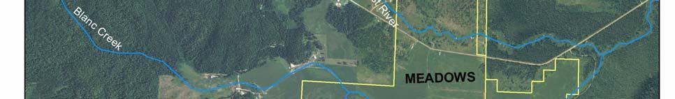

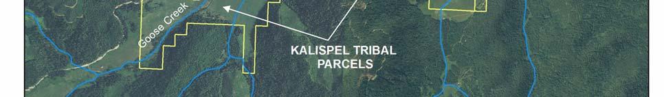
5 Figure 1. Goose Creek project location. 4
 deposits have been mapped as the valley fill (Figure 2).")
6 Geologic and Geomorphic Setting The geomorphic setting of the project reach reflects both the influences of bedrock geology as an upland sediment source as well as the effects of glacial and fluvial processes on valley fill deposits. Within the project area, Pleistocene and Holocene glacial and lacustrine (lake) deposits have been mapped as the valley fill (Figure 2). These glacio-lacustrine deposits reflect the location of the lower Goose Creek drainage on the southern margin of the Cordilleran Ice Sheet between 12,000 and 16,000 years ago. Carrara and others (1996) concluded that, west of the project area in easternmost Washington, ice extended as far south as Springdale (the Colville ice lobe) and Newport (Pend Oreille River lobe). Just east of Goose Creek, Glacial Priest Lake was a long-lived glacial lake that experienced at least 14 episodes of backflooding from catastrophic flooding from Lake Missoula ( The project reach is thus located within a transitional area between south-trending ice lobes and ice-margin lake environments (Figure 3). Subsequent deglaciation has been associated with the formation of peat bogs in the Colville Valley (Carrara and others, 1996). Figure 2. Geologic map of project area (Lewis and others, 2008). The geologic mapping in the project reach (Figure 2) coupled with pit stratigraphy collected in support of channel design indicate that glacio-lacustrine conditions did exist in the project area resulting in the deposition of fine grained glacial lake deposits, and overlying peats are associated with subsequent deglaciation. The headwaters geology above the project area consists of Proterozoic-age Belt Supergroup rocks, as well as granodiorites that have been tentatively mapped as Cretaceous in age (Figure 2). Belt geology weathers to predominantly clay and silt sized particles (IDEQ, 2001). The Cretaceous-aged granites, which form the majority of the upper watershed area, weather to very fine gravel and sand-sized particles (1-8mm; IDEQ, 2001). These sands and fine gravels are 5

7 observed at depth in soil pits as well as within the current channel bed. In the soil pits a sharp boundary separates peat deposits from overlying fluvial sands and fine gravel. This fluvial sand unit reflects an abrupt transition from post-glacial peat bog conditions to a fluvial environment with a predominantly sand sediment source. Floodplain silts and clays typically overly the sand sequence. Figure 3. Mapped southern extent of Cordilleran Ice Sheet ( The observed series of sands and overlying silts is consistent with soils mapping in the area. The soil unit mapped in the project reach is the Bonner General Soil Map Unit (IDEQ, 2001). The Bonner unit is of glacial outwash origin, with very deep, level to undulating, well drained soils. Its surface layer is silt loam, subsoil is gravelly silt or sandy loam, and the substratum is very gravelly loamy sand or very gravelly coarse sand. 6

8 Figure 4. General soil types of the Priest River Basin (IDEQ, 2001). 7
9 Existing Habitat Conditions Due to the considerable length of channel through Big Meadows, aquatic and riparian habitats of Goose Creek vary in quality depending on the location within the valley. In addition, the creek exhibits various geomorphic characteristics which allow it to be divided into shorter sub-reaches for the purposes of habitat descriptions. Figure 5 displays reach breaks as identified by various habitat characteristics during the field survey. The reaches described in this section do not necessarily correspond with channel slope breaks or restoration phases as described in subsequent sections of this report. Figure 5. Reach breaks for Goose Creek in Big Meadows. 8
, the channel does not appear incised and has adequate access to a natural floodplain.")
10 Upstream of Project Reach As Goose Creek exits the steeper, forested areas of the watershed and enters the flatter meadows, the creek has a high density of beaver complexes and good fish habitat complexity. At the upper Forest Service road crossing (not shown in Figure 5), the channel does not appear incised and has adequate access to a natural floodplain. Stream banks are well vegetated with mature alder providing an overstory layer and mixed grasses and forbs along the stream banks (Figure 6). The channel begins to show signs of incision downstream of the upper road crossing. Once the creek reaches the upper extent of the southwestern Tribal parcel, the channel indicates signs of incision and lateral erosion (Figure 7). Bank heights are much higher and an inset floodplain has formed at a lower elevation than the meadow. Many banks are not as densely vegetated and some near vertical as the channel has dropped in elevation. Vegetation density remains moderately dense and overstory canopy layers provide good shade and cover. Beaver dams remain relatively common and fish habitat complexity is good in Goose Creek upstream of the Tribal parcel. Figure 6. Goose Creek upstream of the upper Forest Service road crossing. 9

11 Inset floodplain Increased bank heights Evidence of channel downcutting Figure 7. Goose Creek at southwestern Tribal parcel boundary 10

12 Reach A Reach A extends from the upper end of the southwestern Tribal parcel to an access road bridge crossing. As the channel enters the Tribal Parcel, it is incised with an inset floodplain developing approximately eight feet below the meadow elevation. Beaver activity is much less common, therefore backwater pools are less frequently found as compared to upstream. The channel exhibits a natural meander pattern throughout the upper extent of Reach A and provides relatively good habitat complexity and moderately dense riparian vegetation along the inset floodplain. As the creek approaches the access road, it deviates from its historic meander pattern and enters a channelized reach which continues downstream to the bridge crossing. Once the creek becomes channelized, habitat complexity becomes drastically reduced. Pool quality is degraded due to the absence of meander sequences and shrub cover is reduced to a thin boundary of alders along the fringe of the channel. Much of the creek has been armored along the access road to protect it from eroding at high flows. Overall habitat quality in this channelized reach is poor due to planform simplification and altered riparian complexity. Access Road Channelized Reach of Goose Creek Figure 8. Channelized segment of Goose Creek in Reach A. 11

13 Reach B Reach B extends from the bridge crossing to a forested portion of the valley bottom. The entire length of Goose Creek in Reach B is channelized. The creek acts more like a drain and conveyance ditch through Reach B and has virtually no habitat complexity in the form of riffle/pool sequences. Aquatic habitat is available in the form of woody debris, as the channel is lined with large alders on both banks. The channel is moderately incised and drains adjacent hay pastures. Upland grasses and forbs grow down to the edge of the channel but provide little cover or habitat. Although the creek has been altered to maximize hay production in this portion of the valley, the stream banks have generally maintained lateral stability and riparian vegetation is vigorous along a thin band immediately adjacent to the creek. Overall habitat quality is relatively poor in Reach B due to simplified plan form, lack of a functional floodplain, and reduced riparian vegetation complexity. Historic Floodplain Elevation Incised Channel in Reach B 7 Existing Bed Elevation Figure 9. Channelized portion of Goose Creek in Reach B. 12

14 Reach C Reach C of Goose Creek flows through a short, forested portion of the valley and continues into the center of Big Meadows. The channel returns to its historic meander pattern through this reach as identified by 1932 aerial photos. Although the channel displays a relatively natural sinuosity in Reach C, it also shows evidence of vertical incision of the stream bed, including an elevated meander cutoff, high banks, and thin band of riparian vegetation along the immediate banks. Habitat complexity improves in Reach C as compared to the channelized portions in Reaches A and B as the channel is able to scour pools on outside meander bends. Although habitat complexity begins to improve, the bed elevation of the creek is very low as compared to the meadow, and therefore acts as a drain for adjacent pastures used for grazing and producing hay. Riparian vegetation is relatively sparse due to a channel which has been disconnected from its historic floodplain. Bank erosion is evident by sloughing along much of the channel, which provides additional sediment inputs to the watershed. Dry, upland vegetation up to edge of stream banks Thin band of riparian veg Figure 10. Goose Creek in the lower portion of Reach C. 13

15 Reach D Reach D extends to a culvert which has been placed in the channel to provide a crossing for equipment access. The creek flows along nearly the same meander pattern as shown in 1932 aerial photography, indicating relatively minor lateral movements in the past 70 years. The channel continues to show signs of incision, including high bank heights, inset floodplain formation, and sparse riparian vegetation along the fringes of the channel (Figure 11). The relatively natural sinuosity in Reach D enables pool formation along the outside of meander bends that provide added habitat complexity. However, riparian vegetation throughout the reach has been reduced to a very thin band of grasses and occasional alders which provide little cover and shade. Overall aquatic habitat in Reach D is poor due to eroding banks, poor riparian vegetation density, and reduced floodplain connectivity. Poor riparian vegetation Inset floodplain bar formation High, vertical banks Figure 11. Goose Creek in Reach D showing inset floodplain formation and incised channel. 14
 to drain the meadow and improve hay production.")
16 Reach E Reach E of Goose Creek extends downstream of the culvert to a bridge crossing at the lower end of Big Meadows. The majority of this reach has been recently channelized and dredged (~10-15 yrs ago) to drain the meadow and improve hay production. As a result, habitat complexity is severely degraded and woody riparian vegetation is nearly absent throughout the reach. Sparse alders remain along the fringe of the channel and provide some cover and shade, but the majority of the channel has little overstory or canopy layer. Immediately downstream of the culvert, the channel remains incised with very high bank heights, one large meander cutoff, and upland vegetation growing up to the channel edge. The degree of incision lessens as the channel approaches the east side of the meadow, although it remains channelized to the bridge. As the channel begins to regain connectivity to its natural floodplain near the downstream end of the reach, vegetation characteristics favor more wetland species, denser alders, and spirea. Habitat complexity in Reach E is poor due to the simplified planform and highly altered riparian corridor. Channelized for drainage Poor riparian vegetation Figure 12. Channelized portion of Reach E. 15

17 Reach F Reach F of Goose Creek extends downstream of the bridge at the east end of the meadow to the confluence of Goose Creek and the Upper West Branch of the Priest River. Although short, this reach exhibits some of the most superior habitat conditions in the lower watershed. The channel has not been mechanically altered downstream of the bridge and channel incision is not evident. Riparian vegetation is dense and provides ample cover and protection from bank erosion. The channel abuts a forested hillside which provides a source of woody debris and habitat complexity. Surveys in Reach F provide potential reference conditions for habitat, channel dimensions, and riparian vegetation composition for other reaches upstream of Reach F. Figure 13. Goose Creek in Reach F just upstream from the confluence of the Upper West Branch of the Priest River. In summary, in-stream and riparian habitat quality along the lower five miles of Goose Creek is generally poor due to mechanical alterations to the channel plan form and the drastic reduction of a functional floodplain and riparian corridor. Over 8,000 feet of the creek has been dredged and channelized, resulting in vertical instability and downcutting of the stream bed from the east end of Big Meadows to well above the Tribal parcels. Portions of the channel are developing an inset floodplain and regenerated a healthy riparian zone; however, the majority of the creek has only a very thin band of vegetation along the channel which provides little in the form of cover, shade, and protection from lateral erosion. Within much of the project reach, Goose Creek has 16
18 downcut into sands and silts that comprise the upper valley fill stratigraphy; and in some locations, the channel has incised through these units and into an underlying peat horizon. Modifications to the stream channel over the past 75 years were designed to improve agricultural operations throughout Big Meadows by lowering the groundwater table and draining inundated floodplain soils. The alteration of groundwater hydrology has resulted in the conversion of what was formerly a large wet meadow and wetland complex to a large pasture dominated by upland pasture grasses suitable for grazing and hay production. The loss of wetland hydrology has drastically reduced the acreage of functional wetlands and the associated ecological benefits of water quality, water quantity, stream stability, and waterfowl, amphibian, and fisheries habitat in Big Meadows. 17
19 Geomorphic surveys of Goose Creek In order to begin developing a conceptual plan for restoring aquatic, riparian, and wetland habitats in Goose Creek and Big Meadows, several site visits and surveys were conducted in the fall of These surveys included: Project area topography 17,500-ft longitudinal profile of Goose Creek thalweg, bankfull, and terrace elevations, 29 existing channel cross sections, Four historic channel cross sections, 13 Wolman pebble counts to document stream bed composition, Mapping potential borrow sources of wetland sod, Six test pits, one in each of Reaches A, B, C, D, and E. Results of these investigations are provided in the following sections. Longitudinal Profile Tribal fisheries technicians completed a longitudinal profile of Goose Creek, including elevations of terraces, bankfull indicators, and the channel thalweg. Results of this survey allow calculations of channel slope throughout the project reach starting from the upper Tribal parcel boundary to the confluence of Goose Creek with the Upper West Branch (Figure 14). The red lines on this figure delineate breaks in channel gradient and do not correspond to the reach breaks illustrated in Figure 5. 18
20 Figure 14. Longitudinal profile of Goose Creek showing thalweg and terrace elevations. Goose Creek Longitudinal Profile 2470 Thalweg R Terrace Confluence Upper West Branch Elevation (ft) Slope = 0.16% Upper Tribal Parcel Boundary Slope 0.30% Slope 0.17% Slope 0.06% Slope 0.17% Station (ft) 19
21 Existing Channel Cross Sections Cross sections were surveyed in the fall of 2009 to determine dimensions of the channel at varying locations in the valley and the degree of incision, and to assist in developing a hydrologic model for Goose Creek. A total of 29 cross sections were surveyed including four in Reach A, six in Reach B, five in Reach C, five in reach D, four in reach E, and five in Reach F. Results of these surveys include bankfull channel width, bankfull cross sectional area, bankfull maximum depth, bankfull mean depth, and width/depth ratio (Table 1). All dimensions are based on a bankfull discharge estimate of 160 cfs (see Hydrology Section). Cross section plots are included in Appendix A. Table 1. Cross section parameters surveyed in Goose Creek X Section Type Wbf Max Depth Mean Depth XS Area W/D Ratio A1 Pool A2 Pool A3 R iffle A4 R iffle B B B B4 Pool C 1 R iffle C 2 R iffle C 3 R iffle C 4 Pool D1 Pool D2 Pool D3 R iffle D4 R iffle E E F F F F3 Pool F4 R iffle Average All Average Riffles Average Pools Goos e Creek Cross Sections
22 Historic Channel Cross Sections Due to the relatively recent channelization of Goose Creek in Reach E, short portions of the historic, deactivated channel are still intact. In an attempt to document historic channel dimensions, four cross sections were surveyed within a 750-foot deactivated channel segment in Reach E. Results of these cross sections are included in Table 2. Plots of each cross section are included in Appendix A. Table 2. Cross section parameters for deactivated channel segment in Goose Creek, Reach E. Goose Creek Historic Cross Sections X Section Wbf (ft) Max Depth (ft) Mean Depth (ft) XS Area (s q ft) W/D Ratio Ea Eb Ec Ed Average All Bed Composition The bed substrate of Goose Creek was sampled using the Wolman pebble count method of sampling particle sizes by size classification. Pebble counts were sampled at 14 locations on Goose Creek and were analyzed to determine the D50 (mean particle) and D84 (84 th percentile) size classes (Table 3 and Appendix B). Mean particle size ranged from silt/clay (<0.62 mm) to very fine gravel (4.3 mm). D84 size ranged from medium sand (0.9 mm) to coarse gravel (45 mm). These results suggest the bed substrate is dominated by smaller sized substrate classes including silt, sand, and fine gravels whereas the channel is capable of transporting larger sized classes including coarse gravels (Figure 15). The sand dominated bed of Goose Creek reflects upstream sediment sourcing of primarily Cretaceous-age granodiorites, with some input from of silts and clays from Proterozoic Belt Supergroup rocks (IDEQ, 2001). Table 3. Pebble count results for Goose Creek. Pebble Count Location D50 (mm) D50 Class D84 D84 Class A2 0.9 Medium sand 6.8 Very fine gravel A4 3.8 Very coarse sand 6.1 Very fine gravel B3 <.062 Silt/clay 5.5 Very fine gravel B4 <.062 Silt/clay 4.2 Very fine gravel C2 <.062 Silt/clay 5 Very fine gravel C4 0.7 Medium sand 2.33 Very coarse sand D Very coarse sand 7 Very fine gravel D2 0.8 Medium sand 45 Coarse gravel D Very fine gravel 7.5 Very fine gravel D Very coarse sand 7 Very fine gravel E1 0.5 Medium sand 0.9 Medium sand E2 3 Very coarse sand 5.5 Very fine gravel F3 0.7 Medium sand 0.9 Medium sand F4 0.9 Medium sand 37 Coarse gravel 21

23 Figure 15. Concentrated gravels in channel bed, Goose Creek. 22
.")
. Figure 17.")
24 Soil Pits In the fall of 2009, six soil pits were excavated by backhoe within the project reach to characterize subsurface materials (Figure 16). Pit locations were selected to provide a general representation of subsurface conditions on the anticipated reconstructed channel course (Figure 17). Total pit depths ranged from 6.5 to 9.5 feet; maximum excavation depths were limited by pit wall stability, groundwater levels, or backhoe reach (Figure 18). Appendix C contains the field logs collected for each pit. Figure 16. Backhoe used in soil pit excavation (Soil Pit 1). Figure 17. Soil pit locations, Goose Creek project reach. 23


25 Figure 18. Backhoe pit showing maximum depth at approximately 7.5 feet (Soil Pit 2). A generalized profile of the observed pit stratigraphy is shown in Figure 19. The plotted results show that in the lower portion of the valley, clay and peat were encountered in the deepest portion of the section. The clay encountered at the base of both Soil Pit1 and Soil Pit 2 consists of a blue/gray, highly cohesive massive clay (Figure 20). The unit was 1.0 to 1.3 feet thick, which should be considered a minimum thickness as the lower contact elevation is unknown. In Soil Pit 2, the clay contained some interbeds of gray sand. Overlying this unit, a peat unit ranges in thickness from 4.5 feet in Soil Pit 1 to 2.0 feet in Soil Pit 2, indicating that the unit may thin in the up-valley direction. This unit consists of a brown peat that has a low density and contains distinct reedy plant fragments (Figure 21). Neither the basal clay nor overlying peat were observed in any of the pits located up-valley from Pit #2. If these units were deposited in relatively flat lake or bog conditions, they likely extend up-valley at a deeper level than that reached by Pits #3 through #6. 24

26 Goose Creek Soil Pit Profile Pit 5 Pit 4 Pit 3 Pit 2 Top of Ground Top of Sand Top of Peat Top of Clay Base of Pit Pit Elevation (ft) Distance up valley from Pit #1 Figure 19. Soil pit profile compiled from pit logs and site elevation survey. Figure 20. Basal glacial clay, Soil Pit 1. 25
.")
27 Figure 21. Peat material excavated from Soil Pit 1. In Soil Pit 1 and Soil Pit 2, the peat layer was overlain by non-cohesive, granitic sands that contain distinct channels, reflecting deposition in a fluvial or deltaic environment (Figure 22). This sand horizon extends upvalley, forming the basal section of Soil Pits 3, 4, 5, and 6. The concentration of wood fragments in this sand horizon increased markedly in the up-valley direction (Figure 23). In all of the soil pits, the sand horizon was overlain by variably stratified fine silts. In some locations, a distinct ash horizon was present within the silt. This unit was consistently several feet thick and sufficiently indurated to provide stability to the pit walls. In most cases, the uppermost portion of this unit was massive and structureless, suggesting that it had been tilled as part of agricultural activities in the valley. In Pit 5, the silts overly a non-cohesive, convex bar deposit that suggests overbank infilling of an abandoned channel segment (Figure 24). 26


28 Figure 22. Wall of Soil Pit 2 showing non-cohesive, sand channel overlying peat. Figure 23. Wood fragments excavated from non-cohesive sand horizon, Soil Pit 4. 27


29 Figure 24. Massive silts overlying a convex point bar deposit of non-cohesive sands, Soil Pit 5. The results of the soil pit investigation indicate that the valley fill stratigraphy within the project area is geotechnically quite variable. As a result, the perimeter of the restored channel will vary depending on its vertical location in this stratigraphic sequence. In the eastern part of the valley, the deepest observed unit is comprised of cohesive clays. This unit, which is approximately 8.5 feet below the existing ground surface, is likely a glacial lake deposit, which may be associated with Glacial Priest Lake. The interbedded clay and sand layers in Pit #2 suggest that this area was on the lake margin when these deposits were laid down. The overlying peat unit indicates a post-glacial bog environment, which is consistent with conditions found to the west in the Colville Valley (Carrara and others, 1996). Following peat deposition, the environment became more fluvial in nature, and non-cohesive sands derived from upper watershed granitic sources were deposited across the valley. Silt deposition over the sands indicates a long period of floodplain deposition across the valley, and the disturbance of the upper portion of this unit is indicative of ground leveling or tilling in support of agricultural land uses. 28

30 Reference Reach Surveys on Upper West Branch In addition to the surveys performed along Goose Creek, a potential reference reach was identified on the Upper West Branch (UWB) of the Priest River. This reach of the Upper West Branch also flows through a meadow complex and visually exhibited similar sand-dominated substrate and channel dimension as Goose Creek. The selected reach showed no influence of anthropogenic alterations upstream or downstream and displayed a healthy riparian corridor and intact floodplain. Reference reach surveys included: 2,000 foot longitudinal profile, 12 channel cross sections, 7 Wolman pebble counts to document stream bed composition. Figure 25. Photo of Upper West Branch of the Priest River in reference reach. 29
31 UWB Longitudinal Profile A 2,000 foot longitudinal profile was surveyed in the selected reference reach of the Upper West Branch. Results of this profile allow for comparisons of channel slopes to those found in Goose Creek. Results of the longitudinal profile are illustrated in Figure 26. Thalweg slope averaged ft/ft for this reach of the Upper West Branch. Longitudinal Profile - Upper West Branch Eevation (ft) Station (ft) Figure 26. Longitudinal profile of Upper West Branch reference reach. UWB Cross Sections 12 cross sections were surveyed within a 2,000 foot reach of the Upper West Branch of the Priest River. Cross sections were surveyed at riffles and pools to assist in developing design dimensions for restored reaches of Goose Creek. Analysis of the surveyed cross sections included bankfull width (Wbf), maximum bankfull depth, mean bankfull depth, cross sectional area, and width/depth ratio. Results of this analysis are included in Table 4. Table 4. Reference reach cross section parameters in Upper West Branch of Priest River Upper Wes t Branch Reference Reach Cross Sections X Section Type Wbf (ft) Max Depth (ft) Mean Depth (ft) XS Area (sq ft) W/D Ratio Section 1 Riffle Section 2 P ool Tail Section 3 Pool tail Section 4 Pool Section 5 Riffle Section 6 Pool tail Section 7 Riffle Section 8 Pool Section 9 Riffle Section 10 Riffle Section 11 Pool Section 12 Riffle Average All Average Riffles Average Pools
32 Reference Reach Pebble Counts Seven pebble counts were sampled on the Upper West Branch reference reach to document the bed substrate composition. Mean particle sizes (D50) ranged from 0.8 mm (medium sand) to 5.9 mm (very fine gravel). The 84 th percentile (D84) of particle sizes ranged from 3 mm (very coarse sand) to 8.5 mm (fine gravel). Table 5. Pebble count results for UWB. Pebble Count Location D50 (mm) D50 Size Class D84 (mm) D84 Size Class Station Very fine gravel 7.5 Very fine gravel Station Very fine gravel 8.5 Fine gravel Station 3 4 Very fine gravel 7.8 Very fine gravel Station Medium sand 3 Very coarse sand Station Coarse sand 3.8 Very coarse sand Station Very coarse sand 7.5 Very fine gravel 31
33 Additional Investigations Field surveys provided valuable information as to existing channel, vegetation, and habitat conditions within the project area. Further investigations conducted following the field surveys include hydrology and the historic planform geometry of Goose Creek. These additional parameters are useful components for developing a restoration design. The following sections summarize the additional data compiled in these investigations. Hydrology Goose Creek is an ungaged creek with no available historic discharge data available. A water level recorder was placed in the creek near its mouth in 2009; however, these data were not available during the conceptual design phase. Developing estimates of Goose Creek s hydrology is an important component of the restoration design. Four methods of estimating various return intervals were analyzed to assist in developing a design discharge for Goose Creek. Method 1 Regional Regression USGS regional regression equations provide estimates of various return intervals for ungaged streams (Berenbrock 2002; USGS Idaho StreamStats website). The variables for the regression equations for northern Idaho include the drainage area (sq miles), mean basin elevation (ft), and percentage of the watershed that is forested. Return interval results for Goose Creek at its mouth using the regression equations for Idaho are included in Table 6. Table 6. Idaho regional regression return intervals for Goose Creek Return Interval Q (cfs) Method 2 WinXSPro Model on Goose Creek Cross Sections The WinXSPro model estimates at-a-station discharge at various water surface elevations using a basic Manning s equation approach. Model inputs include cross section station and elevation points, channel slope, and Manning s n. The Manning s n value accounts for roughness and is based on the materials present in the channel (sand, gravel, cobbles, etc.). Model output includes a bankfull discharge where the channel has reached full capacity. 32
34 This method is most appropriate for estimating bankfull flows at reference riffles. Goose Creek did not exhibit true reference conditions within the project area due to anthropogenic alterations, channelization, dredging, downcutting, and floodplain discontinuity. Selected cross sections input into WinXSPro included riffles surveyed in Reach F near the mouth of Goose Creek, and deactivated channel segments surveyed in Reach E where bankfull indicators are well developed. Results of these calculations are provided in Table 7. Table 7. Estimated bankfull flows using WinXSPro at surveyed cross sections in Goose Creek. Cross Section input to WinXSPro Bankfull Q (cfs) XS F2 232 XS F4 263 XS Ea 173 XS Eb 109 XS Ec 117 XS Ed 94 Average 165 cfs Method 3 Estimates of Velocity using Hydraulic Equations This method attempts to determine water velocities at a station using hydraulic calculations based on channel cross section dimensions, slope, and bed particle size to determine a value for Manning s n. Values for wetted perimeter, hydraulic radius, and R/d84 were calculated for reference cross sections surveyed in Goose Creek. These parameters are used in three hydraulic calculations to estimate various Manning s n values which allowed an estimation of velocity using Manning s equation. With a velocity estimate, bankfull discharge was estimated as the product of velocity and cross sectional area. The resulting estimates of bankfull flow for Goose Creek are shown in Table 8. Results of each of these methods are shown in Table 9 through Table 11. Table 8. Hydraulic variables for channel cross sections in Goose Creek. XS Wetted Wbf D84 D84 Slope XS Area Perimeter (ft) (mm) (ft) (ft/ft) (sq ft) (ft) Hydraulic Radius (ft) R/D84 (ft) Manning s n using R/D84 F F Ea Eb Ec Ed D bkf - Bankfull Mean Depth = (A bkf /W bkf ) WP - Wetted Perimeter = (2*D bkf )+W bkf W bkf - Bankfull Width R - Hydraulic Radius = A bkf /WP S - Slope 33
35 Table 9. Method #3a Relative Roughness to Determine Manning s n Manning s Velocity XS Area Cross Section n using (ft/sec) (sq ft) R/D84 Qbf (cfs) XS F XS F XS Ea XS Eb XS Ec XS Ed Average 144 cfs Table 10. Method #3b u/u* = 2.38+log(R/D84) Cross Section u*=(grs)^0.5 Velocity XS Area (ft/sec) (sq ft) Qbf (cfs) XS F XS F XS Ea XS Eb XS Ec XS Ed Average 159 cfs Restoration of Goose Creek and Big Meadows Table 11. Method #3c Jarrett s Equation for estimating Manning s n: n=0.39s 0.38 R Cross Section Manning s n Velocity XS Area Jarrett s (ft/sec) (sq ft) Qbf (cfs) XS F XS F XS Ea XS Eb XS Ec XS Ed Average 150 cfs The use of multiple methodologies for predicting return intervals and estimating bankfull flows provides a range of discharges that are likely to regularly occur in Goose Creek. The 2-year return interval is not necessarily a prediction of a bankfull flow event, but provides one tool for estimating regular return flows. Table 12 summarizes discharges calculated for Goose Creek using the various methodologies employed to develop a design discharge. 34
36 Table 12. Hydrology summary for Goose Creek design discharge Method Q (cfs) USGS Regression Equations 2 year return interval 162 WinXSPro Average bankfull discharge at surveyed riffles 165 Relative Roughness to determine Manning s n 144 u/u* to determine Manning s n 159 Jarrett s Equation to determine Manning s n 150 Restoration of Goose Creek and Big Meadows Historic Channel Planform Typical planform characteristics of rivers include sinuosity, radius of curvature, belt width, and meander length. Each of these characteristics is important in designing a restored channel which will maintain stability and provide appropriate habitat features. Historic aerial photography provides a very useful tool in quantifying planform attributes of streams prior to significant human alterations. Aerial photographs of Big Meadows were taken in 1932, and provide excellent documentation of Goose Creek s planform characteristics prior to channelization and dredging. Sinuosity Historic segments of Goose Creek were digitized to determine channel sinuosity at various locations within Big Meadows and to provide design guidance for the restored stream. The 1932 photography revealed reaches within Big Meadows where the channel lost definition, resulting in discontinuous channel digitization. Poor channel definition may be due to areas of the meadow that are particularly flat and contain a braided channel, areas where the channel has a very dense riparian corridor which overlays the channel, or where the reduction in image quality prevents obvious identification of the channel. Figure 27 illustrates historic and existing channel planform of Goose Creek through Big Meadows and includes calculated sinuosity for each digitized channel segment. Channel segments in this figure do not necessarily correspond to slope breaks in Figure 14 or reach breaks in Figure 5. 35
37 Figure 27. Historic and existing channel planforms and calculated sinuosity of Goose Creek in Big Meadows. 36

38 Belt Width, Meander Length, and Radius of Curvature Each of these planform components was measured for each meander sequence within each of the 1932 channel segments illustrated in Figure 27. An example illustration of digitized meander lengths, belt widths, and radius of curvature from the 1932 aerial photos along lower Reach E is shown in Figure 28. Meander geometry results for each channel segment are included in Table 13. Figure 28. Planform dimensions digitized from 1932 aerials. Table 13. Planform geometry from historic Goose Creek channel. Channel Segment Reach Belt Width (ft) Meander Length (ft) Radius of Curvature (ft) Min Max Avg Min Max Avg Min Max Avg 1 Above A A Lower B C D/Upper E Lower E
39 Conceptual Design Criteria for Restoring Goose Creek and Big Meadows Project Goals The two goals of the Big Meadows restoration project are to 1) Restore aquatic, riparian, and wetland habitat within parcels owned by the Kalispel Tribe and neighboring landowners; and 2) Construct a fish passage barrier on Goose Creek to protect cutthroat trout populations from invasive brook trout. Specific criteria for meeting these goals include: Developing aquatic habitat features that are appropriate for the channel type and geomorphic setting of Goose Creek through Big Meadows; Developing various channel plan forms, profiles, and dimensions that provide vertical and lateral stability of the creek; Reestablishing connectivity between Goose Creek and its floodplain; Developing a riparian revegetation plan; Incorporating a structural passage barrier at least 4 high to prevent brook trout invasion at up to a 100 year flood event. The existing condition of Goose Creek precludes attainment of the project goals. The channel bed has dropped in elevation due to mechanical alterations, channelization, and dredging, resulting in a lower groundwater table and largely non-functional floodplain. The ecological benefits of a riparian corridor have largely been lost where the channel has downcut. Achieving the project goals may be accomplished by relocating Goose Creek back to its historic elevation and dimensions. Historic aerial photography provides evidence of a gently meandering channel through much of Big Meadows. The flat character of the meadows likely provided the original, expansive floodplain for Goose Creek, and may be utilized to provide that function again if the channel is reconstructed. Excavating a new channel through the meadow which is designed to provide adequate capacity and maintenance of lateral and vertical stability throughout its hydrologic regime is a feasible restoration approach. Design Elements The information provided in previous sections of this report can be utilized to help define appropriate parameters for successful channel restoration design on Goose Creek. These parameters relate to channel planform, cross section, hydrology, and sediment transport conditions. By integrating these parameters with project goals and site topography, a conceptual design can be developed. Channel Planform The proposed planform design for Goose Creek includes parameters of sinuosity (ratio of channel length to valley distance), and bendway shape (meander length, radius of curvature, belt width). These parameters have been developed for Goose Creek based on measurements of historic conditions, measurements of reference conditions, an understanding of existing topography, and the integration of a fish passage barrier into the design. 38
40 The measured historic sinuosity for Goose Creek ranges from 1.38 to This relatively high sinuosity defines a slope that reflects the total drop in elevation through the valley. In the restoration design, however, the inclusion of a 4-ft fish passage barrier will significantly reduce the available grade that can be used to lengthen the channel and increase sinuosity. With a design sinuosity ranging from 1.2 to 1.7, there will be ample opportunity to incorporate complex planform elements into the restoration design. Above the fish passage barrier, sinuosity will range from 1.4 to 1.7. In this area, the channel will be constructed high in the stratigraphic column such that the bank toe materials will consist largely of cohesive silts, with potentially some non-cohesive sands exposed locally in the bank toe (See Section on Anticipated Channel Perimeter Materials). Where silts comprise the channel margin, the channel can likely accommodate the low radius of curvature (Rc) values that were measured on historic air photos. These values range from 13 to 102 feet on identifiable historic channel segments. Using an average cross section width (W) of 25 feet from the deactivated channel segment in Reach E, the resulting Rc/W values range from less than one to four. Typically, Rc/W values less than approximately 2 are prone to limited sediment transport conveyance, backwatering, infilling, and cutoff or avulsion (Lagasse, et al, 2004). To maintain effective sediment transport through the reach, it is anticipated that Rc/W values will range from approximately 2 to 4. These bends will be contained within a meander belt that approximates that of the historic channel, which is up to 120 feet in width. Channel Slope Slope is an important component of channel design, as the combination of channel slope and channel cross section defines conveyance capacity, sediment transport capacity, and erosive energy. Currently, channel bed slopes within the project reach range from 0.06% to 0.3%. All of these channel segments have been modified, and thus do not provide a pristine reference condition. The channel slope on the Upper West Branch, which has been identified as a potential reference reach, is 0.25%. In Reach F, which exhibits excellent habitat and sediment transport conditions, the channel slope is approximately 0.17%. Slope is a direct reflection of channel length, and as such, it is directly related to sinuosity. If sinuosity is used as a primary design element, the resulting slope must be at an acceptable condition for stream stability. For this design, target sinuosities result in proposed design slopes that range from 0.12 % to 0.16%, which is similar to that of Reach F. This slope range is within the range of existing conditions and close to that of Reach F. In combination with the proposed cross section, the proposed gradients should maintain effective sediment transport through the reach. Design Discharge In order to appropriately size the channel, it is critical that a design flow be developed that approximates the bankfull condition of a stable channel configuration. Based on a combination of methods, the design discharge developed for Goose Creek is cfs. This estimate approximates both existing bankfull channel capacities, as well as results of regional regression analysis. Channel Cross Section As described above, cross section and slope are primary influences on the hydraulic conditions within a channel. Other factors such as bend radius of curvature and bed substrate also affect 39
41 these conditions, however to a lesser degree. To that end, cross section geometries have been developed to convey the design flow at an appropriate width to depth ratio. Conceptual cross sections have been developed for both pools and riffles. On the deactivated channel segment in Reach E, the average width to depth ratio is For existing conditions, average width to depth ratios are 14.9 for riffles and 11.5 for pools. W/D ratios in the Upper West Branch averaged This range of W/D ratios will be used to develop a range of pool and riffle dimensions for the newly constructed channel. Final channel dimensions will fluctuate within each reach to account for design slopes and habitat features. Sediment Transport The geology of the upper watershed, coupled with the observed valley fill stratigraphy, indicates that gravel and finer sediment comprise the sediment load delivered to the project reach. Pit stratigraphy shows strong sorting between the channel (fine gravel and sand) and floodplain areas (silts). It is anticipated that the integration of historic channel configuration into restoration design will similarly sort sediment, effectively conveying the sandy bedload through the channel and allowing the deposition of fine silts on the adjacent floodplain. The application of a relatively low width to depth ratio in riffle cross sections will help facilitate the sediment transport conditions. Channels of relatively high sinuosity (>1.5) and low width to depth ratios (<12) tend to be highly effective at sand transport. It should be noted, however, that some sediment storage and bar formation in the constructed channel should be expected as the channel adjusts following construction in response to roughness changes provided by vegetation, and hydrologic conditions that ensue. Floodplain Access The establishment of a functional, broad floodplain adjacent to the Goose Creek channel is an important component of restoration design. Above the fish passage barrier, the channel will be raised and reconnected to its historic floodplain. Where necessary, floodplain dikes will be integrated into the design to prevent flooding in areas where it would conflict with existing land uses. Even with this limited access to the historic floodplain, however, overall floodplain extent will increase dramatically relative to existing conditions. Downstream of the fish passage barrier, the channel will be too low to access its historic floodplain beyond bankfull conditions. In this area, the proposed cross section design includes the excavation of an inset floodplain surface that will range in width from approximately 70 to 90 feet. This inset floodplain will provide area that will dissipate flow energy beyond bankfull conditions, and also create additional opportunities with respect to riparian recovery in the reach. Uncertainty Some adjustment of the channel following construction should be expected and accommodated. Anticipated adjustments will include modifications in channel width due to lateral accretion on the channel margins, adjustments of pool depths in response to radius of curvature and flow conditions, and undercutting of the bank toe where non-cohesive sands are exposed. As the channel is constructed, it will be important to consider the need for local bank toe protection where the channel perimeter appears highly erosive. The allowance for some vegetative 40
42 recovery prior to the activation of reconstructed channels will significantly reduce the potential for short-term instability within the new channel. Project Implementation Relocating the channel to its historic elevation is possible by placing a plug across the existing channel that diverts flow into a newly constructed channel course. Using the meadow topography as a generalized elevation of the new floodplain, the new channel can be constructed at a proper sinuosity, gradient, and dimension to provide suitable riffle and pool habitat features. Following channel excavation, riparian revegetation and recovery will provide a suitable, well vegetated corridor along the new channel. Groundwater hydrology will be affected by the raised elevation of the new channel, and will likely return the project area into a wet meadow complex. Material generated by excavating the new channel can be used to fill the deactivated segments of Goose Creek. Placing a plug at the head of the new channel will result in a lengthy backwatered portion of Goose Creek upstream of the plug. This backwater feature will not result in flooding of the elevated meadow upstream of the reconstructed channel, because the existing channel is highly incised and able to contain additional water depths. Placing a fish passage barrier within the project area is challenging due to the relatively flat gradient of Goose Creek and Big Meadows. An effective barrier to prevent brook trout movement upstream must be a minimum of four feet high and pass 100 year flood flows. Typically, fish passage barriers are installed in locations where a creek flows through a relatively confined valley and has sufficient gradient to provide the vertical drop necessary to install a drop structure without significantly altering sediment transport. The topography of Goose Creek and Big Meadows does not provide sufficient gradient or valley constrictions to install an effective barrier if the entire channel is relocated to a historic elevation. However, a barrier may be installed if the bed elevation of the channel below the barrier is at least four feet below the bed elevation above the barrier. Following an analysis of various options for constructing a barrier, the most appropriate location for installing a passage barrier within Tribal property lies at the head of Reach E near the existing culvert and stream crossing. The culvert currently serves as a grade control structure and prevents the upstream migration of headcuts resulting from historic channelization and dredging activity below it. Downstream of the culvert, the channel is highly incised and the stream bed elevation lies 8.5 feet below the meadow. Sufficient channel cross section and meadow topography survey data have been collected to develop conceptual design elements of channel slope and floodway dimensions above and below a barrier if constructed at this location (See channel cross section E-1). Alternative locations for installing a barrier included at the mouth of Goose Creek, within Reach C on private lands, and upstream of Tribal lands. Each of these locations would require a check dam to act as a barrier and would result in a second backwatered reach of the Creek and a high probability of flooding issues. Subsequently, these alternative locations were determined to be inferior to placing a barrier near the existing culvert and excavating a lower floodplain elevation downstream of the structure. Barrier installation may be accomplished at the proposed location by excavating a new, lower floodplain and channel approximately 6.5 below the existing meadow elevation downstream of the barrier. Currently, the bed of the Goose Creek at the head of reach E is approximately
43 below the meadow; therefore, the newly built channel would be roughly two feet higher immediately below the barrier if installed in this location. Downstream of the barrier, the channel and inset floodplain may be excavated at a sufficient gradient to meet the existing channel on Tribal land near the east end of the meadow. Moreover, construction of a lower floodplain elevation below the barrier would alleviate flooding concerns in the eastern end of Big Meadows during high flow events. This portion of the meadow is extremely flat and would likely be inundated regularly if the reconstructed channel were designed to allow high flow events to escape the constructed channel boundaries. The barrier must prevent fish passage at regular flooding events as well as large flood events (100-yr return interval) to meet the project goals. Given the flat nature of the meadow, this can be achieved by constructing a low berm across the valley perpendicular to the barrier which will contain the 100-year event while maintaining the passage barrier. Dimensions of the berm will be determined by conducting a flood study using various predictions of flood discharges. A second floodplain berm may be necessary to contain flood flows from reaching agricultural operations on the private parcel that lies between the two main Tribal parcels. Again, the dimensions of the berm will be determined by conducting a flood study and will be designed to withstand a specific flood event. 42
44 Project Phases Due to the magnitude of the project area, the Goose Creek restoration plan has been broken into five phases, each of which can be accomplished in a calendar year. These proposed project phases do not necessarily correspond to the reach breaks defined in Figure 5, and were developed based on constructability. Each construction phase will need a final design completed in order to provide enough detail for a design/build approach. Each phase is described in more detail in the following sections. Phase 1 This phase will include constructing a new floodplain and meandering channel through the eastern (downstream) portion of Big Meadows. The downstream extent of this project phase is defined by the tie-in point to the existing channel on Tribal land, while the upstream extent is immediately below the fish passage barrier. Construction of the channel below the barrier requires a stream bed elevation at least four feet below the bed above the barrier; therefore, a floodway will be excavated at a lower elevation to allow construction of a meandering channel within it. This phase includes constructing approximately 3,560 feet of floodway which with a top width ranging between 70 and 90 feet. Approximately 4,275 feet of new channel will be excavated within the floodway. Material excavated from the new floodway and channel will be used to fill the deactivated channel segment and construct a floodplain dike. Additional material will be stockpiled to use as fill in subsequent project phases. A conceptual channel planform for Phase 1 is illustrated in Sheet 1. Planform sinuosity in the eastern extents of Big Meadows was historically 1.6 (Figure 27). Due to the incorporation of the fish passage barrier at the upper end of this phase dropping the channel elevation by four feet, the proposed channel sinuosity in Phase 1 is must be reduced to 1.2 to account for the reduction in gradient. Based on this planform configuration, the overall channel slope will be 0.12%. Four conceptual riffle cross sections downstream of the fish passage barrier are illustrated in Sheet 6. These cross section drawings illustrate the depth of excavation required to establish the new floodway and channel at four locations, including immediately above the barrier, immediately below the barrier, approximately half way between the barrier and the tie-in to the existing channel, and 400 feet upstream of the tie-in. These conceptual cross sections were used to develop material quantities required for excavation purposes. Floodplain revegetation will include seeding bare areas of excavation and planting riparian shrubs throughout the corridor. Allowing the channel banks and floodplain to revegetate naturally for 1-2 growing seasons prior to activating the channel would reduce the need for using coir fabric or other bioengineering treatments to maintain stability and would greatly reduce project costs. Revegetated areas will be irrigated prior to activating the channel in order to maximize survival and growth rates. Weed management is highly recommended for all disturbed areas, including the new floodplain, floodplain dike, and any spoil piles of material stockpiled for use in subsequent phases. 43
45 Prior to initiating construction, a final design will be necessary to provide sufficient details for a design/build approach. Final designs necessary to initiate this phase will include: Flood Hazard Study (for entire project area) Wetland Delineation and Jurisdictional Determination (for entire project area) Final Channel Design (Phase 1 reach only) Floodplain Dike Design Fish Passage Barrier Design The flood hazard study will include a determination of areas that are expected to become inundated (flooded) at various discharges in Goose Creek. This study will incorporate topographic data collected via LiDAR and hydrologic data discussed in this report to provide a map of anticipated flooded areas during out-of-bank flow events. Filling the existing channel and associated wetland fringe will require a permit from the U.S. Army Corps of Engineers (ACOE) as mandated under Section 404 of the Clean Water Act. Under this regulatory framework, the existing channel margins of Goose Creek will likely be classified as emergent riparian wetlands, while the bed of the channel will be classified as a perennial waterway (Cowardin et al 1979). Each of these wetland types are considered jurisdictional by the ACOE and typically require mitigation if more than 0.1 acres are impacted as a result of a particular project. The Goose Creek and Big Meadows Restoration Project will cap the entire length of the existing channel (>12,000 feet of channel), and will result in filling well over the 0.1 acre threshold required for mitigation. Mitigation of the impacted wetlands may potentially be accomplished in-kind by constructing the new channel and riparian corridor, which will add over 4,000 feet of additional channel, and elevate the water table to establish a wetland buffer along the channel. The ACOE will require a wetland delineation of the project area prior to formally issuing a jurisdictional determination (JD) of wetlands and waterways. The wetland delineation must include surveying and mapping jurisdictional wetlands within the vicinity of the project based on wetland hydrology, vegetation, and soils characteristics. Results of the delineation will allow a quantification of existing jurisdictional wetlands and provide a baseline for quantifying proposed impacts in these areas. The channel design will include finalizing the channel planform, profile, and cross section dimensions, volume calculations, revegetation plans, irrigation measures, erosion control, and equipment access and staging areas. Final plans will be used as construction documents during the implementation phase and may also be useful in obtaining additional regulatory permits. The floodplain dike will be designed following the flood hazard study to determine how the dike will affect valley flooding during various discharges. The dike will be designed to maintain structural integrity and barrier function during flood flows. A geotechnical investigation of existing soil properties as well as proposed dike materials will be necessary to properly engineer the floodplain dike. The fish passage barrier will need finalized structural designs and specifications in order to obtain construction bids. The barrier will be designed to maintain a 4 vertical drop and integrate into the floodplain dike. The barrier will also be designed to integrate a railroad car bridge to 44
46 maintain a stream crossing at the proposed site. Final designs of the barrier will incorporate Tribal objectives and biological passage requirements for all anticipated fish species. Phase 2 Phase 2 will include constructing the fish passage barrier and extending the new channel upstream an additional 3,170 feet (Sheet 2). The channel in this phase will be excavated to dimensions that allow the meadow to act as a floodplain and will take advantage of existing swales within the meadow to align the new channel. Sheet 6 illustrates proposed cross sections for riffles and pools upstream of the barrier. The new channel segment may be activated via a bypass channel from Goose Creek at the upstream extent of the phase. Material excavated to create the new channel will be stockpiled to fill the deactivated channel segment in subsequent phases. Historic planform sinuosity in this reach of Big Meadows was 1.4, which will remain the target sinuosity for Phase 2. This target sinuosity will result in an overall channel gradient of 0.16%. Historic belt width, meander length, and radius of curvature will be used to develop the geometric template of the restored channel. A floodplain dike will be constructed to maintain the fish passage barrier at high flows. The foundation and core of the dike should be constructed with suitable materials such as clay or gravel to prevent breaching at high flows. The clay layer could be capped with topsoil for revegetation purposes. A geotechnical analysis of existing soil conditions, permeability, and potential borrow sources is highly recommended during final engineering designs. The fish passage barrier will be installed to provide a 4 drop in elevation in the channel bed. Sheets 7 and 8 illustrate two alternatives for constructing an open channel barrier constructed of concrete. The barrier will include wing walls which will tie into the floodplain dike and a concrete apron to prevent fish jumping immediately below the barrier. Option 1 (Sheet 7) includes incorporation of a railroad car bridge immediately downstream of the barrier, and utilizes the walls of the barrier structure as bridge abutments. Option 2 (Sheet 8) incorporates the rail car bridge on the upstream side of the barrier, and would tie into the floodplain dike. The bridge could be structurally supported by the walls of the barrier, by fill material used to construct the dike, or both. Option 2 would compliment an access road that lies on top of the dike, whereas Option 1 would compliment an access road below the dike. Final designs will need to incorporate specifications for fish passage and structural components of the barrier in order to obtain sufficient construction bids. Phase 2 revegetation will include installing riparian shrubs along the riparian corridor. This could be accomplished by transplanting woody species from within the active channel, transplanting woody shrubs grown on site, or installing containerized plants. Revegetated areas will be irrigated prior to activating the channel in order to maximize survival and growth rates. Weed management is recommended for all disturbed areas, including spoil piles of material stockpiled for future phases. 45
47 This phase will also include activating the new channel and backfilling the existing channel through Phase 1. Stockpiled material excavated during Phase 1 will be used to completely backfill the deactivated channel. The reclaimed channel will be revegetated with seed mix and treated for weeds. A final channel design will include finalizing the channel planform, profile, and cross section dimensions, volume calculations, revegetation plans, irrigation measures, erosion control, and equipment access and staging areas. Final plans will be used as construction documents during the implementation phase. Phase 3 Phase 3 extends the new channel construction upstream an additional 4,535 feet (Sheet 3). As in phase 2, channel construction will utilize the meadow as a new floodplain elevation and construct a meandering channel across it. The upstream extent of this phase is at an existing equipment and livestock crossing at the eastern edge of the meadow. Historic planform sinuosity in this reach ranged from 1.4 in Reach B to 1.9 in Reach C. A target planform sinuosity of 1.4 downstream of the channel crossing will conform to the design sinuosity for Phase 2. Channel gradient in this portion of the new channel will be 0.16%. Upstream of the channel crossing, the target sinuosity will be reduced to 1.3 with an overall channel gradient of 0.15%. If necessary, a floodplain dike will be constructed along the western side of the new channel between the upstream end of Phase 3 and the channel crossing. This dike will prevent excessive flooding of agricultural operations on private land to the north of the new channel. The dimensions and length of the dike will be determined by results of the flood study. Revegetation of Phase 3 will include installing woody shrubs along the riparian corridor. Woody shrubs are available to transplant from the existing channel, plants grown on-site, or from nursery stock. Revegetated areas will be irrigated prior to activating the channel in order to maximize survival and growth rates. All disturbed areas will be reseeded and managed for weeds. This phase will also include activating the new channel and backfilling the existing channel through Phase 2. Stockpiled material excavated during Phases 1 and 2 will be used to completely backfill the deactivated channel. The reclaimed channel will be revegetated with seed mix and treated for weeds. The channel design will include finalizing the channel planform, profile, and cross section dimensions, volume calculations, revegetation plans, irrigation measures, erosion control, and equipment access and staging areas. Final plans will be used as construction documents during the implementation phase. 46
48 Phase 4 Phase 4 of the project includes extending the relocated channel segment 4,195 feet upstream to meet the existing channel above an access road near survey cross section A2. This channel segment will be activated by placing a plug in the existing channel just downstream of the head of the new channel. A new channel crossing will be constructed at the head of the creek and could be either a large culvert or bridge. Material excavated to create the new channel will be stockpiled to fill the deactivated channel in the final phase. No historic planform geometry is available for this portion of Big Meadows. In order to maintain a consistent gradient with downstream phases, the target planform sinuosity of this reach is 1.7, establishing an overall channel gradient of 0.16%. Revegetation efforts would include installing woody species along the riparian corridor of the new channel. Woody species transplants are available from the existing channel, may be grown on-site, or purchased from a nursery. Phase 4 will include activating the new channel segment constructed during Phase 3. Stockpiled material excavated during Phases 1 and 3 will be used to completely backfill the deactivated channel segment. The reclaimed channel will be revegetated with seed mix and treated for weeds. A new stream crossing will be necessary to provide private landowner access to parcels to the south of Big Meadows. This crossing could consist of a bridge or culverts to allow vehicle passage across the channel. The channel design will include finalizing the channel planform, profile, and cross section dimensions, volume calculations, revegetation plans, irrigation measures, erosion control, and equipment access and staging areas. Final plans will be used as construction documents during the implementation phase. In addition to the final channel designs completed for Phases 1-3, this phase will require designing a new channel crossing at the head of the relocated reach. Phase 5 The final phase of the project includes activating the newly constructed channel segment in Phase 4 and reclaiming the deactivated channel segment. Material stockpiled during Phase 4 will be used to fill the deactivated channel. Reclamation of the deactivated channel will include reseeding and treating for weeds. Activating New Channel Segments Each of the newly constructed channel segments may be activated by placing a plug in the existing channel to check water into the new channel. A short bypass channel will be necessary to activate Phases 1 and 2, as their upstream endpoints do not terminate at the existing channel. It will be advantageous to wait 1-2 growing seasons following the excavation of each channel segment before activating the channel to allow time for revegetation efforts to take hold. This approach would highly benefit from irrigation of the revegetated riparian corridor for the 47
49 duration of time between plant installation and channel activation. Irrigation is recommended because the water table will remain well below the proper, restored elevation until the channel segment is activated. The phases described above include activating new channel segments 1 year following construction; however, this plan could easily be amended to allow a 2 year growth period prior to channel activation. It is also possible to construct all phases of the new channel prior to activating any channel segments. This would allow the maximum time allotment for revegetation of the first phase. In this case, the fifth phase will include activating the entire channel and reclaiming all of the existing channel in one year. If the newly constructed channel segments are allowed to revegetate for 1-2 years following the initial construction phase, it will be necessary to provide some form of irrigation along the channel to maintain the riparian and wetland corridor. Although the existing channel is well below the anticipated elevation of the restored channel, it is expected the new channel will intercept localized sources of groundwater at some points of the growing season. Placing temporary check structures such as hay bales in the channel will check the water up and assist in irrigating plants along the channel fringe. If the Tribe maintains sufficient water rights on Goose Creek, temporary diversion structures could be placed to provide flood irrigation along the new channel. Anticipated Material Volumes Table 14 provides preliminary cut and fill volumes estimated for each phase as described above. Cut volumes include in-place material necessary for excavation from the floodway and channel in Phase 1 and for the channel in Phases 2-4. Fill volumes were estimated using the average area of surveyed cross sections in the existing channel and multiplying along the length of channel to be filled. These volume estimates are preliminary and should be further investigated in final designs. Table 14. Conceptual volume estimates, Phase 1-4. Phase Cut (cy) (IN PLACE) Fill (cy) Net 1 28,275 9,735 18, ,250 15,110-8, ,940 16,310-7, ,270 7,020 1,250 Total 51,735 48,175 3,560 These preliminary estimates reveal a net gain of ~3,500 cubic yards of material will be generated by excavating the new channel and floodplain. This material may be utilized to build the floodplain dike(s) and spread across upland areas and reseeded. The excess quantity of material generated from Phase 1 will need to be stockpiled along the existing channel for use in reclaiming it in subsequent phases. 48
50 49
51 50
52 51
53 52
54 53
55 Restoration of Goose Creek and Big Meadows EXISTING GROUND A A' EXISTING GROUND 24.3 FT 2.3 FT BANKFULL 4.6 FT RIFFLE CROSS-SECTION ABOVE BARRIER 22.3 FT BANKFULL POOL CROSS-SECTION ABOVE BARRIER B B' 90.4 FT AREA TO BE EXCAVATED EXISTING GROUND 4.2 FT 4.5 FT 24.3 FT 2.3 FT BANKFULL PROPOSED CHANNEL AND INSET FLOODPLAIN C FIRST RIFFLE CROSS-SECTION BELOW BARRIER C' 76.1 FT EXISTING GROUND AREA TO BE EXCAVATED 2.1 FT 24.3 FT 1.8 FT 2.3 FT BANKFULL PROPOSED CHANNEL AND INSET FLOODPLAIN SECOND RIFFLE CROSS-SECTION BELOW BARRIER D 71.4 FT EXISTING GROUND D' AREA TO BE EXCAVATED 1.8 FT 24.3 FT 2.3 FT 0.5 FT BANKFULL PROPOSED CHANNEL AND INSET FLOODPLAIN THIRD RIFFLE CROSS-SECTION BELOW BARRIER Goose Creek Conceptual Cross-Section Design Sheet 6 of 8 Date: 02/16/2010 Issued For: Conceptual Design PO Box 1133 Bozeman, MT Prepared for: Kalispel Tribe Drawn RLB Checked Approved MDS Drawing: proposed.dwg 54
56 RAILROAD FLAT CAR BRIDGE FLOW STREAMBED CONCRETE STREAMBED RIPRAP CROSS-SECTION VIEW 3.0 FLOW FLOW PLAN VIEW ISOMETRIC VIEW PO Box 1133 Bozeman, MT Goose Creek Conceptual Fish Barrier Design Road and Bridge on DS Side of Berm Prepared for: Kalispel Tribe Sheet 7 of 8 Date: 04/16/2010 Issued For: Conceptual Design Drawn Checked Approved RLB MDS Drawing: fish barrier.dwg 55
57 RAILROAD FLAT CAR BRIDGE FLOW STREAMBED 4.0 CONCRETE STREAMBED FLOW RIPRAP CROSS-SECTION VIEW FLOW PO Box 1133 Bozeman, MT PLAN VIEW ISOMETRIC VIEW Goose Creek Conceptual Fish Barrier Design Road and Bridge on Top of Berm Prepared for: Kalispel Tribe Sheet 8 of 8 Date: 02/16/2010 Issued For: Conceptual Design Drawn Checked Approved RLB MDS Drawing: fish barrier.dwg 56
58 Anticipated Channel Perimeter Materials and Implications for Channel Construction The reconfiguration of Goose Creek will include vertical shifting of the restored channel relative to the current channel. This change in channel bed elevation may result in the exposure of different boundary materials in the constructed channel relative to those that currently comprise the channel margin. In order to assess this potential change, the conceptual design for Goose Creek at the pit locations was assigned bed elevations for both pool and riffle cross sections, and these elevations are compared to the logged pit stratigraphy (Figure 29 and Table 15). In the uppermost part of the valley, the restored channel will be impounded at Soil Pit 6, such that the perimeter materials will not change. Downstream at Soil Pit 5, the channel perimeter at riffle cross sections will consist of silts, however the pools will likely extend down into non-cohesive sands. In this area, there is good potential for bank undercutting on the sand horizon, which could provide excellent habitat elements. Alternatively, excess undercutting on the sand horizon could result in localized upper bank collapse. Establishing a channel fringe with dense, wetland and riparian vegetation will be the key to maintaining lateral stability within this area. Field surveys identified no significant borrow areas for wetland sod to transplant along the stream banks. As a result, it would be advantageous to allow 1-2 growing seasons following channel construction to allow wetland vegetation to establish along the immediate bank line. This technique will reduce the potential for block failure and bank undercutting on the sand layer exhibited in Soil Pit 5. At the locations of Soil Pits 4, 3, and 2, the proposed channel is anticipated to be fully bound by cohesive silts, which will provide significant bank stability that will allow for complex planform elements, and maintenance of relatively low width to depth ratios once the banks are well vegetated. Planform stability will rely on wetland and woody species colonization along the banks. No significant wetland sod borrow sources were identified in the vicinity of the project reach; therefore it is recommended to refrain from activating these channel segments for 1-2 years following excavation. This timeframe will allow revegetation efforts to mature and wetland vegetation to establish along the channel fringe. At Soil Pit 1, the channel will be held within a deeper, compound cross section that contains an inset floodplain margin. As a result, the deeper cross section will extend down through the sands and into peat for both riffles and pools. Peat is similarly exposed in the bed of the existing channel to the north (Figure 30). Although bank failure is common in that channelized segment, the role of peat in that instability is unclear. This layer will not provide immediate bank and bed stability, although it may provide a rich source of seeds and organic matter. This layer may provide a very suitable medium for revegetation of the floodplain and stream banks. As stated earlier, it would be advantageous to refrain from activating this channel segment immediately following channel construction, and wait 1-2 growing seasons for revegetation efforts to mature. 57
 2435 2430 2425 10000 9000 8000 7000 6000 5000 4000 3000 Distance up valley from Pit #1 Figure 29. Valley fill stratigraphy and proposed riffle/bed elevations. 2000 1000 0 Table 15.")
59 Pit 6 Pit 5 Goose Creek Preliminary Design Bed Elevations Pit 4 Pit 3 Pit 2 Top of Ground Top of Sand Top of Peat Top of Clay Base of Pit Riffle Design Pool Design Pit Elevation (ft) Distance up valley from Pit #1 Figure 29. Valley fill stratigraphy and proposed riffle/bed elevations Table 15. Anticipated bed materials for pool and riffle cross sections at soil pit locations. Soil Pit Anticipated Riffle Anticipated Pool Anticipated Riffle Reference Bank Toe Bank Toe Bed Material ID Material Material Anticipated Pool Bed Material Soil Pit 1 Sand Peat Peat Peat Soil Pit 2 Silts Silts Silts Silts Soil Pit 3 Silts Silts Silts Silts Soil Pit 4 Silts Silts Silts Silts Soil Pit 5 Silts Silts Non-cohesive sands Non-cohesive sands Soil Pit 6 N/A (Backwatered) N/A (Backwatered) N/A (Backwatered) N/A (Backwatered) Figure 30. Peat exposures in bed of lower Goose Creek. 58
60 Conceptual Project Costs The following section provides total estimated project costs for design and construction for each phase as proposed in this conceptual design report (Table 16). Some components of each phase may be moved to other phases if necessary. For example, construction of the floodplain dike proposed in Phase 2 could be moved to Phase 1. Likewise, if an additional growing season is added to newly constructed stream segments, activation of that segment could be pushed back to a subsequent phase. Project final design costs for each phase are included in Table 17. Anticipated final designs for Phase 1 are considerably higher due to several additional components necessary to construct the first two phases of the project. Each phase includes a 3% increase per year for cost escalation (inflation). Given the recent turmoil of the construction industry, there is considerable uncertainty in labor, materials, and equipment costs over the next five years. In order to plan for this uncertainty as well as any unforeseen circumstances, a 20% contingency has been added to the overall project cost. 59
61 Table 16. Projected Design and Construction Costs for Goose Creek Restoration Project. Restoration of Goose Creek and Big Meadows 60
62 Table 17. (series) Phase 1-4 Final Design Cost Estimates Final Designs - Goose Creek Restoration Project Phase 1 Task No. Task Description Total 1 Flood Study $15, Cross Section Surveys $4, Hydraulic Modeling $7, Maps and Reporting $2,495 2 Wetland Delineation and Reporting $8, Wetland Delineation $4, Survey Wetland Boundary $ Write Report of Findings and Submit to ACOE $2,560 3 Final Channel Design $18, Final Volume Calculations $ Equipment staging, material placement $ Final Revegetation Plan $7, Final Channel/Floodway Drawings and Specifications $7, Final Irrigation Plan $1, Final Sediment Control Plan $680 4 Floodplain Dike Design $21, Geotechnical Soil Survey and Analysis $16, Floodplain Dike Designs and Specifications $4,685 5 Fish Passage Barrier Design $6, Structural Design $1, Hydraulics $1, Final Design and Specifications $4,100 6 Project Management $3, Contracting, Budget Management $1, Communications, planning, logistics $1,675 Total Cost $72,280 61
63 Final Designs - Goose Creek Restoration Project Phase 2 Task No. Task Description Total 1 Final Channel Design $12, Final Volume Calculations $ Equipment staging, material placement $ Final Revegetation Plan $3, Final Channel/Floodway Drawings and Specifications $6, Final Irrigation Plan $1, Final Sediment Control Plan $680 2 Project Management $1, Contracting, Budget Management $ Communications, planning, logistics $1,080 Total Cost $14,490 Final Designs - Goose Creek Restoration Project Phase 3 Task No. Task Description Total 1 Final Channel Design $13, Final Volume Calculations $ Equipment staging, material placement $ Final Revegetation Plan $3, Final Channel/Floodway Drawings and Specifications $6, Final Irrigation Plan $1, Final Sediment Control Plan $ Final Stream Crossing Design $1,020 2 Project Management $1, Contracting, Budget Management $ Communications, planning, logistics $1,080 Total Cost $15,510 62
64 Final Designs - Goose Creek Restoration Project Phase 4/5 Task No. Task Description Total 1 Final Channel Design $17, Final Volume Calculations $ Equipment staging, material placement $ Final Revegetation Plan $1, Final Channel/Floodway Drawings and Specifications $6, Final Irrigation Plan $1, Final Sediment Control Plan $ Final Stream Crossing Design $1, Bridge/Culvert Crossing Design $5,060 2 Project Management $1, Contracting, Budget Management $ Communications, planning, logistics $1,080 Total Cost $18,970 63
65 Literature Cited Berenbrock, C., Estimating the Magnitude of Peak Flows at Selected Recurrence Intervals for Streams in Idaho. U.S. Department of the Interior, USGS Water-Resources Investigations Report Carrara, P.E., E.P. Kiver, and D.F. Stradling, The southern limit of Cordilleran ice in the Colville and Pend Oreille valleys of northeastern Washington during the Late Wisconsin glaciation: Canadian Journal of Earth Sciences, 33, Cowardin, L.M. V. Carter, F. Golet, and E. LaRoe Classification of Wetlands and Deepwater Habitats of the United States. U.S. Department of the Interior, U.S. Fish and Wildlife Service, Washington D.C. Idaho Department of Environmental Quality (IDEQ), Priest River subbasin assessment and Total Maximum Daily Load: Idaho Department of Environmental Quality (IDEQ), Priest River subbasin assessment and TMDL: Appendix A, Sediment Model Assumptions and Documentation. Lagasse, P.F., L.W. Zevenbergen, W.J. Spitz, and C.R. Thorne, Methodology for predicting channel migration: Report prepared for National Cooperative Highway Research Program, Transportation Research Board of the National Academies, Project 24-16, 214 p Lewis, R.S., R.F. Burmester, R.M. Breckenridge, M.D. McFaddan, and W.M Phillips, Preliminary Geologic Map of the Sandpoint 30X60 Minute Quadrangle, Idaho Geological Survey Digital Web Map 94. USGS Idaho StreamStats Website: 64
66 Appendix A Plots of Surveyed Cross Sections in Goose Creek,
67 A1 7.0' A2 2.9' 6.7' A3 3.2' 5.1' A4 3.5' 5.7' 2.3' B1 6.5' 3.0' B2 4.5' 3.3' B3 3.4' 3.1' B4 3.5' 3.5' 2-YEAR DISCHARGE (160 cfs) WATER SURFACE 66
68 C1 4.8' C2 2.8' 5.1' 2.6' C3 C4 2.8' 2.2' 7.3' 3.1' D0 5.3' D1 2.5' 5.4' D2 2.3' 3.2' 4.4' D3 3.5' 2.8' D4 3.3' 2.5' 2-YEAR DISCHARGE (160 cfs) WATER SURFACE 67
69 E1 4.6' 3.5' E2 4.0' F0 2.5' 2.6' F1 5.3' 5.8' F2 3.7' 1.5' F3 3.5' F4 2.3' 2.9' 1.7' 2-YEAR DISCHARGE (160 cfs) WATER SURFACE 68
70 Appendix B Pebble Count Results for Goose Creek,
71 XS: A2 D 50 : 0.9mm XS: A4 D 50 : 3.8mm Reach: Pool D 84 : 6.8mm Reach: Riffle D 84 : 6.1mm CUMULATIVE PARTICLE SIZE DISTRIBUTION Sands Gravels Cobbles 120.0% CUMULATIVE PARTICLE SIZE DISTRIBUTION Sands Gravels Cobbles 120.0% 100.0% 100.0% Percent Finer Than 80.0% 60.0% 40.0% Percent Finer Than 80.0% 60.0% 40.0% 20.0% 20.0% 0.0% Particle Size (mm) 0.0% Particle Size (mm) XS: B3 D 50 : <.062mm XS: B4 D 50 : <.062mm Reach: Riffle D 84 : 5.5mm Reach: Pool D 84 : 4.2mm CUMULATIVE PARTICLE SIZE DISTRIBUTION CUMULATIVE PARTICLE SIZE DISTRIBUTION Sands Gravels Cobbles 120.0% Sands Gravels Cobbles 120.0% 100.0% 100.0% 80.0% 80.0% Percent Finer Than 60.0% 40.0% Percent Finer Than 60.0% 40.0% 20.0% 20.0% 0.0% 0.0% Particle Size (mm) Particle Size (mm) XS: C2 D 50 : <.062mm XS: C4 D 50 : 0.7mm Reach: Riffle D 84 : 5.0mm Reach: Pool D 84 : 2.33 mm 70
72 CUMULATIVE PARTICLE SIZE DISTRIBUTION CUMULATIVE PARTICLE SIZE DISTRIBUTION Sands Gravels Cobbles 120.0% Sands Gravels Cobbles 120.0% 100.0% 100.0% 80.0% 80.0% Percent Finer Than 60.0% 40.0% Percent Finer Than 60.0% 40.0% 20.0% 20.0% 0.0% 0.0% Particle Size (mm) Particle Size (mm) XS: D1 D 50 : 2.33mm XS: D2 D 50 : 0.8mm Reach: Pool D 84 : 7.0mm Reach: Pool D 84 : 45.0mm CUMULATIVE PARTICLE SIZE DISTRIBUTION CUMULATIVE PARTICLE SIZE DISTRIBUTION Sands Gravels Cobbles 120.0% Sands Gravels Cobbles 120.0% 100.0% 100.0% 80.0% 80.0% Percent Finer Than 60.0% 40.0% Percent Finer Than 60.0% 40.0% 20.0% 20.0% 0.0% 0.0% Particle Size (mm) Particle Size (mm) XS: D3 D 50 : 4.33mm XS: D4 D 50 : 2.66mm Reach: Riffle D 84 : 7.5mm Reach: Riffle D 84 : 7.0mm 120.0% CUMULATIVE PARTICLE SIZE DISTRIBUTION Sands Gravels Cobbles CUMULATIVE PARTICLE SIZE DISTRIBUTION Sands Gravels Cobbles 120.0% 100.0% 100.0% Percent Finer Than 80.0% 60.0% 40.0% Percent Finer Than 80.0% 60.0% 40.0% 20.0% 20.0% 0.0% Particle Size (mm) 0.0% Particle Size (mm ) XS: E1 D 50 : 0.5mm XS: E2 D 50 : 3.0mm 71
73 Reach: D 84 : 0.9mm Reach: Pool D 84 : 5.5mm CUMULATIVE PARTICLE SIZE DISTRIBUTION CUMULATIVE PARTICLE SIZE DISTRIBUTION Sands Gravels Cobbles 120.0% Sands Gravels Cobbles 120.0% 100.0% 100.0% 80.0% 80.0% Percent Finer Than 60.0% 40.0% Percent Finer Than 60.0% 40.0% 20.0% 20.0% 0.0% 0.0% Particle Size (mm ) Particle Size (mm ) XS: F3 D 50 : 0.7mm XS: F4 D 50 : 0.9mm Reach: Pool D 84 : 0.9mm Reach: Riffle D 84 : 3.7mm CUMULATIVE PARTICLE SIZE DISTRIBUTION CUMULATIVE PARTICLE SIZE DISTRIBUTION Sands Gravels Cobbles 120.0% Sands Gravels Cobbles 120.0% 100.0% 100.0% 80.0% 80.0% Percent Finer Than 60.0% 40.0% Percent Finer Than 60.0% 40.0% 20.0% 20.0% 0.0% 0.0% Particle Size (mm ) Particle Size (mm) 72
74 Appendix C Soil Pits Logs, Big Meadows,

75 74

76 75

77 76

78 77

79 78

80 79
PolyMet NorthMet Project
 RS 26 Draft-01 December 8, 2005 RS26 Partridge River Level 1 Rosgen Geomorphic Survey Rosgen Classification Partridge River from Headwaters to Colby Lake Prepared for PolyMet NorthMet Project December
Rosgen Classification Unnamed Creek South of Dunka Road
 Rosgen Classification Unnamed Creek South of Dunka Road Prepared for Poly Met Mining Inc. September 2013 Rosgen Classification Unnamed Creek South of Dunka Road Prepared for Poly Met Mining Inc. September
Why Geomorphology for Fish Passage
 Channel Morphology - Stream Crossing Interactions An Overview Michael Love Michael Love & Associates mlove@h2odesigns.com (707) 476-8938 Why Geomorphology for Fish Passage 1. Understand the Scale of the
Riparian Assessment. Steps in the right direction... Drainage Basin/Watershed: Start by Thinking Big. Riparian Assessment vs.
 Riparian Assessment vs. Monitoring Riparian Assessment What is a healthy stream? Determine stream/riparian health Determine change or trend, especially in response to mgmt Classification = designation
Fish Passage at Road Crossings
 Fish Passage at Road Crossings 1 Crossing Design Workshop Outline 1:00 to 2:00 Intro, Design Overview, Channel Width 2:00 to 2:15 Break 2:15 to 3:15 No-Slope, Stream Simulation Design 3:15 to 3:30 Break
Stream Geomorphology. Leslie A. Morrissey UVM July 25, 2012
 Stream Geomorphology Leslie A. Morrissey UVM July 25, 2012 What Functions do Healthy Streams Provide? Flood mitigation Water supply Water quality Sediment storage and transport Habitat Recreation Transportation
Step 5: Channel Bed and Planform Changes
 Step 5: Channel Bed and Planform Changes When disturbed, streams go through a series of adjustments to regain equilibrium with the flow and sediment supply of their watersheds. These adjustments often
Upper Truckee River Restoration Lake Tahoe, California Presented by Brendan Belby Sacramento, California
 Upper Truckee River Restoration Lake Tahoe, California Presented by Brendan Belby Sacramento, California Mike Rudd (Project Manager), Charley Miller & Chad Krofta Declines in Tahoe s Water Clarity The
Aquifer an underground zone or layer of sand, gravel, or porous rock that is saturated with water.
 Aggradation raising of the streambed by deposition that occurs when the energy of the water flowing through a stream reach is insufficient to transport sediment conveyed from upstream. Alluvium a general
DETAILED DESCRIPTION OF STREAM CONDITIONS AND HABITAT TYPES IN REACH 4, REACH 5 AND REACH 6.
 DETAILED DESCRIPTION OF STREAM CONDITIONS AND HABITAT TYPES IN REACH 4, REACH 5 AND REACH 6. The Eklutna River was divided into study reaches (figure 1) prior to this site visit. Prominent geologic or
Vermont Stream Geomorphic Assessment. Appendix E. River Corridor Delineation Process. VT Agency of Natural Resources. April, E0 - April, 2004
 Vermont Stream Geomorphic Assessment Appendix E River Corridor Delineation Process Vermont Agency of Natural Resources - E0 - River Corridor Delineation Process Purpose A stream and river corridor delineation
ADDRESSING GEOMORPHIC AND HYDRAULIC CONTROLS IN OFF-CHANNEL HABITAT DESIGN
 ADDRESSING GEOMORPHIC AND HYDRAULIC CONTROLS IN OFF-CHANNEL HABITAT DESIGN Conor Shea - Hydrologist U.S. Fish and Wildlife Service Conservation Partnerships Program Arcata, CA Learning Objectives Examine
Tom Ballestero University of New Hampshire. 1 May 2013
 Tom Ballestero University of New Hampshire 1 May 2013 1 Hydrology 2 Basic Hydrology Low flows most common Flows that fill the stream to the banks and higher are much less common Filling the stream to the
Stream Classification
 Stream Classification Why Classify Streams? Communication Tool Describe Existing Conditions & Trends Describe Restoration Goals Research Tool Morphologic Stream Classification Systems Schumm (1977) Alluvial
Field Methods to Determine/ Verify Bankfull Elevation, XS Area & Discharge
 Module # 6 Field Methods to Determine/ Verify Bankfull Elevation, XS Area & Discharge Iowa s River Restoration Toolbox Level 1 / Base Training Overview of Basic Field Data Collection Site Map Cross Sections
CR AAO Bridge. Dead River Flood & Natural Channel Design. Mitch Koetje Water Resources Division UP District
 CR AAO Bridge Dead River Flood & Natural Channel Design Mitch Koetje Water Resources Division UP District Old County Road AAO Bridge Map courtesy of Marquette County Silver Lake Basin McClure Basin
Ways To Identify Background Verses Accelerated Erosion
 Ways To Identify Background Verses Accelerated Erosion Establish Background Condition From Old Ground Photos, Aerial Photos, and Maps Compare Rate Over Time At the Same Location, or for Reaches Channel
Technical Memorandum. To: From: Copies: Date: 10/19/2017. Subject: Project No.: Greg Laird, Courtney Moore. Kevin Pilgrim and Travis Stroth
 Technical Memorandum To: From: Greg Laird, Courtney Moore Kevin Pilgrim and Travis Stroth 5777 Central Avenue Suite 228 Boulder, CO 80301 www.otak.com Copies: [Electronic submittal] Date: 10/19/2017 Subject:
OBJECTIVES. Fluvial Geomorphology? STREAM CLASSIFICATION & RIVER ASSESSMENT
 STREAM CLASSIFICATION & RIVER ASSESSMENT Greg Babbit Graduate Research Assistant Dept. Forestry, Wildlife & Fisheries Seneca Creek, Monongahela National Forest, West Virginia OBJECTIVES Introduce basic
How Do Human Impacts and Geomorphological Responses Vary with Spatial Scale in the Streams and Rivers of the Illinois Basin?
 How Do Human Impacts and Geomorphological Responses Vary with Spatial Scale in the Streams and Rivers of the Illinois Basin? Bruce Rhoads Department of Geography University of Illinois at Urbana-Champaign
CASE STUDIES. Introduction
 Introduction The City of Winston-Salem faces the challenge of maintaining public infrastructure (e.g., water and sewer lines, storm drains, roads, culverts and bridges) while minimizing the potential impacts
Stream Simulation: A Simple Example
 Stream Simulation: A Simple Example North Thompson Creek, CO Paul T. Anderson U.S.D.A. Forest Service Here s How We Started May 2011 2-1 USDA-Forest Service Here s How We Finished Forest Service Aquatic
Diagnostic Geomorphic Methods for Understanding Future Behavior of Lake Superior Streams What Have We Learned in Two Decades?
 Diagnostic Geomorphic Methods for Understanding Future Behavior of Lake Superior Streams What Have We Learned in Two Decades? Faith Fitzpatrick USGS WI Water Science Center, Middleton, WI fafitzpa@usgs.gov
Implementing a Project with 319 Funds: The Spring Brook Meander Project. Leslie A. Berns
 Implementing a Project with 319 Funds: The Spring Brook Meander Project Leslie A. Berns "...to acquire... and hold lands... for the purpose of protecting and preserving the flora, fauna and scenic beauties...
Opportunities to Improve Ecological Functions of Floodplains and Reduce Flood Risk along Major Rivers in the Puget Sound Basin
 Opportunities to Improve Ecological Functions of Floodplains and Reduce Flood Risk along Major Rivers in the Puget Sound Basin Christopher Konrad, US Geological Survey Tim Beechie, NOAA Fisheries Managing
Four Mile Run Levee Corridor Stream Restoration
 Four Mile Run Levee Corridor Stream Restoration 30% Design Summary U.S. Army Corps of Engineers, Baltimore District Presentation Outline Four Mile Run 1.) Historic Perspective 2.) Existing Conditions 3.)
!"#$%&&'()*+#$%(,-./0*)%(!
*+#$%(,-./0*)%(!") 8:30 Sign in Hoosic River Revival Coalition!"#$%&&'()*+#$%(,-./0*)%(! 12-#30+4/#"5-(60 9:00 Welcome and Introductions 9:15 Goals for Today s Program: A Description of the Planning Process 9:30 First Session:
8:30 Sign in Hoosic River Revival Coalition!"#$%&&'()*+#$%(,-./0*)%(! 12-#30+4/#"5-(60 9:00 Welcome and Introductions 9:15 Goals for Today s Program: A Description of the Planning Process 9:30 First Session:
SELBY CREEK STREAM HABITAT RESTORATION AND RIPARIAN REVEGETATION PROJECT: GEOMORPHIC ANALYSIS AND REVIEW
 SELBY CREEK STREAM HABITAT RESTORATION AND RIPARIAN REVEGETATION PROJECT: GEOMORPHIC ANALYSIS AND REVIEW Submitted to Bioengineering Institute P.O. Box 1554 Laytonville, CA 95454 By Matthew O Connor, PhD,
Assignment 1. Measuring River Characteristics- Vernon Creek. Applied Fluvial Geomorphology Field Techniques EESc 435
 Assignment 1 Measuring River Characteristics- Vernon Creek Applied Fluvial Geomorphology Field Techniques EESc 435 Amanda Jardine 30100093 Jaime McDonald 14177083 Erica Massey 50870088 April 28, 2012 Introduction
NATURAL RIVER. Karima Attia Nile Research Institute
 NATURAL RIVER CHARACTERISTICS Karima Attia Nile Research Institute NATURAL RIVER DEFINITION NATURAL RIVER DEFINITION Is natural stream of water that flows in channels with ih more or less defined banks.
GENERAL SUMMARY BIG WOOD RIVER GEOMORPHIC ASSESSMENT BLAINE COUNTY, IDAHO
 GENERAL SUMMARY BIG WOOD RIVER GEOMORPHIC ASSESSMENT BLAINE COUNTY, IDAHO Prepared For Trout Unlimited 300 North Main Street, Hailey, Idaho, 83333 Prepared By P. O. Box 8578, 140 E. Broadway, Suite 23,
Assessment. Assessment
 2001 SPRINGBROOK CREEK RESTORATION - THREE YEAR POST-CONSTRUCTION REVIEW - Presented by Bruce Henderson and Andy Harris 2005 River Restoration Northwest Symposium Skamania Lodge, Washington www.hendersonlandservices.com
Elevation (ft) Slope ( ) County CONDITION CATEGORY. Parameter Natural Condition Slightly impacted Moderately Impacted Heavily Impacted
 Slope ( ) County CONDITION CATEGORY. Parameter Natural Condition Slightly impacted Moderately Impacted Heavily Impacted") Version: 8/25/14 Meadow Name Date : / / MM DD YYYY GPS Location:. N. W GPS Datum (e.g., WGS 84, NAD 27) Elevation (ft) Slope ( ) County Watershed (HUC8) Landowner USGS Quad Name Observers: 7.5 or 15 (circle
Version: 8/25/14 Meadow Name Date : / / MM DD YYYY GPS Location:. N. W GPS Datum (e.g., WGS 84, NAD 27) Elevation (ft) Slope ( ) County Watershed (HUC8) Landowner USGS Quad Name Observers: 7.5 or 15 (circle
Wetland & Floodplain Functional Assessments and Mapping To Protect and Restore Riverine Systems in Vermont. Mike Kline and Laura Lapierre Vermont DEC
 Wetland & Floodplain Functional Assessments and Mapping To Protect and Restore Riverine Systems in Vermont Mike Kline and Laura Lapierre Vermont DEC NWI+ Hydro-Geomorphic Characterization of Wetlands and
Overview of fluvial and geotechnical processes for TMDL assessment
 Overview of fluvial and geotechnical processes for TMDL assessment Christian F Lenhart, Assistant Prof, MSU Research Assoc., U of M Biosystems Engineering Fluvial processes in a glaciated landscape Martin
The last three sections of the main body of this report consist of:
 Threatened and Endangered Species Geological Hazards Floodplains Cultural Resources Hazardous Materials A Cost Analysis section that provides comparative conceptual-level costs follows the Environmental
Why Stabilizing the Stream As-Is is Not Enough
 Why Stabilizing the Stream As-Is is Not Enough Several examples of alternatives to the County s design approach have been suggested. A common theme of these proposals is a less comprehensive effort focusing
Solutions to Flooding on Pescadero Creek Road
 Hydrology Hydraulics Geomorphology Design Field Services Photo courtesy Half Moon Bay Review Solutions to Flooding on Pescadero Creek Road Prepared for: San Mateo County Resource Conservation District
STRUCTURAL STABILITY ASSESSMENT
 STRUCTURAL STABILITY ASSESSMENT CFR 257.73(d) Bottom Ash Pond Complex Cardinal Plant Brilliant, Ohio October, 2016 Prepared for: Cardinal Operating Company Cardinal Plant Brilliant, Ohio Prepared by: Geotechnical
Fluvial Driven Alluvial Fans
 Fluvial Driven Alluvial Fans Restoration Project Evaluations - Examples from the Russian and Napa River Watersheds Mia Docto Masters Thesis UC Berkeley 1. Basic Fan Description 2. Fluvial Driven Fan Characteristics
June 9, R. D. Cook, P.Eng. Soils Engineer Special Services Western Region PUBLIC WORKS CANADA WESTERN REGION REPORT ON
 PUBLIC WORKS CANADA WESTERN REGION REPORT ON GEOTECHNICAL INVESTIGATION PROPOSED MARTIN RIVER BRIDGE MILE 306.7 MACKENZIE HIGHWAY Submitted by : R. D. Cook, P.Eng. Soils Engineer Special Services Western
Dolores River Watershed Study
 CHAPTER 4: RIVER AND FLOODPLAIN ISSUES The Dolores River falls into a category of streams in Colorado that share some unique characteristics. Like some other mountain streams in the state, it has a steep
Rapid Geomorphic Assessments: RGA s
 Establishing Current Reference Conditions Rates and concentrations of suspended-sediment transport vary over time and space due to factors such as precipitation characteristics and discharge, geology,
Forest Service AOP Meeting Objectives of Stream Simulation: Examples and Talking Points
 Forest Service AOP Meeting Objectives of Stream Simulation: Examples and Talking Points Traci Sylte, P.E. Hydrology/Fluvial Geomorphology Lolo National Forest Is It True? Are Road Crossings a Dam with
Kaskaskia Morphology Study Headwaters to Lake Shelbyville
 Kaskaskia Morphology Study Headwaters to Lake Shelbyville KWA Mini Summit 5 March 2012 1 Kaskaskia Morphology Study Headwaters to Lake Shelbyville Conducted by U.S. Army Corps of Engineers, St. Louis District
May 7, Roger Leventhal, P.E. Marin County Public Works Laurel Collins Watershed Sciences
 May 7, 2013 Roger Leventhal, P.E. Marin County Public Works Laurel Collins Watershed Sciences Background Funded in 2009 under EPA 2100 Grant for $30k and managed by SFEP Project Goals: Update original
GEOL 652. Poudre River Fieldtrip
 GEOL 652. Poudre River Fieldtrip One of the more difficult variables to measure and/or estimate when studying flow in natural channels is that of roughness. Roughness, usually approximated with Manning
APPENDIX E. GEOMORPHOLOGICAL MONTORING REPORT Prepared by Steve Vrooman, Keystone Restoration Ecology September 2013
 APPENDIX E GEOMORPHOLOGICAL MONTORING REPORT Prepared by Steve Vrooman, Keystone Restoration Ecology September 2 Introduction Keystone Restoration Ecology (KRE) conducted geomorphological monitoring in
Waterbury Dam Disturbance Mike Fitzgerald Devin Rowland
 Waterbury Dam Disturbance Mike Fitzgerald Devin Rowland Abstract The Waterbury Dam was completed in October 1938 as a method of flood control in the Winooski Valley. The construction began in April1935
Summary of Hydraulic and Sediment-transport. Analysis of Residual Sediment: Alternatives for the San Clemente Dam Removal/Retrofit Project,
 Appendix N SUMMARY OF HYDRAULIC AND SEDIMENT-TRANSPORT ANALYSIS OF RESIDUAL SEDIMENT: ALTERNATIVES FOR THE SAN CLEMENTE DAM REMOVAL/RETROFIT PROJECT, CALIFORNIA the San Clemente Dam Removal/Retrofit Project,
1 INTRODUCTION AND MAJOR FINDINGS... 1
 Memorandum To: Lindsey Clark, Stillwater Valley Watershed Council Coordinator From: Chad Raisland, Pioneer Technical Services, Inc. and Karin Boyd, Applied Geomorphology, Inc. CC: Tanya Lester, Stillwater
Squaw Creek. General Information
 General Information is a tributary to the Salmon River. It enters the north side of the river about 0 miles downstream of North Fork, Idaho. The study reach is about a 30 ft length of stream about 2 miles
Sixteen Mile Creek Tributaries Meander Belt Width Assessment November 2009
 SIXTEEN MILE CREEK TRIBUTARIES THE CATHOLIC CEMETERIES OF THE DIOCESE OF HAMILTON -MEANDER BELT WIDTH ASSESSMENT - Report to: Attention: From: Director of Cemeteries Catholic Cemeteries of the Diocese
Avoiding Geohazards in the Mid-Atlantic Highlands by Using Natural Stream Principles
 Avoiding Geohazards in the Mid-Atlantic Highlands by Using Natural Stream Principles J. Steven Kite, WVU Neal Carte, WVDOT Will Harman, Michael Baker Corp. Donald D. Gray, WVU Photo: W. Gillespie North
FUTURE MEANDER BEND MIGRATION AND FLOODPLAIN DEVELOPMENT PATTERNS NEAR RIVER MILES 200 TO 191 OF THE SACRAMENTO RIVER PHASE III REPORT
 FUTURE MEANDER BEND MIGRATION AND FLOODPLAIN DEVELOPMENT PATTERNS NEAR RIVER MILES 200 TO 191 OF THE SACRAMENTO RIVER PHASE III REPORT Eric W. Larsen REPORT FOR DUCKS UNLIMITED March 31, 2006-1 - Contents
Geomorphic Importance of Winter Peak Flows and Annual Snowmelt Hydrographs in a Sierra Nevada Boulder-Bedrock River
 Geomorphic Importance of Winter Peak Flows and Annual Snowmelt Hydrographs in a Sierra Nevada Boulder-Bedrock River Scott McBain and Bill Trush McBain & Trush, Inc. Clavey River and Cherry Creek vicinity
Gully Erosion Part 1 GULLY EROSION AND ITS CAUSES. Introduction. The mechanics of gully erosion
 Gully Erosion Part 1 GULLY EROSION AND ITS CAUSES Gully erosion A complex of processes whereby the removal of soil is characterised by incised channels in the landscape. NSW Soil Conservation Service,
Application of Fluvial Geomorphologic Techniques At Abandoned Mine Sites 1. David A. Greenfield 2 Dennis M. Palladino 3
 Application of Fluvial Geomorphologic Techniques At Abandoned Mine Sites 1 David A. Greenfield 2 Dennis M. Palladino 3 ABSTRACT Watersheds that have been severely impacted by mining can no longer transport
HAW CREEK, PIKE COUNTY, MISSOURI-TRIB TO SALT RIVER ERODING STREAM THREATHENING COUNTY ROAD #107, FOURTEEN FT TALL ERODING BANK WITHIN 4 FT OF THE
 HAW CREEK, PIKE COUNTY, MISSOURI-TRIB TO SALT RIVER ERODING STREAM THREATHENING COUNTY ROAD #107, FOURTEEN FT TALL ERODING BANK WITHIN 4 FT OF THE ROAD, PROJECT CONSTRUCTED IN 1 DAY, MARCH 10, 2009 BY
GLG362/GLG598 Geomorphology K. Whipple October, 2009 I. Characteristics of Alluvial Channels
 I. Characteristics of Alluvial Channels Self-formed morphology set by entrainment, transport, and deposition They move unconsolidated sedimentary materials present in the valley fill flood plain/bank flow
Appendix III-A Descriptions of Channel Habitat Types
 Appendix III-A Descriptions of Channel Habitat Types Table of Contents Channel Habitat Typing Background... 3 Small Estuarine Channel (ES)... 7 Large Estuarine Channel (EL)... 9 Low Gradient Large Floodplain
Fluvial Geomorphology
 Geomorphic Components of Riparian Ecosystems W. Barry Southerland, Ph.D. Fluvial Geomorphologist, CPESC #514 West National Technology Support Center Water Quality and Quantity Technology Development Team
TSEGI WASH 50% DESIGN REPORT
 TSEGI WASH 50% DESIGN REPORT 2/28/2014 Daniel Larson, Leticia Delgado, Jessica Carnes I Table of Contents Acknowledgements... IV 1.0 Project Description... 1 1.1 Purpose... 1 Figure 1. Erosion of a Headcut...
Geomorphology Geology 450/750 Spring Fluvial Processes Project Analysis of Redwood Creek Field Data Due Wednesday, May 26
 Geomorphology Geology 450/750 Spring 2004 Fluvial Processes Project Analysis of Redwood Creek Field Data Due Wednesday, May 26 This exercise is intended to give you experience using field data you collected
3.12 Geology and Topography Affected Environment
 3 Affected Environment and Environmental Consequences 3.12 Geology and Topography 3.12.1 Affected Environment 3.12.1.1 Earthquakes Sterling Highway MP 45 60 Project Draft SEIS The Kenai Peninsula is predisposed
Lower South Fork McKenzie River Floodplain Enhancement Project
 Lower South Fork McKenzie River Floodplain Enhancement Project McKenzie River Ranger District Willamette National Forest Project Location The project is located in the South Fork McKenzie River Watershed,
Natural Shoreline Landscapes on Michigan Inland Lakes
 Natural Shoreline Landscapes on Michigan Inland Lakes Excerpts from Chapters 2 and 3 Photo Photo by Jane by Jane Herbert Herbert Did you know? Twenty-four species of amphibians, 25 species of reptiles,
Habitat Assessment. Peggy Compton UW-Extension Water Action Volunteers Program Coordinator
 Habitat Assessment Peggy Compton UW-Extension Water Action Volunteers Program Coordinator Adapted from a presentation by Jean Unmuth, Water Quality Biologist, WI DNR dnr.wi.gov www.uwex.edu erc.cals.wisc.edu
Do you think sediment transport is a concern?
 STREAM RESTORATION FRAMEWORK AND SEDIMENT TRANSPORT BASICS Pete Klingeman 1 What is Your Restoration Project Like? k? Do you think sediment transport is a concern? East Fork Lewis River, WA Tidal creek,
Kootenai River Habitat Restoration Program Update
 Kootenai River Habitat Restoration Program Update Kootenai Tribe of Idaho Kootenai Valley Resource Initiative November 19, 2012 Bonners Ferry, Idaho Changes to Kootenai Basin Beaver trapping Floodplain
SUPPLEMENTAL MATERIAL
 SUPPLEMENTAL MATERIAL DESCRIPTIONS OF OTHER STRATIGRAPHIC SECTIONS Cherry Creek In its middle reaches, Cherry Creek meanders between three paired terraces within a narrow bedrock valley. The highest is
APPENDIX A REACH DECRIPTIONS. Quantico Creek Watershed Assessment April 2011
 APPENDIX A REACH DECRIPTIONS Basin 615, South Fork of Quantico Creek - Project Reach Descriptions Reach Name: 615-A Coordinates (NAD 83, Virginia State Plane North): 11796510.57, 6893938.95 to 11801555.79,
SCOPE OF PRESENTATION STREAM DYNAMICS, CHANNEL RESTORATION PLANS, & SEDIMENT TRANSPORT ANALYSES IN RELATION TO RESTORATION PLANS
 DESIGN METHODS B: SEDIMENT TRANSPORT PROCESSES FOR STREAM RESTORATION DESIGN PETER KLINGEMAN OREGON STATE UNIVERSITY CIVIL ENGINEERING DEPT., CORVALLIS 2 ND ANNUAL NORTHWEST STREAM RESTORATION DESIGN SYMPOSIUM
Black Gore Creek 2013 Sediment Source Monitoring and TMDL Sediment Budget
 Black Gore Creek 2013 Sediment Source Monitoring and TMDL Sediment Budget Prepared for: Prepared By: - I. Introduction The Black Gore Creek Total Maximum Daily Load (TMDL) was developed in collaboration
Appendix E Rosgen Classification
 Appendix E Stream Type s Using the morphometric parameters described above, stream reaches are classified into 7 major stream types (Aa+ through G) based on s (1996) criteria. The relevant stream classifications
Business. Meteorologic monitoring. Field trip? Reader. Other?
 Business Meteorologic monitoring Field trip? Reader Other? Classification Streams Characterization Discharge measurements Why classify stream channels? Why Classify Stream Channels? Provides a common language
Conceptual Model of Stream Flow Processes for the Russian River Watershed. Chris Farrar
 Conceptual Model of Stream Flow Processes for the Russian River Watershed Chris Farrar Several features of creeks affect the interactions between surface and groundwater. This conceptual model uses the
Watershed concepts for community environmental planning
 Purpose and Objectives Watershed concepts for community environmental planning Dale Bruns, Wilkes University USDA Rural GIS Consortium May 2007 Provide background on basic concepts in watershed, stream,
Case Study 2: Twenty-mile Creek Rock Fords
 Case Study : Twenty-mile Creek Rock Fords Location Crossing Description Washington. Okanagan National Forest. Methow Valley Ranger District. Chewuch river basin, East Chewuch Road. The Twenty-mile Creek
River Morphology. EAD 511 River management
 River Morphology EAD 511 River management Introduction FLUVIAL GEOMORPHOLOGY Webster's New World Dictionary defines fluvial as: of, found in, or produced by a river or rivers. The same reference defines
Historical channel change on the Upper Gila River, Arizona and New Mexico in response to anthropogenic modifications and extreme floods
 Historical channel change on the Upper Gila River, Arizona and New Mexico in response to anthropogenic modifications and extreme floods www.archives.gov www.paztcn.wr.usgs.gov wrh.noaa.gov Upper Gila River
When Creek Meets Valley Wall: Prioritizing Erosion Mitigation alongside the Oshawa Landfill
 1 When Creek Meets Valley Wall: Prioritizing Erosion Mitigation alongside the Oshawa Landfill Robin McKillop 1, Dan McParland 1 & Cassie Scobie 2 TRIECA conference March 22-23, 2017 1 Palmer Environmental
Geomorphology Studies
 Geomorphology Studies Technical Workgroup Meeting February 14, 2012 Prepared by: Tetra Tech Prepared for: Alaska Energy Authority Overall Goal Geomorphology Studies Two studies Geomorphology Study (RSP
Vermont Stream Geomorphic Assessment. Appendix J. Vermont Regional Hydraulic Geometry Curves
 Vermont Stream Geomorphic Assessment Appendix J Vermont Regional Hydraulic Geometry Curves River Management Program Vermont Water Quality Division November, 2001 Natural Resources - J0 - VT Agency of Background
Griswold Creek August 22, 2013
 Creek August 22, 2013 1 Lake Erie Protection Fund Creek Study ver Evaluate the overall condition of Creek Determine stable channel dimensions & appropriate restoration techniques Starting Stat gpoint for
ES 105 Surface Processes I. Hydrologic cycle A. Distribution % in oceans 2. >3% surface water a. +99% surface water in glaciers b.
 ES 105 Surface Processes I. Hydrologic cycle A. Distribution 1. +97% in oceans 2. >3% surface water a. +99% surface water in glaciers b. >1/3% liquid, fresh water in streams and lakes~1/10,000 of water
Fluvial Geomorphic Guidelines
 Fluvial Geomorphic Guidelines FACT SHEET I: GEOMORPHOLOGICAL HAZARDS CONFINED AND UNCONFINED WATERCOURSES Channel migration and erosion can create substantial risk to inappropriately located infrastructure
Final Report. Prepared for. American Rivers, California Trout, Friends of the River and Trout Unlimited
 A of the Potential Downstream Sediment Deposition Following the Removal of Iron Gate, Copco, and J.C. Boyle Dams, Klamath River, CA Final Report Prepared for American Rivers, California Trout, Friends
Betsy Stevenson and Allison Mohrs (Skagit County Planning and Development Services) Jenny Baker, The Nature Conservancy
 Jenny Baker, The Nature Conservancy") TC Fisher Slough Final Design and Permitting Subject: Well Review Memorandum To: From: Betsy Stevenson and Allison Mohrs (Skagit County Planning and Development Services) Jenny Baker, The ature Conservancy
TC Fisher Slough Final Design and Permitting Subject: Well Review Memorandum To: From: Betsy Stevenson and Allison Mohrs (Skagit County Planning and Development Services) Jenny Baker, The ature Conservancy
Clyde River Landslide
 Clyde River Landslide Department of Geology, Perkins Hall, University of Vermont, Burlington, VT 05405 Abstract: This paper investigates a landslide on the Clyde River in Newport, Vermont. The landslide
Design and Construction
 Design and Construction Stream Simulation With power point slides shamelessly stolen from: Forest Service AOP Training Course Bob Gubernick Paul Anderson John Kattell USDA Forest Service Interim Directive
Working with Natural Stream Systems
 Working with Natural Stream Systems Graydon Dutcher Delaware County Soil & Water Conservation District Stream Corridor Management Program Tropical Storm Sandy October 29,2012 What is a Watershed?
FLUVIAL GEOMORPHOLOGY OF THE ENTIAT RIVER, WA, AND IMPLICATIONS FOR STREAM RESTORATION
 FLUVIAL GEOMORPHOLOGY OF THE ENTIAT RIVER, WA, AND IMPLICATIONS FOR STREAM RESTORATION Godaire, Jeanne E., Bureau of Reclamation, P.O. Box 25007, Denver, CO 80225, 303-445- 3164, jgodaire@usbr.gov; Russell,
Carmel River Bank Stabilization at Rancho San Carlos Road Project Description and Work Plan March 2018
 Carmel River Bank Stabilization at Rancho San Carlos Road Project Description and Work Plan March 2018 EXISTING CONDITION The proposed Carmel River Bank Stabilization at Rancho San Carlos Road Project
STUDY GUIDE FOR CONTENT MASTERY. Surface Water Movement
 Surface Water SECTION 9.1 Surface Water Movement In your textbook, read about surface water and the way in which it moves sediment. Complete each statement. 1. An excessive amount of water flowing downslope
Little Blackfoot TPA 2009 Sediment and Habitat Assessment QAQC Review March 9, 2010
 Little Blackfoot TPA 2009 Sediment and Habitat Assessment QAQC Review March 9, 2010 1.0 PROJECT OVERVIEW Sediment and habitat monitoring in the Little Blackfoot TPA was conducted in July of 2009 as outlined
Sprague River Basin Restoration Post Project Evaluations: Lessons Learned and Future Applications
 River Restoration Northwest, 2015 Sprague River Basin Restoration Post Project Evaluations: Lessons Learned and Future Applications Mark R. Tompkins, P.E., Ph.D. ACKNOWLEDGEMENTS The Klamath Tribes Larry
Chapter 3 Erosion in the Las Vegas Wash
 Chapter 3 Erosion in the Las Vegas Wash Introduction As described in Chapter 1, the Las Vegas Wash (Wash) has experienced considerable change as a result of development of the Las Vegas Valley (Valley).
Project (Project No. US-CA-62-2) Maintenance Inspection and Reports (Subtask 14.1) Inspection Report No.2
 Maintenance Inspection and Reports (Subtask 14.1) Inspection Report No.2") MEMORANDUM TO: FROM: Jim Well, Ducks Unlimited Mike Harvey, PhD, PG SUBJECT: M&T/ Llano Seco Fish Screen Project (Project No. US-CA-62-2) Maintenance Inspection and Reports (Subtask 14.1) Inspection Report
MEMORANDUM TO: FROM: Jim Well, Ducks Unlimited Mike Harvey, PhD, PG SUBJECT: M&T/ Llano Seco Fish Screen Project (Project No. US-CA-62-2) Maintenance Inspection and Reports (Subtask 14.1) Inspection Report
GEOL 1121 Earth Processes and Environments
 GEOL 1121 Earth Processes and Environments Wondwosen Seyoum Department of Geology University of Georgia e-mail: seyoum@uga.edu G/G Bldg., Rm. No. 122 Seyoum, 2015 Chapter 6 Streams and Flooding Seyoum,