Preliminary Hydraulic Report
|
|
|
- Blanche Walsh
- 5 years ago
- Views:
Transcription

1 Tarrant County, Texas Preliminary Hydraulic Report Prepared for: Texas Department of Transportation Fort Worth District Prepared by: AECOM Corporation Scott C. Williams, P.E. No , Date 2009 This document is for Interim review only and not for construction, bidding or permit purposes.
2 Preliminary Hydraulic Study on NTE Segment 2E Table of Contents List of Appendices...ii 1. Introduction Methodology & Analysis Existing Outfall Structure Summary & Proposed Recommendations Outfall J (Station 1307) Outfall K (Station 1334 Boyd Branch) Outfall M (Station 1364) Outfall N (Station 1392) Outfall O (Station 1420) Outfall P (FAA Blvd South) Outfall Q (SH 360 North) Outfall R (Station 1475) Outfall S (Station 1493) Outfall T (Big Bear Creek)...8 TxDOT, Fort Worth District i AECOM
3 Preliminary Hydraulic Study on NTE Segment 2E List of Appendices APPENDIX A Study Area FEMA Maps APPENDIX B NTE Segment 2E Existing Drainage Area Maps APPENDIX C NTE Segment 2E Proposed Drainage Area Maps APPENDIX D NTE Segment 2E Peak Flow Summary APPENDIX E TxDOT WinStorm Calculations APPENDIX F Time of Concentration Calculations APPENDIX G References TxDOT, Fort Worth District ii AECOM
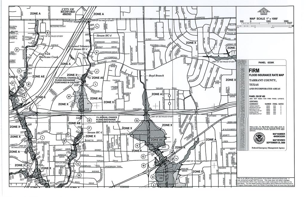
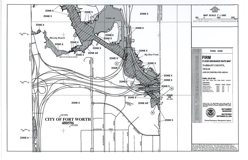
4 Preliminary Hydraulic Study on NTE Segment 2E 1. Introduction The purpose of this drainage study is to aid in the preparation of preliminary cost estimates and conceptual drainage plans for the proposed North Tarrant Expressway Segment 2E (NTE). Existing information was obtained from TxDOT as-built plans and previous drainage studies completed by TxDOT, the City of Euless, and the City of Bedford. See Appendix G for references. There are 10 existing outfalls along the NTE segment 2E project. The outfall naming convention follows that established in the TxDOT as-built plans. The drainage pattern is typically from north to south across the SH 183 project. Each outfall ultimately flows into the West Fork Trinity River south of the project. The drainage areas north of SH 183 are a mixture of urban development and residential neighborhoods. Big Bear Creek and Boyd Branch are the only FEMA floodplains within the project limits. Big Bear Creek is designated as Zone AE and Boyd Branch as Zone A. See Appendix A for FEMA maps. When SH 183 was first built, cross-drainage structures were built at each stream crossing along with storm drain systems that tie into these cross-drainage structures. Due to development along the corridor, many of these cross-drainage structures have been extended beyond the SH 183 ROW, and now resemble closed storm sewer systems. These systems were analyzed within the project ROW limits only, with assumptions made at the upstream and downstream ends. All drainage analysis and design is based on the ultimate proposed roadway design improvements. The proposed roadway improvements include the addition of tolled managed lanes for eastbound and westbound SH 183, new direct connectors to SH 360 and SH 97, and new profiles for the general purpose lanes. 2. Methodology & Analysis Hydrology: The drainage areas contributing to the NTE Segment 2E are shown in Appendix B. The drainage areas were determined from USGS Topographic Quad Maps and survey data along the corridor. The drainage design assumes a fully developed corridor, thus offsite drainage areas were assumed to have a C value of C values within the Right-of-Way (ROW) were TxDOT, Fort Worth District 1 AECOM
5 Preliminary Hydraulic Study on NTE Segment 2E assumed to be For small drainage areas (<200 acres) the rational method was used to calculate peak flows. The time of concentration (Tc) was calculated following the procedure outlined in Chapter 5 of the TxDOT Hydraulic Design Manual (HDM). The intensity was determined using coefficients for Tarrant County from the National Weather Service Technical Paper 40 (TP 40). For large, offsite drainage areas the peak flows were determined by using the program HEC- HMS. Drainage areas were delineated by using USGS 10ft contour maps and survey data along the corridor. Offsite Tc was determined from existing TxDOT as-builts or calculated using Chapter 5 of the HDM. See Figures 2 and 3 for drainage area maps. As-builts indicate a Tc of 10 minutes and an intensity of 6.6 in/hr was typically used in the design of the existing systems. This Tc equates to around a 5-yr event using TP-40 methodology. The NTE project requires a 50-year event be used in design. Because downstream conditions have been developed for the majority of segment 2E, increasing outfall capacity becomes difficult. Therefore detention will be required at several outfalls. Hydraulics: Existing systems that have been extended beyond the ROW were analyzed as closed storm sewer systems using TxDOT s WinStorm program. The required design frequency for general purpose and managed lane storm sewers is the 50-yr event. 3. Existing Outfall Structure Summary & Recommendations 3.1 Outfall J (Station 1307): General Info: The existing outfall is 1-6 x4 RCB that flows north to south across the project ROW. It is located at the intersection of the WB frontage road and Reliance Parkway on the upstream end, and the intersection of the EB frontage road and Wilshire Dr on the downstream end. The culvert has been extended beyond both ROW lines so there are no headwalls within the ROW. The existing system collects runoff from north of the ROW and storm drains along SH 183. TxDOT, Fort Worth District 2 AECOM
6 Preliminary Hydraulic Study on NTE Segment 2E Assessment: The existing system was analyzed as a storm sewer system from the upstream ROW to the downstream ROW. The contributing drainage area upstream is 70.0 acres. The C value for this area is 0.80 to allow for the ultimate build out. The time of concentration is calculated to be 55 minutes. On-site area is 15.0 acres with a C value of The resulting combined flows are 287 cfs for the 50-yr event and 313 cfs for the 100-yr event. The existing capacity of the 6x4 box culvert, using a slope of 0.62%, is 244 cfs. Therefore the existing system is undersized for the ultimate build out condition. Recommendations: It is recommended that detention storage be provided to help reduce the proposed peak flow due to an increase in impervious cover. This can be accomplished through in-line storage within the ROW, or with a detention pond outside the ROW. 3.2 Outfall K (Station 1334 Boyd Branch): General Info: The existing outfall is 2-10 x6 MBC that flows across the ROW to the south. The structure lies on the east side of the intersection of FM 157. Similar to the previous outfall, this MBC has been extended beyond both ROW lines. Multiple storm drain systems from SH 183 tie into the culvert including a 60 RCP that drains runoff from north of SH 183 along Sheppard Drive. This 60 RCP is referred to in the as-builts as system L. Assessment: The existing system was analyzed as a storm sewer system from the upstream ROW to the downstream ROW. The contributing drainage area is acres. To calculate peak flows the SCS Curve Number Method within HEC-HMS was used. A runoff curve number of 83 was used to reflect the industrial, residential, and park areas upstream. Tc was calculated to be 83 minutes. The resulting flows are 1,251 cfs for the 50-yr event and 1,409 cfs for the 100-yr event. The existing capacity of the 2-10x6 box culvert, using a slope of 0.32%, is 1,187 cfs. Therefore the existing system is undersized for the ultimate build out condition. Recommendations: It is recommended that detention storage be provided to help reduce the proposed peak flow to due to an increase in impervious cover. This can be accomplished through in-line storage TxDOT, Fort Worth District 3 AECOM
7 Preliminary Hydraulic Study on NTE Segment 2E within the ROW, or with a detention pond outside the ROW. During PS&E development it is anticipated that this stream crossing will require a floodplain study along with a CLOMR application with FEMA. 3.3 Outfall M (Station 1364): General Info: The existing outfall are 2-7 x3 MBC that flows across the ROW to the south. The structure is located approximately 300 feet east of Ector Drive. The upstream end is graded to flow into the curb inlets along the frontage road while the downstream end has a headwall that discharges into a channel. The existing system collects runoff from the drainage area north of the project as well as storm drains along SH 183. Assessment: The existing system was analyzed as a storm sewer system from the upstream ROW to the downstream ROW. The contributing drainage area upstream is 69.0 acres with a C value of 0.80 to allow for the ultimate build out. Tc was calculated to be 33 minutes. The onsite drainage area is 22.0 acres with a C value of The resulting combined flows are 433 cfs for the 50-yr event and 473 cfs for the 100-yr event. The existing capacity of the 2-7x3 box culvert, using a slope of 0.38%, is 304 cfs. Recommendations: The addition of 1-7x3 box culvert adjacent to the existing will raise capacity to 456 cfs, which is higher than the 50-yr event. A downstream drainage easement will be required to maintain the outfall and provide energy dissipation. 3.4 Outfall N (Station 1392): General Info: The existing outfall is 1-72 RCP that flows across the south ROW line. It is located approximately 700 ft east of Euless Main Street. The existing pipe extends across the south SH 183 ROW line and proceeds across SH 10 before outfalling into a ditch. The system collects runoff from the neighborhood north of SH 183 and storm drains along SH 183. Assessment: The existing system was analyzed as a storm sewer system from the upstream end of the 72 TxDOT, Fort Worth District 4 AECOM
8 Preliminary Hydraulic Study on NTE Segment 2E RCP to the downstream outfall south of SH 10. The contributing drainage area upstream is 13.9 acres with a C value of 0.80 to account for the ultimate build out. Tc was calculated to be 23 minutes. The onsite drainage area is 38.1 acres with a C value of The resulting combined flows are 337 cfs for the 50-yr event and 369 cfs for the 100-yr event. The proposed SH 183 profile is lower than the outfall flowline, thus part of the runoff from the existing drainage area will be carried east to Outfall Q in the proposed condition. This can be seen in Figure 3. The resulting proposed drainage area for outfall N is reduced to the SH 183 eastbound frontage road (16.1 acres). Proposed peak flows are 170 cfs for the 50-yr event and 186 cfs for the 100-yr event. Recommendations: The existing 72 RCP outfall is adequate in the proposed condition due to the reduced drainage area. 3.5 Outfall O (Station 1420): General Info: The existing outfall is 1-48 RCP that flows south across the ROW line. The outfall is located approximately 250 east of the intersection of FAA Blvd and East Euless Blvd. The system collects runoff from north of the ROW and storm drains along SH 183. An outfall ditch at the south ROW is intended to carry the 100-yr event minus the design event for the storm sewer system. This outfall ditch has been modified into a concrete flume with the addition of the Anthem Estates Subdivision. Assessment: The existing system was analyzed as a storm sewer system from the upstream end of the 48 RCP to the downstream ROW. The contributing drainage area upstream is 4.3 acres with a C value of 0.80 to account for the ultimate build out. Tc was calculated to be 35 mintues. The onsite drainage area is 22.7 acres with a C value of The resulting combined flows are 141 cfs for the 50-yr event and 154 cfs for the 100-yr event. The proposed SH 183 profile is lower than the outfall flowline, thus part of the runoff from the existing drainage area will be carried east to Outfall Q in the proposed condition. This can be seen in Figure 3. The resulting proposed drainage area for outfall O is reduced to the SH 183 TxDOT, Fort Worth District 5 AECOM
9 Preliminary Hydraulic Study on NTE Segment 2E eastbound frontage road (2.3 acres). Proposed peak flows are 24 cfs for the 50-yr event and 27 cfs for the 100-yr event. Recommendations: The existing 48 RCP outfall is adequate in the proposed condition due to the reduced drainage area. 3.6 Outfall P (FAA Blvd South): General Info: This system collects runoff from north of SH 183 between Bear Creek Parkway and SH 360, and runoff from along SH 183 and SH 360. The main trunk line runs along the EB SH 183 Frontage and proceeds along the SB SH 360 frontage road. The system then outfalls south of the FAA Boulevard/SH 360 intersection outside the limits of this project. Assessment: Part of the existing system was analyzed using WinStorm. The contributing drainage area upstream is 35.3 acres with a C value of 0.80 to account for the ultimate build out. Tc was calculated to be 27 minutes. The onsite drainage area is 15.4 acres with a C value of The resulting combined flows are 276 cfs for the 50-yr event and 302 cfs for the 100-yr event. The proposed SH 183 profile is lower than the laterals that cross SH 183. Therefore part of the runoff from the existing drainage area will be carried east to Outfall Q in the proposed condition. The existing 60 trunkline should be utilized where the proposed SH 183 EB frontage road ties into the existing frontage road. The resulting proposed drainage area for outfall P is reduced to the SH 183 eastbound frontage road (2.2 acres). Proposed peak flows are 23 cfs for the 50-yr event and 25 cfs for the 100-yr event. Recommendations: The existing trunk line along the SH 183 eastbound frontage road is adequate in the proposed condition due to the reduced drainage area. TxDOT, Fort Worth District 6 AECOM
10 Preliminary Hydraulic Study on NTE Segment 2E 3.7 Outfall Q (SH 360 North): General Info: The existing trunk line runs along the SH 360 southbound frontage road at the interchange with SH 183. The system collects runoff along SH 360 north of SH 183. The outfall is a 60 RCP that empties into a tributary to Blessing Branch east of SH 360. Assessment: Minimal changes are expected to the existing system so it was analyzed in WinStorm using asbuilts. Due to proposed roadway profile changes, runoff from Outfalls N, O, and P will be carried to this outfall. A proposed detention pond will be needed to reduce the peak flow from these additional areas to existing conditions. Recommendations: The existing trunk line is adequate due to the reduced drainage area. 3.8 Outfall R (Station 1475): General Info: This system collects runoff from the SH 183/SH 360 interchange and outfalls into a tributary to Big Bear Creek with a 78 RCP. Assessment: In the proposed conditions only direct connectors will be added to the drainage area. Therefore minimal changes are expected to the drainage system. Recommendations: No changes are expected to the outfall conditions. Drainage easement will be required downstream for channel grading and riprap. 3.9 Outfall S (Sta 1493): General Info: This system collects runoff from SH 183 at Amon Carter Blvd and outfalls into a tributary to Big Bear Creek with a 60 RCP. TxDOT, Fort Worth District 7 AECOM
11 Preliminary Hydraulic Study on NTE Segment 2E Assessment: In the proposed conditions only direct connectors will be added to the drainage area. Therefore minimal changes are expected to the drainage system. Recommendations: No changes are expected to the outfall conditions. Drainage easement will be required downstream for channel grading and riprap Outfall T (Big Bear Creek): General Info: Big Bear Creek runs southeast through the SH 183/SH97 interchange. Runoff from the interchange outfalls directly into the creek. Assessment: It is anticipated that columns from the proposed direct connects will be placed outside of the 100-yr floodplain or next to adjacent bridge columns, minimizing impacts to the water surface elevations. Therefore channel modifications to mitigate impacts are expected to be minimal, and a detailed HEC-RAS analysis was not performed. Recommendations: During PS&E development it is anticipated that this stream crossing will require a floodplain study along with a CLOMR application with FEMA. TxDOT, Fort Worth District 8 AECOM
12 Preliminary Hydraulic Study on NTE Segment 2E Appendix A Study Area FEMA Maps TxDOT, Fort Worth District AECOM
13
14
15 Preliminary Hydraulic Study on NTE Segment 2E Appendix B NTE Segment 2E Existing Drainage Area Maps TxDOT, Fort Worth District AECOM
16 T REV DATE BY DESCRIPTION BOYD BRANCH K AC LEGEND EXISTING OFFSITE DRAINAGE AREA EXISTING ONSITE DRAINAGE AREA FLOW DIRECTION STREAM FLOW EXISTING STORM DRAIN SYSTEM (FROM AS-BUILTS) EXISTING STORM DRAIN SYSTEM (ASSUMED) J 70.0 AC RELIANCE PARKWAY FM 157 INDUSTRIAL BLVD EXIST. 60" RCP M 69.0 AC 22.0 AC MATCHLINE - SHEET 2 WILSHIRE DR OUTFALL J EXIST. 1-6 X4 MBC 15.0 AC OUTFALL K EXIST X6 MBC 33.7 AC OUTFALL M EXIST. 2-7 X3 MBC ECTOR DR TO CYCLONE BRANCH AECOM Technical Services Inc THIS DOCUMENT IS RELEASED UNDER THE AUTHORITY OF: Scott C. Williams TEXAS REGISTRATION NO: DATE: $DATE$ NOT TO BE USED FOR BIDDING, CONSTRUCTION, OR PERMIT PURPOSES. NORTH TARRANT EXPRESS EXISTING DRAINAGE AREA EXHIBIT SCALE: 1"=500 SHEET 1 OF 3 $FILE$ FED. RD. DIV. NO. PROJECT NUMBER SHEET NO. STATE DISTRICT COUNTY TEXAS TARRANT JOB CONT SECT HIGHWAY NO SH 183 $DATE$ $TIME$
17 STATE REV DATE BY DESCRIPTION LEGEND EXISTING OFFSITE DRAINAGE AREA EXISTING ONSITE DRAINAGE AREA FLOW DIRECTION STREAM FLOW EXISTING STORM DRAIN SYSTEM (FROM AS-BUILTS) EXISTING STORM DRAIN SYSTEM (ASSUMED) MATCHLINE - SHEET 1 N 13.9 AC 38.1 AC O 4.3 AC P 35.3 AC MATCHLINE - SHEET AC EULESS MAIN ST OUTFALL N EXIST. 1-72" RCP 22.7 AC 15.4 AC OUTFALL O EXIST. 1-48" RCP AECOM Technical Services Inc THIS DOCUMENT IS RELEASED UNDER THE AUTHORITY OF: Scott C. Williams TEXAS REGISTRATION NO: DATE: $DATE$ OUTFALL P EXIST. 1-60" RCP NOT TO BE USED FOR BIDDING, CONSTRUCTION, OR PERMIT PURPOSES. NORTH TARRANT EXPRESS EXISTING DRAINAGE AREA EXHIBITS SCALE: 1"=500 SHEET 2 OF 3 $FILE$ FED. RD. DIV. NO. PROJECT NUMBER SHEET NO. DISTRICT COUNTY TEXAS TARRANT JOB CONT SECT HIGHWAY NO SH 183 $DATE$ $TIME$
18 FP FP FP TFP Valves )verhead Sign Piles Piles Area Under Construction Piles Piles Construction Area Under Construction Piles TFP Water TL TL TL TL FH Sign Pole Sign Pole Sign Water Water Water Water Sign Pole REV DATE BY DESCRIPTION BLESSING BRANCH LEGEND EXISTING OFFSITE DRAINAGE AREA EXISTING ONSITE DRAINAGE AREA FLOW DIRECTION STREAM FLOW EXISTING STORM DRAIN SYSTEM (FROM AS-BUILTS) EXISTING STORM DRAIN SYSTEM (ASSUMED) Q 41.3 AC OUTFALL Q EXIST. 1-60" RCP MATCHLINE - SHEET AC R 30.7 AC OUTFALL R EXIST. 1-78" RCP S OUTFALL S EXIST. 1-60" RCP 30.7 AC AECOM Technical Services Inc THIS DOCUMENT IS RELEASED UNDER THE AUTHORITY OF: Scott C. Williams TEXAS REGISTRATION NO: DATE: $DATE$ NOT TO BE USED FOR BIDDING, CONSTRUCTION, OR PERMIT PURPOSES. NORTH TARRANT EXPRESS EXISTING DRAINAGE AREA EXHIBIT SCALE: 1"=1000 SHEET 3 OF 3 $FILE$ FED. RD. DIV. NO. PROJECT NUMBER SHEET NO. STATE DISTRICT COUNTY TEXAS TARRANT JOB CONT SECT HIGHWAY NO SH 183 $DATE$ $TIME$
19 Preliminary Hydraulic Study on NTE Segment 2E Appendix C NTE Segment 2E Proposed Drainage Area Maps TxDOT, Fort Worth District AECOM
20 T REV DATE BY DESCRIPTION BOYD BRANCH K AC LEGEND EXISTING OFFSITE DRAINAGE AREA PROPOSED ONSITE DRAINAGE AREA FLOW DIRECTION STREAM FLOW EXISTING STORM DRAIN SYSTEM (FROM AS-BUILTS) EXISTING STORM DRAIN SYSTEM (ASSUMED) J 70.0 AC RELIANCE PARKWAY FM 157 INDUSTRIAL BLVD EXIST. 60" RCP M 69.0 AC 22.0 AC MATCHLINE - SHEET 2 WILSHIRE DR TO CYCLONE BRANCH OUTFALL J EXIST. 1-6 X4 MBC 15.0 AC OUTFALL K EXIST X6 MBC 33.7 AC OUTFALL M EXIST. 2-7 X3 MBC ECTOR DR AECOM Technical Services Inc THIS DOCUMENT IS RELEASED UNDER THE AUTHORITY OF: Scott C. Williams TEXAS REGISTRATION NO: DATE: $DATE$ NOT TO BE USED FOR BIDDING, CONSTRUCTION, OR PERMIT PURPOSES. NORTH TARRANT EXPRESS PROPOSED DRAINAGE AREA EXHIBIT SCALE: 1"=500 SHEET 1 OF 3 $FILE$ FED. RD. DIV. NO. PROJECT NUMBER SHEET NO. STATE DISTRICT COUNTY TEXAS TARRANT JOB CONT SECT HIGHWAY NO SH 183 $DATE$ $TIME$
21 STATE REV DATE BY DESCRIPTION LEGEND EXISTING OFFSITE DRAINAGE AREA PROPOSED ONSITE DRAINAGE AREA FLOW DIRECTION STREAM FLOW EXISTING STORM DRAIN SYSTEM (FROM AS-BUILTS) EXISTING STORM DRAIN SYSTEM (ASSUMED) MATCHLINE - SHEET 1 N 13.9 AC 49.9 AC O 4.3 AC P 35.3 AC MATCHLINE - SHEET AC 16.1 AC EULESS MAIN ST OUTFALL N EXIST. 1-72" RCP 2.3 AC 2.2 AC OUTFALL O EXIST. 1-48" RCP AECOM Technical Services Inc THIS DOCUMENT IS RELEASED UNDER THE AUTHORITY OF: Scott C. Williams TEXAS REGISTRATION NO: DATE: $DATE$ OUTFALL P EXIST. 1-60" RCP NOT TO BE USED FOR BIDDING, CONSTRUCTION, OR PERMIT PURPOSES. NORTH TARRANT EXPRESS PROPOSED DRAINAGE AREA EXHIBITS SCALE: 1"=500 SHEET 2 OF 3 $FILE$ FED. RD. DIV. NO. PROJECT NUMBER SHEET NO. DISTRICT COUNTY TEXAS TARRANT JOB CONT SECT HIGHWAY NO SH 183 $DATE$ $TIME$
22 FP FP FP TFP Valves )verhead Sign Piles Piles Area Under Construction Piles Piles Construction Area Under Construction Piles TFP Water TL TL TL TL FH Sign Pole Sign Pole Sign Water Water Water Water Sign Pole REV DATE BY DESCRIPTION BLESSING BRANCH LEGEND EXISTING OFFSITE DRAINAGE AREA PROPOSED ONSITE DRAINAGE AREA FLOW DIRECTION STREAM FLOW EXISTING STORM DRAIN SYSTEM (FROM AS-BUILTS) EXISTING STORM DRAIN SYSTEM (ASSUMED) Q 41.3 AC OUTFALL Q EXIST. 1-60" RCP MATCHLINE - SHEET AC PROPOSED DETENTION POND R AC OUTFALL R EXIST. 1-78" RCP S OUTFALL S EXIST. 1-60" RCP 26.4 AC AECOM Technical Services Inc THIS DOCUMENT IS RELEASED UNDER THE AUTHORITY OF: Scott C. Williams TEXAS REGISTRATION NO: DATE: $DATE$ NOT TO BE USED FOR BIDDING, CONSTRUCTION, OR PERMIT PURPOSES. NORTH TARRANT EXPRESS EXISTING DRAINAGE AREA EXHIBIT SCALE: 1"=1000 SHEET 3 OF 3 $FILE$ FED. RD. DIV. NO. PROJECT NUMBER SHEET NO. STATE DISTRICT COUNTY TEXAS TARRANT JOB CONT SECT HIGHWAY NO SH 183 $DATE$ $TIME$
23 Preliminary Hydraulic Study on NTE Segment 2E Appendix D NTE Segment 2E Peak Flow Summary TxDOT, Fort Worth District AECOM
24 Outfall Outfall Station Existing Outfall Structure Existing Drainage Area Tc I 50 I 100 Pervious Existing Area Existing Impervious Area Summary of Onsite 100-yr Peak Flows Existing % Impervious Existing C Value Proposed Existing Existing Q Q 100 Drainage 50 Area Proposed Pervious Area Proposed Impervious Area acres min in/hr in/hr acres acres cfs cfs acres acres acres cfs cfs J 'x4' RCB % % K 'x6' MBC % % M 'x3' MBC % % N " RCP % % O " RCP % % P 1-60" RCP % % Q 1-60" RCP % % R " RCP % % S " RCP % % Proposed % Impervious Proposed C Value Proposed Q 50 Proposed Q 100
25 Outfall Outfall Station Existing Outfall Structure Existing Drainage Area Hydrologic Method Summary of Offsite 100-yr Peak Flows Tc I 50 I 100 P 50 P 100 Curve Runoff Number Existing C Value Existing Q 50 Existing Q 100 acres min in/hr in/hr in in cfs cfs J 'x4' RCB 70.0 Rational N/A N/A N/A K 'x6' MBC SCS 83 N/A N/A M 'x3' MBC 69.0 Rational N/A N/A N/A N " RCP 13.9 Rational N/A N/A N/A O " RCP 4.3 Rational N/A N/A N/A P 1-60" RCP 35.3 Rational N/A N/A N/A Q 1-60" RCP 30.7 Rational N/A N/A N/A
26 Preliminary Hydraulic Study on NTE Segment 2E Appendix E TxDOT WinStorm Calculations TxDOT, Fort Worth District AECOM
27 System J.txt WinStorm (STORM DRAIN DESIGN) Version 3.05, Jan. 25, /15/ :25:05 PM PROJECT NAME : NTE 2E JOB NUMBER : PROJECT DESCRIPTION : System J-Existing 6'x4' RBC at Reliance Pkwy DESIGN FREQUENCY : 50 Years ANALYSYS FREQUENCY : 100 Years MEASUREMENT UNITS: ENGLISH OUTPUT FOR DESIGN FREQUENCY of: 50 Years =========================================== Runoff Computation for Design Frequency. ============================================================================= ID C Value Area Tc Tc Used Intensity Supply Q Total Q (acre) (min) (min) (in/hr) (cfs) (cfs) J J Cumulative Junction Discharge Computations ================================================================================= Node Node Weighted Cumulat. Cumulat. Intens. User Additional Total I.D. Type C-Value Dr.Area Tc Supply Q Q in Node Disch. (acres) (min) (in/hr) cfs) (cfs) (cfs) J-1 CircMh J-2 CircMh OUT Outlt Conveyance Configuration Data Run# Node I.D. Flowline Elev. US DS US DS Shape # Span Rise Length Slope n_value (ft) (ft) (ft) (ft) (ft) (%) 1 J-1 J Box J-2 OUT Box Conveyance Hydraulic Computations. Tailwater = (ft) Hydraulic Gradeline Depth Velocity Junc Run# US Elev DS Elev Fr.Slope Unif. Actual Unif. Actual Q Cap Loss (ft) (ft) (%) (ft) (ft) (f/s) (f/s) (cfs) (cfs) (ft) OUTPUT FOR ANALYSYS FREQUENCY of: 100 Years ============================================= Runoff Computation for Analysis Frequency. ============================================================================= ID C Value Area Tc Tc Used Intensity Supply Q Total Q (acre) (min) (min) (in/hr) (cfs) (cfs) J J Page 1
28 System J.txt Cumulative Junction Discharge Computations ================================================================================= Node Node Weighted Cumulat. Cumulat. Intens. User Additional Total I.D. Type C-Value Dr.Area Tc Supply Q Q in Node Disch. (acres) (min) (in/hr) cfs) (cfs) (cfs) J-1 CircMh J-2 CircMh OUT Outlt Conveyance Configuration Data Run# Node I.D. Flowline Elev. US DS US DS Shape # Span Rise Length Slope n_value (ft) (ft) (ft) (ft) (ft) (%) 1 J-1 J Box J-2 OUT Box Conveyance Hydraulic Computations. Tailwater = (ft) Hydraulic Gradeline Depth Velocity Junc Run# US Elev DS Elev Fr.Slope Unif. Actual Unif. Actual Q Cap Loss (ft) (ft) (%) (ft) (ft) (f/s) (f/s) (cfs) (cfs) (ft) ===================================END============================================ NORMAL TERMINATION OF WINSTORM. Warning Messages for current project: Runoff Frequency of: 50 Years Run# 2 Insufficient capacity. Runoff Frequency of: 100 Years Run# 2 Insufficient capacity. Run# 1 Insufficient capacity. Page 2
29 System K.txt WinStorm (STORM DRAIN DESIGN) Version 3.05, Jan. 25, /14/2009 9:15:08 AM PROJECT NAME : NTE 2E JOB NUMBER : PROJECT DESCRIPTION : System K-Existing 2-10'x6' MBC at FM 157 DESIGN FREQUENCY : 50 Years ANALYSYS FREQUENCY : 100 Years MEASUREMENT UNITS: ENGLISH OUTPUT FOR DESIGN FREQUENCY of: 50 Years =========================================== Runoff Computation for Design Frequency. ============================================================================= ID C Value Area Tc Tc Used Intensity Supply Q Total Q (acre) (min) (min) (in/hr) (cfs) (cfs) K Cumulative Junction Discharge Computations ================================================================================= Node Node Weighted Cumulat. Cumulat. Intens. User Additional Total I.D. Type C-Value Dr.Area Tc Supply Q Q in Node Disch. (acres) (min) (in/hr) cfs) (cfs) (cfs) K-2 CircMh OUT Outlt Conveyance Configuration Data Run# Node I.D. Flowline Elev. US DS US DS Shape # Span Rise Length Slope n_value (ft) (ft) (ft) (ft) (ft) (%) 2 K-2 OUT Box Conveyance Hydraulic Computations. Tailwater = (ft) Hydraulic Gradeline Depth Velocity Junc Run# US Elev DS Elev Fr.Slope Unif. Actual Unif. Actual Q Cap Loss (ft) (ft) (%) (ft) (ft) (f/s) (f/s) (cfs) (cfs) (ft) OUTPUT FOR ANALYSYS FREQUENCY of: 100 Years ============================================= Runoff Computation for Analysis Frequency. ============================================================================= ID C Value Area Tc Tc Used Intensity Supply Q Total Q (acre) (min) (min) (in/hr) (cfs) (cfs) K Cumulative Junction Discharge Computations ================================================================================= Node Node Weighted Cumulat. Cumulat. Intens. User Additional Total I.D. Type C-Value Dr.Area Tc Supply Q Q in Node Disch. (acres) (min) (in/hr) cfs) (cfs) (cfs) Page 1
30 System K.txt K-2 CircMh OUT Outlt Conveyance Configuration Data Run# Node I.D. Flowline Elev. US DS US DS Shape # Span Rise Length Slope n_value (ft) (ft) (ft) (ft) (ft) (%) 2 K-2 OUT Box Conveyance Hydraulic Computations. Tailwater = (ft) Hydraulic Gradeline Depth Velocity Junc Run# US Elev DS Elev Fr.Slope Unif. Actual Unif. Actual Q Cap Loss (ft) (ft) (%) (ft) (ft) (f/s) (f/s) (cfs) (cfs) (ft) ===================================END============================================ NORMAL TERMINATION OF WINSTORM. Warning Messages for current project: Runoff Frequency of: 50 Years Run# 2 Insufficient capacity. Runoff Frequency of: 100 Years Run# 2 Insufficient capacity. Page 2
31 System M.txt WinStorm (STORM DRAIN DESIGN) Version 3.05, Jan. 25, /15/ :06:30 AM PROJECT NAME : NTE 2E JOB NUMBER : PROJECT DESCRIPTION : System M-Existing 2-7'x3' MBC east of Ector Dr DESIGN FREQUENCY : 50 Years ANALYSYS FREQUENCY : 100 Years MEASUREMENT UNITS: ENGLISH OUTPUT FOR DESIGN FREQUENCY of: 50 Years =========================================== Runoff Computation for Design Frequency. ============================================================================= ID C Value Area Tc Tc Used Intensity Supply Q Total Q (acre) (min) (min) (in/hr) (cfs) (cfs) M M Cumulative Junction Discharge Computations ================================================================================= Node Node Weighted Cumulat. Cumulat. Intens. User Additional Total I.D. Type C-Value Dr.Area Tc Supply Q Q in Node Disch. (acres) (min) (in/hr) cfs) (cfs) (cfs) M-1 CircMh M-2 CircMh OUT Outlt Conveyance Configuration Data Run# Node I.D. Flowline Elev. US DS US DS Shape # Span Rise Length Slope n_value (ft) (ft) (ft) (ft) (ft) (%) 1 M-1 M Box M-2 OUT Box Conveyance Hydraulic Computations. Tailwater = (ft) Hydraulic Gradeline Depth Velocity Junc Run# US Elev DS Elev Fr.Slope Unif. Actual Unif. Actual Q Cap Loss (ft) (ft) (%) (ft) (ft) (f/s) (f/s) (cfs) (cfs) (ft) OUTPUT FOR ANALYSYS FREQUENCY of: 100 Years ============================================= Runoff Computation for Analysis Frequency. ============================================================================= ID C Value Area Tc Tc Used Intensity Supply Q Total Q (acre) (min) (min) (in/hr) (cfs) (cfs) M M Page 1
32 System M.txt Cumulative Junction Discharge Computations ================================================================================= Node Node Weighted Cumulat. Cumulat. Intens. User Additional Total I.D. Type C-Value Dr.Area Tc Supply Q Q in Node Disch. (acres) (min) (in/hr) cfs) (cfs) (cfs) M-1 CircMh M-2 CircMh OUT Outlt Conveyance Configuration Data Run# Node I.D. Flowline Elev. US DS US DS Shape # Span Rise Length Slope n_value (ft) (ft) (ft) (ft) (ft) (%) 1 M-1 M Box M-2 OUT Box Conveyance Hydraulic Computations. Tailwater = (ft) Hydraulic Gradeline Depth Velocity Junc Run# US Elev DS Elev Fr.Slope Unif. Actual Unif. Actual Q Cap Loss (ft) (ft) (%) (ft) (ft) (f/s) (f/s) (cfs) (cfs) (ft) ===================================END============================================ NORMAL TERMINATION OF WINSTORM. Warning Messages for current project: Runoff Frequency of: 50 Years Run# 2 Insufficient capacity. Upstream hydraulic gradeline exceeds critical elevation at node Id= M-2 Run# 1 Insufficient capacity. Upstream hydraulic gradeline exceeds critical elevation at node Id= M-1 Runoff Frequency of: 100 Years Run# 2 Insufficient capacity. Upstream hydraulic gradeline exceeds critical elevation at node Id= M-2 Run# 1 Insufficient capacity. Upstream hydraulic gradeline exceeds critical elevation at node Id= M-1 Page 2
33 System N.txt WinStorm (STORM DRAIN DESIGN) Version 3.05, Jan. 25, /15/ :12:09 AM PROJECT NAME : NTE 2E JOB NUMBER : PROJECT DESCRIPTION : System N-Existing 72" RCP east of Euless Main St DESIGN FREQUENCY : 50 Years ANALYSYS FREQUENCY : 100 Years MEASUREMENT UNITS: ENGLISH OUTPUT FOR DESIGN FREQUENCY of: 50 Years =========================================== Runoff Computation for Design Frequency. ============================================================================= ID C Value Area Tc Tc Used Intensity Supply Q Total Q (acre) (min) (min) (in/hr) (cfs) (cfs) N N Cumulative Junction Discharge Computations ================================================================================= Node Node Weighted Cumulat. Cumulat. Intens. User Additional Total I.D. Type C-Value Dr.Area Tc Supply Q Q in Node Disch. (acres) (min) (in/hr) cfs) (cfs) (cfs) N-1 CircMh N-2 CircMh OUT Outlt Conveyance Configuration Data Run# Node I.D. Flowline Elev. US DS US DS Shape # Span Rise Length Slope n_value (ft) (ft) (ft) (ft) (ft) (%) 1 N-1 N Circ N-2 OUT Circ Conveyance Hydraulic Computations. Tailwater = (ft) Hydraulic Gradeline Depth Velocity Junc Run# US Elev DS Elev Fr.Slope Unif. Actual Unif. Actual Q Cap Loss (ft) (ft) (%) (ft) (ft) (f/s) (f/s) (cfs) (cfs) (ft) 1* * OUTPUT FOR ANALYSYS FREQUENCY of: 100 Years ============================================= Runoff Computation for Analysis Frequency. ============================================================================= ID C Value Area Tc Tc Used Intensity Supply Q Total Q (acre) (min) (min) (in/hr) (cfs) (cfs) N N Page 1
34 System N.txt Cumulative Junction Discharge Computations ================================================================================= Node Node Weighted Cumulat. Cumulat. Intens. User Additional Total I.D. Type C-Value Dr.Area Tc Supply Q Q in Node Disch. (acres) (min) (in/hr) cfs) (cfs) (cfs) N-1 CircMh N-2 CircMh OUT Outlt Conveyance Configuration Data Run# Node I.D. Flowline Elev. US DS US DS Shape # Span Rise Length Slope n_value (ft) (ft) (ft) (ft) (ft) (%) 1 N-1 N Circ N-2 OUT Circ Conveyance Hydraulic Computations. Tailwater = (ft) Hydraulic Gradeline Depth Velocity Junc Run# US Elev DS Elev Fr.Slope Unif. Actual Unif. Actual Q Cap Loss (ft) (ft) (%) (ft) (ft) (f/s) (f/s) (cfs) (cfs) (ft) 1* ===================================END============================================ * Super critical flow. NORMAL TERMINATION OF WINSTORM. Warning Messages for current project: Runoff Frequency of: 50 Years Upstream hydraulic gradeline exceeds critical elevation at node Id= N-2 Upstream hydraulic gradeline exceeds critical elevation at node Id= N-1 Runoff Frequency of: 100 Years Run# 2 Insufficient capacity. Upstream hydraulic gradeline exceeds critical elevation at node Id= N-2 Upstream hydraulic gradeline exceeds critical elevation at node Id= N-1 Page 2
35 System O.txt WinStorm (STORM DRAIN DESIGN) Version 3.05, Jan. 25, /14/2009 9:16:08 AM PROJECT NAME : NTE 2E JOB NUMBER : PROJECT DESCRIPTION : System O-Existing 48" RCP west of Bear Creek Pkwy DESIGN FREQUENCY : 50 Years ANALYSYS FREQUENCY : 100 Years MEASUREMENT UNITS: ENGLISH OUTPUT FOR DESIGN FREQUENCY of: 50 Years =========================================== Runoff Computation for Design Frequency. ============================================================================= ID C Value Area Tc Tc Used Intensity Supply Q Total Q (acre) (min) (min) (in/hr) (cfs) (cfs) O O Cumulative Junction Discharge Computations ================================================================================= Node Node Weighted Cumulat. Cumulat. Intens. User Additional Total I.D. Type C-Value Dr.Area Tc Supply Q Q in Node Disch. (acres) (min) (in/hr) cfs) (cfs) (cfs) O-1 CircMh O-2 CircMh OUT Outlt Conveyance Configuration Data Run# Node I.D. Flowline Elev. US DS US DS Shape # Span Rise Length Slope n_value (ft) (ft) (ft) (ft) (ft) (%) 1 O-1 O Circ O-2 OUT Circ Conveyance Hydraulic Computations. Tailwater = (ft) Hydraulic Gradeline Depth Velocity Junc Run# US Elev DS Elev Fr.Slope Unif. Actual Unif. Actual Q Cap Loss (ft) (ft) (%) (ft) (ft) (f/s) (f/s) (cfs) (cfs) (ft) 1* OUTPUT FOR ANALYSYS FREQUENCY of: 100 Years ============================================= Runoff Computation for Analysis Frequency. ============================================================================= ID C Value Area Tc Tc Used Intensity Supply Q Total Q (acre) (min) (min) (in/hr) (cfs) (cfs) O O Page 1
36 System O.txt Cumulative Junction Discharge Computations ================================================================================= Node Node Weighted Cumulat. Cumulat. Intens. User Additional Total I.D. Type C-Value Dr.Area Tc Supply Q Q in Node Disch. (acres) (min) (in/hr) cfs) (cfs) (cfs) O-1 CircMh O-2 CircMh OUT Outlt Conveyance Configuration Data Run# Node I.D. Flowline Elev. US DS US DS Shape # Span Rise Length Slope n_value (ft) (ft) (ft) (ft) (ft) (%) 1 O-1 O Circ O-2 OUT Circ Conveyance Hydraulic Computations. Tailwater = (ft) Hydraulic Gradeline Depth Velocity Junc Run# US Elev DS Elev Fr.Slope Unif. Actual Unif. Actual Q Cap Loss (ft) (ft) (%) (ft) (ft) (f/s) (f/s) (cfs) (cfs) (ft) 1* ===================================END============================================ * Super critical flow. NORMAL TERMINATION OF WINSTORM. Warning Messages for current project: Runoff Frequency of: 50 Years Tailwater set to uniform depth elevation = (ft) Run# 2 Insufficient capacity. Upstream hydraulic gradeline exceeds critical elevation at node Id= O-2 Upstream hydraulic gradeline exceeds critical elevation at node Id= O-1 Runoff Frequency of: 100 Years Tailwater set to uniform depth elevation = (ft) Run# 2 Insufficient capacity. Upstream hydraulic gradeline exceeds critical elevation at node Id= O-2 Upstream hydraulic gradeline exceeds critical elevation at node Id= O-1 Page 2
37 System P.txt WinStorm (STORM DRAIN DESIGN) Version 3.05, Jan. 25, /15/ :17:58 AM PROJECT NAME : NTE 2E JOB NUMBER : PROJECT DESCRIPTION : System P-Existing 60" RCP along SH 183 EBFR DESIGN FREQUENCY : 50 Years ANALYSYS FREQUENCY : 100 Years MEASUREMENT UNITS: ENGLISH OUTPUT FOR DESIGN FREQUENCY of: 50 Years =========================================== Runoff Computation for Design Frequency. ============================================================================= ID C Value Area Tc Tc Used Intensity Supply Q Total Q (acre) (min) (min) (in/hr) (cfs) (cfs) P P Cumulative Junction Discharge Computations ================================================================================= Node Node Weighted Cumulat. Cumulat. Intens. User Additional Total I.D. Type C-Value Dr.Area Tc Supply Q Q in Node Disch. (acres) (min) (in/hr) cfs) (cfs) (cfs) P-1 CircMh P-2 CircMh OUT Outlt Conveyance Configuration Data Run# Node I.D. Flowline Elev. US DS US DS Shape # Span Rise Length Slope n_value (ft) (ft) (ft) (ft) (ft) (%) 1 P-1 P Circ P-2 OUT Circ Conveyance Hydraulic Computations. Tailwater = (ft) Hydraulic Gradeline Depth Velocity Junc Run# US Elev DS Elev Fr.Slope Unif. Actual Unif. Actual Q Cap Loss (ft) (ft) (%) (ft) (ft) (f/s) (f/s) (cfs) (cfs) (ft) OUTPUT FOR ANALYSYS FREQUENCY of: 100 Years ============================================= Runoff Computation for Analysis Frequency. ============================================================================= ID C Value Area Tc Tc Used Intensity Supply Q Total Q (acre) (min) (min) (in/hr) (cfs) (cfs) P P Page 1
38 System P.txt Cumulative Junction Discharge Computations ================================================================================= Node Node Weighted Cumulat. Cumulat. Intens. User Additional Total I.D. Type C-Value Dr.Area Tc Supply Q Q in Node Disch. (acres) (min) (in/hr) cfs) (cfs) (cfs) P-1 CircMh P-2 CircMh OUT Outlt Conveyance Configuration Data Run# Node I.D. Flowline Elev. US DS US DS Shape # Span Rise Length Slope n_value (ft) (ft) (ft) (ft) (ft) (%) 1 P-1 P Circ P-2 OUT Circ Conveyance Hydraulic Computations. Tailwater = (ft) Hydraulic Gradeline Depth Velocity Junc Run# US Elev DS Elev Fr.Slope Unif. Actual Unif. Actual Q Cap Loss (ft) (ft) (%) (ft) (ft) (f/s) (f/s) (cfs) (cfs) (ft) ===================================END============================================ NORMAL TERMINATION OF WINSTORM. Warning Messages for current project: Runoff Frequency of: 50 Years Run# 2 Insufficient capacity. Run# 1 Insufficient capacity. Runoff Frequency of: 100 Years Run# 2 Insufficient capacity. Run# 1 Insufficient capacity. Page 2
39 System Q.txt WinStorm (STORM DRAIN DESIGN) Version 3.05, Jan. 25, /14/2009 9:16:41 AM PROJECT NAME : NTE 2E JOB NUMBER : PROJECT DESCRIPTION : System Q-Existing 60" RCP east of SH 360 DESIGN FREQUENCY : 50 Years ANALYSYS FREQUENCY : 100 Years MEASUREMENT UNITS: ENGLISH OUTPUT FOR DESIGN FREQUENCY of: 50 Years =========================================== Runoff Computation for Design Frequency. ============================================================================= ID C Value Area Tc Tc Used Intensity Supply Q Total Q (acre) (min) (min) (in/hr) (cfs) (cfs) Q Q Q Q Q Cumulative Junction Discharge Computations ================================================================================= Node Node Weighted Cumulat. Cumulat. Intens. User Additional Total I.D. Type C-Value Dr.Area Tc Supply Q Q in Node Disch. (acres) (min) (in/hr) cfs) (cfs) (cfs) Q-1 CircMh Q-2 CircMh Q-3 CircMh Q-4 CircMh Q-5 CircMh OUT Outlt Conveyance Configuration Data Run# Node I.D. Flowline Elev. US DS US DS Shape # Span Rise Length Slope n_value (ft) (ft) (ft) (ft) (ft) (%) 1 Q-1 Q Circ Q-2 Q Circ Q-3 Q Circ Q-4 Q Circ Q-5 OUT Circ Conveyance Hydraulic Computations. Tailwater = (ft) Hydraulic Gradeline Depth Velocity Junc Run# US Elev DS Elev Fr.Slope Unif. Actual Unif. Actual Q Cap Loss (ft) (ft) (%) (ft) (ft) (f/s) (f/s) (cfs) (cfs) (ft) 1* * * * * OUTPUT FOR ANALYSYS FREQUENCY of: 100 Years ============================================= Page 1
40 System Q.txt Runoff Computation for Analysis Frequency. ============================================================================= ID C Value Area Tc Tc Used Intensity Supply Q Total Q (acre) (min) (min) (in/hr) (cfs) (cfs) Q Q Q Q Q Cumulative Junction Discharge Computations ================================================================================= Node Node Weighted Cumulat. Cumulat. Intens. User Additional Total I.D. Type C-Value Dr.Area Tc Supply Q Q in Node Disch. (acres) (min) (in/hr) cfs) (cfs) (cfs) Q-1 CircMh Q-2 CircMh Q-3 CircMh Q-4 CircMh Q-5 CircMh OUT Outlt Conveyance Configuration Data Run# Node I.D. Flowline Elev. US DS US DS Shape # Span Rise Length Slope n_value (ft) (ft) (ft) (ft) (ft) (%) 1 Q-1 Q Circ Q-2 Q Circ Q-3 Q Circ Q-4 Q Circ Q-5 OUT Circ Conveyance Hydraulic Computations. Tailwater = (ft) Hydraulic Gradeline Depth Velocity Junc Run# US Elev DS Elev Fr.Slope Unif. Actual Unif. Actual Q Cap Loss (ft) (ft) (%) (ft) (ft) (f/s) (f/s) (cfs) (cfs) (ft) * * ===================================END============================================ * Super critical flow. NORMAL TERMINATION OF WINSTORM. Warning Messages for current project: Runoff Frequency of: 50 Years Upstream hydraulic gradeline exceeds critical elevation at node Id= Q-5 Run# 4 Insufficient capacity. Upstream hydraulic gradeline exceeds critical elevation at node Id= Q-4 Run# 3 Insufficient capacity. Upstream hydraulic gradeline exceeds critical elevation at node Id= Q-3 Run# 1 Insufficient capacity. Runoff Frequency of: 100 Years Run# 5 Insufficient capacity. Upstream hydraulic gradeline exceeds critical elevation at node Id= Q-5 Run# 4 Insufficient capacity. Page 2
APPENDIX B DRAINAGE REPORT
 APPENDIX B DRAINAGE REPORT B-1 South Lamar Blvd. Transportation Corridor Study Drainage Report Prepared for: City of Austin and HDR, Inc. Prepared by: and Services, Inc. Final 07-09-2015 Michael C. Meriwether,
ARTICLE 5 (PART 2) DETENTION VOLUME EXAMPLE PROBLEMS
 DETENTION VOLUME EXAMPLE PROBLEMS") ARTICLE 5 (PART 2) DETENTION VOLUME EXAMPLE PROBLEMS Example 5.7 Simple (Detention Nomograph) Example 5.8 Offsite and Unrestricted Areas (HEC-HMS) Example 5.9 Ponds in Series w/ Tailwater (HEC-HMS) Example
ARTICLE 5 (PART 2) DETENTION VOLUME EXAMPLE PROBLEMS Example 5.7 Simple (Detention Nomograph) Example 5.8 Offsite and Unrestricted Areas (HEC-HMS) Example 5.9 Ponds in Series w/ Tailwater (HEC-HMS) Example
Chapter 10 - Sacramento Method Examples
 Chapter 10 Sacramento Method Examples Introduction Overview This chapter presents two example problems to demonstrate the use of the Sacramento method. These example problems use the SACPRE and HEC-1 computer
CITY OF CAPE CORAL STORMWATER MASTER PLAN PHASE II - PART 1 BASINS 4, 10, & 14 SUB-BASIN DRAINAGE IMPROVEMENTS HYDRAULIC ANALYSIS SUMMARY
 CITY OF CAPE CORAL STORMWATER MASTER PLAN PHASE II - PART 1 BASINS 4, 10, & 14 SUB-BASIN DRAINAGE IMPROVEMENTS HYDRAULIC ANALYSIS SUMMARY Cape Coral, FL Prepared for: The City of Cape Coral Public Works
STORMWATER REPORT FRITO LAY SUBDIVISION NO. 3
 STORMWATER REPORT FRITO LAY SUBDIVISION NO. 3 May 2018 STORMWATER REPORT I. Subdivision Data a. The parcel is adjacent to the existing Frito Lay property in Topeka; and the subject plat application encompasses
Stormwater Capacity Analysis for Westover Branch Watershed
 Stormwater Capacity Analysis for Westover Branch Watershed Pimmit Run Little Pimmit Run, Mainstem Stohman's Run Gulf Branch Pimmit Run Tributary Little Pimmit Run, W. Branch Little Pimmit Run, E. Branch
Drainage Analysis. Appendix F
 Drainage Analysis Appendix F Golden View Drive Elizabeth Street LMORE CREEK Ricky Road Rabbit Creek Road LITTLE RABBIT CREEK East 156th Avenue MOA Project #10-026 Golden View Drive Intersection
City of Thornton Attn: Tim Semones Development Engineeering 9500 Civic Center Dr. Thornton, CO 80229
 Development Engineering Land Surveying Construction Administration District Services October 20, 2017 City of Thornton Attn: Tim Semones Development Engineeering 9500 Civic Center Dr. Thornton, CO 80229
Hydrology Study Report
 Hafeez Consulting www.hafeezconsulting.com Civil/ Structural Engineering, Design & Construction 1451 S. Hacienda St. Anaheim CA 92804 (714) 225-4565 Fax (714)917-2977 engineer@hafeezconsulting.com Hydrology
DRAINAGE REPORT FOR THORNTON SELF STORAGE THORNTON, COLORADO
 DRAINAGE REPORT FOR THORNTON SELF STORAGE THORNTON, COLORADO Prepared by: Bowman Consulting 603 Park Point Dr. Suite 100 Golden, CO 80401 (303)-801-2900 June 29, 2015 Revised August 14, 2015 CERTIFICATE
UTILITY REPORT FOR THORNTON SELF STORAGE THORNTON, COLORADO
 UTILITY REPORT FOR THORNTON SELF STORAGE THORNTON, COLORADO Prepared by: Bowman Consulting 63 Park Point Dr. Suite 1 Golden, CO 841 (33)-81-29 June 29, 215 Revised August 14, 215 Revised September 3, 215
PENNSYLVANIA DEPARTMENT OF TRANSPORTATION ENGINEERING DISTRICT 3-0
 PENNSYLVANIA DEPARTMENT OF TRANSPORTATION ENGINEERING DISTRICT 3-0 LYCOMING COUNTY S.R.15, SECTION C41 FINAL HYDROLOGIC AND HYDRAULIC REPORT STEAM VALLEY RUN STREAM RELOCATION DATE: June, 2006 REVISED:
Section 4: Model Development and Application
 Section 4: Model Development and Application The hydrologic model for the Wissahickon Act 167 study was built using GIS layers of land use, hydrologic soil groups, terrain and orthophotography. Within
PRELIMINARY CULVERT ANALYSIS REPORT FOR CULVERT NO. 008-C OREGON AVENUE OVER PINEHURST CREEK
 PRELIMINARY CULVERT ANALYSIS REPORT FOR CULVERT NO. 008-C OREGON AVENUE OVER PINEHURST CREEK Prepared for The District of Columbia Department of Transportation Washington, D.C. Prepared by Parsons Transportation
Chapter 5 CALIBRATION AND VERIFICATION
 Chapter 5 CALIBRATION AND VERIFICATION This chapter contains the calibration procedure and data used for the LSC existing conditions model. The goal of the calibration effort was to develop a hydraulic
LOCATED IN INDIAN RIVER COUNTY PREPARED FOR S.J.R.W.M.D. AND F.W.C.D. DECEMBER, 2003 Updated 2007 Updated May 2014 PREPARED BY
 FELLSMERE WATER CONTROL DISTRICT EAST MASTER DRAINAGE PLAN AND STORMWATER HYDROLOGIC ANALYSIS OF THE GRAVITY DRAINAGE SYSTEM LOCATED BETWEEN THE EAST BOUNDARY, LATERAL U, THE MAIN CANAL, AND DITCH 24 LOCATED
BRANDON LAKES AVENUE PRE AND POST CONDITIONS DRAINAGE REPORT
 BRANDON LAKES AVENUE PRE AND POST CONDITIONS DRAINAGE REPORT Hillsborough County Public Works County Center, 22nd Floor 601 E. Kennedy Blvd. Tampa, FL 33602 BRANDON LAKES AVENUE DRAINAGE IMPROVEMENTS Capital
Hydrology and Hydraulics Design Report. Background Summary
 To: National Park Services Montezuma Castle National Monument Richard Goepfrich, Facility Manager From: Multicultural Technical Engineers Date: Tuesday - February 13, 2018 Subject: 30% Hydrology and Hydraulics
STREUVER FIDELCO CAPPELLI, LLC YONKERS DOWNTOWN DEVELOPMENT PHASE 1. DRAFT ENVIRONMENTAL IMPACT STATEMENT For: PALISADES POINT
 STREUVER FIDELCO CAPPELLI, LLC YONKERS DOWNTOWN DEVELOPMENT PHASE 1 DRAFT ENVIRONMENTAL IMPACT STATEMENT For: PALISADES POINT Prepared by: PAULUS, SOKOLOWSKI & SARTOR STORMWATER MANAGEMENT 1. Methodology
WATER MANAGEMENT REPORT FOR PAGE ESTATES
 WATER MANAGEMENT REPORT FOR PAGE ESTATES SLB Consulting of SW Florida, LLC PO Box 2826 Bonita Springs, FL. 34133 Phone: 239-948-9566 sandra@slbconsult.com C.O.A. # 25395 September 1, 2014 Sandra L. Bottcher
September 6, City of Thornton 9500 Civic Center Drive Thornton, CO (303) RE: Maverik Thornton, CO - Drainage Report
 RE: Maverik Thornton, CO - Drainage Report") September 6, 2016 City of Thornton 9500 Civic Center Drive Thornton, CO 80229 (303) 538-7295 RE: Maverik Thornton, CO - Drainage Report As per your request, we are submitting to you the drainage report
September 6, 2016 City of Thornton 9500 Civic Center Drive Thornton, CO 80229 (303) 538-7295 RE: Maverik Thornton, CO - Drainage Report As per your request, we are submitting to you the drainage report
YELLOWSTONE RIVER FLOOD STUDY REPORT TEXT
 YELLOWSTONE RIVER FLOOD STUDY REPORT TEXT TECHNICAL REPORT Prepared for: City of Livingston 411 East Callender Livingston, MT 59047 Prepared by: Clear Creek Hydrology, Inc. 1627 West Main Street, #294
INFLOW DESIGN FLOOD CONTROL SYSTEM PLAN 40 C.F.R. PART PLANT YATES ASH POND 2 (AP-2) GEORGIA POWER COMPANY
 GEORGIA POWER COMPANY") INFLOW DESIGN FLOOD CONTROL SYSTEM PLAN 40 C.F.R. PART 257.82 PLANT YATES ASH POND 2 (AP-2) GEORGIA POWER COMPANY EPA s Disposal of Coal Combustion Residuals from Electric Utilities Final Rule (40 C.F.R.
INFLOW DESIGN FLOOD CONTROL SYSTEM PLAN 40 C.F.R. PART 257.82 PLANT YATES ASH POND 2 (AP-2) GEORGIA POWER COMPANY EPA s Disposal of Coal Combustion Residuals from Electric Utilities Final Rule (40 C.F.R.
3301 East 120 th Avenue Assited Living & Memory Care
 UTILITY REPORT FOR 3301 East 120 th Avenue Assited Living & Memory Care 1 st Submittal January 23, 2016 2 nd Submittal March 04, 2016 Prepared for: 3301 E. 120 th Ave, LLC. 8200 E. Maplewood Ave., Suite
STABILIZATION OF THE H&CT RAILWAY STONE DAM WALTER E. SKIPWITH, PE, JOYCE CRUM, AIA AND JOHN BAUMGARTNER, PE. Introduction.
 STABILIZATION OF THE H&CT RAILWAY STONE DAM WALTER E. SKIPWITH, PE, JOYCE CRUM, AIA AND JOHN BAUMGARTNER, PE I. A. Introduction General The Old Stone Dam is located in the upper reach of Cottonwood Creek
D.M. Wills Associates Limited PARTNERS IN ENGINEERING. Stormwater Management Report. City of Peterborough
 Stormwater Management Report City of Peterborough P-20-12 Parkway Corridor Class Environmental Assessment Jackson Park Parkhill Road West to Chemong Road D.M. Wills Project No. 12-5061 D.M. Wills Associates
NORTH HOUSTON HIGHWAY IMPROVEMENT PROJECT (NHHIP)
") NORTH HOUSTON HIGHWAY IMPROVEMENT PROJECT (NHHIP) Planning for a Mega Project in a Metropolitan Area TxDOT Short Course October 13, 2015 RECOMMENDED ALTERNATIVES Environmental Impact Statement (EIS) Project
NORTH HOUSTON HIGHWAY IMPROVEMENT PROJECT (NHHIP) Planning for a Mega Project in a Metropolitan Area TxDOT Short Course October 13, 2015 RECOMMENDED ALTERNATIVES Environmental Impact Statement (EIS) Project
HYDROLOGIC AND HYDRAULIC REPORT FOR SR. 0522, SECTION 5BN ALONG BLACKLOG CREEK CROMWELL TOWNSHIP HUNTINGDON COUNTY. Prepared for:
 HYDROLOGIC AND HYDRAULIC REPORT FOR SR. 0522, SECTION 5BN ALONG BLACKLOG CREEK CROMWELL TOWNSHIP Prepared for: KCI Technologies, Inc. Mechanicsburg, PA and Pennsylvania Department of Transportation Engineering
CASE STUDIES. Introduction
 Introduction The City of Winston-Salem faces the challenge of maintaining public infrastructure (e.g., water and sewer lines, storm drains, roads, culverts and bridges) while minimizing the potential impacts
UPPER COSUMNES RIVER FLOOD MAPPING
 UPPER COSUMNES RIVER FLOOD MAPPING DRAFT BASIC DATA NARRATIVE FLOOD INSURANCE STUDY SACRAMENTO COUTY, CALIFORNIA Community No. 060262 November 2008 Prepared By: CIVIL ENGINEERING SOLUTIONS, INC. 1325 Howe
Las Colonias Subdivision September 2010 Flood Study
 Las Colonias Subdivision September 2010 Flood Study Curtis Beitel, P.E., CFM Scott Muchard, P.E. Project Engineer William Badini, CFM Senior Meteorologist Location Map Background Los Colonias Subdivision
Wal-mart Store # Ft. Walton Beach, FL NE Corner of Eglin Parkway/S.R. 85 and South Street STORMWATER REPORT. February 2017
 Wal-mart Store #6746-00 Ft. Walton Beach, FL NE Corner of Eglin Parkway/S.R. 85 and South Street STORMWATER REPORT February 2017 CPH Project No. W13900 1031-C W. 23rd Street Panama City, FL 32405 Phone
PARADIGM ODP FORT COLLINS, CO 80525
 DRAINAGE REPORT PARADIGM ODP FORT COLLINS, CO 80525 Prepared For: Paradigm Properties, LLC 2186 Knoll Drive Ventura, CA 93003 Prepared By Coffey Engineering & Surveying 4045 St. Cloud Drive, Suite 180
NORTH HOUSTON HIGHWAY IMPROVEMENT PROJECT (NHHIP)
") NORTH HOUSTON HIGHWAY IMPROVEMENT PROJECT (NHHIP) Project Overview Briefing Packet September 2015 RECOMMENDED ALTERNATIVES Environmental Impact Statement (EIS) Project Divided into 3 Segments Segment 1:
NORTH HOUSTON HIGHWAY IMPROVEMENT PROJECT (NHHIP) Project Overview Briefing Packet September 2015 RECOMMENDED ALTERNATIVES Environmental Impact Statement (EIS) Project Divided into 3 Segments Segment 1:
Eastlake Assited Living & Memory Care
 UTILITY REPORT FOR Eastlake Assited Living & Memory Care 1 st Submittal January 23, 2016 2 nd Submittal March 04, 2016 June 7, 2016 Final Submittal August 08, 2016 Prepared for: 3301 E. 120 th Ave, LLC.
Villages at Riverdale Thornton, CO
 FINAL UTILITY REPORT Villages at Riverdale Thornton, CO October 14, 216 Revised: March 29, 217 JN: 1539 Prepared for: PCS Group, Inc. 11 16 th Street #3 B-18 Denver, CO 8265 P: 33.531.495 Prepared by:
Stormwater Guidelines and Case Studies. CAHILL ASSOCIATES Environmental Consultants West Chester, PA (610)
") Stormwater Guidelines and Case Studies CAHILL ASSOCIATES Environmental Consultants West Chester, PA (610) 696-4150 www.thcahill.com Goals and Challenges for Manual State Stormwater Policy More Widespread
Stormwater Guidelines and Case Studies CAHILL ASSOCIATES Environmental Consultants West Chester, PA (610) 696-4150 www.thcahill.com Goals and Challenges for Manual State Stormwater Policy More Widespread
!"#$%&&'()*+#$%(,-./0*)%(!
*+#$%(,-./0*)%(!") 8:30 Sign in Hoosic River Revival Coalition!"#$%&&'()*+#$%(,-./0*)%(! 12-#30+4/#"5-(60 9:00 Welcome and Introductions 9:15 Goals for Today s Program: A Description of the Planning Process 9:30 First Session:
8:30 Sign in Hoosic River Revival Coalition!"#$%&&'()*+#$%(,-./0*)%(! 12-#30+4/#"5-(60 9:00 Welcome and Introductions 9:15 Goals for Today s Program: A Description of the Planning Process 9:30 First Session:
Information for File # MMJ; Trunk Highway (TH) 7 / Louisiana Ave. Interchange Project
 7 / Louisiana Ave. Interchange Project") Information for File # 2013-00531-MMJ; Trunk Highway (TH) 7 / Louisiana Ave. Interchange Project Applicant: City of St. Louis Park Corps Contact: Melissa Jenny Address: U.S. Army Corps of Engineers Attn:
Information for File # 2013-00531-MMJ; Trunk Highway (TH) 7 / Louisiana Ave. Interchange Project Applicant: City of St. Louis Park Corps Contact: Melissa Jenny Address: U.S. Army Corps of Engineers Attn:
THE TRINITY RIVER VISION/ GATEWAY PARK / PANTHER ISLAND Flood Control Project Update
 Quarterly Project Status Report September 2018 THE TRINITY RIVER VISION/ GATEWAY PARK / PANTHER ISLAND Flood Control Project Update TxDot s contractor has nearly completed the superstructure false work
FINAL Traffic Report for the Proposed Golden Valley Road and Newhall Ranch Road Projects in the City of Santa Clarita, California May 5, 2005
 FINAL Traffic Report for the Proposed Golden Valley Road and Newhall Ranch Road Projects in the City of Santa Clarita, California May 5, 2005 Prepared For: EDAW, Inc. 1420 Kettner Boulevard, Suite 620
Phillips Ditch Drainage Study
 Phillips Ditch Drainage Study By: David L. McCormick, PE, D. WRE McCormick Engineering, LLC For: St. Joseph County, Indiana Revision Date: March 29, 2017 Table of Contents 1. INTRODUCTION... 1 1.1. Review
STORMWATER MANAGEMENT COMPUTATIONS. Mount Prospect
 STORMWATER MANAGEMENT COMPUTATIONS Mount Prospect MHG PROJECT No. 2011.173.11 November 6, 2014 Prepared for: Piney Meetinghouse Investments c/o Mr. Dennis Fling 14801 Clopper Road Boyds, MD 20841 (301)
FINAL DRAINAGE REPORT Villages at Riverdale Carriage Homes Thornton, CO
 FINAL DRAINAGE REPORT Villages at Riverdale Carriage Homes Thornton, CO October 14, 2016 Revised: March 30, 2017 JN: 15096 Prepared for: PCS Group, Inc. 1001 16 th Street #3 B-180 Denver, CO 80265 P: 303.561.4905
Continuing Education Course #101 Drainage Design with WinTR-55
 1 of 5 Continuing Education Course #101 Drainage Design with WinTR-55 1. WinTR-55 uses the Kinematic Wave method for calculating storm runoff rates and volumes. 2. According to the Velocity Method, the
LOMR SUBMITTAL LOWER NEHALEM RIVER TILLAMOOK COUNTY, OREGON
 LOMR SUBMITTAL LOWER NEHALEM RIVER TILLAMOOK COUNTY, OREGON Prepared for: TILLAMOOK COUNTY DEPARTMENT OF COMMUNITY DEVELOPMENT 1510-B THIRD STREET TILLAMOOK, OR 97141 Prepared by: 10300 SW GREENBURG ROAD,
Final Drainage Report
 Final Drainage Report Expo Rail Operations and Maintenance Facility Santa Monica, California Prepared for: Exposition Metro Line Construction Authority Prepared by: W2 Design, Inc. 50 S. De Lacey Avenue
INTRODUCTION TO HYDROLOGIC MODELING USING HEC-HMS
 INTRODUCTION TO HYDROLOGIC MODELING USING HEC-HMS By Thomas T. Burke, Jr., PhD, PE Luke J. Sherry, PE, CFM Christopher B. Burke Engineering, Ltd. October 8, 2014 1 SEMINAR OUTLINE Overview of hydrologic
Submitted to: St. Johns River Power Park New Berlin Road Jacksonville, FL 32226
 RUN-ON/RUN-OFF CONTROL SYSTEM PLAN RUN-ON AND RUN-OFF CONTROL SYSTEM PLAN St. Johns River Power Park Byproduct Storage Area B Phase I Development Submitted to: St. Johns River Power Park 11201 New Berlin
CITY OF PERRIS FLOOD CONTROL MAINTENANCE DISTRICT NO. 1. ANNUAL ENGINEER S REPORT FISCAL YEAR 2015/2016 May 12, 2015
 CITY OF PERRIS FLOOD CONTROL MAINTENANCE DISTRICT NO. 1 ANNUAL ENGINEER S REPORT FISCAL YEAR 2015/2016 May 12, 2015 AGENCY: City of Perris PROJECT: Flood Control Maintenance District No. 1 TO: City Council
Drainage Study for Civic Center Way
 Drainage Study for 23401 Civic Center Way P.C.C.E. INC. CIVIL ENGINEERING AND DESIGN Drainage Study for 23401 Civic Center Way WHOLE FOODS AT THE PARK Prepared by: P.C.C.E. INC STEPHEN R. SMITH, P.E. 23801
THE TRINITY RIVER VISION/ GATEWAY PARK / PANTHER ISLAND
 Quarterly Project Status Report May 2018 THE TRINITY RIVER VISION/ GATEWAY PARK / PANTHER ISLAND Flood Control Project Update Construction of North Main Street Bridge by TxDOT s bridge contractor, Texas
Pressure Head: Pressure head is the height of a column of water that would exert a unit pressure equal to the pressure of the water.
 Design Manual Chapter - Stormwater D - Storm Sewer Design D- Storm Sewer Sizing A. Introduction The purpose of this section is to outline the basic hydraulic principles in order to determine the storm
SAN FRANCISCO DISTRICT INFORMATION REQUESTED FOR VERIFICATION OF CORPS JURISDICTION
 DEPARTMENT OF THE ARMY SAN FRANCISCO DISTRICT, U.S. ARMY CORPS OF ENGINEERS 1455 MARKET STREET SAN FRANCISCO, CALIFORNIA 94103-1398 SAN FRANCISCO DISTRICT INFORMATION REQUESTED FOR VERIFICATION OF CORPS
Welcome to the Business Owner Task Force. Selma Stockstill SouthGate Constructors Public Information Manager
 Welcome to the Business Owner Task Force Selma Stockstill SouthGate Constructors Public Information Manager Interim Project Limits SH 183 SH 121 to IH 35E SH 114 International Parkway to SH 183 Loop 12
HYDROLOGY REPORT Tentative Tract No. 5978
 ATTACHMENT 5 October 2016 HYDROLOGY REPORT Tentative Tract No. 5978 City of Simi Valley County of Ventura Prepared For: Landsea Holdings Corporation 7525 Irvine Center Drive Suite 200 Irvine, CA 92618
Appendix E Guidance for Shallow Flooding Analyses and Mapping
 Appendix E Guidance for Shallow Flooding Analyses and Mapping E.1 Introduction Different types of shallow flooding commonly occur throughout the United States. Types of flows that result in shallow flooding
3.11 Floodplains Existing Conditions
 Other stormwater control practices may be needed to mitigate water quality impacts. In addition to detention facilities, other practices such as vegetated basins/buffers, infiltration basins, and bioswales
The last three sections of the main body of this report consist of:
 Threatened and Endangered Species Geological Hazards Floodplains Cultural Resources Hazardous Materials A Cost Analysis section that provides comparative conceptual-level costs follows the Environmental
The effectiveness of the Natural Resource Conservation Service (NRCS) and Huff rainfall distribution methods for use in detention basin design
 and Huff rainfall distribution methods for use in detention basin design") Scholars' Mine Masters Theses Student Theses and Dissertations Spring 2010 The effectiveness of the Natural Resource Conservation Service (NRCS) and Huff rainfall distribution methods for use in detention
Scholars' Mine Masters Theses Student Theses and Dissertations Spring 2010 The effectiveness of the Natural Resource Conservation Service (NRCS) and Huff rainfall distribution methods for use in detention
CITY OF PERRIS FLOOD CONTROL MAINTENANCE DISTRICT NO. 1. ANNUAL ENGINEER S REPORT FISCAL YEAR 2011/2012 April 26, 2011
 CITY OF PERRIS FLOOD CONTROL MAINTENANCE DISTRICT NO. 1 ANNUAL ENGINEER S REPORT FISCAL YEAR 2011/2012 April 26, 2011 AGENCY: City of Perris PROJECT: Flood Control Maintenance District No. 1 TO: City Council
GIS Enabled Automated Culvert Design
 GIS Enabled Automated Culvert Design ASHTON GREER PH.D. STUDENT, THE UNIVERSITY OF ALABAMA DR. ANDREW GRAETTINGER, LEAH CLIFTON, ZACHARY WILBANKS, BRADFORD WILSON Outline Culvert Background Project Objectives
Table of Contents Introduction... 4 Study Area... 5
 Table of Contents Introduction... 4 Study Area... 5 Streets and s... 5 Traffic Volumes... 8 Recent and Anticipated Development... 10 Crash Analysis... 10 Projected Traffic Volumes... 11 Trip Generation...
Market Street PDP. Nassau County, Florida. Transportation Impact Analysis. VHB/Vanasse Hangen Brustlin, Inc. Nassau County Growth Management
 Transportation Impact Analysis Market Street PDP Nassau County, Florida Submitted to Nassau County Growth Management Prepared for TerraPointe Services, Inc. Prepared by VHB/Vanasse Hangen Brustlin, Inc.
Dealing with Zone A Flood Zones. Topics of Discussion. What is a Zone A Floodplain?
 Dealing with Zone A Flood Zones Topics of Discussion Overview of Zone A Floodplains Permitting Development in Zone A Floodplains Estimating Flood Elevations in Zone A Flood Insurance Implications Letters
Field Observations and One-Dimensional Flow Modeling of Summit Creek in Mack Park, Smithfield, Utah
 Intermountain Center for River Rehabilitation and Restoration, Utah State University 31 July 2018 Field Observations and One-Dimensional Flow Modeling of Summit Creek in Mack Park, Smithfield, Utah I.
Traffic Impact Study
 Traffic Impact Study Statham DRI One University Parkway Prepared for: Barrow County Prepared by: October 2012 Table of Contents Executive Summary i Section 1. Introduction 1 Project Description 1 Methodology
Basic Hydraulics June 2007
 Basic Hydraulics www.concrete-pipe.org June 2007 2007 Overview Open Channel Flow Manning Equation Basic Culvert Design Sanitary Sewer Design Flow, Velocity Stormwater Sewer Design Flow, Velocity 2 Open
APPENDIX E GREATER SPRINGFIELD RELIABILTIY PROJECT DRAINAGE ANALYSIS FOR THE NEWGATE/PHELPS ROAD AND THE HATCHETT HILL ROAD AREAS
 APPENDIX E GREATER SPRINGFIELD RELIABILTIY PROJECT DRAINAGE ANALYSIS FOR THE NEWGATE/PHELPS ROAD AND THE HATCHETT HILL ROAD AREAS New England East-West Solution (NEEWS) Greater Springfield Reliability
CVS Derwood. Local Area Transportation Review
 CVS Derwood Montgomery County, Maryland May 27, 2016 Local Area Transportation Review Prepared for: JC Bar Properties, Inc. Steve Fleming, PE 415 Fallowfield Road, Suite 301 Camp Hill, Pennsylvania 17011
Appendix C. Questionnaire Summary of Responses Geographic Information Systems
 Appendix C Questionnaire Summary of Responses Geographic Information Systems 1. Is your agency using or planning use of GIS for: a. general mapping (e.g. highway routes, political boundaries, etc.) b.
Pequabuck River Flooding Study and Flood Mitigation Plan The City of Bristol and Towns of Plainville and Plymouth, CT
 Pequabuck River Flooding Study and Flood Mitigation Plan The City of Bristol and Towns of Plainville and Plymouth, CT Raymond Rogozinski and Maged Aboelata The City of Bristol and Towns of Plainville and
PENNSYLVANIA DEPARTMENT OF TRANSPORTATION DISTRICT 6-0 HYDROLOGIC AND HYDRAULIC REPORT. for SR 3062, SECTION 29S STRASBURG ROAD.
 PENNSYLVANIA DEPARTMENT OF TRANSPORTATION DISTRICT 6-0 HYDROLOGIC AND HYDRAULIC REPORT for SR 3062, SECTION 29S STRASBURG ROAD over WEST BRANCH OF BRANDYWINE CREEK EAST FALLOWFIELD TOWNSHIP, CHESTER COUNTY
REDWOOD VALLEY SUBAREA
 Independent Science Review Panel Conceptual Model of Watershed Hydrology, Surface Water and Groundwater Interactions and Stream Ecology for the Russian River Watershed Appendices A-1 APPENDIX A A-2 REDWOOD
Preliminary BMP Calculations
 Preliminary BMP Calculations 1 Preliminary BMP Calculations 2 Ohio Department of Transportation 1 Preliminary BMP Calculations 3 Draw drainage basin boundary perpendicular to contours Look for conveyance
Ashville Park Stormwater Management System Scenarios with Village C
 Memorandum o: From: Greg Johnson P.E. Mike Morgan P.E. Date: February 16 201 Subject: Ashville Park Stormwater Management System Scenarios with Village Introduction his memo presents analysis performed
APPENDIX B HYDROLOGY
 APPENDIX B HYDROLOGY TABLE OF CONTENTS 1.0 INTRODUCTION... 1 2.0 PROBABLE MAXIMUM PRECIPITATION (PMP)... 1 3.0 DESIGN FLOW CALCULATION... 1 4.0 DIVERSION CHANNEL SIZING... 2 5.0 REFERENCES... 4 LIST OF
FHWA - HIGHWAY HYDROLOGY
 The unit peak discharge is computed with Equation 5.6 by interpolating c 0, c, and c Table 5.5 using a type II distribution. The peak discharge is also calculated as follows. from Variable SI Unit U Unit.5444
SERVICING BRIEF & STORMWATER MANAGEMENT REPORT Colonial Road Sarsfield (Ottawa), Ontario. Report No June 15, 2017
, Ontario. Report No June 15, 2017") SERVICING BRIEF & STORMWATER MANAGEMENT REPORT 2980 Colonial Road Sarsfield (Ottawa), Ontario Report No. 16033 June 15, 2017 D. B. G R A Y E N G I N E E R I N G I N C. Stormwater Management - Grading &
SERVICING BRIEF & STORMWATER MANAGEMENT REPORT 2980 Colonial Road Sarsfield (Ottawa), Ontario Report No. 16033 June 15, 2017 D. B. G R A Y E N G I N E E R I N G I N C. Stormwater Management - Grading &
DRAINAGE REPORT. Ministry of Transportation and Infrastructure. Highway 7 Four Laning Silverdale Avenue to Nelson Street 100% Detailed Design
 DRAINAGE REPORT Ministry of Transportation and Infrastructure Highway 7 Four Laning Silverdale Avenue to Nelson Street 100% Detailed Design December 14, 2017 Reviewed by: Amanda Rust, P. Eng. Senior Drainage
Pennypack Creek Watershed Act 167 Study
 Pennypack Creek Watershed Act 167 Study Progress Report December 17, 2009 Jeffrey Featherstone jeffrey.featherstone@temple.edu Mahbubur Meenar meenar@temple.edu Rick Fromuth richard.fromuth@temple.edu
Request for bridge scour analysis for complex pier foundations
 Technical Memorandum To: Theresa Maahs-Henderson, Stantec Dale Grove, Stantec Keith Farquhar, HNTB Corporation From: Hugh Zeng, P.E. & Mark Abrahams, HZ United, LLC Date: 03/22/2016 RE: Request for bridge
EROSION CONTROL NARRATIVE
 EROSION CONTROL NARRATIVE Erosion and sediment control has been designed for the Willow Bend Phase I Subdivision according to UDFCD and the City of Thornton criteria, in order to minimize erosion and sediment
Beaver Creek Corridor Design and Analysis. By: Alex Previte
 Beaver Creek Corridor Design and Analysis By: Alex Previte Overview Introduction Key concepts Model Development Design Accuracy Conclusion Refresh v = Beaver Creek Site = Wittenberg Introduction Low head
Analysis of Hydraulic Impacts on the Schuylkill River
 Analysis of Hydraulic Impacts on the Schuylkill River Manayunk Sewer Basin Construction Project and the Venice Island Recreation Center Reconstruction Project Venice Island, Manayunk, Philadelphia, PA
Bushkill Creek 3 rd Street Dam Removal Analysis
 Bushkill Creek 3 rd Street Dam Removal Analysis HEC HMS Runoff and Routing Model Stephen Beavan, Melanie DeFazio, David Gold, Peter Mara and Dan Moran CE 421: Hydrology Fall 2010 December 15, 2010 Contents
SPRINGVILLE CITY, UTAH PRESSURE IRRIGATION SYSTEM DRAFT. MASTER PLAN & CAPITAL FACILITIES PLAN For the WEST FIELDS. February 11, 2014.
 SPRINGVILLE CITY, UTAH PRESSURE IRRIGATION SYSTEM MASTER PLAN & CAPITAL FACILITIES PLAN For the WEST FIELDS February 11, 2014 Prepared by: J-U-B ENGINEERS, INC. 240 West Center Street, Suite 200 Orem,
SPRINGVILLE CITY, UTAH
 SPRINGVILLE CITY, UTAH PRESSURE IRRIGATION SYSTEM MASTER PLAN & CAPITAL FACILITIES PLAN For the WEST FIELDS February 11, 2014 Adopted May 20, 2014 Prepared by: J-U-B ENGINEERS, INC. 240 West Center Street,
Section 3.0 Existing Systems Hydrology and Hydraulics
 Section 3.0 Existing Systems Hydrology and Hydraulics This chapter summarizes the results and methodology of MACTEC s evaluation of the existing drainage systems and lakes for the City of Maitland, Florida.
******************* Project Description ******************* File Name... NAAF Stormwater Improvement Project 11_21_2014.SPF
 Autodesk Storm and Sanitary Analysis 2014 - Version 8.1.62 (Build 1) ----------------- *** Project Description *** File Name... NAAF Stormwater Improvement Project 11_21_2014.SPF Analysis Options Flow
OLD TOWN DRAINAGE STUDY AND FLOODPLAIN MASTERPLAN
 OLD TOWN DRAINAGE STUDY AND FLOODPLAIN MASTERPLAN FOR SODA, BUTCHERKNIFE AND SPRING CREEKS PRELIMINARY DESIGN REPORT PREPARED FOR: PREPARED BY: Engineering Consultants Your project, our pride. 3151 SOUTH
Stormwater Drainage Design Report. Reeve & Associates, Inc. Maverik, Inc. 88th Avenue and Pecos Street. Thornton, CO
 88th Avenue and Pecos Street Stormwater Drainage Design Report Reeve & Associates, Inc. Solutions You Can Build On for Maverik, Inc. 88th Avenue and Pecos Street Thornton, CO submitted to Reeve & Associates,
ARMSTRONG COUNTY, PA
 ARMSTRONG COUNTY, PA Revised Preliminary DFIRM Mapping March 31, 2013 Kevin Donnelly, P.E., CFM GG3, Greenhorne & O Mara, Inc. Presentation Agenda Armstrong County DFIRM Overview - June 25, 2010 DFIRM
A GIS-based Approach to Watershed Analysis in Texas Author: Allison Guettner
 Texas A&M University Zachry Department of Civil Engineering CVEN 658 Civil Engineering Applications of GIS Instructor: Dr. Francisco Olivera A GIS-based Approach to Watershed Analysis in Texas Author:
Emergency Action Plan (EAP) Tata Pond Dam
 Tata Pond Dam") For Official Use Only Not for Public Distribution 02/03/16 Emergency Action Plan (EAP) Tata Pond Dam State of Connecticut Dam ID: 0000 Town or City, County, Connecticut Name of Dam Owner Dam Hazard Classification
For Official Use Only Not for Public Distribution 02/03/16 Emergency Action Plan (EAP) Tata Pond Dam State of Connecticut Dam ID: 0000 Town or City, County, Connecticut Name of Dam Owner Dam Hazard Classification
Caledon Villas Corporation
 Caledon Villas Corporation Functional Servicing Report Caledon Villas Residential Subdivision Town of Caledon Project No. L11-557 April 2014 Caledon Villas Corporation Town of Caledon Caledon Villas Residential
Determination of Urban Runoff Using ILLUDAS and GIS
 Texas A&M University Department of Civil Engineering Instructor: Dr. Francisco Olivera CVEN689 Applications of GIS to Civil Engineering Determination of Urban Runoff Using ILLUDAS and GIS Tae Jin Kim 03.
LOMR SUBMITTAL LOWER NESTUCCA RIVER TILLAMOOK COUNTY, OREGON
 LOMR SUBMITTAL LOWER NESTUCCA RIVER TILLAMOOK COUNTY, OREGON Prepared for: TILLAMOOK COUNTY DEPARTMENT OF COMMUNITY DEVELOPMENT 1510-B THIRD STREET TILLAMOOK, OR 97141 Prepared by: 10300 SW GREENBURG ROAD,
Four Mile Run Levee Corridor Stream Restoration
 Four Mile Run Levee Corridor Stream Restoration 30% Design Summary U.S. Army Corps of Engineers, Baltimore District Presentation Outline Four Mile Run 1.) Historic Perspective 2.) Existing Conditions 3.)
D. MATHEMATICAL MODEL AND SIMULATION
 D. MATHEMATICAL MODEL AND SIMULATION D - i TABLE OF CONTENTS D.1 Objective of Model Development... D - 1 D.2 Selection of Software... D - 1 D.3 General Steps of Simulation by MOUSE... D - 1 D.4 Cases of