Drainage Study for Civic Center Way
|
|
|
- Aileen King
- 5 years ago
- Views:
Transcription
1 Drainage Study for Civic Center Way
2 P.C.C.E. INC. CIVIL ENGINEERING AND DESIGN Drainage Study for Civic Center Way WHOLE FOODS AT THE PARK Prepared by: P.C.C.E. INC STEPHEN R. SMITH, P.E CALABASAS ROAD #1020 CALABASAS CA C63480 April 6, CALABASAS ROAD #1020, CALABASAS CA OFFICE (818) FAX (818)
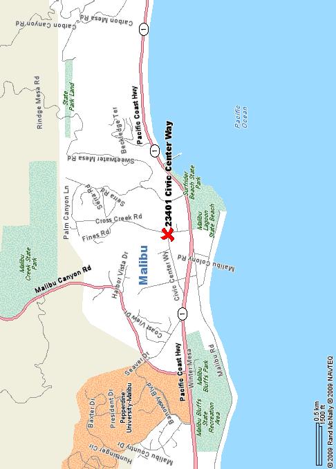
3 P.C.C.E. INC. CIVIL ENGINEERING AND DESIGN Project Introduction The proposed project site is located on Civic Center Way in the City Malibu. The surrounding area is mostly developed hillside terrain with single family residences interspersed throughout the area. All roof drainage will be outfitted with downspout filters prior to being discharged to a 1 x1 splash pad where flows will drain to proposed bioswales within the parking lots. From the bioswales, the drainage enters catch basins outfitted with an Abtech filter system. From this point the flows enter the proposed drain system shown on Sheet 2 of the grading plans prepared for this project. For further stormwater treatment, a RESI-EPIC stormwater solution is proposed which will utilize clean washed sand to further treat to site runoff. The proposed project is not required to provide onsite detention as discussions with City staff indicated that drainage studies conducted for Legacy Park revealed that the subject project was considered as a fully developed site and detention for this developed site is provided by the Legacy Park project. The purpose of the included hydrology report is to review the capacity for the proposed onsite drainage lines for planning submittal and review. The site was divided into 6 contributory areas. A summary of the hydrology and hydraulic calculations performed for the site are summarized below. Hydrologic and Hydraulic Calculations On-Site Hydrology Hydrology analysis for the subject site was performed in accordance with standards set forth in the County of Los Angeles Hydrology Manual. The drainage area was determined with the use of flown topography and was confirmed with the use of a field survey. Analysis was performed for the 50 year event. The isohyte for this area is 7.0. The soil type is 029. Below is a summary of the anticipated Q(50 YEAR) and the hydraulic calculations performed. SUBAREA DRAINAGE AREA(ACRES) Q100(PEAK FLOW RATE) AREA 1A 0.87 ACRES 3.27 CFS AREA 2A 1.12 ACRES 4.21 CFS AREA 3A 0.62 ACRES 2.33 CFS AREA 4A 1.34 ACRES 4.04 CFS AREA 5A 1.57 ACRES 4.48 CFS AREA 6A 0.21 ACRES 0.79 CFS CALABASAS ROAD, SUITE 1020, CALABASAS, CA (818) FAX (818)
4 P.C.C.E. INC. CIVIL ENGINEERING AND DESIGN On-Site Hydraulic Calculations AREA(Q100) PIPE SIZE DEPTH FULLFLOW RATE AREA 1A (3.27 cfs) 12 INCH 8.64 INCH 3.77 CFS AREA 2A (2.11 cfs) 8 INCH 6.41 INCH 2.17 CFS (2*2.11 cfs) AREA 3A (2.33 cfs) 8 INCH 6.27 INCH 2.45 CFS AREA 4A (4.04 cfs) 15 INCH 12 INCH 5.50 CFS AREA 5A (4.48 cfs) 15 INCH 8.75 INCH 6.96 CFS AREA 6A (0.79 cfs) 6 INCH 3.56 INCH 1.20 CFS TOTAL(19.1 cfs) 24 INCH-RCP INCH CFS WSPG calculations were also performed for the subject site to verify hydraulic grade lines and storm drain capacity for a 50 year storm event. The calculations are included in this report. Conclusion Hydraulic calculations performed for the proposed onsite drainage system for the project located at Civic Center Way revealed that the proposed storm drain system for this project for the various subareas is more than adequate to handle the anticipated flows during a proposed 50 year storm event CALABASAS ROAD, SUITE 1020, CALABASAS, CA (818) FAX (818)
5 EXHIBITS
6


7 -02 --DP8 A DPA DPA º 45' 00'' 03 C A L A B A S A S 1-H º 07' 30'' DPA DPA - 4 DPA DPA - 4 DPA POINT DUME 1-H DPA T O P A N G A 1-H DPA º 37' 30'' DPA º 00' 00'' 016 N W E S 7.2 DPA - 6 SOIL CLASSIFICATION AREA INCHES OF RAINFALL DEBRIS POTENTIAL AREA Miles 25-YEAR 24-HOUR ISOHYET REDUCTION FACTOR: YEAR 24-HOUR ISOHYET REDUCTION FACTOR: MALIBU BEACH 50-YEAR 24-HOUR ISOHYET 1-H1.15
8
9
10
11 HYDROLOGY
12 ï ð ð òèéð òéçì îç ðòèé ðòéçì îç é îëð òðï ðòéë îëð ðòðï ï ìòïè ðòç ðòç ̽ãøïð Âóðòëðéöøݼö ÂóðòëïçöøÔ ÂðòìèíöøÍ Âóðòïíë ë íòîé ²ñ ðòì
13 î ð ð ïòïî òéçì îç ïòïî ðòéçì îç é îîð òðï é îîð ðòðï î ìòïè ðòç ðòç ̽ãøïð Âóðòëðéöøݼö ÂóðòëïçöøÔ ÂðòìèíöøÍ Âóðòïíë ë ìòîï ²ñ ðòëï
14 í ð ð òêî òéçì îç ðòêî ðòéçì îç é îîð òðï é îîð ðòðï í ìòïè ðòç ðòç ̽ãøïð Âóðòëðéöøݼö ÂóðòëïçöøÔ ÂðòìèíöøÍ Âóðòïíë ë îòíí ²ñ ðòîè
15 ì ð ð ïòíì òéçì îç ïòíì ðòéçì îç é êðð òððë é êðð ðòððë ì íòíë ðòç ðòç ̽ãøïð Âóðòëðéöøݼö ÂóðòëïçöøÔ ÂðòìèíöøÍ Âóðòïíë è ìòðì ²ñ ðòêî
16 ëß ð ð ïòëé òéçì îç ïòëé ðòéçì îç é éðð òððë é éðð ðòððë ëß íòïé ðòèç ðòç ̽ãøïð Âóðòëðéöøݼö ÂóðòëïçöøÔ ÂðòìèíöøÍ Âóðòïíë ç ìòìè ²ñ ðòéî
17 êß ð ð ðòîï òéçì îç ðòîï ðòéçì îç é ïëð òðî é ïëð ðòðî êß ìòïè ðòç ðòç ̽ãøïð Âóðòëðéöøݼö ÂóðòëïçöøÔ ÂðòìèíöøÍ Âóðòïíë ë ðòéç ²ñ ðòï
18 HYDRAUICS
19 tmp#6.txt Manning Pipe Calculator(SUBAREA 1A) Given Input Data: Shape... Circular Solving for... Depth of Flow Diameter ft Flowrate cfs Slope ft/ft Manning's n Computed Results: Depth ft Area ft2 Wetted Area ft2 Wetted Perimeter ft Perimeter ft Velocity fps Hydraulic Radius ft Percent Full % Full flow Flowrate cfs Full flow velocity fps Critical Information Critical depth ft Critical slope ft/ft Critical velocity fps Critical area ft2 Critical perimeter ft Critical hydraulic radius ft Critical top width ft Specific energy ft Minimum energy ft Froude number Flow condition... Supercritical Page 1
20 tmp#8.txt Manning Pipe Calculator (SUBAREA 2A-2 INLETS) Given Input Data: Shape... Circular Solving for... Depth of Flow Diameter ft Flowrate cfs Slope ft/ft Manning's n Computed Results: Depth ft Area ft2 Wetted Area ft2 Wetted Perimeter ft Perimeter ft Velocity fps Hydraulic Radius ft Percent Full % Full flow Flowrate cfs Full flow velocity fps Page 1
21 tmp#9.txt Manning Pipe Calculator(SUBREA 3A) Given Input Data: Shape... Circular Solving for... Depth of Flow Diameter ft Flowrate cfs Slope ft/ft Manning's n Computed Results: Depth ft Area ft2 Wetted Area ft2 Wetted Perimeter ft Perimeter ft Velocity fps Hydraulic Radius ft Percent Full % Full flow Flowrate cfs Full flow velocity fps Page 1
22 tmp#13.txt Manning Pipe Calculator (SUBAREA 4A) Given Input Data: Shape... Circular Solving for... Depth of Flow Diameter ft Flowrate cfs Slope ft/ft Manning's n Computed Results: Depth ft Area ft2 Wetted Area ft2 Wetted Perimeter ft Perimeter ft Velocity fps Hydraulic Radius ft Percent Full % Full flow Flowrate cfs Full flow velocity fps Critical Information Critical depth ft Critical slope ft/ft Critical velocity fps Critical area ft2 Critical perimeter ft Critical hydraulic radius ft Critical top width ft Specific energy ft Minimum energy ft Froude number Flow condition... Supercritical Page 1
23 tmp#14.txt Manning Pipe Calculator (SUBAREA AREA 5A INLET) Given Input Data: Shape... Circular Solving for... Depth of Flow Diameter ft Flowrate cfs Slope ft/ft Manning's n Computed Results: Depth ft Area ft2 Wetted Area ft2 Wetted Perimeter ft Perimeter ft Velocity fps Hydraulic Radius ft Percent Full % Full flow Flowrate cfs Full flow velocity fps Critical Information Critical depth ft Critical slope ft/ft Critical velocity fps Critical area ft2 Critical perimeter ft Critical hydraulic radius ft Critical top width ft Specific energy ft Minimum energy ft Froude number Flow condition... Supercritical Page 1
24 tmp#15.txt Manning Pipe Calculator (SUBAREA 6A-INLET) Given Input Data: Shape... Circular Solving for... Depth of Flow Diameter ft Flowrate cfs Slope ft/ft Manning's n Computed Results: Depth ft Area ft2 Wetted Area ft2 Wetted Perimeter ft Perimeter ft Velocity fps Hydraulic Radius ft Percent Full % Full flow Flowrate cfs Full flow velocity fps Critical Information Critical depth ft Critical slope ft/ft Critical velocity fps Critical area ft2 Critical perimeter ft Critical hydraulic radius ft Critical top width ft Specific energy ft Minimum energy ft Froude number Flow condition... Supercritical Page 1
25 tmp#16.txt Manning Pipe Calculator(24" CONCRETE PIPE) Given Input Data: Shape... Circular Solving for... Depth of Flow Diameter ft Flowrate cfs Slope ft/ft Manning's n Computed Results: Depth ft Area ft2 Wetted Area ft2 Wetted Perimeter ft Perimeter ft Velocity fps Hydraulic Radius ft Percent Full % Full flow Flowrate cfs Full flow velocity fps Critical Information Critical depth ft Critical slope ft/ft Critical velocity fps Critical area ft2 Critical perimeter ft Critical hydraulic radius ft Critical top width ft Specific energy ft Minimum energy ft Froude number Flow condition... Supercritical Page 1
26 W.S.P.G.
27 DATE: 4/ 6/2011 TIME: 10:14 PAGE 1 WHO OUT F0515P WATER SURFACE PROFILE - CHANNEL DEFINITION LISTING CARD SECT CHN NO OF AVE PIER HEIGHT 1 BASE ZL ZR INV Y(1) Y(2) Y(3) Y(4) Y(5) Y(6) Y(7) Y(8) Y(9) Y(10) CODE NO TYPE PIERS WIDTH DIAMETER WIDTH DROP CD CD CD CD CD CD PAGE NO 3 F P WATER SURFACE PROFILE - TITLE CARD LISTING HEADING LINE NO 1 IS CIVIC CENTER WAY HEADING LINE NO 2 IS - 50 YEAR STORM EVENT HEADING LINE NO 3 IS - PAGE NO 2 PREPARED BY PCCE INC. F P WATER SURFACE PROFILE - ELEMENT CARD LISTING ELEMENT NO 1 IS A SYSTEM OUTLET * * * U/S DATA STATION INVERT SECT W S ELEV ELEMENT NO 2 IS A JUNCTION * * * * * * * U/S DATA STATION INVERT SECT LAT-1 LAT-2 N Q3 Q4 INVERT-3 INVERT-4 PHI 3 PHI ELEMENT NO 3 IS A JUNCTION * * * * * * * U/S DATA STATION INVERT SECT LAT-1 LAT-2 N Q3 Q4 INVERT-3 INVERT-4 PHI 3 PHI ELEMENT NO 4 IS A REACH * * * U/S DATA STATION INVERT SECT N RADIUS ANGLE ANG PT MAN H ELEMENT NO 5 IS A JUNCTION * * * * * * * U/S DATA STATION INVERT SECT LAT-1 LAT-2 N Q3 Q4 INVERT-3 INVERT-4 PHI 3 PHI ELEMENT NO 6 IS A REACH * * * Page 1
28 WHO OUT U/S DATA STATION INVERT SECT N RADIUS ANGLE ANG PT MAN H ELEMENT NO 7 IS A JUNCTION * * * * * * * U/S DATA STATION INVERT SECT LAT-1 LAT-2 N Q3 Q4 INVERT-3 INVERT-4 PHI 3 PHI WARNING - ADJACENT SECTIONS ARE NOT IDENTICAL - SEE SECTION NUMBERS AND CHANNEL DEFINITIONS ELEMENT NO 8 IS A REACH * * * U/S DATA STATION INVERT SECT N RADIUS ANGLE ANG PT MAN H ELEMENT NO 9 IS A JUNCTION * * * * * * * U/S DATA STATION INVERT SECT LAT-1 LAT-2 N Q3 Q4 INVERT-3 INVERT-4 PHI 3 PHI F P PAGE NO 3 WATER SURFACE PROFILE - ELEMENT CARD LISTING ELEMENT NO 10 IS A REACH * * * U/S DATA STATION INVERT SECT N RADIUS ANGLE ANG PT MAN H ELEMENT NO 11 IS A JUNCTION * * * * * * * U/S DATA STATION INVERT SECT LAT-1 LAT-2 N Q3 Q4 INVERT-3 INVERT-4 PHI 3 PHI WARNING - ADJACENT SECTIONS ARE NOT IDENTICAL - SEE SECTION NUMBERS AND CHANNEL DEFINITIONS ELEMENT NO 12 IS A REACH * * * U/S DATA STATION INVERT SECT N RADIUS ANGLE ANG PT MAN H ELEMENT NO 13 IS A REACH * * * U/S DATA STATION INVERT SECT N RADIUS ANGLE ANG PT MAN H ELEMENT NO 14 IS A REACH * * * U/S DATA STATION INVERT SECT N RADIUS ANGLE ANG PT MAN H ELEMENT NO 15 IS A SYSTEM HEADWORKS * * U/S DATA STATION INVERT SECT W S ELEV NO EDIT ERRORS ENCOUNTERED-COMPUTATION IS NOW BEGINNING ** WARNING NO. 2 ** - WATER SURFACE ELEVATION GIVEN IS LESS THAN OR EQUALS INVERT ELEVATION IN HDWKDS, W.S.ELEV = INV + DC LICENSEE: P.C.C.E. INC. F0515P PAGE 1 WATER SURFACE PROFILE LISTING CIVIC CENTER WAY 50 YEAR STORM EVENT PREPARED BY PCCE INC. Page 2
29 WHO OUT STATION INVERT DEPTH W.S. Q VEL VEL ENERGY SUPER CRITICAL HGT/ BASE/ ZL NO AVBPR ELEV OF FLOW ELEV HEAD GRD.EL. ELEV DEPTH DIA ID NO. PIER L/ELEM SO SF AVE HF NORM DEPTH ZR ********************************************************************************************************* ************************** JUNCT STR JUNCT STR JUNCT STR JUNCT STR JUNCT STR JUNCT STR LICENSEE: P.C.C.E. INC. F0515P PAGE 2 WATER SURFACE PROFILE LISTING Page 3
30 WHO OUT CIVIC CENTER WAY 50 YEAR STORM EVENT PREPARED BY PCCE INC. STATION INVERT DEPTH W.S. Q VEL VEL ENERGY SUPER CRITICAL HGT/ BASE/ ZL NO AVBPR ELEV OF FLOW ELEV HEAD GRD.EL. ELEV DEPTH DIA ID NO. PIER L/ELEM SO SF AVE HF NORM DEPTH ZR ********************************************************************************************************* ************************** Page 4
Pressure Head: Pressure head is the height of a column of water that would exert a unit pressure equal to the pressure of the water.
 Design Manual Chapter - Stormwater D - Storm Sewer Design D- Storm Sewer Sizing A. Introduction The purpose of this section is to outline the basic hydraulic principles in order to determine the storm
STREUVER FIDELCO CAPPELLI, LLC YONKERS DOWNTOWN DEVELOPMENT PHASE 1. DRAFT ENVIRONMENTAL IMPACT STATEMENT For: PALISADES POINT
 STREUVER FIDELCO CAPPELLI, LLC YONKERS DOWNTOWN DEVELOPMENT PHASE 1 DRAFT ENVIRONMENTAL IMPACT STATEMENT For: PALISADES POINT Prepared by: PAULUS, SOKOLOWSKI & SARTOR STORMWATER MANAGEMENT 1. Methodology
Hydrology Study Report
 Hafeez Consulting www.hafeezconsulting.com Civil/ Structural Engineering, Design & Construction 1451 S. Hacienda St. Anaheim CA 92804 (714) 225-4565 Fax (714)917-2977 engineer@hafeezconsulting.com Hydrology
Basic Hydraulics June 2007
 Basic Hydraulics www.concrete-pipe.org June 2007 2007 Overview Open Channel Flow Manning Equation Basic Culvert Design Sanitary Sewer Design Flow, Velocity Stormwater Sewer Design Flow, Velocity 2 Open
ARTICLE 5 (PART 2) DETENTION VOLUME EXAMPLE PROBLEMS
 DETENTION VOLUME EXAMPLE PROBLEMS") ARTICLE 5 (PART 2) DETENTION VOLUME EXAMPLE PROBLEMS Example 5.7 Simple (Detention Nomograph) Example 5.8 Offsite and Unrestricted Areas (HEC-HMS) Example 5.9 Ponds in Series w/ Tailwater (HEC-HMS) Example
ARTICLE 5 (PART 2) DETENTION VOLUME EXAMPLE PROBLEMS Example 5.7 Simple (Detention Nomograph) Example 5.8 Offsite and Unrestricted Areas (HEC-HMS) Example 5.9 Ponds in Series w/ Tailwater (HEC-HMS) Example
3301 East 120 th Avenue Assited Living & Memory Care
 UTILITY REPORT FOR 3301 East 120 th Avenue Assited Living & Memory Care 1 st Submittal January 23, 2016 2 nd Submittal March 04, 2016 Prepared for: 3301 E. 120 th Ave, LLC. 8200 E. Maplewood Ave., Suite
Eastlake Assited Living & Memory Care
 UTILITY REPORT FOR Eastlake Assited Living & Memory Care 1 st Submittal January 23, 2016 2 nd Submittal March 04, 2016 June 7, 2016 Final Submittal August 08, 2016 Prepared for: 3301 E. 120 th Ave, LLC.
City of Thornton Attn: Tim Semones Development Engineeering 9500 Civic Center Dr. Thornton, CO 80229
 Development Engineering Land Surveying Construction Administration District Services October 20, 2017 City of Thornton Attn: Tim Semones Development Engineeering 9500 Civic Center Dr. Thornton, CO 80229
Sewer Area Study. TR No (FOR OUTLET POINTS 1 & 2) January 5, 2016 JN PC11775AS SEWER AREA STUDY APPROVED /08/2016
 January 5, 2016 JN PC11775AS SEWER AREA STUDY APPROVED /08/2016") Sewer Area Study TR No 53138 (FOR OUTLET POINTS 1 & 2) January 5, 2016 JN 99610-01 PC11775AS SEWER AREA STUDY APPROVED APPROVED BY: RCE NO. DATE 70745 03/08/2016 CHECKED BY: DATE Imelda Ng 03/08/2016 COUNTY
Sewer Area Study TR No 53138 (FOR OUTLET POINTS 1 & 2) January 5, 2016 JN 99610-01 PC11775AS SEWER AREA STUDY APPROVED APPROVED BY: RCE NO. DATE 70745 03/08/2016 CHECKED BY: DATE Imelda Ng 03/08/2016 COUNTY
EROSION CONTROL NARRATIVE
 EROSION CONTROL NARRATIVE Erosion and sediment control has been designed for the Willow Bend Phase I Subdivision according to UDFCD and the City of Thornton criteria, in order to minimize erosion and sediment
Continuing Education Course #101 Drainage Design with WinTR-55
 1 of 5 Continuing Education Course #101 Drainage Design with WinTR-55 1. WinTR-55 uses the Kinematic Wave method for calculating storm runoff rates and volumes. 2. According to the Velocity Method, the
Stormwater Guidelines and Case Studies. CAHILL ASSOCIATES Environmental Consultants West Chester, PA (610)
") Stormwater Guidelines and Case Studies CAHILL ASSOCIATES Environmental Consultants West Chester, PA (610) 696-4150 www.thcahill.com Goals and Challenges for Manual State Stormwater Policy More Widespread
Stormwater Guidelines and Case Studies CAHILL ASSOCIATES Environmental Consultants West Chester, PA (610) 696-4150 www.thcahill.com Goals and Challenges for Manual State Stormwater Policy More Widespread
WATER MANAGEMENT REPORT FOR PAGE ESTATES
 WATER MANAGEMENT REPORT FOR PAGE ESTATES SLB Consulting of SW Florida, LLC PO Box 2826 Bonita Springs, FL. 34133 Phone: 239-948-9566 sandra@slbconsult.com C.O.A. # 25395 September 1, 2014 Sandra L. Bottcher
September 6, City of Thornton 9500 Civic Center Drive Thornton, CO (303) RE: Maverik Thornton, CO - Drainage Report
 RE: Maverik Thornton, CO - Drainage Report") September 6, 2016 City of Thornton 9500 Civic Center Drive Thornton, CO 80229 (303) 538-7295 RE: Maverik Thornton, CO - Drainage Report As per your request, we are submitting to you the drainage report
September 6, 2016 City of Thornton 9500 Civic Center Drive Thornton, CO 80229 (303) 538-7295 RE: Maverik Thornton, CO - Drainage Report As per your request, we are submitting to you the drainage report
Wellsgate Terrace SPECIFICATIONS.
 GRADING NOTES: 1. LOT GRADING SHALL BE COMPLETED TO PROVE SUFFICIENT DIRT ON EACH PAD TO ACHIEVE THE CRITICAL PAD GRADES AND SPOT GRADES ON EACH LOT. AFTER ACHIEVING CRITICAL PAD GRADES INDICATED ON THIS
******************* Project Description ******************* File Name... NAAF Stormwater Improvement Project 11_21_2014.SPF
 Autodesk Storm and Sanitary Analysis 2014 - Version 8.1.62 (Build 1) ----------------- *** Project Description *** File Name... NAAF Stormwater Improvement Project 11_21_2014.SPF Analysis Options Flow
DEPARTMENT OF CIVIL AND ENVIRONMENTAL ENGINEERING Urban Drainage: Hydraulics. Solutions to problem sheet 2: Flows in open channels
 DEPRTMENT OF CIVIL ND ENVIRONMENTL ENGINEERING Urban Drainage: Hydraulics Solutions to problem sheet 2: Flows in open channels 1. rectangular channel of 1 m width carries water at a rate 0.1 m 3 /s. Plot
CITY OF CAPE CORAL STORMWATER MASTER PLAN PHASE II - PART 1 BASINS 4, 10, & 14 SUB-BASIN DRAINAGE IMPROVEMENTS HYDRAULIC ANALYSIS SUMMARY
 CITY OF CAPE CORAL STORMWATER MASTER PLAN PHASE II - PART 1 BASINS 4, 10, & 14 SUB-BASIN DRAINAGE IMPROVEMENTS HYDRAULIC ANALYSIS SUMMARY Cape Coral, FL Prepared for: The City of Cape Coral Public Works
DRAINAGE REPORT FOR THORNTON SELF STORAGE THORNTON, COLORADO
 DRAINAGE REPORT FOR THORNTON SELF STORAGE THORNTON, COLORADO Prepared by: Bowman Consulting 603 Park Point Dr. Suite 100 Golden, CO 80401 (303)-801-2900 June 29, 2015 Revised August 14, 2015 CERTIFICATE
Stormwater Drainage Design Report. Reeve & Associates, Inc. Maverik, Inc. 88th Avenue and Pecos Street. Thornton, CO
 88th Avenue and Pecos Street Stormwater Drainage Design Report Reeve & Associates, Inc. Solutions You Can Build On for Maverik, Inc. 88th Avenue and Pecos Street Thornton, CO submitted to Reeve & Associates,
INFLOW DESIGN FLOOD CONTROL SYSTEM PLAN 40 C.F.R. PART PLANT YATES ASH POND 2 (AP-2) GEORGIA POWER COMPANY
 GEORGIA POWER COMPANY") INFLOW DESIGN FLOOD CONTROL SYSTEM PLAN 40 C.F.R. PART 257.82 PLANT YATES ASH POND 2 (AP-2) GEORGIA POWER COMPANY EPA s Disposal of Coal Combustion Residuals from Electric Utilities Final Rule (40 C.F.R.
INFLOW DESIGN FLOOD CONTROL SYSTEM PLAN 40 C.F.R. PART 257.82 PLANT YATES ASH POND 2 (AP-2) GEORGIA POWER COMPANY EPA s Disposal of Coal Combustion Residuals from Electric Utilities Final Rule (40 C.F.R.
Open Channel Flow I - The Manning Equation and Uniform Flow COURSE CONTENT
 Open Channel Flow I - The Manning Equation and Uniform Flow Harlan H. Bengtson, PhD, P.E. COURSE CONTENT 1. Introduction Flow of a liquid may take place either as open channel flow or pressure flow. Pressure
Section 4: Model Development and Application
 Section 4: Model Development and Application The hydrologic model for the Wissahickon Act 167 study was built using GIS layers of land use, hydrologic soil groups, terrain and orthophotography. Within
City of Columbia BMP Manual. Detailed Unified Sizing Criteria Example Wet Pond Design
 City of Columbia BMP Manual Detailed Unified Sizing Criteria Example Wet Pond Design April 17, 2013 Wet Pond Example: Unified Sizing Criteria Methodology Base Data Location: Rome, GA Site Drainage Area
LOCATED IN INDIAN RIVER COUNTY PREPARED FOR S.J.R.W.M.D. AND F.W.C.D. DECEMBER, 2003 Updated 2007 Updated May 2014 PREPARED BY
 FELLSMERE WATER CONTROL DISTRICT EAST MASTER DRAINAGE PLAN AND STORMWATER HYDROLOGIC ANALYSIS OF THE GRAVITY DRAINAGE SYSTEM LOCATED BETWEEN THE EAST BOUNDARY, LATERAL U, THE MAIN CANAL, AND DITCH 24 LOCATED
A HYDROLOGIC STUDY OF THE EFFECTS OF URBAN DEVELOPMENT ON STORM RUNOFF: A CASE STUDY IN QUEENS, NY ABSTRACT
 154 A HYDROLOGC STUDY OF THE EFFECTS OF URBAN DEVELOPMENT ON STORM RUNOFF: A CASE STUDY N QUEENS, NY Monica Tsang-Rakovan, Kevin J. Phillips, Khalid Bajwa, John Ferrelli, Fanning, Phillips and Molnar Fanning,
STORMWATER MANAGEMENT COMPUTATIONS. Mount Prospect
 STORMWATER MANAGEMENT COMPUTATIONS Mount Prospect MHG PROJECT No. 2011.173.11 November 6, 2014 Prepared for: Piney Meetinghouse Investments c/o Mr. Dennis Fling 14801 Clopper Road Boyds, MD 20841 (301)
UTILITY REPORT FOR THORNTON SELF STORAGE THORNTON, COLORADO
 UTILITY REPORT FOR THORNTON SELF STORAGE THORNTON, COLORADO Prepared by: Bowman Consulting 63 Park Point Dr. Suite 1 Golden, CO 841 (33)-81-29 June 29, 215 Revised August 14, 215 Revised September 3, 215
Chapter 5 CALIBRATION AND VERIFICATION
 Chapter 5 CALIBRATION AND VERIFICATION This chapter contains the calibration procedure and data used for the LSC existing conditions model. The goal of the calibration effort was to develop a hydraulic
PRELIMINARY CULVERT ANALYSIS REPORT FOR CULVERT NO. 008-C OREGON AVENUE OVER PINEHURST CREEK
 PRELIMINARY CULVERT ANALYSIS REPORT FOR CULVERT NO. 008-C OREGON AVENUE OVER PINEHURST CREEK Prepared for The District of Columbia Department of Transportation Washington, D.C. Prepared by Parsons Transportation
OPEN CHANNEL FLOW. One-dimensional - neglect vertical and lateral variations in velocity. In other words, Q v = (1) A. Figure 1. One-dimensional Flow
 A. Figure 1. One-dimensional Flow") OPEN CHANNEL FLOW Page 1 OPEN CHANNEL FLOW Open Channel Flow (OCF) is flow with one boundary exposed to atmospheric pressure. The flow is not pressurized and occurs because of gravity. Flow Classification
OPEN CHANNEL FLOW Page 1 OPEN CHANNEL FLOW Open Channel Flow (OCF) is flow with one boundary exposed to atmospheric pressure. The flow is not pressurized and occurs because of gravity. Flow Classification
Design Data 17. Partial Flow Conditions of Box Culverts
 Design Data 17 Partial Flow Conditions of Box Culverts Sewers, both sanitary and storm, are designed to carry a peak flow based on anticipated land development. The hydraulic capacity of sewers or culverts
STORMWATER REPORT FRITO LAY SUBDIVISION NO. 3
 STORMWATER REPORT FRITO LAY SUBDIVISION NO. 3 May 2018 STORMWATER REPORT I. Subdivision Data a. The parcel is adjacent to the existing Frito Lay property in Topeka; and the subject plat application encompasses
Sediment Capture in Pervious Concrete Pavement tsystems: Effects on Hydrological Performance and Suspended Solids
 Concrete Sustainability Conference April 14 th 2010, Tempe, AZ Sediment Capture in Pervious Concrete Pavement tsystems: Effects on Hydrological l Performance and Suspended Solids Discharge Luis A. Mata,
Submitted to: St. Johns River Power Park New Berlin Road Jacksonville, FL 32226
 RUN-ON/RUN-OFF CONTROL SYSTEM PLAN RUN-ON AND RUN-OFF CONTROL SYSTEM PLAN St. Johns River Power Park Byproduct Storage Area B Phase I Development Submitted to: St. Johns River Power Park 11201 New Berlin
TPDES: Soil, Erosion and Sedimentation Methods
 SAWS TPDES: Soil, Erosion and Sedimentation Methods Philip Handley Supervisor-Resource Protection & Compliance August 25, 2014 TPDES: Soil, Erosion and Sedimentation Methods Soil Common term: Dirt Common
BRANDON LAKES AVENUE PRE AND POST CONDITIONS DRAINAGE REPORT
 BRANDON LAKES AVENUE PRE AND POST CONDITIONS DRAINAGE REPORT Hillsborough County Public Works County Center, 22nd Floor 601 E. Kennedy Blvd. Tampa, FL 33602 BRANDON LAKES AVENUE DRAINAGE IMPROVEMENTS Capital
Chapter 10 - Sacramento Method Examples
 Chapter 10 Sacramento Method Examples Introduction Overview This chapter presents two example problems to demonstrate the use of the Sacramento method. These example problems use the SACPRE and HEC-1 computer
LECTURE 9: Open channel flow: Uniform flow, best hydraulic sections, energy principles, Froude number
 LECTURE 9: Open channel flow: Uniform flow, best hydraulic sections, energy principles, Froude number Assist. Prof. Neslihan SEMERCİ Marmara University Department of Environmental Engineering Open channel
HYDROLOGY REPORT Tentative Tract No. 5978
 ATTACHMENT 5 October 2016 HYDROLOGY REPORT Tentative Tract No. 5978 City of Simi Valley County of Ventura Prepared For: Landsea Holdings Corporation 7525 Irvine Center Drive Suite 200 Irvine, CA 92618
GIS Enabled Automated Culvert Design
 GIS Enabled Automated Culvert Design ASHTON GREER PH.D. STUDENT, THE UNIVERSITY OF ALABAMA DR. ANDREW GRAETTINGER, LEAH CLIFTON, ZACHARY WILBANKS, BRADFORD WILSON Outline Culvert Background Project Objectives
Hydrology and Hydraulics Design Report. Background Summary
 To: National Park Services Montezuma Castle National Monument Richard Goepfrich, Facility Manager From: Multicultural Technical Engineers Date: Tuesday - February 13, 2018 Subject: 30% Hydrology and Hydraulics
WQ Outlet Design Single Orifice Orifice diameter = 24. Perforated riser/orifice Plate Outlet area per perforation row = 4
 These calculations should be used when designing the outlet structures for extended wet and dry detention basins (Sections 4. 7 and 4.8). The water quality outlet size and the trash rack design will vary
D. B. G R A Y E N G I N E E R I N G I N C.
 STORMWATER MANAGEMENT REPORT 948 Hunt lub Road Ottawa, Ontario Report No. 12020-SWM August 27, 2012 Revised April 21, 2014 Revised December 9, 2014 Revised April 14, 2015 D. B. G R A Y E N G I N E E R
Preliminary Hydraulic Report
 Tarrant County, Texas Preliminary Hydraulic Report Prepared for: Texas Department of Transportation Fort Worth District Prepared by: AECOM Corporation Scott C. Williams, P.E. No. 101334, Date 2009 This
Coal Combustion Residuals Unit Inflow Design Flood Control System Plan
 Coal Combustion Residuals Unit Inflow Design Flood Control System Plan Virginia Electric and Power Company Chesterfield Power Station Upper (East) Pond Chesterfield County, Virginia GAI Project Number:
Presented by: Civil Engineering Academy
 Presented by: Civil Engineering Academy Open-Channel Flow Uniform Flow (See CERM Ch. 19) Characterized by constant depth volume, and cross section. It can be steady or unsteady Non-uniform Flow *Not on
Final Drainage Report
 Final Drainage Report Expo Rail Operations and Maintenance Facility Santa Monica, California Prepared for: Exposition Metro Line Construction Authority Prepared by: W2 Design, Inc. 50 S. De Lacey Avenue
APPENDIX B DRAINAGE REPORT
 APPENDIX B DRAINAGE REPORT B-1 South Lamar Blvd. Transportation Corridor Study Drainage Report Prepared for: City of Austin and HDR, Inc. Prepared by: and Services, Inc. Final 07-09-2015 Michael C. Meriwether,
Drainage Analysis. Appendix F
 Drainage Analysis Appendix F Golden View Drive Elizabeth Street LMORE CREEK Ricky Road Rabbit Creek Road LITTLE RABBIT CREEK East 156th Avenue MOA Project #10-026 Golden View Drive Intersection
Stormwater Capacity Analysis for Westover Branch Watershed
 Stormwater Capacity Analysis for Westover Branch Watershed Pimmit Run Little Pimmit Run, Mainstem Stohman's Run Gulf Branch Pimmit Run Tributary Little Pimmit Run, W. Branch Little Pimmit Run, E. Branch
Construction Exits Rock pads
 Construction Exits Rock pads SEDIMENT CONTROL TECHNIQUE Type 1 System Sheet Flow Sandy Soils Type 2 System Concentrated Flow [1] Clayey Soils Type 3 System Supplementary Trap Dispersive Soils [1] Minor
Advanced /Surface Hydrology Dr. Jagadish Torlapati Fall 2017 MODULE 2 - ROUTING METHODS
 Routing MODULE - ROUTING METHODS Routing is the process of find the distribution of flow rate and depth in space and time along a river or storm sewer. Routing is also called Flow routing or flood routing.
STORMWATER DESIGN CALCULATIONS
 STORMWATER DESIGN CALCULATIONS REF : C7011-2390 AT 19a-23 MEMORIAL AVENUE BLACKWALL FOR MR KERR Contents 1.0 Detention System Requirements 1.1 Storage-Area calcs. 1.2 Data Files for Pre & Post Developed
UPPER COSUMNES RIVER FLOOD MAPPING
 UPPER COSUMNES RIVER FLOOD MAPPING DRAFT BASIC DATA NARRATIVE FLOOD INSURANCE STUDY SACRAMENTO COUTY, CALIFORNIA Community No. 060262 November 2008 Prepared By: CIVIL ENGINEERING SOLUTIONS, INC. 1325 Howe
Open Channel Hydraulics I - Uniform Flow
 PDHonline Course H138 (2 PDH) Open Channel Hydraulics I - Uniform Flow Instructor: Harlan H. Bengtson, Ph.D., PE 2012 PDH Online PDH Center 5272 Meadow Estates Drive Fairfax, VA 22030-6658 Phone & Fax:
Assessment of Catch Basin Inserts
 WATERSHED PROTECTION DIVISION DEPARTMENT OF PUBLIC WORKS BUREAU OF SANITATION CITY OF LOS ANGELES Technical Report: Assessment of Catch Basin Inserts JUNE 2006 REVISED 02/21/07 WATERSHED PROTECTION DIVISION
APPENDIX B HYDROLOGY
 APPENDIX B HYDROLOGY TABLE OF CONTENTS 1.0 INTRODUCTION... 1 2.0 PROBABLE MAXIMUM PRECIPITATION (PMP)... 1 3.0 DESIGN FLOW CALCULATION... 1 4.0 DIVERSION CHANNEL SIZING... 2 5.0 REFERENCES... 4 LIST OF
SAN JACINTO RIVER / BAUTISTA CREEK LEVEE SYSTEM RIVERSIDE COUNTY, CALIFORNIA NLD ID #
 SAN JACINTO RIVER / BAUTISTA CREEK LEVEE SYSTEM RIVERSIDE COUNTY, CALIFORNIA NLD ID # 3805010019 PERIODIC INSPECTION REPORT NO 1 GENERALIZED EXECUTIVE SUMMARY FEBRUARY 2013 FINAL RATING: MINIMALLY ACCEPTABLE
Continuing Education Associated with Maintaining CPESC and CESSWI Certification
 Continuing Education Associated with Maintaining CPESC and CESSWI Certification Module 2: Stormwater Management Principles for Earth Disturbing Activities Sponsors: ODOTs Local Technical Assistance Program
Section 3.0 Existing Systems Hydrology and Hydraulics
 Section 3.0 Existing Systems Hydrology and Hydraulics This chapter summarizes the results and methodology of MACTEC s evaluation of the existing drainage systems and lakes for the City of Maitland, Florida.
WATER DISTRIBUTION NETWORKS
 WATER DISTRIBUTION NETWORKS CE 370 1 Components of Water Supply System 2 1 Water Distribution System Water distribution systems are designed to adequately satisfy the water requirements for a combinations
The effectiveness of the Natural Resource Conservation Service (NRCS) and Huff rainfall distribution methods for use in detention basin design
 and Huff rainfall distribution methods for use in detention basin design") Scholars' Mine Masters Theses Student Theses and Dissertations Spring 2010 The effectiveness of the Natural Resource Conservation Service (NRCS) and Huff rainfall distribution methods for use in detention
Scholars' Mine Masters Theses Student Theses and Dissertations Spring 2010 The effectiveness of the Natural Resource Conservation Service (NRCS) and Huff rainfall distribution methods for use in detention
Bushkill Creek 3 rd Street Dam Removal Analysis
 Bushkill Creek 3 rd Street Dam Removal Analysis HEC HMS Runoff and Routing Model Stephen Beavan, Melanie DeFazio, David Gold, Peter Mara and Dan Moran CE 421: Hydrology Fall 2010 December 15, 2010 Contents
Stone Outlet Sediment Trap
 3.12 Sediment Control Description: A stone outlet sediment trap is a small detention area formed by placing a stone embankment with an integral stone filter outlet across a drainage swale for the purpose
This site will utilize an infiltration berm to manage the two-year/24-hour volume increase.
 High Street TETRA TECH, INC. By: RH Date: 1/30/2017 Subject: High Street Checked By: JB Date: 2/1/2017 PCSM Design and Evaluation PURPOSE: The purpose of these calculations is to design a Post-Construction
Sediment Trap. A temporary runoff containment area, which promotes sedimentation prior to discharge of the runoff through a stabilized spillway.
 Sediment Trap SC-15 Source: Caltrans Construction Site Best Management Practices Manual, 2003. Description A temporary runoff containment area, which promotes sedimentation prior to discharge of the runoff
Climate Adaptation Challenges for Boston s Water and Sewer Systems
 National Association of Flood & Stormwater Management Agencies Climate Adaptation Challenges for Boston s Water and Sewer Systems John P Sullivan P.E. October 15,2014 Boston 1630 Boston 1630-2012 Boston
Materials. Use materials meeting the following.
 208.01 Section 208. SOIL EROSION AND SEDIMENTATION CONTROL 208.01 Description. Install and maintain erosion and sedimentation controls to minimize soil erosion and to control sedimentation from affecting
Stage Discharge Tabulation for Only Orifice Flow
 Stage Discharge Tabulation for Only Orifice Flow DEPTH STAGE DISCHARGE (meters) (feet) (meters) (feet) (m 3 /s) (ft 3 /s) 0 0.20 0.40 0.60 0.80 1.00 1.20 1.40 1.60 1.80 2.00 0.7 1.3 2.0 2.6 3.3 3.9 4.6
Monitoring Considerations and Costs
 Monitoring Considerations and Costs Stormwater BMP Selection, Design, and Monitoring Florida Stormwater Association September 9, 2016 Harvey H. Harper, Ph.D., P.E. Environmental Research & Design, Inc.
CITY OF PERRIS FLOOD CONTROL MAINTENANCE DISTRICT NO. 1. ANNUAL ENGINEER S REPORT FISCAL YEAR 2015/2016 May 12, 2015
 CITY OF PERRIS FLOOD CONTROL MAINTENANCE DISTRICT NO. 1 ANNUAL ENGINEER S REPORT FISCAL YEAR 2015/2016 May 12, 2015 AGENCY: City of Perris PROJECT: Flood Control Maintenance District No. 1 TO: City Council
DRAINAGE CALCULATIONS
 DRAINAGE CALCULATIONS NW 8 th Street and NW 8 th Terrace Roadway and Drainage Improvements City of Miami Project B-30745 And NW 14 th Court Roadway and Drainage Improvements City of Miami Project B-30746
EROSION CONTROL NARRATIVE
 EROSION CONTROL NARRATIVE Erosion and sediment control has been designed for the Willow Bend Phase I Subdivision according to UDFCD and the City of Thornton criteria, in order to minimize erosion and sediment
APPENDIX B DESIGN CRITERIA FOR TEMPORARY WATER QUALITY BMPS USED DURING CONSTRUCTION
 APPENDIX B DESIGN CRITERIA FOR TEMPORARY WATER QUALITY BMPS USED DURING CONSTRUCTION This Appendix presents design criteria and example calculations for the following temporary water quality BMPs for use
Appendix E Guidance for Shallow Flooding Analyses and Mapping
 Appendix E Guidance for Shallow Flooding Analyses and Mapping E.1 Introduction Different types of shallow flooding commonly occur throughout the United States. Types of flows that result in shallow flooding
PENNSYLVANIA DEPARTMENT OF TRANSPORTATION ENGINEERING DISTRICT 3-0
 PENNSYLVANIA DEPARTMENT OF TRANSPORTATION ENGINEERING DISTRICT 3-0 LYCOMING COUNTY S.R.15, SECTION C41 FINAL HYDROLOGIC AND HYDRAULIC REPORT STEAM VALLEY RUN STREAM RELOCATION DATE: June, 2006 REVISED:
Sediment Trap. At multiple locations within the project site where sediment control is needed.
 Sediment Trap SE-3 Objectives EC Erosion Control SE Sediment Control TR Tracking Control WE Wind Erosion Control Non-Stormwater NS Management Control Waste Management and WM Materials Pollution Control
Woodford County Erosion Prevention Plan and Permit. Application #
 Woodford County Erosion Prevention Plan and Permit Application # Date Instructions: Applicant will complete Parts A and B, and attach a proposed site diagram. This diagram must be completed in accordance
APPENDIX B WORKSHEETS & EXHIBITS
 APPENDIX B WORKSHEETS & EXHIBITS A worksheet provides the designer a representation of a measure that allows for input of specific design criteria. The plan designer will be required to assess field conditions
Lateral Inflow into High-Velocity Channels
 Lateral Inflow into High-Velocity Channels by Richard L. Stockstill PURPOSE: This Coastal and Hydraulics Engineering Technical Note (CHETN) investigates lateral flow discharging into a high-velocity channel.
CITY OF PERRIS FLOOD CONTROL MAINTENANCE DISTRICT NO. 1. ANNUAL ENGINEER S REPORT FISCAL YEAR 2011/2012 April 26, 2011
 CITY OF PERRIS FLOOD CONTROL MAINTENANCE DISTRICT NO. 1 ANNUAL ENGINEER S REPORT FISCAL YEAR 2011/2012 April 26, 2011 AGENCY: City of Perris PROJECT: Flood Control Maintenance District No. 1 TO: City Council
Determination of Urban Runoff Using ILLUDAS and GIS
 Texas A&M University Department of Civil Engineering Instructor: Dr. Francisco Olivera CVEN689 Applications of GIS to Civil Engineering Determination of Urban Runoff Using ILLUDAS and GIS Tae Jin Kim 03.
FHWA - HIGHWAY HYDROLOGY
 The unit peak discharge is computed with Equation 5.6 by interpolating c 0, c, and c Table 5.5 using a type II distribution. The peak discharge is also calculated as follows. from Variable SI Unit U Unit.5444
This site will utilize an infiltration berm to manage the two-year/24-hour volume increase.
 Gates TETRA TECH, INC. By: RH Date: 1/30/2017 Subject: Gates Road Checked By: JB Date: 2/1/2017 PCSM Design and Evaluation PURPOSE: The purpose of these calculations is to design a Post-Construction Stormwater
CASE STUDIES. Introduction
 Introduction The City of Winston-Salem faces the challenge of maintaining public infrastructure (e.g., water and sewer lines, storm drains, roads, culverts and bridges) while minimizing the potential impacts
5. ROADSIDE AND MEDIAN CHANNELS
 5. ROADSIDE AND MEDIAN CHANNELS Roadside and median channels are open-channel systems which collect and convey stormwater from the pavement surface, roadside, and median areas. These channels may outlet
BROADSTONE VANTAGE POINT APARTMENTS NE corner of S. Parker Road, and E. Cottonwood Drive Parker, Colorado
 BROADSTONE VANTAGE POINT APARTMENTS NE corner of S. Parker Road, and E. Cottonwood Drive Parker, Colorado PRELIMINARY DRAINAGE REPORT Strategic Land Solutions, Inc. JN: 16-002-15 Report Date/History: July
Basic Hydraulics. Rabi H. Mohtar ABE 325
 Basic Hydraulics Rabi H. Mohtar ABE 35 The river continues on its way to the sea, broken the wheel of the mill or not. Khalil Gibran The forces on moving body of fluid mass are:. Inertial due to mass (ρ
Stormwater Inlet Sediment Traps
 Stormwater Inlet Sediment Traps SEDIMENT CONTROL TECHNIQUES Photo 1 Kerb inlet Photo 2 Field (drop) inlet Table 1 provides the recommended default classification of various sediment control systems suitable
This site will utilize an infiltration berm to manage the two-year/24-hour volume increase.
 Gates TETRA TECH, INC. By: RH Date: 11/11/2016 Subject: Gates Road Checked By: JB Date: 11/13/2016 PCSM Design and Evaluation PURPOSE: The purpose of these calculations is to design a Post-Construction
ASSESSMENT OF STORM DRAIN SOURCES OF CONTAMINANTS TO SANTA MONICA BAY VOLUME I ANNUAL POLLUTANTS LOADINGS TO SANTA MONICA BAY FROM STORMWATER RUNOFF
 ASSESSMENT OF DRAIN SOURCES OF CONTAMINANTS TO SANTA MONICA BAY I ANNUAL POLLUTANTS LOADINGS TO SANTA MONICA BAY FROM WATER by Michael K. Stenstrom Department of Civil and Environmental Engineering University
3.11 Floodplains Existing Conditions
 Other stormwater control practices may be needed to mitigate water quality impacts. In addition to detention facilities, other practices such as vegetated basins/buffers, infiltration basins, and bioswales
FE Fluids Review March 23, 2012 Steve Burian (Civil & Environmental Engineering)
") Topic: Fluid Properties 1. If 6 m 3 of oil weighs 47 kn, calculate its specific weight, density, and specific gravity. 2. 10.0 L of an incompressible liquid exert a force of 20 N at the earth s surface.
Topic: Fluid Properties 1. If 6 m 3 of oil weighs 47 kn, calculate its specific weight, density, and specific gravity. 2. 10.0 L of an incompressible liquid exert a force of 20 N at the earth s surface.
Hydraulics Part: Open Channel Flow
 Hydraulics Part: Open Channel Flow Tutorial solutions -by Dr. K.N. Dulal Uniform flow 1. Show that discharge through a channel with steady flow is given by where A 1 and A 2 are the sectional areas of
SERVICING BRIEF & STORMWATER MANAGEMENT REPORT Colonial Road Sarsfield (Ottawa), Ontario. Report No June 15, 2017
, Ontario. Report No June 15, 2017") SERVICING BRIEF & STORMWATER MANAGEMENT REPORT 2980 Colonial Road Sarsfield (Ottawa), Ontario Report No. 16033 June 15, 2017 D. B. G R A Y E N G I N E E R I N G I N C. Stormwater Management - Grading &
SERVICING BRIEF & STORMWATER MANAGEMENT REPORT 2980 Colonial Road Sarsfield (Ottawa), Ontario Report No. 16033 June 15, 2017 D. B. G R A Y E N G I N E E R I N G I N C. Stormwater Management - Grading &
January 12, Mr. Ryan Granger TMGB Wilson, LLC 2221 Health Drive SW, Suite 2200 Wyoming, Michigan 49519
 January 12, 2018 Mr. Ryan Granger TMGB Wilson, LLC 2221 Health Drive SW, Suite 2200 Wyoming, Michigan 49519 Re: Proposed Reserve at Rivertown Mixed-Use Development Updated Trip Generation and Site Driveway
Lecture Note for Open Channel Hydraulics
 Chapter -one Introduction to Open Channel Hydraulics 1.1 Definitions Simply stated, Open channel flow is a flow of liquid in a conduit with free space. Open channel flow is particularly applied to understand
REPORT FOR: ISLAND LAKE ESTATES 4275 Placida Road Englewood, FL 34224
 REPORT FOR: ISLAND LAKE ESTATES 4275 Placida Road Englewood, FL 34224 OWNER/APPLICANT: Edgewater Opportunity Fund II Contact: Ronald S Greenland 300 East Bay Heights Road Englewood, FL 34223 SUBMITTED
Sediment Control Practices. John Mathews Ohio Dept. of Natural Resources, Division of Soil and Water Resources
 Sediment Control Practices John Mathews Ohio Dept. of Natural Resources, Division of Soil and Water Resources Practices Treat the Largest Soil Particles Sand Sand Silt Clay Treated Untreated Settleable