United States Army Corps of Engineers Engineering Manual EM
|
|
|
- Griffin Carr
- 6 years ago
- Views:
Transcription
1 United States Army Corps of Engineers Engineering Manual EM
2 Chapter 2 Open Channel Hydraulic Theory 2
3 Open Channel Hydraulic Theory Physical Hydraulic Elements Hydraulic Design Aspects Flow Through Bridges Transitions Flow in Curved Channels Special Considerations Stable Channels 3
4 Physical Hydraulic Elements Channel slope Cross-sectional area Wetted perimeter Most efficient section Boundary surface roughness 4
5 Invert Slope Controlled by surrounding topgraphy Can be altered to achieve desired project goals, but Cut/fill can be expensive Effect on hydraulics and costs Need to examine out of reach influences 5
6 Channel Cross-Section Balance capacity with costs Typically: Trapezoidal for rural areas Rectangular for urban reaches V-bottom for minimizing effects of sediment 6
7 Roughness Absolute roughness Theoretical interest only Effective roughness Dimension of length Effective roughness height Composite roughness Most common approach 7
8 Open Channel Hydraulic Theory Physical Hydraulic Elements Hydraulic Design Aspects Flow Through Bridges Transitions Flow in Curved Channels Special Considerations Stable Channels 8
9 Hydraulic Design Elements Assumptions Friction Losses Friction Coefficients Flow Classification 9
10 Assumptions Familiar with concepts of: Uniform flow Gradually varied flow Conservation of Energy Conservation of Momentum Conversion of friction loss terms Have or have access to Chow (1959) 10
11 Hydraulic Design Elements Assumptions Friction Losses Friction Coefficients Flow Classification 11
12 Friction Losses Three main equations/concepts Chezy Manning Darcy-Weisbach Included Losses due to friction Uniform turbulence and eddy losses Not Included Local turbulence and eddy losses 12
13 Types of Fluid Flow Laminar Flow flow persists as unidirectional movement Molecules flow parallel Movement up and down by diffusion Turbulent Flow highly distorted flow Large scale flow perpendicular to direction of flow Transfer of movement up and down by macroscale processes Turbulence = irregular and random component of fluid motion Eddies = highly turbulent water masses 13
14 14
15 Laminar vs Turbulent Flow Laminar flow velocity constant at a point over time Turbulence Most flows = turbulent Slow settling velocity upward motion of water particles Increases effectiveness of fluid in eroding and entraining particles from the bed; but less efficient transport agent Velocity measured at a point over time tends towards an average value; but varies from instant to instant 15
16 Friction Losses Type of Energy Losses In consideration of the energy losses in fluid flow, they are generally broken down into 2 types: Major losses Minor losses 16
17 Friction Losses Major Head Losses Major head losses are a form of energy considered to take place continuously along the path of flow. These losses are generally called Friction Head Losses. 17
18 Friction Losses Minor Head Losses Minor head losses are those losses generally created by increased turbulence and resistance to flow at points in the stream where the direction of flow is changed or where other obstruction tale place. The most commonly encountered forms of minor head losses are as follows: Hf head losses due to a sudden of gradual enlargement of the cross section of flow. Hc head losses due to a sudden of gradual contraction of the cross section of flow. Hg head losses due to obstruction in the path of flow (gates, valves, metering devices, and so on) Hb head losses occurring at bends and changes in direction of the flow path. 18
19 Friction Losses Total Head Losses The total head loss in a stream of flowing fluid is equal to the sum of all the head losses along its path Total Head Losses = Major Head Losses + Minor Head Losses H = h + h + h + h + h l f e c g b 19
20 Hydraulic Design Elements Assumptions Friction Losses Friction Coefficients Flow Classification 20
21 Recap If depth & velocity remain constant over a length of channel which has a constant cross-section and slope, then the flow is uniform and water surface will be parallel to streambed. The depth is called the normal depth. If depth and/or velocity change over distance then it is varied flow, which can be divided into gradually varied or rapidly varied 21
22 Steady Flow Law of continuity Q = V 1 A 1 = V 2 A 2 = Q = discharge, V = Average velocity, A = cross sectional area Must have continuous, steady-varied flow Flow may also be: Unsteady-varied Unsteady-uniform Steady-uniform 22
23 Uniform flow Gravity (force causing motion) Friction (force opposing motion) For uniform flow the gravity force will equal the friction force and the energy line, the water surface and the streambed will be parallel (have the same slope) 23

24 Analysis of Major Energy Losses Antoine Chezy, in 1775 Chezy Analysis and Formula A French civil engineer developed the Chézy equation, which relates the uniform flow velocity to channel roughness, hydraulic radius, and bed slope. v = C Rs v = average velocity of flow R = hydraulic radius S = slope of the channel C = coefficient depending upon the various characteristics of the channel and their comparison with those of another similar channel 24
25 Chezy s Equation The gravitation force is approximately proportional to the velocity squared V= (ρg/α)rs V is the mean velocity (ft/s) α is a coefficient mainly dependent on channel roughness 25
26 Chezy s C The term (ρg/α) was later replaced with a single coefficient C C has units of (ft 1/2 /s) And varies from: 30 (small rough channels) 90 (large smooth ones) 26
27 27
28 Chezy Where: S f = EGL slope V = velocity C = Chezy coefficient R = Hydraulic radius 28
29 Chezy Hydraulically smooth channels Where: C = Chezy coefficient R n = Reynolds number 29

30 Reynolds Number Re VL = or υ Internal Forces Viscous Forces Where: R e = Reynolds number L = characteristic length ν = kinematic viscosity V = velocity 30
31 Chezy Hydraulically rough channels Where: C = Chezy coefficient k = effective roughness R = hydraulic radius 31
32 Hydraulically Rough or Smooth? Hydraulically rough k s > k c Hydraulically smooth K s < k c 32
33 Hydraulically Rough or Smooth? Where: k c = Equivalent roughness C = Chezy C ν = kinematic viscosity g = gravity V = Velocity 33

34 Darcy-Weibach Formula Henry Darcy, 1857 Showed that f is not dimensionless but dependent upon numerous parameters -the roughness of conduit wall -the velocity of flow -the viscosity and density of fluid -the diameter of pipe 34

35 Darcy-Weibach Formula Julius Weisbach, Developed a formula for pipe flow, based to some extent on the Chezy formula. l v 2 h = fx x f = friction factor f d 2 g d = pipe diameter l = pipe length h f = head losses over pipe length v = velocity 35

36 Analysis of Major Energy Losses Darcy-Weibach Formula Values for f for water flowing in straight smooth pipe are shown in table. 36
37 Darcy Weisbach f Where: S f = EGL slope V = velocity f = Darcy-Weisbach coefficient R = Hydraulic radius 37
38 Reynolds Number Moody Diagram L.F. Moody developed the diagram which expresses the relationships between -Reynolds number -f for various ranges of values of k/d Moody diagram -all curves are concave upward and tend to flatten out as value of R e increase. R e = 400 d k log(3.7 d k ) 38

39 Moody Diagram Friction Factor Reynolds Number 39

40 Open-Channel Flow Formulas Manning Formula Robert Manning, in 1885 Developed Manning formula used for open channel flow conditions. v = 1 2 / 3 1/ 2 R s n v = velocity of flow, m/s R = hydraulic radius, m S = slope of the energy gradient n = a roughness coefficient 40
41 Manning s Equation V= 1/n R 2/3 S 1/2 Q= 1/n AR 2/3 S 1/2 Q is discharge (ft3/s) n is a coefficient known as Manning s n SI units (imperial are multiplied by 1.486) n = sd 1/6 d is the median diameter in (mm) d 50 for which 50% of streambed particles are smaller n = (0.1129R 1/6 )/(1.16+2log(R/d 84 )) d 84 is the diameter (m) for which 84% of streambed particles are smaller 41
42 Manning Where: V = velocity S f = EGL slope n = Manning s n R = Hydraulic radius 42
43 Manning s n Examples 43
44 Manning s n Examples 44
45 Coefficient Relation 45
46 Plate 3 k to C and f Plate 3 46
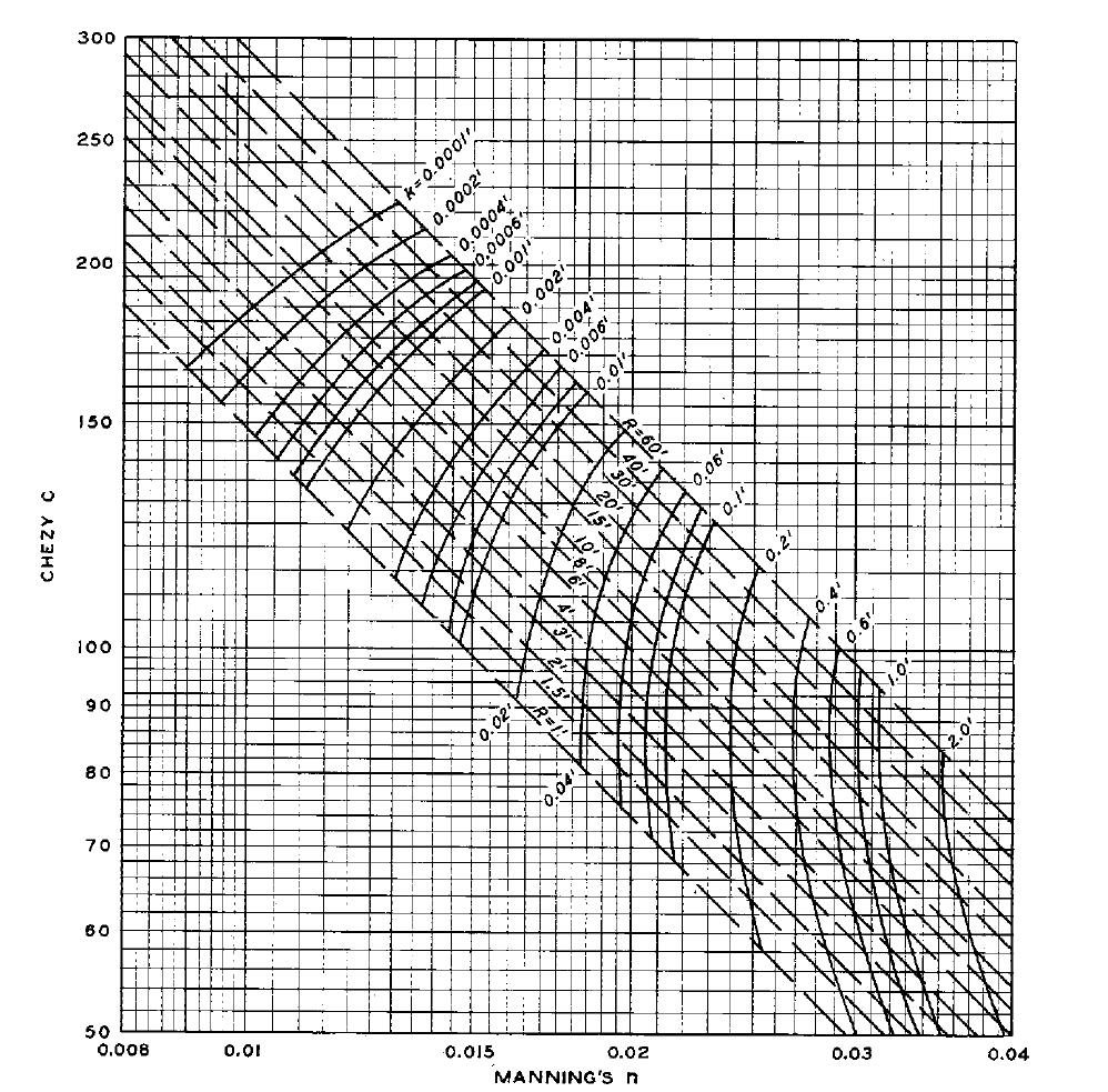
47 Hydraulically Rough Channels Plate 5 47


48 Hydraulically Rough Channels Plate 4 Stop 15 SEP 08 48
49 Rules of Thumb Most channels are hydraulically rough k values for natural rivers: 0.1 to 3.0 (ft) Typically larger than spherical diameters of bed materials why?? 49
50 Rules of Thumb If field data is available Determine k from: EQ
51 Rules of Thumb If field data is available Determine k from Equation 2-6 Value of k can be assumed for flow levels at or lower than observed condition Appendix C outlines method for determining an effective roughness 51
52 Why use k? Can be assumed to be spherical diameter of average bed material What if losses other than friction? Consider relations: k does not vary with R n varies with R 1/6 52
53 However k must be evaluated for each subsection Use subsections: Differing bed materials Bed forms present Expansions and contractions Form roughness significant 53
54 Why do we need to know all this stuff? Environmental flows Depth of flow Min particle size to prevent erosion The depth of flow is obviously important in calculating possible flood depths. But its not that simple, we actually use this for back water calculations. 54
55 Hydraulic Design Elements Assumptions Friction Losses Friction Coefficients Flow Classification 55
56 Flow Classification Tranquil and rapid flow Pulsating rapid flow Varied Flow 56
57 Tranquil vs. Rapid Flow Distinction centered around specific energy and critical depth 57
58 Depth vs. Specific Energy 58
59 Depth vs. Specific Energy Tranquil Flow d > 1.1dc or Fr < 0.86 Rapid Flow d < 0.9dc or Fr >
60 Depth vs. Specific Energy If in instability region: Evaluate both high and low resistance values Adjust slope (or k) to design in proper zone 60
61 Pulsating Rapid Flow Occurs at Froude numbers much greater than 1 Formation of slugs Typically on steep slopes with shallow depths What is effect? 61
62 Pulsating Rapid Flow Need to determine roughness Concept of limiting Froude number Rather difficult to quantify 62
63 Roughness Where: R = Hydraulic radius n = Manning s n F = Froude number of flow Fs = Limiting Froude number EQ
64 Limiting Froude Number EQ Where: Fs = Limiting Froude number g = Gravity ξ = Flow function ζ = depth/width ratio Z = Channel side slope 64
65 Limiting Froude Number Where: ξ = flow function ζ = depth/width ratio d = flow depth b = bottom width 65
66 Pulsating Rapid Flow Q = 1000 b = 10 Y = 3 z = 2 Fs = 2.12?? z = 0 Fs = 3.4?? Plate 7 66
67 Varied Flow Profiles Prismatic Channels Unvarying cross sections Constant invert slope Straight alignment How to determine profile Direct integration Direct step Standard step Start 11 SEP 67
68 Direct Step Method x = E 2 E So Sf 1 Calculation steps Determine starting depth Assume second depth and compute parameters associated with that depth Solve for step length 68
69 Direct Step Method Compute Upstream direction Subcritical flow Downstream direction Supercritical flow Utilize small changes of y so that: S f = 2 2 nv 2.22R 4/3 S f = fv 2 8gR 69
70 Standard Step Method Calculation steps Assume WS 2 at upstream location Compute associated velocity head Solve for Sf Solve for WS 2 Compare with assumed WS 2 Iterate as needed 70
71 Comparison No Comparison between direct step and standard step methods. Characteristic Ease of computation Type of cross section Independent variable Dependent variable Calculation advances -> Accuracy increases with -> Type of cross-section input Data needs Tools Reliability Direct step method Easy (hours) prismatic flow depth length of channel directly a smaller flow depth increment one typical cross section (prismatic) minimal spread sheet (or programming) Answer always possible Standard step method Difficult (months) any (prismatic or nonprismatic) length of channel flow depth by iteration (trial and error) lesser cross-sectional variability many cross sections (nonprismatic) extensive HEC-RAS (or programing) Answer sometimes not possible (depends on the type of crosssectional data) 71
72 Open Channel Hydraulic Theory Physical Hydraulic Elements Hydraulic Design Aspects Flow Through Bridges Transitions Flow in Curved Channels Special Considerations Stable Channels 72
73 Flow Through Bridges Energy losses Turbulence Water surface elevations 73
74 Abutment Losses Rapid flow Stay out of channel! Tranquil flow Flow depth between abutments is > yc Preliminary layout 1.0 for expansion loss 0.5 for contraction loss Bradley (1978) Design charts 74
75 Pier Losses Three conditions (Chow 1959) Class A Class B Class C 75
76 Three condition s Energy Class A Momentum Class B Class C Pier Losses Momentum Plate 10 76

77 Pier Losses Plate 11 77
78 Energy Method E1 = E2 + hl 1 2 E2 = E3 = hl 2 3 Where: E1 = Energy at Section 1 E2 = Energy at Section 2 E3 = Energy at Section 3 hl 1-2 = Losses between sections 1 and 2 hl 2-3 = losses between sections 2 and 3 78
79 Momentum Method Where: M = momentum per unit time (lbs) β = momentum correction factor (1.0) Q = discharge (cfs) V = average channel velocity (fps) 79
80 Momentum Method Where: m 1 = hydrostatic force in section 1 m p = hydrostatic force on pier ends m 2 = hydrostatic force in section 2 m 3 = hydrostatic force in section 3 80
81 Pier Losses Plate 12 81

82 Analysis Tools Plate 14 Plate 15 82


83 Analysis Tools Plate 16 Plate 17 83
84 Open Channel Hydraulic Theory Physical Hydraulic Elements Hydraulic Design Aspects Flow Through Bridges Transitions Flow in Curved Channels Special Considerations Stable Channels Start 22 SEP 84

85 What Is A Transition? Structure that joins two geometrically dissimilar cross-sections Contraction or expansion of flow Minimizes flow disturbance Affects the water surface elevation through energy loss 85
86 Transitions Contraction & Expansion Plan View width 1 b 1 b 2 width 2 Contraction b 1 > b Expansion b 1 < b 2 86


87 Application of Transition Structures Approach to bridge and culvert crossings A placeholder between existing and future improvements To create a choke in the channel 87
88 Analysis of Transition Structures 88
89 Principles of Open Channel Hydraulics Three Governing Principles Conservation of Mass Conservation of Momentum Conservation of Energy E = E Losses 89
90 Energy Equation (Bernoulli s) elevation head y + z + 1 = 2 + y + z h L, 1 2 v p v p 2g γ 2g γ velocity head pressure head Energy loss between sections 1 and 2 90
91 Open Channel Energy Equation Q Channel Bottom z 1 z 2 Datum v 1 2 g v 2 g y 1 + z 1 = + y 2 + z 2 + h L,1 2 91
92 Open Channel Energy Equation HGL y 1 Channel Bottom y 2 z 1 z Datum v 1 2 g v 2 g y 1 + z 1 = + y 2 + z 2 + h L,1 2 92
93 Open Channel Energy Equation v g HGL 2 v 1 2 g y 1 + z 1 = + y 2 + z 2 + h L EGL v 2 g,1 2 y 1 v g Channel Bottom y 2 z 1 z Datum
94 Open Channel Energy Equation 2 v 1 2 g v 2 g y 1 + z 1 = + y 2 + z 2 + h L,1 2 v g HGL EGL h L1-2 y 1 v g Channel Bottom y 2 z 1 z Datum
95 Open Channel Energy Equation Head Losses h = Major Losses + Minor Losses L1 2 Friction between fluid and it s flow boundary Change in velocity or change in flow 95
96 Open Channel Energy Equation Losses due to Transitions are considered Minor Losses h = Major Losses + Minor Losses L1 2 Change in velocity or change in flow 96
97 Open Channel Energy Equation General Equation for Minor Losses h L m = K m V 2g 2 97
98 Transition Types For connecting trapezoidal and rectangular sections Cylindrical quadrant Warped Wedge Rectangular sections Straight-line Abrupt/square 98
99 Types of Transitions Warped Straight Line Cylindrical Quadrant Wedge (longer or shorter than warped?) Abrupt (square) 99

100 Abrupt Transition 100
101 Channel Transitions Subcritical Flow Each type can be used in either direction Cylindrical quadrant used for: Expansions from rectangular to trapezoidal Contractions from trapezoidal to rectangular Straight-line transition or quadrant for rectangular channels 101
102 Channel Transitions Supercritical Flow Cylindrical quadrant Subcritical in trap section to supercritical in rectangular Straight-line for contractions in rectangular sections Special shape for expansions in rectangular channel 102
103 Transition Design Subcritical Flow Rectangular to trapezoidal Wedge Type Plate
104 Plate
105 Transition Design Subcritical Flow Rectangular to trapezoidal Plate 20 6 o maximum change in flow line Water surface profiles determined by step computations < 20 percent change in velocity between steps Adjust to make water surface as straight as practicable 105
106 Transition Design Supercritical Flow Between trapezoidal and rectangular Typically incorporate wedge or straight-line transition Need to minimize/contain standing waves Rule of thumb: 106
107 Recommended Convergence and Divergence Rates Mean channel velocity (fps) 1-10 Wall flare (horizontal to longitudinal) 1: : :20 107
108 Transition Design Supercritical Flow Rectangular contractions: 108
109 Plate
110 Transition Design Supercritical Flow Rectangular contractions: EQ 2-22 EQ 2-23 EQ
111 Transition Design Supercritical Flow Rectangular contractions: EQ 2-25 However, disturbances are minimized when L = L 1 + L 2 so.. EQ 2-26 EQ
112 Transition Design Supercritical Flow Rectangular contractions: Correct design requires choosing a value of Θ so that L = L 1 + L 2 Either solve equations simultaneously or use Plate 22 Plate 23 is a go-by 112

113 Plate 22 Plate
114 EQ Plate
115 Transition Design Supercritical Flow Rectangular expansions Model studies have shown that changes in flow direction are much more gradual in expansions than in contractions Theory and empirical data show that a curved transition helps regulate wave propagation Model testing has indicated that downstream depths can be significantly greater than what theory predicts 115
116 Transition Design Supercritical Flow Rectangular expansions 116
117 Transition Design Supercritical Flow Rectangular expansions EQ 2-25 Where: Z = Transverse distance from channel centerline b 1 = approach channel width X = longitudinal distance from beginning of expansion F 1 = approach Froude number 117
118 Plate
119 Transition Design Supercritical Flow Non-rectangular transitions: No real design guidance, typically need to model 119
120 Transition Design Supercritical to Subcritical Flow Typically expansions from rectangular to trapezoidal Wedge type transition Can be rapid or gradual Jump needs to be contained within transition Scenario?? 120
121 121
122 122

123 123
124 Transition Losses Subcritical flow Design should minimize energy losses and costs Supercritical Flow Can be substantial and drive the design 124
125 Transition Loss Equations Contraction: h = K c V V 2g Expansion: h = K e V 2 1 V 2g
126 Transition Loss Coefficients SHAPE Abrupt (Square) Straight Line Warped Design K c (Contraction) K e (Expansion)
127 Design Considerations Define purpose of structure Define project constraints Right-of-Way Site conditions Economic feasibility Location of transition structure Design will be case by case 127
128 General Guidelines for Design 1. Define design parameters Design discharge, Q (cfs) Geometry of existing and proposed channel section 2. Determine location of transition structure 3. Length of transition structure 4. Determine transition head loss, H t 5. Determine existing WSE at beginning and end of preliminary location of transition 6. Based on initial water surface elevation calculation (output), refine design of transition 128
129 Key Points to Remember Transitions in Subcritical Flow are analyzed using the Energy Equation Transition losses are energy losses associated with a change in velocity If possible, avoid design of transitions in supercritical and unstable range of flows Design of transitions is case by case and comes with experience 129
130 References 1. Chow, V. T., Open Channel Hydraulics, McGraw Hill Book Co., Inc. New York (1959) 2. Ippen, A. T., Mechanics of Supercritical Flow, Transactions, ASCE, Vol. 116 (1951) 3. Ippen, A. T. and Dawson, J. H., Design of Channel Contractions, Transactions, ASCE, Vol. 116 (1951) 4. Rouse, H., Bhoota, B. V., and Hsu, En-Yun, Design of Channel Expansions, Transactions, ASCE Vol. 116 (1951) 5. Knapp, R. T., Design of Channel Curves for Supercritical Flow, Transactions, ASCE, Vol. 116 (1951) 6. Morris, Henry M. and Wiggert, James M., Applied Hydraulics in Engineering, Second Edition, John Wiley & Sons 7. U. S. Army, Office, Chief of Engineer, Hydraulic Design of Flood Control Channels, Engineer Manual EM (1970) 8. Mostafa, M. Gamal, Open Channel Transitions in Subcritical Flow, Final Report No. ERC FR, (1978) 9. Orange County Flood Control District Design Manual, O.C.F.C. D., Orange County, California 10. Majaj, Nadeem H., Appendix A Basics of Hydraulics, Basin Analysis Software User s Manual, Hydraulic Solutions, Inc. (2003) Note: Graphics and text depicting the Energy Equation were obtained from another slide presentation on the web. Author was not named. 130
131 Open Channel Hydraulic Theory Physical Hydraulic Elements Hydraulic Design Aspects Flow Through Bridges Transitions Flow in Curved Channels Special Considerations Stable Channels Start 6 OCT
132 Flow in Curved Channels Superelevation Limiting curvature Bend losses Shear stress 132
133 Flow in Curved Channels Superelevation Secondary currents Shift in maximum velocity 133
134 Flow in Curved Channels Superelevation VW 2 y = C gr EQ Where: y = rise in water surface C = coefficient V = average velocity W = channel width g = gravity r = radius of curvature 134
135 Flow in Curved Channels Superelevation Subcritical Increase wall height along outside of curve to account for rise in water surface elevation Can have waves on inside of channel bend 135
136 Flow in Curved Channels Superelevation Supercritical Effect propagated downstream requiring increased wall height Mitigation Spiral transition curves Spiral banked curves Limiting curvature 136
137 Flow in Curved Channels Spiral transition curves Induce curvature and superelevation at a gradual rate Gradually increases from infinity to a maximum value at plan view center point VW L s = 1.82 gy EQ
138 Flow in Curved Channels Spiral banked curves Used in rectangular channels Rotate channel bottom about centerline Maximum banking twice y from EQ 2-31 Inside bend depressed by y Outside bend elevated by y Permits wall heights to be equal on both sides of channel 138
139 Flow in Curved Channels Limiting curvature Subcritical flow Rc >3 times channel width Supercritical flow Use Equation
140 Flow in Curved Channels r min 2 4V W EQ gy Where: r min = minimum radius of curvature V = average velocity W = channel width at design water surface y = flow depth 140
141 Flow in Curved Channels Bend losses Scobey (1933) recommended increasing n by for each 20 o of curvature per 100 feet of channel Maximum increase of Minor losses in HEC-RAS, assumed to be negligent Effective roughness due to secondary currents Recent experiments indicate that losses can be significant for values of r c /W < ~4 141
142 Curved Channels and Shear Stress 142
143 Shear Stress Distribution Upstream Bend Baseline Test 16cfs 12cfs psf psf 8cfs psf Flow Direction psf psf psf psf psf 143
144 Design Guidance: EM-1601 (1970) 144
145 Design Guidance: HEC-15 (1988) R c = Centerline Radius of Curvature B = Channel bottom width K b = τ b / τ o τ b = Maximum bend shear stress τ o = Average approach shear stress 145
146 Data Information Ippen,, A. T., et. al. (1962) ; 16 data points USBR (1964) ; 1 data point Yen, B.C. (1965) ; 5 data points CSU / USBR (2002) ; 8 data points Characteristics (for all sets) Trapezoidal channels Preston Tube utilized for shear measurements Rigid boundary
147 Bend Geometry Ranges Variable Range Side Slope 1 to 2 Bottom Width 1 to 10.2 ft Top Width 1.67 to ft Centerline Radius of Curvature 5 to 65 ft Centerline Radius of Curvature / Top Width 1.22 to 6.73 Centerline Radius of Curvature / Bottom Width 2.5 to 10.83
148 HEC-15 Method Maximum Shear in Channel Bends Ippen (1962) USBR (1964) Yen (1965) CSU (2002) Ippen (1962) Ippen Ippen USBR (1962) (1962) (1964) USBR USBR (1964) Yen (1964) (1965) Yen Yen (1965) (1965) CSU CSU (2002) CSU (2002) (2002) Original HEC-15 Curve Upper Envelope Original HEC-15 Curve Upper Envelope Curve Kb Kb = = τb τb / / τo τo Upper Envelope Curve K b = 4.89(r c /b) Original HEC-15 Curve Original HEC-15 Curve K K b = 2.86(r c /b) b = 2.86(r c /b) Best Fit on All Data K b = 3.16(r c /b) R 2 = Centerline Radius of Curvature, r c / Bottom Width, b
149 EM-1601 Method Maximum Shear in Channel Bends Ippen (1962) USBR Ippen (1964) (1962) USBR Yen (1964) (1965) Yen (1965) CSU (2002) CSU (2002) Original EM-1601 Equation Kb = τb / τo Upper Envelope Equation K b = 3.53(r c /w) Best Fit on All Data Best Fit on All Data K K b = 2.63(r b = 2.63(r c /w) c /w) R 2 R 2 = 0.80 = 0.80 Original EM-1601 Equation K b = 2.65(r c /w) Centerline Radius of Curvature, r c / Top Width, w
150 Comparison of Methods Shear Stress Correction Factor for Channel Bends Linear Fit Fit to to Data Data Line Line of of Equal Fit Fit Kb = τb / τo (CSU/USBR Best Fit Equation) Kb = τb / τo (CSU/USBR Upper Envelope Equation) y = 1.44x y = 1.09x 65 % Maximum Variability K b = K b τ b = / τ b o / τ o (HEC-15) Envelope) 22 % MaximumV ariability
151 Reality 151

152 3-D problem 152
153 Application Boundary shear stress has been determined to be a fundamental part of channel migration (Brown, 1988) 153
154 Theory - Overview Boundary Shear Stress in a stream bend can be expressed as τ =τ +τ b viscous turbulent τ viscous = viscous boundary shear stress in a stream bend τ turbulent = turbulent boundary shear stress in a stream bend Start 8 OCT 08
155 And in further detail as τ o τ lat τ b = total boundary shear stress in a stream bend = average longitudinal viscous shear stress lat = average lateral viscous shear stress = average additional viscous shear stress due to channel geometry τ g Theory - Overview Viscous Turbulent τ =τ +τ +τ +τ +τ +τ b o lat g zx yx zy τ zx = average vertical turbulent shear stress component in longitudinal inal direction τ yx = average lateral turbulent shear stress component in longitudinal nal direction τ zy = average vertical turbulent shear stress component in lateral direction
156 Theory - Illustration Viscous Flow Direction Top of Bank Turbulent τ =τ +τ +τ +τ +τ +τ b o lat g zx yx zy Cross Section Centerline τ zy τ lat θ τ o τ g τ zx τ yx τ b Toe of Bank 156
157 Theory - Illustration Flow Direction Top of Bank Cross Section Centerline τ zy τ lat θ τ o τ g τ zx τ yx τ b Toe of Bank 157
158 Theory Viscous Shear Stress τ =γrs o f Where: τ o = average longitudinal viscous shear stress γ = unit weight of water R = hydraulic radius S f = friction slope
159 Theory Viscous Shear Stress V 2 z x lat z y y ρ τ =ρv V +γs z r Where: τ lat = average lateral viscous shear stress γ = unit weight of water r = centerline radius of curvature ρ = density of water S y = lateral water surface slope V x = average velocity in the x-direction V y = average velocity in the y-direction
160 Theory Viscous Shear Stress τ =τ τ g s o Where: τ g = average additional viscous shear stress due to channel geometry τ o = average longitudinal viscous shear stress τ s = average longitudinal boundary shear stress due to super elevation
161 Theory - Illustration Flow Direction Top of Bank Cross Section Centerline τ zy τ lat θ τ o τ g τ zx τ yx τ b Toe of Bank 161
162 Theory - Illustration τ zx + τ zx z τ yx y δz τ xx τ xx + τ xx τ yx + τ yx δy δx τ zx x 162
163 Theory Turbulent Shear Stresses ( ) 2 u' ( u'v' ) ( u'w' ) τ ρ ρ ρ xx τ xy τxz τ τ τ = ρ ρ ρ = ( ) ( ) 2 ( ) yx yy yz v'u' v' v'w' τ 2 zx τ zy τzz app ρ w'u' ρ w'v' ρ w' normal to the x-plane applied in the x-direction normal to the y-plane applied in the x-direction normal to the z-plane applied in the x-direction ( ) ( ) ( ) normal to the x-plane applied in the y-direction normal to the y-plance applied in the y-direction normal to the z-plane applied in the y-direction normal to the x-plane applied in the z-direction normal to the y-plane applied in the z-direction normal to the z-plane applied in the z-direction
164 Theory Turbulent Shear Stresses ( ) 2 u' τ ρ xx ( ) ( ) 2 τyx τ yy = ρ v'u' ρ v' = τ 2 zx τ zy τzz app ρ w'u' ρ w'v' ρ w' normal to the x-plane applied in the x-direction normal to the y-plane applied in the x-direction normal to the z-plane applied in the x-direction ( ) ( ) ( ) normal to the y-plance applied in the y-direction normal to the z-plane applied in the y-direction normal to the z-plane applied in the z-direction
165 Theory Turbulent Shear Stresses τ ( ) yx = ρ v'u' = τ ( ) ( ) zx τ zy ρ w'u' ρ w'v' normal to the y-plane applied in the x-direction normal to the z-plane applied in the x-direction app normal to the z-plane applied in the y-direction
166 Theory - Illustration Flow Direction Top of Bank Cross Section Centerline τ zy τ lat θ τ o τ g τ zx τ yx τ b Toe of Bank 166
167 Illustration 167
168 Illustration 168
169 τ o Example Data Model discharge was 20 cfs. was calculated to be psf Cross Section Piezometer C C C C C C C C τ p (lb/ft 2 ) τ g (lb/ft 2 ) % of τ o 0% 28% 68% 23% 14% 5% 23% 49% τ lat (lb/ft 2 )* % of τ o 0% 13% 31% 13% 10% 4% 9% 22% * These values were estimated. XS # Piezo % Depth τ yx % of τ o τ zx % of τ o τ zy % of τ o (psf) (psf) (psf) 1 C % % % 2 C % % % 3 C % % % 4 C % % % 5 C % % % 6 C % % % 7 C % % % 8 C % % % 169
170 Illustration of Example Piezo C Cross Section 5 In this particular example, τ b, would have a magnitude of τ zy τ lat θ τ o τ g τ zx τ yx psf with an angle θ of 82.4 degrees, which is a τ b total of 68% larger than τ o. 170
171 Summary of Theory Total boundary shear stress in a stream bend can be theoretically calculated, however: All terms except, τ o, require a detailed set of data The dataset would require: Direct shear measurements Water surface elevations throughout and across the bend Turbulent three-dimensional velocities Detailed channel geometry All of which are not generally available 171
172 Shear Stress Distribution Upstream Bend Baseline Test 16cfs 12cfs psf psf 8cfs psf Flow Direction psf psf psf psf psf 172
173 HEC-15 Method Maximum Shear in Channel Bends Ippen (1962) USBR (1964) Yen (1965) CSU (2002) Upper Envelope Original HEC-15 Curve Upper Envelope Curve Upper Envelope Curve K b = 4.89(r c /b) Kb = τb / τo Original HEC-15 Curve K b = 2.86(r c /b) Best Fit on All Data K b = 3.16(r c /b) R 2 = Centerline Radius of Curvature, r c / Bottom Width, b
174 HEC-15 Method 3.5 Maximum Shear in Channel Bends (HEC-15) Ippen (1962) USBR (1964) Yen (1965) Upper Envelope 8 cfs Maximum Kb P iezo d T(P reston)/t(hec-ras Approach) 12 cfs Maximum Kb Piezo d T(Preston)/T(HEC-RAS Approach) 16 cfs Maximum Kb Piezo d T(Preston)/T(HEC-RAS Approach) 20 cfs Maximum Kb Piezo d T(Preston)/T(HEC-RAS Approach) 8 cfs HEC c fs HEC c fs HEC cfs HEC-15 8 cfs Maximum Kb Outside of Bend T(P reston)/t(hec-ras Approach) 12 cfs Maximum Kb Outside of Bend T(Preston)/T(HEC-RAS Approach) 16 cfs Maximum Kb Outside of Bend T(P reston)/t(hec-ras Approach) 20 cfs Maximum Kb Outside of Bend T(P reston)/t(hec-ras Approach) New Upper Envelope Curve New All Data For Best Fit Upper Envelope Curve P ower (New All Data For Best Fit) P ower (New Upper Envelope Curve) Kb = τb / τo Old Upper Envelope Curve (Black Dash Line) K b = 4.89(r c /b) New Upper Envelope Curve (Pink) K b = (r c /b) R 2 = Old Best Fit on All Data (Black Solid Line) Kb = 3.16(rc/b) R 2 = 0.59 New Best Fit on All Data (Green) K b = 2.842(r c /b) R 2 = Centerline Radius of Curvature, r c / Bottom Width, b
175 EM-1601 Method Maximum Shear in Channel Bends Ippen (1962) USBR (1964) Yen (1965) CSU (2002) Kb = τb / τo Upper Envelope Equation K b = 3.53(r c /w) Best Fit on All Data K b = 2.63(r c /w) R 2 = Centerline Radius of Curvature, r c / Top Width, w
176 EM-1601 Method 3.5 Maximum Shear in Channel Bends (EM1601) Ippen (1962) USBR (1964) Yen (1965) 8 cfs Maximum Piezo d Kb T(Preston)/T(HEC-RAS Approach) 12 cfs Maximum Kb Outside of Bend T(Preston)/T(HEC-RAS Approach) 16 cfs Maximum Kb Piezo d T(Preston)/T(HEC-RAS Approach) 20 cfs Maximum Kb Outside of Bend T(Preston)/T(HEC-RAS Approach) 8 cfs Kb (HEC-15) 12 cfs Kb (HEC-15) 16 cfs Kb (HEC-15) 20 cfs Kb (HEC-15) 12 cfs Maximum Kb Piezo d T(preston)/T(HEC-RAS Approach) 20 cfs Maximum Kb Piezo d T(Preston)/T(HEC-RAS Approach) 8 cfs Maximum Kb Outside of Bend T(Preston)/T(HEC-RAS Approach) 16 cfs Maximum Kb Outside of Bend T(Preston)/T(HEC-RAS Approach) New Upper Envelope Curve Old Best Fit Power (Upper Envelope) Power (Old Best Fit) Power (All Data) Power (New Upper Envelope Curve) Kb = τb / τo Old Upper Envelope Equation (Black Dash Line) K b = 3.53(r c /w) New Upper Envelope Curve (Pink) K b = (r c /w) R 2 = New Best Fit on All Data (Green) y = (r c /w) R 2 = Old Best Fit on All Data (Black Solid Line) Kb = (rc/w) R 2 = Centerline Radius of Curvature, r c / Top Width, w
 Ippen (1962) USBR (1964) Yen (1965) 8 cfs Maximum Piezo d Kb T(Preston)/T(HEC-RAS Approach) 12 cfs Maximum Kb Outside of Bend T(Preston)/T(HEC-RAS Approach)")
177 Reality 3.5 Maximum Shear in Channel Bends (EM1601) Ippen (1962) USBR (1964) Yen (1965) 8 cfs Maximum Piezo d Kb T(Preston)/T(HEC-RAS Approach) 12 cfs Maximum Kb Outside of Bend T(Preston)/T(HEC-RAS Approach) 16 cfs Maximum Kb Piezo d T(Preston)/T(HEC-RAS Approach) 20 cfs Maximum Kb Outside of Bend T(Preston)/T(HEC-RAS Approach) 8 cfs Kb (HEC-15) 12 cfs Kb (HEC-15) 1.5 < K 16 cfs Kb (HEC-15) 20 cfs Kb (HEC-15) 12 cfs Maximum Kb Piezo d T(preston)/T(HEC-RAS Approach) 20 cfs Maximum Kb Piezo d T(Preston)/T(HEC-RAS Approach) 8 cfs Maximum Kb Outside of Bend T(Preston)/T(HEC-RAS Approach) 16 cfs Maximum Kb Outside of Bend T(Preston)/T(HEC-RAS Approach) New Upper Envelope Curve Old Best Fit Power (Upper Envelope) Power (Old Best Fit) Power (All Data) Power (New Upper Envelope Curve) b < 3.25 Kb = τb / τo Old Upper Envelope Equation (Black Dash Line) K b = 3.53(r c /w) New Upper Envelope Curve (Pink) K b = (r c /w) R 2 = New Best Fit on All Data (Green) y = (r c /w) R 2 = Old Best Fit on All Data (Black Solid Line) Kb = (rc/w) R 2 = Centerline Radius of Curvature, r c / Top Width, w 1.05 < K b <
178 Open Channel Hydraulic Theory Physical Hydraulic Elements Hydraulic Design Aspects Flow Through Bridges Transitions Flow in Curved Channels Special Considerations Stable Channels 178
179 Special Considerations Freeboard Distance from WSE to top of channel wall or containment Provides factor of safety against Changes in hydrology Urbanization Sedimentation Variations in channel/overbank roughness 179
180 Special Considerations Freeboard Identify local areas where WSE may be indeterminate Bridge piers Hydraulic jumps Transitions Drop structures 180
181 Freeboard Amount Concrete lined channels Rectangular sections 2 ft Trapezoidal sections 2.5 ft Riprap channels 2.5 ft Earthen channels 3 ft Consequence of damage! 181
182 Special Considerations Sediment Transport EM-1601 provides limited information and is generally out of date However.. Plate
183 Plate
184 Plate 27 Estimate relative effects of channel characteristics on bed-load movement Estimate equilibrium sediment discharge Estimate scour and/or deposition Estimate size of a detention basin 184
185 Open Channel Hydraulic Theory Physical Hydraulic Elements Hydraulic Design Aspects Flow Through Bridges Transitions Flow in Curved Channels Special Considerations Stable Channels 185
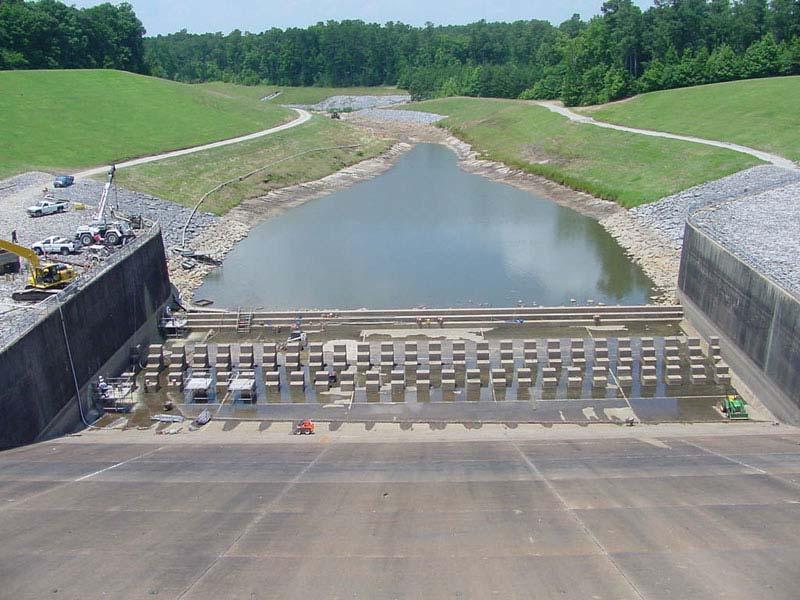
186 Stable Channels Lanes balance 186
187 187
188 Stable Channels Lanes balance Scour of channel bed and banks are typically main concerns Revetments designed through analysis of tractive force: Limiting shear stress Limiting velocity 188
189 Limiting Velocity 189
190 Limiting Velocity Plate
191 Chapter 3 Riprap Protection 191
Closed duct flows are full of fluid, have no free surface within, and are driven by a pressure gradient along the duct axis.
 OPEN CHANNEL FLOW Open channel flow is a flow of liquid, basically water in a conduit with a free surface. The open channel flows are driven by gravity alone, and the pressure gradient at the atmospheric
OPEN CHANNEL FLOW. One-dimensional - neglect vertical and lateral variations in velocity. In other words, Q v = (1) A. Figure 1. One-dimensional Flow
 A. Figure 1. One-dimensional Flow") OPEN CHANNEL FLOW Page 1 OPEN CHANNEL FLOW Open Channel Flow (OCF) is flow with one boundary exposed to atmospheric pressure. The flow is not pressurized and occurs because of gravity. Flow Classification
OPEN CHANNEL FLOW Page 1 OPEN CHANNEL FLOW Open Channel Flow (OCF) is flow with one boundary exposed to atmospheric pressure. The flow is not pressurized and occurs because of gravity. Flow Classification
Open Channel Flow Part 2. Ch 10 Young, notes, handouts
 Open Channel Flow Part 2 Ch 10 Young, notes, handouts Uniform Channel Flow Many situations have a good approximation d(v,y,q)/dx=0 Uniform flow Look at extended Bernoulli equation Friction slope exactly
Closed duct flows are full of fluid, have no free surface within, and are driven by a pressure gradient along the duct axis.
 OPEN CHANNEL FLOW Open channel flow is a flow of liquid, basically water in a conduit with a free surface. The open channel flows are driven by gravity alone, and the pressure gradient at the atmospheric
We will assume straight channels with simple geometries (prismatic channels) and steady state flow (in time).
 and steady state flow (in time).") 56 Review Drag & Lift Laminar vs Turbulent Boundary Layer Turbulent boundary layers stay attached to bodies longer Narrower wake! Lower pressure drag! 8. Open-Channel Flow Pipe/duct flow closed, full,
56 Review Drag & Lift Laminar vs Turbulent Boundary Layer Turbulent boundary layers stay attached to bodies longer Narrower wake! Lower pressure drag! 8. Open-Channel Flow Pipe/duct flow closed, full,
Hydraulics for Urban Storm Drainage
 Urban Hydraulics Hydraulics for Urban Storm Drainage Learning objectives: understanding of basic concepts of fluid flow and how to analyze conduit flows, free surface flows. to analyze, hydrostatic pressure
Uniform Channel Flow Basic Concepts Hydromechanics VVR090
 Uniform Channel Flow Basic Concepts Hydromechanics VVR090 ppt by Magnus Larson; revised by Rolf L Feb 2014 SYNOPSIS 1. Definition of Uniform Flow 2. Momentum Equation for Uniform Flow 3. Resistance equations
Uniform Channel Flow Basic Concepts. Definition of Uniform Flow
 Uniform Channel Flow Basic Concepts Hydromechanics VVR090 Uniform occurs when: Definition of Uniform Flow 1. The depth, flow area, and velocity at every cross section is constant 2. The energy grade line,
UNIFORM FLOW CRITICAL FLOW GRADUALLY VARIED FLOW
 UNIFORM FLOW CRITICAL FLOW GRADUALLY VARIED FLOW Derivation of uniform flow equation Dimensional analysis Computation of normal depth UNIFORM FLOW 1. Uniform flow is the flow condition obtained from a
Pressure Head: Pressure head is the height of a column of water that would exert a unit pressure equal to the pressure of the water.
 Design Manual Chapter - Stormwater D - Storm Sewer Design D- Storm Sewer Sizing A. Introduction The purpose of this section is to outline the basic hydraulic principles in order to determine the storm
Dr. Muhammad Ali Shamim ; Internal 652
 Dr. Muhammad Ali Shamim ali.shamim@uettaxila.edu.pk 051-904765; Internal 65 Channel Tranistions A channel transition is defined as change in channel cross section e.g. change in channel width and/or channel
Lateral Inflow into High-Velocity Channels
 Lateral Inflow into High-Velocity Channels by Richard L. Stockstill PURPOSE: This Coastal and Hydraulics Engineering Technical Note (CHETN) investigates lateral flow discharging into a high-velocity channel.
MODELING OF LOCAL SCOUR AROUND AL-KUFA BRIDGE PIERS Saleh I. Khassaf, Saja Sadeq Shakir
 ISSN 2320-9100 11 International Journal of Advance Research, IJOAR.org Volume 1, Issue 8,August 2013, Online: ISSN 2320-9100 MODELING OF LOCAL SCOUR AROUND AL-KUFA BRIDGE PIERS Saleh I. Khassaf, Saja Sadeq
NPTEL Quiz Hydraulics
 Introduction NPTEL Quiz Hydraulics 1. An ideal fluid is a. One which obeys Newton s law of viscosity b. Frictionless and incompressible c. Very viscous d. Frictionless and compressible 2. The unit of kinematic
Hydraulics and hydrology
 Hydraulics and hydrology - project exercises - Class 4 and 5 Pipe flow Discharge (Q) (called also as the volume flow rate) is the volume of fluid that passes through an area per unit time. The discharge
Review of pipe flow: Friction & Minor Losses
 ENVE 204 Lecture -1 Review of pipe flow: Friction & Minor Losses Assist. Prof. Neslihan SEMERCİ Marmara University Department of Environmental Engineering Important Definitions Pressure Pipe Flow: Refers
STEADY UNIFORM FLOW IN OPEN CHANNEL
 11/4/018 School of Environmental Engineering STEY UNIFORM FLOW IN OEN CHNNEL ZULKRNIN BIN HSSN COURSE OUTCOMES CO1: ble to analyze and design the steady flow in pipeline (O1) CO: ble to analyze and design
Open Channel Flow I - The Manning Equation and Uniform Flow COURSE CONTENT
 Open Channel Flow I - The Manning Equation and Uniform Flow Harlan H. Bengtson, PhD, P.E. COURSE CONTENT 1. Introduction Flow of a liquid may take place either as open channel flow or pressure flow. Pressure
compare to Mannings equation
 330 Fluid dynamics Density and viscosity help to control velocity and shear in fluids Density ρ (rho) of water is about 700 times greater than air (20 degrees C) Viscosity of water about 55 times greater
Hydraulics Part: Open Channel Flow
 Hydraulics Part: Open Channel Flow Tutorial solutions -by Dr. K.N. Dulal Uniform flow 1. Show that discharge through a channel with steady flow is given by where A 1 and A 2 are the sectional areas of
1.060 Engineering Mechanics II Spring Problem Set 8
 1.060 Engineering Mechanics II Spring 2006 Due on Monday, May 1st Problem Set 8 Important note: Please start a new sheet of paper for each problem in the problem set. Write the names of the group members
Hydromechanics: Course Summary
 Hydromechanics: Course Summary Hydromechanics VVR090 Material Included; French: Chapters to 9 and 4 + Sample problems Vennard & Street: Chapters 8 + 3, and (part of it) Roberson & Crowe: Chapter Collection
Chapter 10 Flow in Conduits
 Chapter 10 Flow in Conduits 10.1 Classifying Flow Laminar Flow and Turbulent Flow Laminar flow Unpredictable Turbulent flow Near entrance: undeveloped developing flow In developing flow, the wall shear
5. ROADSIDE AND MEDIAN CHANNELS
 5. ROADSIDE AND MEDIAN CHANNELS Roadside and median channels are open-channel systems which collect and convey stormwater from the pavement surface, roadside, and median areas. These channels may outlet
Basic Hydraulics. Rabi H. Mohtar ABE 325
 Basic Hydraulics Rabi H. Mohtar ABE 35 The river continues on its way to the sea, broken the wheel of the mill or not. Khalil Gibran The forces on moving body of fluid mass are:. Inertial due to mass (ρ
Flow in Open Channel Flow Conditions
 Civil Engineering Hydraulics Flow The graduate with a Science degree asks, "Why does it work?" The graduate with an Engineering degree asks, "How does it work?" The graduate with an Accounting degree asks,
MODELING FLUID FLOW IN OPEN CHANNEL WITH HORSESHOE CROSS SECTION
 July. 2. Vol. 7. No. 2 MODELING FLUID FLOW IN OPEN CHANNEL WITH HORSESHOE CROSS SECTION 1 J. JOMBA, 2 D.M.THEURI, 2 E. MWENDA, 2 C. CHOMBA ABSTRACT Flow in a closed conduit is regarded as open channel
THE EFFECT OF THICKNESS OF PILLAR IN THE CHANNEL BEND TO CHANGES THE COEFFICIENT OF SUPERELEVATION
 Journal Engineering Science and Technology Vol. 11, No. 5 (2016) 745-754 School Engineering, Taylor s University THE EFFECT OF THICKNESS OF PILLAR IN THE CHANNEL BEND TO CHANGES THE COEFFICIENT OF SUPERELEVATION
Open Channel Flow - General. Open Channel Flow
 Open Channel Flow - General Hydromechanics VVR090 Open Channel Flow Open channel: a conduit for flow which has a free surface Free surface: interface between two fluids of different density Characteristics
FE Fluids Review March 23, 2012 Steve Burian (Civil & Environmental Engineering)
") Topic: Fluid Properties 1. If 6 m 3 of oil weighs 47 kn, calculate its specific weight, density, and specific gravity. 2. 10.0 L of an incompressible liquid exert a force of 20 N at the earth s surface.
Topic: Fluid Properties 1. If 6 m 3 of oil weighs 47 kn, calculate its specific weight, density, and specific gravity. 2. 10.0 L of an incompressible liquid exert a force of 20 N at the earth s surface.
CEE 3310 Open Channel Flow, Nov. 26,
 CEE 3310 Open Channel Flow, Nov. 6, 018 175 8.10 Review Open Channel Flow Gravity friction balance. y Uniform Flow x = 0 z = S 0L = h f y Rapidly Varied Flow x 1 y Gradually Varied Flow x 1 In general
Presented by: Civil Engineering Academy
 Presented by: Civil Engineering Academy Open-Channel Flow Uniform Flow (See CERM Ch. 19) Characterized by constant depth volume, and cross section. It can be steady or unsteady Non-uniform Flow *Not on
Beaver Creek Corridor Design and Analysis. By: Alex Previte
 Beaver Creek Corridor Design and Analysis By: Alex Previte Overview Introduction Key concepts Model Development Design Accuracy Conclusion Refresh v = Beaver Creek Site = Wittenberg Introduction Low head
1-Reynold s Experiment
 Lect.No.8 2 nd Semester Flow Dynamics in Closed Conduit (Pipe Flow) 1 of 21 The flow in closed conduit ( flow in pipe ) is differ from this occur in open channel where the flow in pipe is at a pressure
Hydraulics. B.E. (Civil), Year/Part: II/II. Tutorial solutions: Pipe flow. Tutorial 1
, Year/Part: II/II. Tutorial solutions: Pipe flow. Tutorial 1") Hydraulics B.E. (Civil), Year/Part: II/II Tutorial solutions: Pipe flow Tutorial 1 -by Dr. K.N. Dulal Laminar flow 1. A pipe 200mm in diameter and 20km long conveys oil of density 900 kg/m 3 and viscosity
Hydraulics B.E. (Civil), Year/Part: II/II Tutorial solutions: Pipe flow Tutorial 1 -by Dr. K.N. Dulal Laminar flow 1. A pipe 200mm in diameter and 20km long conveys oil of density 900 kg/m 3 and viscosity
Guo, James C.Y. (1999). "Critical Flow Section in a Collector Channel," ASCE J. of Hydraulic Engineering, Vol 125, No. 4, April.
. Critical Flow Section in a Collector Channel, ASCE J. of Hydraulic Engineering, Vol 125, No. 4, April.") Guo, James C.Y. (1999). "Critical Flow Section in a Collector Channel," ASCE J. of Hydraulic Engineering, Vol 15, No. 4, April. CRITICAL FLOW SECTION IN A COLLECTOR CHANNEL By James C.Y. Guo, PhD, P.E.
Guo, James C.Y. (1999). "Critical Flow Section in a Collector Channel," ASCE J. of Hydraulic Engineering, Vol 15, No. 4, April. CRITICAL FLOW SECTION IN A COLLECTOR CHANNEL By James C.Y. Guo, PhD, P.E.
CIE4491 Lecture. Hydraulic design
 CIE4491 Lecture. Hydraulic design Marie-claire ten Veldhuis 19-9-013 Delft University of Technology Challenge the future Hydraulic design of urban stormwater systems Focus on sewer pipes Pressurized and
Chapter (3) Water Flow in Pipes
 Water Flow in Pipes") Chapter (3) Water Flow in Pipes Water Flow in Pipes Bernoulli Equation Recall fluid mechanics course, the Bernoulli equation is: P 1 ρg + v 1 g + z 1 = P ρg + v g + z h P + h T + h L Here, we want to study
Chapter (3) Water Flow in Pipes Water Flow in Pipes Bernoulli Equation Recall fluid mechanics course, the Bernoulli equation is: P 1 ρg + v 1 g + z 1 = P ρg + v g + z h P + h T + h L Here, we want to study
Open Channel Flow - General. Hydromechanics VVR090
 Open Channel Flow - General Hydromechanics VVR090 ppt by Magnus Larson; revised by Rolf L Jan 2014, Feb 2015 SYNOPSIS 1. Introduction and Applications 2. The History of Open Channel Flow 3. Flow Classification
FLOW IN CONDUITS. Shear stress distribution across a pipe section. Chapter 10
 Chapter 10 Shear stress distribution across a pipe section FLOW IN CONDUITS For steady, uniform flow, the momentum balance in s for the fluid cylinder yields Fluid Mechanics, Spring Term 2010 Velocity
A STUDY OF LOCAL SCOUR AT BRIDGE PIERS OF EL-MINIA
 A STUDY OF LOCAL SCOUR AT BRIDGE PIERS OF EL-MINIA Dr. Gamal A. Sallam 1 and Dr. Medhat Aziz 2 ABSTRACT Bridges are critical structures that require a substantial investment to construct and serve an important
Fluid Mechanics Prof. S.K. Som Department of Mechanical Engineering Indian Institute of Technology, Kharagpur
 Fluid Mechanics Prof. S.K. Som Department of Mechanical Engineering Indian Institute of Technology, Kharagpur Lecture - 42 Flows with a Free Surface Part II Good morning. I welcome you to this session
Hydraulics Prof. Dr. Arup Kumar Sarma Department of Civil Engineering Indian Institute of Technology, Guwahati
 Hydraulics Prof. Dr. Arup Kumar Sarma Department of Civil Engineering Indian Institute of Technology, Guwahati Module No. # 04 Gradually Varied Flow Lecture No. # 07 Rapidly Varied Flow: Hydraulic Jump
MATHEMATICAL MODELING OF FLUVIAL SEDIMENT DELIVERY, NEKA RIVER, IRAN. S.E. Kermani H. Golmaee M.Z. Ahmadi
 JOURNAL OF ENVIRONMENTAL HYDROLOGY The Electronic Journal of the International Association for Environmental Hydrology On the World Wide Web at http://www.hydroweb.com VOLUME 16 2008 MATHEMATICAL MODELING
LECTURE 9: Open channel flow: Uniform flow, best hydraulic sections, energy principles, Froude number
 LECTURE 9: Open channel flow: Uniform flow, best hydraulic sections, energy principles, Froude number Assist. Prof. Neslihan SEMERCİ Marmara University Department of Environmental Engineering Open channel
THE HYDRAULIC PERFORMANCE OF ORIENTED SPUR DIKE IMPLEMENTATION IN OPEN CHANNEL
 Tenth International Water Technology Conference, IWTC10 2006, Alexandria, Egypt 281 THE HYDRAULIC PERFORMANCE OF ORIENTED SPUR DIKE IMPLEMENTATION IN OPEN CHANNEL Karima Attia 1 and Gamal El Saied 2 1
Uniform Flow in Open Channels
 1 UNIT 2 Uniform Flow in Open Channels Lecture-01 Introduction & Definition Open-channel flow, a branch of hydraulics, is a type of liquid flow within a conduit with a free surface, known as a channel.
Chapter 6. Losses due to Fluid Friction
 Chapter 6 Losses due to Fluid Friction 1 Objectives ä To measure the pressure drop in the straight section of smooth, rough, and packed pipes as a function of flow rate. ä To correlate this in terms of
conservation of linear momentum 1+8Fr = 1+ Sufficiently short that energy loss due to channel friction is negligible h L = 0 Bernoulli s equation.
 174 Review Flow through a contraction Critical and choked flows The hydraulic jump conservation of linear momentum y y 1 = 1+ 1+8Fr 1 8.1 Rapidly Varied Flows Weirs 8.1.1 Broad-Crested Weir Consider the
Turbulence is a ubiquitous phenomenon in environmental fluid mechanics that dramatically affects flow structure and mixing.
 Turbulence is a ubiquitous phenomenon in environmental fluid mechanics that dramatically affects flow structure and mixing. Thus, it is very important to form both a conceptual understanding and a quantitative
12d Model. Civil and Surveying Software. Version 7. Drainage Analysis Module Hydraulics. Owen Thornton BE (Mech), 12d Model Programmer
, 12d Model Programmer") 1d Model Civil and Surveying Sotware Version 7 Drainage Analysis Module Hydraulics Owen Thornton BE (Mech), 1d Model Programmer owen.thornton@1d.com 9 December 005 Revised: 10 January 006 8 February 007
1d Model Civil and Surveying Sotware Version 7 Drainage Analysis Module Hydraulics Owen Thornton BE (Mech), 1d Model Programmer owen.thornton@1d.com 9 December 005 Revised: 10 January 006 8 February 007
Lecture Note for Open Channel Hydraulics
 Chapter -one Introduction to Open Channel Hydraulics 1.1 Definitions Simply stated, Open channel flow is a flow of liquid in a conduit with free space. Open channel flow is particularly applied to understand
7. Basics of Turbulent Flow Figure 1.
 1 7. Basics of Turbulent Flow Whether a flow is laminar or turbulent depends of the relative importance of fluid friction (viscosity) and flow inertia. The ratio of inertial to viscous forces is the Reynolds
Pipe Flow. Lecture 17
 Pipe Flow Lecture 7 Pipe Flow and the Energy Equation For pipe flow, the Bernoulli equation alone is not sufficient. Friction loss along the pipe, and momentum loss through diameter changes and corners
Department of Hydro Sciences, Institute for Urban Water Management. Urban Water
 Department of Hydro Sciences, Institute for Urban Water Management Urban Water 1 Global water aspects Introduction to urban water management 3 Basics for systems description 4 Water transport 5 Matter
P10.5 Water flows down a rectangular channel that is 4 ft wide and 3 ft deep. The flow rate is 15,000 gal/min. Estimate the Froude number of the flow.
 P10.5 Water flows down a rectangular channel that is 4 ft wide and ft deep. The flow rate is 15,000 gal/min. Estimate the Froude number of the flow. Solution: Convert the flow rate from 15,000 gal/min
REE 307 Fluid Mechanics II. Lecture 1. Sep 27, Dr./ Ahmed Mohamed Nagib Elmekawy. Zewail City for Science and Technology
 REE 307 Fluid Mechanics II Lecture 1 Sep 27, 2017 Dr./ Ahmed Mohamed Nagib Elmekawy Zewail City for Science and Technology Course Materials drahmednagib.com 2 COURSE OUTLINE Fundamental of Flow in pipes
Gradually Varied Flow I+II. Hydromechanics VVR090
 Gradually Varied Flow I+II Hydromechanics VVR090 Gradually Varied Flow Depth of flow varies with longitudinal distance. Occurs upstream and downstream control sections. Governing equation: dy dx So Sf
FACULTY OF CHEMICAL & ENERGY ENGINEERING FLUID MECHANICS LABORATORY TITLE OF EXPERIMENT: MINOR LOSSES IN PIPE (E4)
") FACULTY OF CHEMICAL & ENERGY ENGINEERING FLUID MECHANICS LABORATORY TITLE OF EXPERIMENT: MINOR LOSSES IN PIPE (E4) 1 1.0 Objectives The objective of this experiment is to calculate loss coefficient (K
FACULTY OF CHEMICAL & ENERGY ENGINEERING FLUID MECHANICS LABORATORY TITLE OF EXPERIMENT: MINOR LOSSES IN PIPE (E4) 1 1.0 Objectives The objective of this experiment is to calculate loss coefficient (K
OPEN CHANNEL FLOW. Computer Applications. Numerical Methods and. Roland Jeppson. CRC Press UNIVERSITATSB'BUOTHEK TECHNISCHE. INFORMATlONSBiBUOTHEK
 OPEN CHANNEL FLOW Numerical Methods and Computer Applications Roland Jeppson TECHNISCHE INFORMATlONSBiBUOTHEK UNIVERSITATSB'BUOTHEK HANNOVER Si. i. CRC Press Taylor &.Francis Group Boca Raton London New
Created by Simpo PDF Creator Pro (unregistered version)
") 2 nd Semester TRANSITIONS STRUCTURES 1 of 9 A transition is a local change in cross-section which produces a variation of flow from one uniform state to another due to the change in cross sections of channels.
2 nd Semester TRANSITIONS STRUCTURES 1 of 9 A transition is a local change in cross-section which produces a variation of flow from one uniform state to another due to the change in cross sections of channels.
How to Design Bendway Weirs
 How to Design Bendway Weirs Project Background U.S. Bureau of Reclamation: Middle Rio Grande Channel Maintenance Program 29-Mile Study Reach: Cochiti Dam to Bernalillo Geomorphic Changes Due to Dam Construction
Advanced Hydraulics Prof. Dr. Suresh A. Kartha Department of Civil Engineering Indian Institute of Technology, Guwahati
 Advanced Hydraulics Prof. Dr. Suresh A. Kartha Department of Civil Engineering Indian Institute of Technology, Guwahati Module - 2 Uniform Flow Lecture - 1 Introduction to Uniform Flow Good morning everyone,
1. Open Channel Hydraulics
 Open Channel Flow. Open Channel Hydraulics.... Definition and differences between pipe flow and open channel flow.... Types of flow.... Properties of open channels...4.4 Fundamental equations... 5.4. The
Water Flow in Open Channels
 The Islamic Universit of Gaza Facult of Engineering Civil Engineering Department Hdraulics - ECIV 33 Chapter 6 Water Flow in Open Channels Introduction An open channel is a duct in which the liquid flows
Evaluation of Scour Depth around Bridge Piers with Various Geometrical Shapes
 Evaluation of Scour Depth around Bridge Piers with Various Geometrical Shapes Dr. P. D. Dahe * Department of Civil Engineering, SGGSIE&T, Vishnupuri, Nanded (Maharashtra) S. B. Kharode Department of Civil
Geology 550 Spring 2005 LAB 3: HYDRAULICS OF PRAIRIE CREEK
 Geology 550 Spring 2005 LAB 3: HYDRAULICS OF PRAIRIE CREEK Objectives: 1. To examine the distribution of velocity in a stream channel 2. To characterize the state of flow using dimensionless variables
A note on critical flow section in collector channels
 Sādhan ā, Vol. 26, Part 5, October 2001, pp. 439 445. Printed in India A note on critical flow section in collector channels 1. Introduction SUBHASISH DEY Department of Civil Engineering, Indian Institute
Hydraulics of bendway weirs
 River Basin Management IV 389 Hydraulics of bendway weirs C. Thornton 1, S. Abt 1, D. Baird 2 & R. Padilla 3 1 Colorado State University, Fort Collins, CO, USA 2 U.S. Bureau of Reclamation, Denver, CO,
Lesson 6 Review of fundamentals: Fluid flow
 Lesson 6 Review of fundamentals: Fluid flow The specific objective of this lesson is to conduct a brief review of the fundamentals of fluid flow and present: A general equation for conservation of mass
FLUID MECHANICS. Dynamics of Viscous Fluid Flow in Closed Pipe: Darcy-Weisbach equation for flow in pipes. Major and minor losses in pipe lines.
 FLUID MECHANICS Dynamics of iscous Fluid Flow in Closed Pipe: Darcy-Weisbach equation for flow in pipes. Major and minor losses in pipe lines. Dr. Mohsin Siddique Assistant Professor Steady Flow Through
EXAMPLES (SEDIMENT TRANSPORT) AUTUMN 2018
 AUTUMN 2018") EXAMPLES (SEDIMENT TRANSPORT) AUTUMN 2018 Q1. Using Cheng s formula estimate the settling velocity of a sand particle of diameter 1 mm in: (a) air; (b) water. Q2. Find the critical Shields parameter diameter
EXAMPLES (SEDIMENT TRANSPORT) AUTUMN 2018 Q1. Using Cheng s formula estimate the settling velocity of a sand particle of diameter 1 mm in: (a) air; (b) water. Q2. Find the critical Shields parameter diameter
An overview of the Hydraulics of Water Distribution Networks
 An overview of the Hydraulics of Water Distribution Networks June 21, 2017 by, P.E. Senior Water Resources Specialist, Santa Clara Valley Water District Adjunct Faculty, San José State University 1 Outline
VARIED FLOW IN OPEN CHANNELS
 Chapter 15 Open Channels vs. Closed Conduits VARIED FLOW IN OPEN CHANNELS Fluid Mechanics, Spring Term 2011 In a closed conduit there can be a pressure gradient that drives the flow. An open channel has
Open Channel Hydraulics I - Uniform Flow
 PDHonline Course H138 (2 PDH) Open Channel Hydraulics I - Uniform Flow Instructor: Harlan H. Bengtson, Ph.D., PE 2012 PDH Online PDH Center 5272 Meadow Estates Drive Fairfax, VA 22030-6658 Phone & Fax:
LOSSES DUE TO PIPE FITTINGS
 LOSSES DUE TO PIPE FITTINGS Aim: To determine the losses across the fittings in a pipe network Theory: The resistance to flow in a pipe network causes loss in the pressure head along the flow. The overall
CHAPTER 2- BACKGROUND. INVESTIGATIONS OF COMPOSITE ROUGHNESS COEFFICIENT IN A RIVER WITH LOW FLOW
 2. Background 2.1 Introduction The estimation of resistant coefficient and hence discharge capacity in a channel or river is one of the fundamental problems facing river engineers. When applying Manning
EXPERIMENT No.1 FLOW MEASUREMENT BY ORIFICEMETER
 EXPERIMENT No.1 FLOW MEASUREMENT BY ORIFICEMETER 1.1 AIM: To determine the co-efficient of discharge of the orifice meter 1.2 EQUIPMENTS REQUIRED: Orifice meter test rig, Stopwatch 1.3 PREPARATION 1.3.1
Chapter 8: Flow in Pipes
 Objectives 1. Have a deeper understanding of laminar and turbulent flow in pipes and the analysis of fully developed flow 2. Calculate the major and minor losses associated with pipe flow in piping networks
28.2 Classification of Jumps
 28.2 Classification of Jumps As mentioned earlier, the supercritical flow Froude number influences the characteristics of the hydraulic jump. Bradley and Peterka, after extensive experimental investigations,
Calculation of Stream Discharge Required to Move Bed Material
 Calculation of Stream Discharge Required to Move Bed Material Objective: Students will map two sections of a stream and calculate the depth, velocity, and discharge of flows required to move the stream
Viscous Flow in Ducts
 Dr. M. Siavashi Iran University of Science and Technology Spring 2014 Objectives 1. Have a deeper understanding of laminar and turbulent flow in pipes and the analysis of fully developed flow 2. Calculate
Prof. B.S. Thandaveswara. Superelevation is defined as the difference in elevation of water surface between inside (1)
") 36.4 Superelevation Superelevation is defined as the difference in elevation of water surface between inside and outside wall of the bend at the same section. y=y y (1) 1 This is similar to the road banking
36.4 Superelevation Superelevation is defined as the difference in elevation of water surface between inside and outside wall of the bend at the same section. y=y y (1) 1 This is similar to the road banking
STEADY FLOW THROUGH PIPES DARCY WEISBACH EQUATION FOR FLOW IN PIPES. HAZEN WILLIAM S FORMULA, LOSSES IN PIPELINES, HYDRAULIC GRADE LINES AND ENERGY
 STEADY FLOW THROUGH PIPES DARCY WEISBACH EQUATION FOR FLOW IN PIPES. HAZEN WILLIAM S FORMULA, LOSSES IN PIPELINES, HYDRAULIC GRADE LINES AND ENERGY LINES 1 SIGNIFICANCE OF CONDUITS In considering the convenience
UNIT II Real fluids. FMM / KRG / MECH / NPRCET Page 78. Laminar and turbulent flow
 UNIT II Real fluids The flow of real fluids exhibits viscous effect that is they tend to "stick" to solid surfaces and have stresses within their body. You might remember from earlier in the course Newtons
Estimating Scour. CIVE 510 October 21 st, 2008
 Estimating Scour CIVE 510 October 21 st, 2008 1 Causes of Scour 2 Site Stability 3 Mass Failure Downward movement of large and intact masses of soil and rock Occurs when weight on slope exceeds the shear
DEPARTMENT OF CIVIL AND ENVIRONMENTAL ENGINEERING Urban Drainage: Hydraulics. Solutions to problem sheet 2: Flows in open channels
 DEPRTMENT OF CIVIL ND ENVIRONMENTL ENGINEERING Urban Drainage: Hydraulics Solutions to problem sheet 2: Flows in open channels 1. rectangular channel of 1 m width carries water at a rate 0.1 m 3 /s. Plot
EXPERIMENT II - FRICTION LOSS ALONG PIPE AND LOSSES AT PIPE FITTINGS
 MM 30 FLUID MECHANICS II Prof. Dr. Nuri YÜCEL Yrd. Doç. Dr. Nureddin DİNLER Arş. Gör. Dr. Salih KARAASLAN Arş. Gör. Fatih AKTAŞ EXPERIMENT II - FRICTION LOSS ALONG PIPE AND LOSSES AT PIPE FITTINGS A. Objective:
Experiment (4): Flow measurement
: Flow measurement") Experiment (4): Flow measurement Introduction: The flow measuring apparatus is used to familiarize the students with typical methods of flow measurement of an incompressible fluid and, at the same time
Experiment (4): Flow measurement Introduction: The flow measuring apparatus is used to familiarize the students with typical methods of flow measurement of an incompressible fluid and, at the same time
Chapter 8: Flow in Pipes
 8-1 Introduction 8-2 Laminar and Turbulent Flows 8-3 The Entrance Region 8-4 Laminar Flow in Pipes 8-5 Turbulent Flow in Pipes 8-6 Fully Developed Pipe Flow 8-7 Minor Losses 8-8 Piping Networks and Pump
Chapter (3) Water Flow in Pipes
 Water Flow in Pipes") Chapter (3) Water Flow in Pipes Water Flow in Pipes Bernoulli Equation Recall fluid mechanics course, the Bernoulli equation is: P 1 ρg + v 1 g + z 1 = P ρg + v g + z h P + h T + h L Here, we want to study
Chapter (3) Water Flow in Pipes Water Flow in Pipes Bernoulli Equation Recall fluid mechanics course, the Bernoulli equation is: P 1 ρg + v 1 g + z 1 = P ρg + v g + z h P + h T + h L Here, we want to study
P = 2Rθ. The previous Manning formulas are used to predict V o and Q for uniform flow when the above expressions are substituted for A, P, and R h.
 Uniform Flow in a Partly Full, Circular Pipe Fig. 10.6 shows a partly full, circular pipe with uniform flow. Since frictional resistance increases with wetted perimeter, but volume flow rate increases
Module 2. The Science of Surface and Ground Water. Version 2 CE IIT, Kharagpur
 Module The Science of Surface and Ground Water Lesson Sediment Dynamics in Alluvial Rivers and Channels Instructional Objectives On completion of this lesson, the student shall be able to learn the following:.
Q = α n AR2/3 h S1/2 0. bd 2d + b d if b d. 0 = ft1/3 /s
 CEE 330 Open Channel Flow, Nov., 00 7 8.8 Review Open Channel Flow Gravity friction balance. In general we take an energy equation approach. y Uniform Flow x = 0 z = S 0L = h f where we could find h f
Stable Channel Analysis and Design
 PDHonline Course H145 (4 PDH) Stable Channel Analysis and Design Instructor: Joseph V. Bellini, PE, PH, DWRE, CFM 2012 PDH Online PDH Center 5272 Meadow Estates Drive Fairfax, VA 22030-6658 Phone & Fax:
ME 305 Fluid Mechanics I. Part 8 Viscous Flow in Pipes and Ducts. Flow in Pipes and Ducts. Flow in Pipes and Ducts (cont d)
") ME 305 Fluid Mechanics I Flow in Pipes and Ducts Flow in closed conduits (circular pipes and non-circular ducts) are very common. Part 8 Viscous Flow in Pipes and Ducts These presentations are prepared
ME 305 Fluid Mechanics I Flow in Pipes and Ducts Flow in closed conduits (circular pipes and non-circular ducts) are very common. Part 8 Viscous Flow in Pipes and Ducts These presentations are prepared
y 2 = 1 + y 1 This is known as the broad-crested weir which is characterized by:
 CEE 10 Open Channel Flow, Dec. 1, 010 18 8.16 Review Flow through a contraction Critical and choked flows The hydraulic jump conservation of linear momentum y = 1 + y 1 1 + 8Fr 1 8.17 Rapidly Varied Flows
Chapter 3.8: Energy Dissipators. By Dr. Nuray Denli Tokyay
 Chapter 3.8: Energy Dissipators By Dr. Nuray Denli Tokyay 3.1 Introduction A stilling basin is a short length of paved channel placed at the foot of a spillway or any other source of supercritical flow
Open Channel Hydraulics III - Sharpcrested
 PDHonline Course H140 (2 PDH) Open Channel Hydraulics III - Sharpcrested Weirs Instructor: Harlan H. Bengtson, Ph.D., PE 2012 PDH Online PDH Center 5272 Meadow Estates Drive Fairfax, VA 22030-6658 Phone
Reynolds, an engineering professor in early 1880 demonstrated two different types of flow through an experiment:
 7 STEADY FLOW IN PIPES 7.1 Reynolds Number Reynolds, an engineering professor in early 1880 demonstrated two different types of flow through an experiment: Laminar flow Turbulent flow Reynolds apparatus