Chapter 6. Losses due to Fluid Friction
|
|
|
- Verity Gray
- 5 years ago
- Views:
Transcription
1 Chapter 6 Losses due to Fluid Friction 1
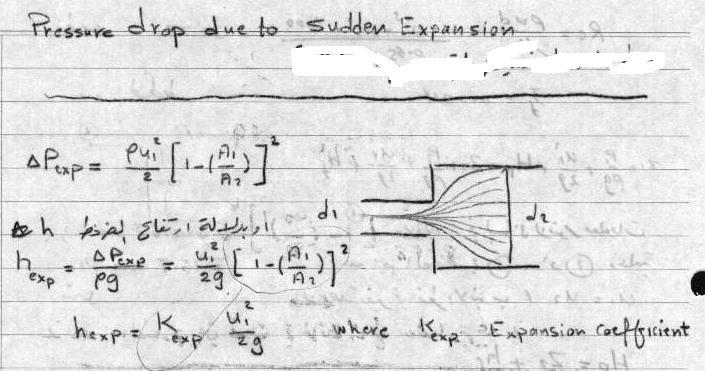
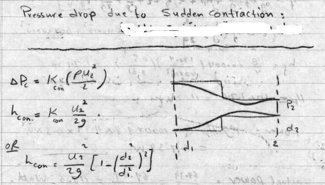
2 Objectives ä To measure the pressure drop in the straight section of smooth, rough, and packed pipes as a function of flow rate. ä To correlate this in terms of the friction factor and Reynolds number. ä To compare results with available theories and correlations. ä To determine the influence of pipe fittings on pressure drop ä To show the relation between flow area, pressure drop and loss as a function of flow rate for Venturi meter and Orifice meter.
3 Losses due to Friction Mechanical energy equation between locations 1 and in the absence of shaft work: P1 P V1 V ( ) ( ) ( z1 z) g g g g For flow in a horizontal pipe and no diameter change (V1=V), then : F P 1 P Hagen-Poiseuille Law-E5.10 F Q x 18 4 D o OR Or F/g= h Loss = 18μQL/(πρgD 4 ) and F/g F g hloss Because of (5.4) : F 4x D (6.13) (6.14) h L w where Thus, the shear stress at the wall is responsible for the losses due to friction F u =Friction head/unit mass P1 P g F in J/kg 3 Q m
4 Losses due to Friction Total head loss, h L (=F/g), is regarded as the sum of major losses and minor losses h L major, due to frictional effects in fully developed flow in constant area tubes, h L minor, resulting from entrance, fitting, area changes, and so on. 4
5 Losses due to Friction/The Friction Factor In order to determine an expression for the losses due to friction we must resort to experimentation. F L V D By introducing the friction factor, f: where L=length of the pipe, D=diameter of the pipe, V=velocity, F f L V D. (6.15) F P 1 P where f ( L / F D)( V / ) or f P( D / L) V / f is called Darcy friction factor 5
6 Friction Factor now later ( P gz V ) P work P The Darcy friction factor f is defined as f P( D / L) V / We know the wall shear stress f V w / and L 0 τ w P D 4 (E6-1) L, major P L The friction factor is the ratio between wall shear stress and flow inertial force. L P P L, min or 6
7 ( P gz Major Loss and Friction Factor V ) P work P L 0 P With the introduction of friction factor, we can calculate major loss by L P L, major P L, min or P L, Major f L D V (E6-) Friction factor Pipe geometry factor Dynamic pressure Therefore, our job now is find the friction factor for various flows. 7
8 Friction Factor - Laminar Pipe Flow For a pipe with a length of L, the pressure gradient is constant, the pressure drop based on Hagen-Poiseuille Law, P 3VL / D Divided both sides by the dynamic pressure V / and L/D f P( D / L) 3VL / D D 64 V / V / L VD 64 Re We have f 64 Re 8
9 Major Loss and Friction Factor The mechanical energy equation can be written in terms of heads : P1 P V1 V ( ) ( ) ( z1 z) g g g g W shaft mg h Loss (6.17) L V f L, D g h Major Knowledge of the friction factor allows us to estimate the loss term in the energy equation. This head loss can also be calculated using H-B equation 9
10 10
11 Example 1 losses in 11
12 1
13 Example 13
14 14
15 Case : Turbulent Flow When fluid flow at higher flow rates, the streamlines are not steady, not straight and the flow is not laminar. Generally, the flow field will vary in both space and time with fluctuations that comprise "turbulence When the flow is turbulent the velocity and pressure fluctuate very rapidly. The velocity components at a point in a turbulent flow field fluctuate about a mean value. Time-averaged velocity profile can be expressed in terms of the power law equation, n =7 is a good approximation. u V max r 1 R 1/ n 15
16 Friction Factor-Turbulent Pipe Flow For a laminar flow, the friction factor can be analytically derived. It is impossible to do so for a turbulent flow so that we can only obtain the friction factor from empirical results. For turbulent flow, it is impossible to analytically derive the friction factor f, which can ONLY be obtained from experimental data. In addition, most pipes, except glass tubing, have rough surfaces. The pipe surface roughness is quantified by a dimensionless number, relative pipe roughness (ε / D ), where ε is pipe roughness and D is pipe diameter. For laminar pipe flow, the flow is dominated by viscous effects hence surface roughness is not a consideration. However, for turbulent flow, the surface roughness may protrude beyond the laminar sublayer and affect the flow to a certain degree. Therefore, the friction factor f can be generally written as a function of Reynolds number and pipe relative roughness There are several theoretical models available for the prediction of shear stresses in turbulent flow. 16
17 Surface Roughness Additional dimensionless group /D need to be characterize Thus more than one curve on friction factor- Reynolds number plot Fanning diagram or Moody diagram Depending on the laminar region. If, at the lowest Reynolds numbers, the laminar portion corresponds to f =16/Re Fanning Chart (or f = 64/Re Moody chart) 17
18 Friction Factor and Pipe Roughness Most pipes, except glass tubing, have rough surfaces - Pipe surface roughness, - Relative pipe roughness, / D The surface roughness may affect the friction factor. Generally, we have f (Re, ) D 18
19 Pipe Surface Roughness 19
20 Friction Factor of Turbulent Flow If the surface protrusions are within the viscous layer, the pipe is hydraulically smooth; f Re 1/ 4 If the surface protrusions extend into the buffer layer, f is a function of both Re and /D; f (Re, D) For large protrusions into the turbulent core, f is only a function of /D. f ( D) 0
21 Friction Factor for Smooth, Transition, f P L Smooth pipe, Re>3000 and Rough Turbulent flow D U Rough pipe, [ (D/ε)/(Re ƒ) <0.01] Transition function for both smooth and rough pipe Or 1 f 1 f * logre* f 0.4 f 0.079Re 0.5 f 4.0 * log D * log D D/ * log 4.67 Re f 1 1

22 Fanning Diagram 1 f 4.0 * log D D/ * log 4.67 Re f 1 1 f 4.0 * log D.8 f =16/Re

23 Friction Factor The Moody Chart 3
24 Example: Comparison of Laminar or Turbulent pressure Drop Air under standard conditions flows through a 4.0-mmdiameter drawn tubing with an average velocity of V = 50 m/s. For such conditions the flow would normally be turbulent. However, if precautions are taken to eliminate disturbances to the flow (the entrance to the tube is very smooth, the air is dust free, the tube does not vibrate, etc.), it may be possible to maintain laminar flow. (a) Determine the pressure drop in a 0.1-m section of the tube if the flow is laminar. (b) Repeat the calculations if the flow is turbulent. Straight and horizontal pipe and same diameters give same velocity: Z 1 =Z =0 V 1 =V and thus p / g h Loss 4
25 Solution 1/ Under standard temperature and pressure conditions =1.3kg/m 3, μ= Ns/m The Reynolds number R e VD /... 13,700 Turbulent flow If the flow were laminar and using Darcy friction f=64/re=` = p f 1 V kPa D If the flow were laminar and using Fanning friction 1 p 4 f V kPa D F=16/Re=` =
26 Solution / If the flow were turbulent From Moody chart f=φ(re, smooth pipe) =0.08 p f 1 V kPa D From Fanning chart f=φ(re, smooth pipe) = p 4 f V kPa D 6
27 Example Straight and horizontal pipe and same diameters give same velocity: Z 1 =Z =0 V 1 =V and thus p gh Loss pump pressure 7
28 8
29 9
30 Example 0.04 m 30
31 31
32 3
33 f 0.079Re 0.5 for fanning 33
34 Example: Determine Head Loss Crude oil at 140 F with γ=53.7 lb/ft 3 and μ= lb s/ft (about four times the viscosity of water) is pumped across Alaska through the Alaska pipeline, a 799-mile-along, 4-ft-diameter steel pipe, at a maximum rate of Q =.4 million barrel/day = 117ft 3 /s, or V=Q/A=9.31 ft/s. Determine the horsepower needed for the pumps that drive this large system. 34
 Minor losses are negligible because of the large lengthto-diameter ratio of the relatively straight, uninterrupted pipe. V hl hp f.")
35 Solution 1/ The energy equation between points (1) and () p 1 V1 p V z1 hp z hl g g h P is the head provided to the oil by the pump. Assume that z 1 =z, p 1 =p =V 1 =V =0 (large, open tank) Minor losses are negligible because of the large lengthto-diameter ratio of the relatively straight, uninterrupted pipe. V hl hp f ft D g f=0.014 from chart ε/d=( ft)/(4ft), Re=.. 35
36 Solution / The actual power supplied to the fluid power=q P =Qρgh unit of power (SI): Watt =N.m/s=J/s Power 1hp gqh P hp 550 ftlb / s 36
 add to the overall head loss of the system.")
37 Minor Losses 1/5 Most pipe systems consist of considerably more than straight pipes. These additional components (valves, bends, tees, and the like) add to the overall head loss of the system. Such losses are termed MINOR LOSS. The flow pattern through a valve 37


38 90 0 Bend 90 0 Elbow 45 0 Elbow Tees-line flow Tees-branch flow 38


39 Valves Globe valve Angle valve Gate valve Ball valve 39
40 Minor Losses /5 The theoretical analysis to predict the details of flow pattern (through these additional components) is not, as yet, possible. The head loss information for essentially all components is given in dimensionless form and based on experimental data. The most common method used to determine these head losses or pressure drops is to specify the loss coefficient, K L 40
41 Minor Losses 3/5 K L h V L min or / g p 1 V p Minor losses are sometimes given in terms of an equivalent length eq K L h 1 L V min or eq K K L L D f V g The actual value of K L is strongly dependent on the geometry of the component considered. It may also dependent on the fluid properties. That is f eq D V g K (geometry,re) L 41
42 Minor Losses 4/5 For many practical applications the Reynolds number is large enough so that the flow through the component is dominated by inertial effects, with viscous effects being of secondary importance. In a flow that is dominated by inertia effects rather than viscous effects, it is usually found that pressure drops and head losses correlate directly with the dynamic pressure. This is the reason why the friction factor for very large Reynolds number, fully developed pipe flow is independent of the Reynolds number. 4
43 Minor Losses 5/5 This is true for flow through pipe components. Thus, in most cases of practical interest the loss coefficients for components are a function of geometry only, K (geometry ) L 43
 sharp-edged, K L = 0.5 (c) slightly rounded, K L = 0. (d) well-rounded, K L = 0.")
44 Minor Losses Coefficient For Example Entrance flow Entrance flow condition and loss coefficient (a) re-entrant, K L = 0.8 (b) sharp-edged, K L = 0.5 (c) slightly rounded, K L = 0. (d) well-rounded, K L =
45 Summary of Minor Losses Major losses: Associated with the friction in the straight portions of the pipes Minor losses: Due to additional components (pipe fittings, valves, bends, tees etc.) and to changes in flow area (contractions or expansions) Method 1: We try to express the head loss due to minor losses in terms of a loss coefficient, K L : F g minor losses K L V g Values of K L can be found in the literature (for example, see Table next ppt, for losses due to pipe components. 45
46 Minor Losses Component Elbows K L Regular 90, flanged 0.3 Regular 90, threaded 1.5 Long radius 90, flanged 0. Long radius 90, threaded 0.7 Long radius 45, flanged 0. Regular 45, threaded return bends 180 return bend, threaded return bend, flanged 1.5 Tees Line flow, flanged 0. Line flow, threaded 0.9 Branch flow, flanged 1.0 Branch flow, threaded.0 Component K L Union, threaded 0.8 Valves Globe, fully open 10 Angle, fully open Gate, fully open 0.15 Gate, ¼ closed 0.6 Gate, ½ closed.1 Gate, ¾ closed 17 Ball valve, fully open 0.05 Ball valve, 1/3 closed 5.5 Ball valve, /3 closed 10 46
47 47 Minor Losses The mechanical energy equation can be written: g V K g V D L f mg W z z g V g V g P g P L shaft ) ( ) ( ) ( (6.)
48 48 Minor Losses Method : Using the concept of equivalent length, which is the equivalent length of pipe which would have the same friction effect as the fitting. Values of equivalent length (L/D) can be found in the literature g V D L f mg W z z g V g V g P g P equiv shaft ) ( ) ( ) ( (6.3)
49 Example: Determine Pressure Drop Water at 60 F flows from the basement to the second floor through the 0.75-in. diameter copper pipe (a drawn tubing) at a rate of Q = 1.0 gal/min (= ft 3 /s) and exits through a faucet of diameter 0.50 in. as shown in Figure Determine the pressure at point (1) if: (a) all losses are neglected, (b) the only losses included are major losses, or (c) all losses are included. 49
50 V 1 Solution 1/4 Q A ft / s 5 lb s / ft The energy equation 1.94slug / ft Re VD / The flow is turbulent p1 g V1 p V z1 z g g g p h L z 1 (V V ) h 1 1 L z 1 V 0,z Q / A 0ft,p 0(free ft / s jet) Head loss is different for each of the three cases. 50
51 Solution /4 (a) If all losses are neglected (h L =0) 1 p1 z (V V1 ) lb /ft 10.7psi (b) If the only losses included are the major losses, the head loss is h V1 f L D g / D chart Re f = ( 60 ft) V1 p1 z ( V V1 ) 4f lb / ft 1. 3psi D 51
52 Solution 3/4 (c) If major and minor losses are included p 1 z 1 ( V V 1 ) f D V1 g K L V p 1 1.3psi 1.3psi K L V (1.94slugs / ft 3 ) (8.70 ft / s) [10 4(1.5) ] p 1 1.3psi 9.17psi 30.5psi 5
53 53
54 54

55 Noncircular Ducts The empirical correlations for pipe flow may be used for computations involving noncircular ducts, provided their cross sections are not too exaggerated. The correlation for turbulent pipe flow are extended for use with noncircular geometries by introducing the hydraulic diameter, D h, defined as D h 4A P Where A is crosssectional area, and P is wetted perimeter. 55
56 Noncircular Ducts 3/4 The friction factor can be written as f=c/re h, where the constant C depends on the particular shape of the duct, and Re h is the Reynolds number based on the hydraulic diameter. Re V Dh The hydraulic diameter is also used in the definition of the friction factor, h, and the relative L f ( / Dh)(V / g) roughness /D h. 56
57 Define hydraulic diameter, D h : Non circular conduits D h 4 x (cross sectional area) wetted perimeter Then use Reynolds number based on hydraulic diameter, D h : Re V Dh 57
58 58 Non circular conduits Pipe of circular cross-section D D 4 D 4 D h Annulus (inside diameter D 1, outside D ) h D D D D 4 D 4 D 4 D Rectangular conduit (area ab) b a ab b a (ab) 4 D h
59 Example Solved before 59
60 60

61 Multiple Pipe Systems Pipes in series Q 1 Q Q 3 F L AB F L 1 F L F L 3 61

62 Multiple Pipe Systems Parallel pipes Q F L Q 1 F Q F 1 L L3 Q 3 6
Chapter 6. Losses due to Fluid Friction
 Chapter 6 Losses due to Fluid Friction 1 Objectives To measure the pressure drop in the straight section of smooth, rough, and packed pipes as a function of flow rate. To correlate this in terms of the
ME 305 Fluid Mechanics I. Part 8 Viscous Flow in Pipes and Ducts. Flow in Pipes and Ducts. Flow in Pipes and Ducts (cont d)
") ME 305 Fluid Mechanics I Flow in Pipes and Ducts Flow in closed conduits (circular pipes and non-circular ducts) are very common. Part 8 Viscous Flow in Pipes and Ducts These presentations are prepared
ME 305 Fluid Mechanics I Flow in Pipes and Ducts Flow in closed conduits (circular pipes and non-circular ducts) are very common. Part 8 Viscous Flow in Pipes and Ducts These presentations are prepared
Reynolds, an engineering professor in early 1880 demonstrated two different types of flow through an experiment:
 7 STEADY FLOW IN PIPES 7.1 Reynolds Number Reynolds, an engineering professor in early 1880 demonstrated two different types of flow through an experiment: Laminar flow Turbulent flow Reynolds apparatus
Chapter 10 Flow in Conduits
 Chapter 10 Flow in Conduits 10.1 Classifying Flow Laminar Flow and Turbulent Flow Laminar flow Unpredictable Turbulent flow Near entrance: undeveloped developing flow In developing flow, the wall shear
Chapter 8: Flow in Pipes
 Objectives 1. Have a deeper understanding of laminar and turbulent flow in pipes and the analysis of fully developed flow 2. Calculate the major and minor losses associated with pipe flow in piping networks
PIPING SYSTEMS. Pipe and Tubing Standards Sizes for pipes and tubes are standardized. Pipes are specified by a nominal diameter and a schedule number.
 PIPING SYSTEMS In this chapter we will review some of the basic concepts associated with piping systems. Topics that will be considered in this chapter are - Pipe and tubing standards - Effective and hydraulic
Hydraulics and hydrology
 Hydraulics and hydrology - project exercises - Class 4 and 5 Pipe flow Discharge (Q) (called also as the volume flow rate) is the volume of fluid that passes through an area per unit time. The discharge
ME 305 Fluid Mechanics I. Chapter 8 Viscous Flow in Pipes and Ducts
 ME 305 Fluid Mechanics I Chapter 8 Viscous Flow in Pipes and Ducts These presentations are prepared by Dr. Cüneyt Sert Department of Mechanical Engineering Middle East Technical University Ankara, Turkey
Chapter 8: Flow in Pipes
 8-1 Introduction 8-2 Laminar and Turbulent Flows 8-3 The Entrance Region 8-4 Laminar Flow in Pipes 8-5 Turbulent Flow in Pipes 8-6 Fully Developed Pipe Flow 8-7 Minor Losses 8-8 Piping Networks and Pump
Viscous Flow in Ducts
 Dr. M. Siavashi Iran University of Science and Technology Spring 2014 Objectives 1. Have a deeper understanding of laminar and turbulent flow in pipes and the analysis of fully developed flow 2. Calculate
Lesson 6 Review of fundamentals: Fluid flow
 Lesson 6 Review of fundamentals: Fluid flow The specific objective of this lesson is to conduct a brief review of the fundamentals of fluid flow and present: A general equation for conservation of mass
FE Fluids Review March 23, 2012 Steve Burian (Civil & Environmental Engineering)
") Topic: Fluid Properties 1. If 6 m 3 of oil weighs 47 kn, calculate its specific weight, density, and specific gravity. 2. 10.0 L of an incompressible liquid exert a force of 20 N at the earth s surface.
Topic: Fluid Properties 1. If 6 m 3 of oil weighs 47 kn, calculate its specific weight, density, and specific gravity. 2. 10.0 L of an incompressible liquid exert a force of 20 N at the earth s surface.
Piping Systems and Flow Analysis (Chapter 3)
") Piping Systems and Flow Analysis (Chapter 3) 2 Learning Outcomes (Chapter 3) Losses in Piping Systems Major losses Minor losses Pipe Networks Pipes in series Pipes in parallel Manifolds and Distribution
Piping Systems and Flow Analysis (Chapter 3) 2 Learning Outcomes (Chapter 3) Losses in Piping Systems Major losses Minor losses Pipe Networks Pipes in series Pipes in parallel Manifolds and Distribution
Water Circuit Lab. The pressure drop along a straight pipe segment can be calculated using the following set of equations:
 Water Circuit Lab When a fluid flows in a conduit, there is friction between the flowing fluid and the pipe walls. The result of this friction is a net loss of energy in the flowing fluid. The fluid pressure
FLUID MECHANICS PROF. DR. METİN GÜNER COMPILER
 FLUID MECHANICS PROF. DR. METİN GÜNER COMPILER ANKARA UNIVERSITY FACULTY OF AGRICULTURE DEPARTMENT OF AGRICULTURAL MACHINERY AND TECHNOLOGIES ENGINEERING 1 5. FLOW IN PIPES Liquid or gas flow through pipes
Mechanical Engineering Programme of Study
 Mechanical Engineering Programme of Study Fluid Mechanics Instructor: Marios M. Fyrillas Email: eng.fm@fit.ac.cy SOLVED EXAMPLES ON VISCOUS FLOW 1. Consider steady, laminar flow between two fixed parallel
FLUID MECHANICS PROF. DR. METİN GÜNER COMPILER
 FLUID MECHANICS PROF. DR. METİN GÜNER COMPILER ANKARA UNIVERSITY FACULTY OF AGRICULTURE DEPARTMENT OF AGRICULTURAL MACHINERY AND TECHNOLOGIES ENGINEERING 1 5. FLOW IN PIPES 5.1.3. Pressure and Shear Stress
LECTURE 6- ENERGY LOSSES IN HYDRAULIC SYSTEMS SELF EVALUATION QUESTIONS AND ANSWERS
 LECTURE 6- ENERGY LOSSES IN HYDRAULIC SYSTEMS SELF EVALUATION QUESTIONS AND ANSWERS 1. What is the head loss ( in units of bars) across a 30mm wide open gate valve when oil ( SG=0.9) flow through at a
FACULTY OF CHEMICAL & ENERGY ENGINEERING FLUID MECHANICS LABORATORY TITLE OF EXPERIMENT: MINOR LOSSES IN PIPE (E4)
") FACULTY OF CHEMICAL & ENERGY ENGINEERING FLUID MECHANICS LABORATORY TITLE OF EXPERIMENT: MINOR LOSSES IN PIPE (E4) 1 1.0 Objectives The objective of this experiment is to calculate loss coefficient (K
FACULTY OF CHEMICAL & ENERGY ENGINEERING FLUID MECHANICS LABORATORY TITLE OF EXPERIMENT: MINOR LOSSES IN PIPE (E4) 1 1.0 Objectives The objective of this experiment is to calculate loss coefficient (K
Hydraulics. B.E. (Civil), Year/Part: II/II. Tutorial solutions: Pipe flow. Tutorial 1
, Year/Part: II/II. Tutorial solutions: Pipe flow. Tutorial 1") Hydraulics B.E. (Civil), Year/Part: II/II Tutorial solutions: Pipe flow Tutorial 1 -by Dr. K.N. Dulal Laminar flow 1. A pipe 200mm in diameter and 20km long conveys oil of density 900 kg/m 3 and viscosity
Hydraulics B.E. (Civil), Year/Part: II/II Tutorial solutions: Pipe flow Tutorial 1 -by Dr. K.N. Dulal Laminar flow 1. A pipe 200mm in diameter and 20km long conveys oil of density 900 kg/m 3 and viscosity
Chapter 10: Flow Flow in in Conduits Conduits Dr Ali Jawarneh
 Chater 10: Flow in Conduits By Dr Ali Jawarneh Hashemite University 1 Outline In this chater we will: Analyse the shear stress distribution across a ie section. Discuss and analyse the case of laminar
Basic Fluid Mechanics
 Basic Fluid Mechanics Chapter 6A: Internal Incompressible Viscous Flow 4/16/2018 C6A: Internal Incompressible Viscous Flow 1 6.1 Introduction For the present chapter we will limit our study to incompressible
FLOW IN CONDUITS. Shear stress distribution across a pipe section. Chapter 10
 Chapter 10 Shear stress distribution across a pipe section FLOW IN CONDUITS For steady, uniform flow, the momentum balance in s for the fluid cylinder yields Fluid Mechanics, Spring Term 2010 Velocity
Pipe Flow. Lecture 17
 Pipe Flow Lecture 7 Pipe Flow and the Energy Equation For pipe flow, the Bernoulli equation alone is not sufficient. Friction loss along the pipe, and momentum loss through diameter changes and corners
Applied Fluid Mechanics
 Applied Fluid Mechanics 1. The Nature of Fluid and the Study of Fluid Mechanics 2. Viscosity of Fluid 3. Pressure Measurement 4. Forces Due to Static Fluid 5. Buoyancy and Stability 6. Flow of Fluid and
Friction Factors and Drag Coefficients
 Levicky 1 Friction Factors and Drag Coefficients Several equations that we have seen have included terms to represent dissipation of energy due to the viscous nature of fluid flow. For example, in the
Only if handing in. Name: Student No.: Page 2 of 7
 UNIVERSITY OF TORONTO FACULTY OF APPLIED SCIENCE AND ENGINEERING FINAL EXAMINATION, DECEMBER 10, 2014 2:00 PM 2.5 HOURS CHE 211F FLUID MECHANICS EXAMINER: PROFESSOR D.G. ALLEN ANSWER ALL SEVEN (7) QUESTIONS
UNIT II Real fluids. FMM / KRG / MECH / NPRCET Page 78. Laminar and turbulent flow
 UNIT II Real fluids The flow of real fluids exhibits viscous effect that is they tend to "stick" to solid surfaces and have stresses within their body. You might remember from earlier in the course Newtons
2 Internal Fluid Flow
 Internal Fluid Flow.1 Definitions Fluid Dynamics The study of fluids in motion. Static Pressure The pressure at a given point exerted by the static head of the fluid present directly above that point.
Review of pipe flow: Friction & Minor Losses
 ENVE 204 Lecture -1 Review of pipe flow: Friction & Minor Losses Assist. Prof. Neslihan SEMERCİ Marmara University Department of Environmental Engineering Important Definitions Pressure Pipe Flow: Refers
SKM DRILLING ENGINEERING. Chapter 3 - Drilling Hydraulics
 1 SKM 3413 - DRILLING ENGINEERING Chapter 3 - Drilling Hydraulics Assoc. Prof. Abdul Razak Ismail Petroleum Engineering Dept. Faculty of Petroleum & Renewable Energy Eng. Universiti Teknologi Malaysia
Atmospheric pressure. 9 ft. 6 ft
 Name CEE 4 Final Exam, Aut 00; Answer all questions; 145 points total. Some information that might be helpful is provided below. A Moody diagram is printed on the last page. For water at 0 o C (68 o F):
FE Exam Fluids Review October 23, Important Concepts
 FE Exam Fluids Review October 3, 013 mportant Concepts Density, specific volume, specific weight, specific gravity (Water 1000 kg/m^3, Air 1. kg/m^3) Meaning & Symbols? Stress, Pressure, Viscosity; Meaning
When water (fluid) flows in a pipe, for example from point A to point B, pressure drop will occur due to the energy losses (major and minor losses).
 flows in a pipe, for example from point A to point B, pressure drop will occur due to the energy losses (major and minor losses).") PRESSURE DROP AND OSSES IN PIPE When water (luid) lows in a pipe, or example rom point A to point B, pressure drop will occur due to the energy losses (major and minor losses). A B Bernoulli equation:
PRESSURE DROP AND OSSES IN PIPE When water (luid) lows in a pipe, or example rom point A to point B, pressure drop will occur due to the energy losses (major and minor losses). A B Bernoulli equation:
EXPERIMENT II - FRICTION LOSS ALONG PIPE AND LOSSES AT PIPE FITTINGS
 MM 30 FLUID MECHANICS II Prof. Dr. Nuri YÜCEL Yrd. Doç. Dr. Nureddin DİNLER Arş. Gör. Dr. Salih KARAASLAN Arş. Gör. Fatih AKTAŞ EXPERIMENT II - FRICTION LOSS ALONG PIPE AND LOSSES AT PIPE FITTINGS A. Objective:
Bernoulli and Pipe Flow
 Civil Engineering Hydraulics Mechanics of Fluids Head Loss Calculations Bernoulli and The Bernoulli equation that we worked with was a bit simplistic in the way it looked at a fluid system All real systems
ρg 998(9.81) LV 50 V. d2g 0.062(9.81)
 LV 50 V. d2g 0.062(9.81)") 6.78 In Fig. P6.78 the connecting pipe is commercial steel 6 cm in diameter. Estimate the flow rate, in m 3 /h, if the fluid is water at 0 C. Which way is the flow? Solution: For water, take ρ = 998 kg/m
6.78 In Fig. P6.78 the connecting pipe is commercial steel 6 cm in diameter. Estimate the flow rate, in m 3 /h, if the fluid is water at 0 C. Which way is the flow? Solution: For water, take ρ = 998 kg/m
Engineers Edge, LLC PDH & Professional Training
 510 N. Crosslane Rd. Monroe, Georgia 30656 (770) 266-6915 fax (678) 643-1758 Engineers Edge, LLC PDH & Professional Training Copyright, All Rights Reserved Engineers Edge, LLC Pipe Flow-Friction Factor
Experiment (4): Flow measurement
: Flow measurement") Experiment (4): Flow measurement Introduction: The flow measuring apparatus is used to familiarize the students with typical methods of flow measurement of an incompressible fluid and, at the same time
Experiment (4): Flow measurement Introduction: The flow measuring apparatus is used to familiarize the students with typical methods of flow measurement of an incompressible fluid and, at the same time
1-Reynold s Experiment
 Lect.No.8 2 nd Semester Flow Dynamics in Closed Conduit (Pipe Flow) 1 of 21 The flow in closed conduit ( flow in pipe ) is differ from this occur in open channel where the flow in pipe is at a pressure
Hydraulics for Urban Storm Drainage
 Urban Hydraulics Hydraulics for Urban Storm Drainage Learning objectives: understanding of basic concepts of fluid flow and how to analyze conduit flows, free surface flows. to analyze, hydrostatic pressure
Chapter 3 NATURAL CONVECTION
 Fundamentals of Thermal-Fluid Sciences, 3rd Edition Yunus A. Cengel, Robert H. Turner, John M. Cimbala McGraw-Hill, 2008 Chapter 3 NATURAL CONVECTION Mehmet Kanoglu Copyright The McGraw-Hill Companies,
Applied Fluid Mechanics
 Applied Fluid Mechanics 1. The Nature of Fluid and the Study of Fluid Mechanics 2. Viscosity of Fluid 3. Pressure Measurement 4. Forces Due to Static Fluid 5. Buoyancy and Stability 6. Flow of Fluid and
ACCOUNTING FOR FRICTION IN THE BERNOULLI EQUATION FOR FLOW THROUGH PIPES
 ACCOUNTING FOR FRICTION IN THE BERNOULLI EQUATION FOR FLOW THROUGH PIPES Some background information first: We have seen that a major limitation of the Bernoulli equation is that it does not account for
ME 309 Fluid Mechanics Fall 2010 Exam 2 1A. 1B.
 Fall 010 Exam 1A. 1B. Fall 010 Exam 1C. Water is flowing through a 180º bend. The inner and outer radii of the bend are 0.75 and 1.5 m, respectively. The velocity profile is approximated as C/r where C
Part A: 1 pts each, 10 pts total, no partial credit.
 Part A: 1 pts each, 10 pts total, no partial credit. 1) (Correct: 1 pt/ Wrong: -3 pts). The sum of static, dynamic, and hydrostatic pressures is constant when flow is steady, irrotational, incompressible,
Pipe Flow/Friction Factor Calculations using Excel Spreadsheets
 Pipe Flow/Friction Factor Calculations using Excel Spreadsheets Harlan H. Bengtson, PE, PhD Emeritus Professor of Civil Engineering Southern Illinois University Edwardsville Table of Contents Introduction
FLUID MECHANICS. Dynamics of Viscous Fluid Flow in Closed Pipe: Darcy-Weisbach equation for flow in pipes. Major and minor losses in pipe lines.
 FLUID MECHANICS Dynamics of iscous Fluid Flow in Closed Pipe: Darcy-Weisbach equation for flow in pipes. Major and minor losses in pipe lines. Dr. Mohsin Siddique Assistant Professor Steady Flow Through
V/ t = 0 p/ t = 0 ρ/ t = 0. V/ s = 0 p/ s = 0 ρ/ s = 0
 UNIT III FLOW THROUGH PIPES 1. List the types of fluid flow. Steady and unsteady flow Uniform and non-uniform flow Laminar and Turbulent flow Compressible and incompressible flow Rotational and ir-rotational
FLUID MECHANICS D203 SAE SOLUTIONS TUTORIAL 2 APPLICATIONS OF BERNOULLI SELF ASSESSMENT EXERCISE 1
 FLUID MECHANICS D203 SAE SOLUTIONS TUTORIAL 2 APPLICATIONS OF BERNOULLI SELF ASSESSMENT EXERCISE 1 1. A pipe 100 mm bore diameter carries oil of density 900 kg/m3 at a rate of 4 kg/s. The pipe reduces
PIPE FLOW. General Characteristic of Pipe Flow. Some of the basic components of a typical pipe system are shown in Figure 1.
 PIPE FLOW General Characteristic of Pipe Flow Figure 1 Some of the basic components of a typical pipe system are shown in Figure 1. They include the pipes, the various fitting used to connect the individual
STEADY FLOW THROUGH PIPES DARCY WEISBACH EQUATION FOR FLOW IN PIPES. HAZEN WILLIAM S FORMULA, LOSSES IN PIPELINES, HYDRAULIC GRADE LINES AND ENERGY
 STEADY FLOW THROUGH PIPES DARCY WEISBACH EQUATION FOR FLOW IN PIPES. HAZEN WILLIAM S FORMULA, LOSSES IN PIPELINES, HYDRAULIC GRADE LINES AND ENERGY LINES 1 SIGNIFICANCE OF CONDUITS In considering the convenience
Lesson 37 Transmission Of Air In Air Conditioning Ducts
 Lesson 37 Transmission Of Air In Air Conditioning Ducts Version 1 ME, IIT Kharagpur 1 The specific objectives of this chapter are to: 1. Describe an Air Handling Unit (AHU) and its functions (Section 37.1).
Interphase Transport in Isothermal Systems
 Transport Phenomena Interphase Transport in Isothermal Systems 1 Interphase Transport in Isothermal Systems 1. Definition of friction factors 2. Friction factors for flow in tubes 3. Friction factors for
HEAT TRANSFER BY CONVECTION. Dr. Şaziye Balku 1
 HEAT TRANSFER BY CONVECTION Dr. Şaziye Balku 1 CONDUCTION Mechanism of heat transfer through a solid or fluid in the absence any fluid motion. CONVECTION Mechanism of heat transfer through a fluid in the
Final 1. (25) 2. (10) 3. (10) 4. (10) 5. (10) 6. (10) TOTAL = HW = % MIDTERM = % FINAL = % COURSE GRADE =
 2. (10) 3. (10) 4. (10) 5. (10) 6. (10) TOTAL = HW = % MIDTERM = % FINAL = % COURSE GRADE =") MAE101B: Advanced Fluid Mechanics Winter Quarter 2017 http://web.eng.ucsd.edu/~sgls/mae101b_2017/ Name: Final This is a three hour open-book exam. Please put your name on the top sheet of the exam. Answer
MAE101B: Advanced Fluid Mechanics Winter Quarter 2017 http://web.eng.ucsd.edu/~sgls/mae101b_2017/ Name: Final This is a three hour open-book exam. Please put your name on the top sheet of the exam. Answer
Liquid or gas flow through pipes or ducts is commonly used in heating and
 cen58933_ch08.qxd 9/4/2002 11:29 AM Page 419 INTERNAL FORCED CONVECTION CHAPTER 8 Liquid or gas flow through pipes or ducts is commonly used in heating and cooling applications. The fluid in such applications
R09. d water surface. Prove that the depth of pressure is equal to p +.
 Code No:A109210105 R09 SET-1 B.Tech II Year - I Semester Examinations, December 2011 FLUID MECHANICS (CIVIL ENGINEERING) Time: 3 hours Max. Marks: 75 Answer any five questions All questions carry equal
Fluid Mechanics c) Orificemeter a) Viscous force, Turbulence force, Compressible force a) Turbulence force c) Integration d) The flow is rotational
 Orificemeter a) Viscous force, Turbulence force, Compressible force a) Turbulence force c) Integration d) The flow is rotational") Fluid Mechanics 1. Which is the cheapest device for measuring flow / discharge rate. a) Venturimeter b) Pitot tube c) Orificemeter d) None of the mentioned 2. Which forces are neglected to obtain Euler
Fluid Mechanics 1. Which is the cheapest device for measuring flow / discharge rate. a) Venturimeter b) Pitot tube c) Orificemeter d) None of the mentioned 2. Which forces are neglected to obtain Euler
Principles of Convection
 Principles of Convection Point Conduction & convection are similar both require the presence of a material medium. But convection requires the presence of fluid motion. Heat transfer through the: Solid
MYcsvtu Notes HEAT TRANSFER BY CONVECTION
 www.mycsvtunotes.in HEAT TRANSFER BY CONVECTION CONDUCTION Mechanism of heat transfer through a solid or fluid in the absence any fluid motion. CONVECTION Mechanism of heat transfer through a fluid in
Fluid Flow. Fundamentals of Rheology. Rheology is the science of deformation and flow. Food rheology is the material science of food
 Fluid Flow Outline Fundamentals and applications of rheology Shear stress and shear rate Viscosity and types of viscometers Rheological classification of fluids Apparent viscosity Effect of temperature
Chapter (3) Water Flow in Pipes
 Water Flow in Pipes") Chapter (3) Water Flow in Pipes Water Flow in Pipes Bernoulli Equation Recall fluid mechanics course, the Bernoulli equation is: P 1 ρg + v 1 g + z 1 = P ρg + v g + z h P + h T + h L Here, we want to study
Chapter (3) Water Flow in Pipes Water Flow in Pipes Bernoulli Equation Recall fluid mechanics course, the Bernoulli equation is: P 1 ρg + v 1 g + z 1 = P ρg + v g + z h P + h T + h L Here, we want to study
PIPE FLOW. The Energy Equation. The first law of thermodynamics for a system is, in words = +
 The Energy Equation PIPE FLOW The first law of thermodynamics for a system is, in words Time rate of increase of the total storage energy of the t Net time rate of energy addition by heat transfer into
Sourabh V. Apte. 308 Rogers Hall
 Sourabh V. Apte 308 Rogers Hall sva@engr.orst.edu 1 Topics Quick overview of Fluid properties, units Hydrostatic forces Conservation laws (mass, momentum, energy) Flow through pipes (friction loss, Moody
Chapter (6) Energy Equation and Its Applications
 Energy Equation and Its Applications") Chapter (6) Energy Equation and Its Applications Bernoulli Equation Bernoulli equation is one of the most useful equations in fluid mechanics and hydraulics. And it s a statement of the principle of conservation
Chapter (6) Energy Equation and Its Applications Bernoulli Equation Bernoulli equation is one of the most useful equations in fluid mechanics and hydraulics. And it s a statement of the principle of conservation
LOSSES DUE TO PIPE FITTINGS
 LOSSES DUE TO PIPE FITTINGS Aim: To determine the losses across the fittings in a pipe network Theory: The resistance to flow in a pipe network causes loss in the pressure head along the flow. The overall
EXPERIMENT No.1 FLOW MEASUREMENT BY ORIFICEMETER
 EXPERIMENT No.1 FLOW MEASUREMENT BY ORIFICEMETER 1.1 AIM: To determine the co-efficient of discharge of the orifice meter 1.2 EQUIPMENTS REQUIRED: Orifice meter test rig, Stopwatch 1.3 PREPARATION 1.3.1
CVE 372 HYDROMECHANICS EXERCISE PROBLEMS
 VE 37 HYDROMEHNIS EXERISE PROLEMS 1. pump that has the characteristic curve shown in the accompanying graph is to be installed in the system shown. What will be the discharge of water in the system? Take
UNIT II CONVECTION HEAT TRANSFER
 UNIT II CONVECTION HEAT TRANSFER Convection is the mode of heat transfer between a surface and a fluid moving over it. The energy transfer in convection is predominately due to the bulk motion of the fluid
F L U I D S Y S T E M D Y N A M I C S
 F L U I D S Y S T E M D Y N A M I C S T he proper design, construction, operation, and maintenance of fluid systems requires understanding of the principles which govern them. These principles include
Chapter 8 Flow in Conduits
 57:00 Mechanics of Fluids and Transport Processes Chapter 8 Professor Fred Stern Fall 013 1 Chapter 8 Flow in Conduits Entrance and developed flows Le = f(d, V,, ) i theorem Le/D = f(re) Laminar flow:
Calculation of Pipe Friction Loss
 Doc.No. 6122-F3T071 rev.2 Calculation of Pipe Friction Loss Engineering Management Group Development Planning Department Standard Pump Business Division EBARA corporation October 16th, 2013 1 / 33 2 /
Hydraulic Design Of Polyethylene Pipes
 Hydraulic Design Of Polyethylene Pipes Waters & Farr polyethylene pipes offer a hydraulically smooth bore that provides excellent flow characteristics. Other advantages of Waters & Farr polyethylene pipes,
INSTITUTE OF AERONAUTICAL ENGINEERING Dundigal, Hyderabad AERONAUTICAL ENGINEERING QUESTION BANK : AERONAUTICAL ENGINEERING.
 Course Name Course Code Class Branch INSTITUTE OF AERONAUTICAL ENGINEERING Dundigal, Hyderabad - 00 0 AERONAUTICAL ENGINEERING : Mechanics of Fluids : A00 : II-I- B. Tech Year : 0 0 Course Coordinator
Fluid Mechanics II 3 credit hour. Fluid flow through pipes-minor losses
 COURSE NUMBER: ME 323 Fluid Mechanics II 3 credit hour Fluid flow through pipes-minor losses Course teacher Dr. M. Mahbubur Razzaque Professor Department of Mechanical Engineering BUET 1 Losses in Noncircular
Chapter 3 Water Flow in Pipes
 The Islamic University o Gaza Faculty o Engineering Civil Engineering Department Hydraulics - ECI 33 Chapter 3 Water Flow in Pipes 3. Description o A Pipe Flow Water pipes in our homes and the distribution
Heat Transfer Convection
 Heat ransfer Convection Previous lectures conduction: heat transfer without fluid motion oday (textbook nearly 00 pages) Convection: heat transfer with fluid motion Research methods different Natural Convection
AEROSPACE ENGINEERING DEPARTMENT. Second Year - Second Term ( ) Fluid Mechanics & Gas Dynamics
 Fluid Mechanics & Gas Dynamics") AEROSPACE ENGINEERING DEPARTMENT Second Year - Second Term (2008-2009) Fluid Mechanics & Gas Dynamics Similitude,Dimensional Analysis &Modeling (1) [7.2R*] Some common variables in fluid mechanics include:
AEROSPACE ENGINEERING DEPARTMENT Second Year - Second Term (2008-2009) Fluid Mechanics & Gas Dynamics Similitude,Dimensional Analysis &Modeling (1) [7.2R*] Some common variables in fluid mechanics include:
Approximate physical properties of selected fluids All properties are given at pressure kn/m 2 and temperature 15 C.
 Appendix FLUID MECHANICS Approximate physical properties of selected fluids All properties are given at pressure 101. kn/m and temperature 15 C. Liquids Density (kg/m ) Dynamic viscosity (N s/m ) Surface
SENTHIL SELIYAN ELANGO ID: UB3016SC17508 AIU HYDRAULICS (FLUID DYNAMICS)
") SENTHIL SELIYAN ELANGO ID: UB3016SC17508 AIU HYDRAULICS (FLUID DYNAMICS) ATLANTIC INTERNATIONAL UNIVERSITY INTRODUCTION Real fluids The flow of real fluids exhibits viscous effect, which are they tend
SENTHIL SELIYAN ELANGO ID: UB3016SC17508 AIU HYDRAULICS (FLUID DYNAMICS) ATLANTIC INTERNATIONAL UNIVERSITY INTRODUCTION Real fluids The flow of real fluids exhibits viscous effect, which are they tend
150A Review Session 2/13/2014 Fluid Statics. Pressure acts in all directions, normal to the surrounding surfaces
 Fluid Statics Pressure acts in all directions, normal to the surrounding surfaces or Whenever a pressure difference is the driving force, use gauge pressure o Bernoulli equation o Momentum balance with
Modelling of dispersed, multicomponent, multiphase flows in resource industries. Section 3: Examples of analyses conducted for Newtonian fluids
 Modelling of dispersed, multicomponent, multiphase flows in resource industries Section 3: Examples of analyses conducted for Newtonian fluids Globex Julmester 017 Lecture # 04 July 017 Agenda Lecture
REE 307 Fluid Mechanics II. Lecture 1. Sep 27, Dr./ Ahmed Mohamed Nagib Elmekawy. Zewail City for Science and Technology
 REE 307 Fluid Mechanics II Lecture 1 Sep 27, 2017 Dr./ Ahmed Mohamed Nagib Elmekawy Zewail City for Science and Technology Course Materials drahmednagib.com 2 COURSE OUTLINE Fundamental of Flow in pipes
Forced Convection: Inside Pipe HANNA ILYANI ZULHAIMI
 + Forced Convection: Inside Pipe HANNA ILYANI ZULHAIMI + OUTLINE u Introduction and Dimensionless Numbers u Heat Transfer Coefficient for Laminar Flow inside a Pipe u Heat Transfer Coefficient for Turbulent
CHAPTER 3 BASIC EQUATIONS IN FLUID MECHANICS NOOR ALIZA AHMAD
 CHAPTER 3 BASIC EQUATIONS IN FLUID MECHANICS 1 INTRODUCTION Flow often referred as an ideal fluid. We presume that such a fluid has no viscosity. However, this is an idealized situation that does not exist.
Fluid flow in circular and noncircular pipes is commonly encountered in
 cen72367_ch08.qxd /4/04 7:3 PM Page 32 FLOW IN PIPES CHAPTER 8 Fluid flow in circular and noncircular pipes is commonly encountered in practice. The hot and cold water that we use in our homes is pumped
UNIT I FLUID PROPERTIES AND STATICS
 SIDDHARTH GROUP OF INSTITUTIONS :: PUTTUR Siddharth Nagar, Narayanavanam Road 517583 QUESTION BANK (DESCRIPTIVE) Subject with Code : Fluid Mechanics (16CE106) Year & Sem: II-B.Tech & I-Sem Course & Branch:
Chapter (3) Water Flow in Pipes
 Water Flow in Pipes") Chapter (3) Water Flow in Pipes Water Flow in Pipes Bernoulli Equation Recall fluid mechanics course, the Bernoulli equation is: P 1 ρg + v 1 g + z 1 = P ρg + v g + z h P + h T + h L Here, we want to study
Chapter (3) Water Flow in Pipes Water Flow in Pipes Bernoulli Equation Recall fluid mechanics course, the Bernoulli equation is: P 1 ρg + v 1 g + z 1 = P ρg + v g + z h P + h T + h L Here, we want to study
COURSE CODE : 3072 COURSE CATEGORY : B PERIODS/ WEEK : 5 PERIODS/ SEMESTER : 75 CREDIT : 5 TIME SCHEDULE
 COURSE TITLE : FLUID MECHANICS COURSE CODE : 307 COURSE CATEGORY : B PERIODS/ WEEK : 5 PERIODS/ SEMESTER : 75 CREDIT : 5 TIME SCHEDULE MODULE TOPIC PERIOD 1 Properties of Fluids 0 Fluid Friction and Flow
Major and Minor Losses
 Abstract Major and Minor Losses Caitlyn Collazo, Team 2 (1:00 pm) A Technovate fluid circuit system was used to determine the pressure drop across a pipe section and across an orifice. These pressure drops
Signature: (Note that unsigned exams will be given a score of zero.)
") Neatly print your name: Signature: (Note that unsigned exams will be given a score of zero.) Circle your lecture section (-1 point if not circled, or circled incorrectly): Prof. Dabiri Prof. Wassgren Prof.
Neatly print your name: Signature: (Note that unsigned exams will be given a score of zero.) Circle your lecture section (-1 point if not circled, or circled incorrectly): Prof. Dabiri Prof. Wassgren Prof.
OE4625 Dredge Pumps and Slurry Transport. Vaclav Matousek October 13, 2004
 OE465 Vaclav Matousek October 13, 004 1 Dredge Vermelding Pumps onderdeel and Slurry organisatie Transport OE465 Vaclav Matousek October 13, 004 Dredge Vermelding Pumps onderdeel and Slurry organisatie
FLOW FRICTION CHARACTERISTICS OF CONCRETE PRESSURE PIPE
 11 ACPPA TECHNICAL SERIES FLOW FRICTION CHARACTERISTICS OF CONCRETE PRESSURE PIPE This paper presents formulas to assist in hydraulic design of concrete pressure pipe. There are many formulas to calculate
Lecture 30 Review of Fluid Flow and Heat Transfer
 Objectives In this lecture you will learn the following We shall summarise the principles used in fluid mechanics and heat transfer. It is assumed that the student has already been exposed to courses in
Reference : McCabe, W.L. Smith J.C. & Harriett P., Unit Operations of Chemical
 1 Course materials (References) Textbook: Welty J. R., Wicks, C. E., Wilson, R. E., & Rorrer, G., Fundamentals of Momentum Heat, and Mass Transfer, 4th Edition, John Wiley & Sons.2000 Reference : McCabe,
Chapter 7 The Energy Equation
 Chapter 7 The Energy Equation 7.1 Energy, Work, and Power When matter has energy, the matter can be used to do work. A fluid can have several forms of energy. For example a fluid jet has kinetic energy,
CIE4491 Lecture. Hydraulic design
 CIE4491 Lecture. Hydraulic design Marie-claire ten Veldhuis 19-9-013 Delft University of Technology Challenge the future Hydraulic design of urban stormwater systems Focus on sewer pipes Pressurized and
6. Basic basic equations I ( )
") 6. Basic basic equations I (4.2-4.4) Steady and uniform flows, streamline, streamtube One-, two-, and three-dimensional flow Laminar and turbulent flow Reynolds number System and control volume Continuity
6. Basic basic equations I (4.2-4.4) Steady and uniform flows, streamline, streamtube One-, two-, and three-dimensional flow Laminar and turbulent flow Reynolds number System and control volume Continuity
Learning Objectives. Lesson 6: Mathematical Models of Fluid Flow Components. ET 438a Automatic Control Systems Technology 8/27/2015
 Lesson 6: Mathematical Models of Fluid Flow Components ET 438a Automatic Control Systems Technology lesson6et438a.pptx 1 Learning Objectives After this presentation you will be able to: Define the characteristics