Closed duct flows are full of fluid, have no free surface within, and are driven by a pressure gradient along the duct axis.
|
|
|
- Brice Pope
- 5 years ago
- Views:
Transcription

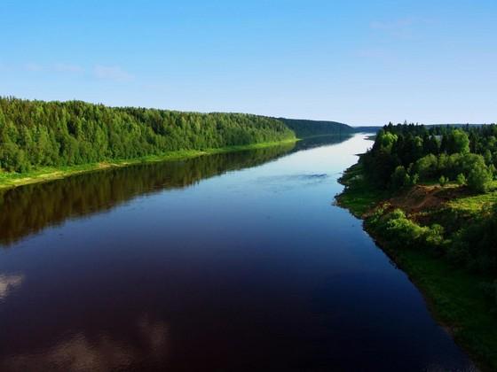
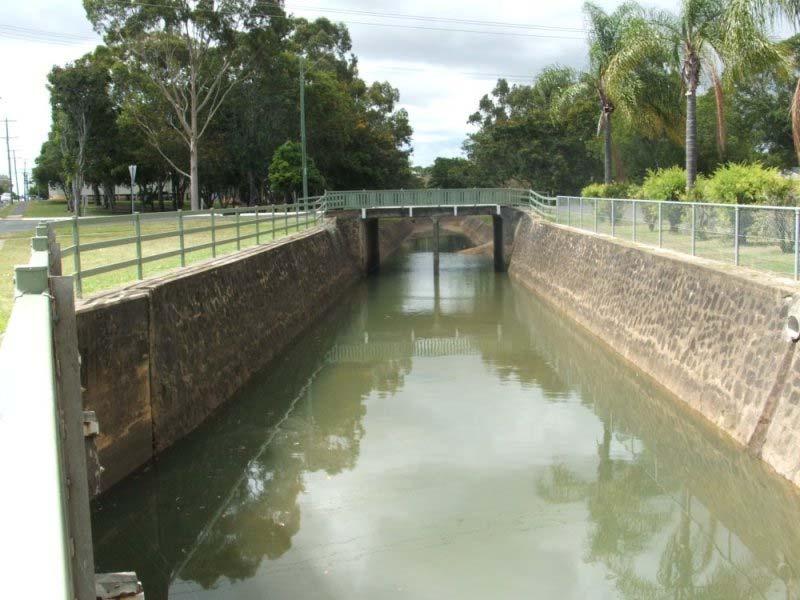
1 OPEN CHANNEL FLOW Open channel flow is a flow of liquid, basically water in a conduit with a free surface. The open channel flows are driven by gravity alone, and the pressure gradient at the atmospheric interface is negligible. Closed duct flows are full of fluid, have no free surface within, and are driven by a pressure gradient along the duct axis. That is a surface on which pressure is equal to local atmospheric pressure. Open channel flows are characterized by the presence of a liquid-gas interface called the free surface. Some are natural flows such as rivers, creeks and floods, some are human made systems such as fresh water aquaducts, irrigation, sewers and drainage ditches.
2

3 An open channel always has two sides and a bottom, where the flow satisfies the no-slip condition. Therefore even a straight channel has a three-dimensional velocity distribution. Some measurements of straight channel velocity contours are shown below. The profiles are quite complex, with maximum velocity typically occurring in the midplane about 0% below the surface.
4 COMPARISON OF OPEN CHANNEL FLOW AND PIPE FLOW OPEN CHANNEL FLOW Open channel flow must have a free surface. A free surface is subject to atmospheric pressure. Flow area is determined by the geometry of the channel plus the level of free surface, which is likely to change along the flow direction and with as well as time. The cross section may be of any from circular to irregular form of natural streams, which may change along the flow direction and as well as with time. The depth of flow, discharge and the slopes of channel bottom and of the free surface are interdependent. PIPE FLOW No free surface in pipe flow. No direct atmospheric pressure, hydraulic pressure only. Flow area is fixed by the pipe dimensions. The cross section of a pipe is usually circular. The cross section of a pipe is usually circular. No such dependence.
5 TYPES OF OPEN CHANNEL FLOWS The most common method of classifying open channel flow is by the rate of change of the free surface depth. The simplest and most widely analyzed case in uniform flow. Type of flow Steady flow Uniform flow Uniform steady flow Varied steady flow Varied unsteady flow Rapidly varying flow Gradually varying flow Description When discharge (Q) does not change with time. When depth of fluid does not change for a selected length or section of the channel. When discharge does not change with time and depth remains constant for a selected section. Cross section should remain unchanged, referred to as a prismatic channel. When depth changes but discharge remains the same. When both depth and discharge change along a channel length of interest. Depth change is rapid. Depth change is gradual.

6 . Rapidly varying flow. Gradually varying flow. Hydraulic jump 4. Weir and waterfall 5. Gradually varying 6. Hydraulic drop due to change in channel slope
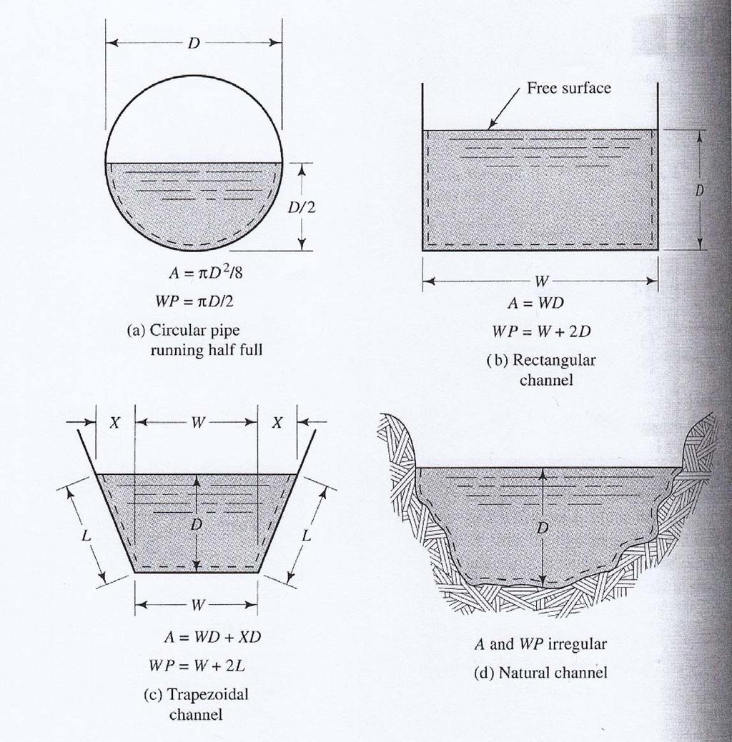
7 PARAMETER USED IN OPEN CHANNEL FLOW ANALYSIS Hydraulic radius, R of open channel flow R is a ratio of flow cross sectional area, A and wetted perimeter (WP) R = A WP R : Hydraulic radius A : Flow cross sectional area WP : Wetted perimeter
8
9 Reynolds number for open channel flow. Re = ρvr VR = μ υ Re < 500 laminar flow Re > 000 turbulent flow Reynolds number for pipe flow Re = ρvd VD = μ υ Re < 000 laminar flow Re > 4000 turbulent flow
10 Froude number, Fr The Froude number (Fr) is a dimensionless number defined as the ratio of channel velocity to the speed of propagation of a small disturbance wave in the channel. For a rectangular or very wide constant depth channel, Froude number can be defined as : Flow velocity Fr = = Surface wave speed where, V gy h V = Velocity g = gravity y h = Hydraulic depth y h = A T A = Area T = Top width of the channel Fr <.0 Sub-critical flow Fr =.0 or when V = gyh Critical flow Fr >.0 Super-critical flow A combination of both numbers is used to describe channel flow conditions.
11 THE CHEZY FORMULA Uniform flow can occur in long straight runs of constant slope and constant channel cross section. The water depth is constant at y = y n, and the velocity is constant at V = V 0. The slope be S = 0 tanθ, where θ is the angle the bottom makes with the horizontal, considered positive for downhill flow. From Bernoulli equation, the head loss becomes: h f = z z = S 0 L where L is the horizontal distance between section and. Head loss from Darcy-Weisbach is: h R f D D h h h L V = f Dh g A = 4 R h = 4 WP = Hydraulic diameter = Hydraulic radius 8g V0 = R h S f 0 For a given shape and bottom roughness, the quantity 8g C = f 8g f is constant and can be denoted by C.
12 Finally, the velocity V0 can be expressed as : V 0 8g = f R h S 0 = C ( R hs 0 ) Q = CA ( RhS 0 ) These are called Chezy formulas, first developed by the French engineer Antoine Chezy in conjuction with his experiments on the Saine River and the Courpalet Canal in 769. The quantity C, called the Chezy coefficient, varies about 60 ft ½ /s for small rough channels to 60 ft ½ /s for large smooth channels (0 m ½ /s to 90 m ½ /s in SI units).
13 EXAMPLE A straight rectangular channel is 6 ft wide and ft deep and laid on a slope of. The friction factor is 0.0. SOLUTION C = 8g f = = 08 ft A = 6 = 8 ft A 8 R h = = =.5 ft WP = tan S 0 s Q h = CA S 0 = ( R ) = ( 08)( 8) (.5 ( tan )) 450 ft /s For SI units, it can be used directly.
 flow inside the channel, it must have certain angle of inclination, or the channel s slope.")
14 Uniform steady flow and Manning s equation When discharge remain the same and depth does not change, then we have uniform steady flow. In this condition, the surface of water is parallel to the bed of the channel. To make sure water (liquid) flow inside the channel, it must have certain angle of inclination, or the channel s slope. The slope of the channel (S) can be expressed as :- An angle = degree As percent = % As fraction = 0.0 or in 00
15 Manning s equation is used to estimate the velocity of flow in a channel. The SI units form of Manning s equation:- V. 0 = R n S V = Velocity of flow in a channel (m/s) n = Channel surface roughness. Values developed through experimentation. R = Hydraulic radius (A/WP) in meter S = Slope of the channel The English units form of Manning s equation:- V.49 = R n S V = Velocity of flow in a channel (ft/s) R = Hydraulic radius (A/WP) in feet

16 Example of the n values:-
17 The flowrate of a channel could be determined by :- Q = AV. 0 = AR n S where Q is in m /s. For uniform flow, Q is referred to as normal discharge. The above equation can also be re-arranged such that :- AR = nq S The left hand side equation is based on channel geometry.

18 Example #0 Determine normal discharge for a 00 mm inside diameter common clay drainage tile running half-full if the slope drops m over 000m.. 0 Q = AR n S n = 0.0 πd A = = m 4 Wetted perimeter, WP = π D = 0.4 m A R = = = 0.05 m WP 0.4 S = Q = AR S = m /s n

19 Example #0 Calculate slope of channel if normal discharge is 50 ft /s. Channel is formed, unfinished concrete. English unit!!!.49 Q = AR S n A = ft WP = 9.66 ft A R = =.4 ft WP n = 0.07 S = Qn.49AR S = (Channel should drop.69 feet for every 000 feet length.
20 Example #0 Design a rectangular channel in formed, unfinished concrete with below mention specifications. Normal flowrate = 5.75 m /s S =.% Normal depth = half of the width of the channel. Since we have to design the channel, use this equation. AR = nq S B AR nq = = = 0.89 S ( 0.0) Y=B/ B A = BY = B = WP = B + Y = B A B R = = WP 4 B B B AR = 4 B =.76 m Y = 0.88 m = 0.89
21 Example #04 In a rectangular channel as mention in Example #0, the final width was set at m and the maximum discharge is m /s. Find the normal depth for this maximum discharge. AR = nq S AR nq 0.07 = = =.8657 S A = Y WP = + Y A Y R = = WP + Y ( 0.0) Y=B/ AR = Y + Y ( Y ) = Cannot solve directly. Use trial and error method. Can use MS Excel datasheet. From Excel, The normal depth must be.48 meter.

22 From MS Excel worksheet:
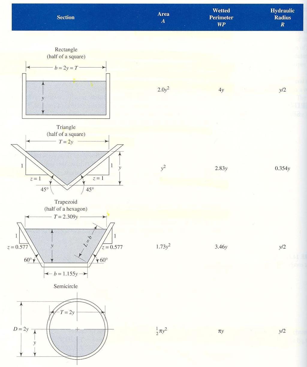
23 CONVEYANCE AND MOST EFFICIENT CHANNEL SHAPES. 0 Q = AR n S Other than the S term, all other terms are related to channel cross section and its features. These terms together are referred to as the Conveyance (K) of the channel. K. 0 = AR n Then, Q = K S R = A WP K is maximum when wetted perimeter (WP) is the least for a give area. This is also the most efficience cross section for conveying flow. For circular section, half full flow is the most efficient.
24
25 COMPOUND SECTIONS It is occurs when channel shape changes with flow depth. It is a typical idea in natural stream sections during flooding. At normal condition, water flows in the main channel. During floods, water spills over the flood plain. We need to know the flowrate, Q at various depths or vice-versa. So that we could design channels or determine channel safety for various flood magnitudes.

26 Example #05 Channel type: Natural channel with levees. Slope: Determine the normal discharge, Q for depth ft and 6 ft.
27
28 COMPOUND SECTION This is more realistic situation, where the channel roughness (value of n) may be different for floodplain than the main channel. In this case, we need to determine velocity for each sub-section, and then sum up the discharges for the sections. Example #06 Slope: 0.5% n for bank = 0.06 n for main channel = 0.0 Calculate discharge for depth of 8 feet?
29 A = 80 4 = 0 A = 50 8 = 400 A = 00 5 = 500 P = = 84 P = = 57 P = = 05 V i Q = Q =.49 Ai = ni Pi n i= A V i i S (.49)( 0.005) Q = 900 ft /s ( 0 / 84) 0 ( 400 / 57) 400 ( 500 /05)
30 ENERGY PRINCIPLES FOR OPEN CHANNEL FLOW Energy at particular point in the channel is potential energy and kinetic energy. Specific energy: V Q E = y + = y + g ga y = Depth of flow V = Velocity Q = Discharge A = Cross sectional flow area Total energy: V Q E = y + z + = y + z + g ga z = Height of the channel bottom from the datum
31 Example: Rectangular channel width = m Depth = m Q = 4.0 m/s Height above datum = m Determine the specific energy and total energy. Specific energy: m m m E = V y + g = + 4 ( )( 9.8)( ) =.0 m Datum Total energy: E = datum height + specific energy =.0 +. =. m
32 Specific energy diagram The specific energy can be plotted graphically as a function of depth of flow. V Q E = y + = y + g ga y = Static energy, E Q ga = Kinetic energy, E s (potential energy) k Relationship between y and static energy, E s
33 Relationship between y and kinetic energy, E k E k = Q ga For a rectangular channel; Substitute Q with specific discharge (discharge per unit width), Substitute area, A with, A = B y Q q = B Q E k = = q ga gy
34 EXAMPLE A rectangular channel, width is 4 m, flowrate is m /s and depth of flow is.5 m. Draw specific energy diagram Find critical and alternate depth? Q E = y + ga q E = y + gy Q q = = = m /s B 4

35 static E = y kinetic E total E.5 y Energy
36 Meaning from the graph:
37 . The diagram applies for a given cross section and discharge.. As the depth of flow increases, the static energy increases, and the kinetic energy decreases. The total energy curve approaches the static energy curve for high depths and the kinetic energy curve for small depths 4. The specific energy is minimum (Emin) for a particular depth this depth happens to be the critical depth Depth for which the Froude s number =.0. velocity = Vc. 5. Emin only energy value with a singular depth! 6. Depths less than the critical depths supercritical flow. Froude Number >.0. V > Vc. 7. Depths greater than the critical depths subcritical flow. Froude Number <.0. V < Vc. 8. For all other energy values there are two depth associated one greater than the critical depth and one less than the critical depth. 9. The two depths associated with the same energy values are referred to as Alternate depths 0. As discharge increases, the specific energy curves move to the upper right portion of the chart.
38
39 E = E = Q y + ga q y + gy There is a minimum value of E at a certain value of y called the critical depth. de dy q = 0 = gy It shows that E min occurs at y c y c q = g Q = b g The associated minimum energy is ; E min = E = ( y c ) y c The depth, y c corresponds to channel velocity equal to the shallow-water wave propagation speed, C 0. Fr = V gy ( gy ) y V y q = gyc = c c = c c
40 By comparison it follows that the critical channel velocity is: V c = = ( gyc ) C0 Fr = For For E < E min, no solution exists. E > E min, two solutions are possible: () Large depth with V < V c, called sub-critical. () Small depth with V > V c, called super-critical. In sub-critical flow, disturbances can propagate upstream because wave speed C 0 > V. In super-critical flow, waves are swept downstream: Upstream is a zone of silence, and a small obstruction in the flow will create a wedge-shape wave exactly analogous to the Mach waves. The angle of these waves must be: μ = sin C0 V = sin ( gy) V The wave angle and the depth can thus be used as a simple measurement of super-critical flow velocity.
41
42 Critical depth, y c y c q = g = 9.8 = 0.97 m Minimum specific energy, E min E y = ( 0.97).457 m min = c = Since given depth was.5 m > 0.97 m, the given depth is sub-critical and the other depth should be super-critical. Now, determining alternate depths (Energy at.5 m) E = q y + gy = =.57 m This energy value is the same for the other alternate (super-critical) depth, so;.57 = y y Determine value of y by trial and error method. (use Excel ok)

43 super-critical alternate depth, y = m
44
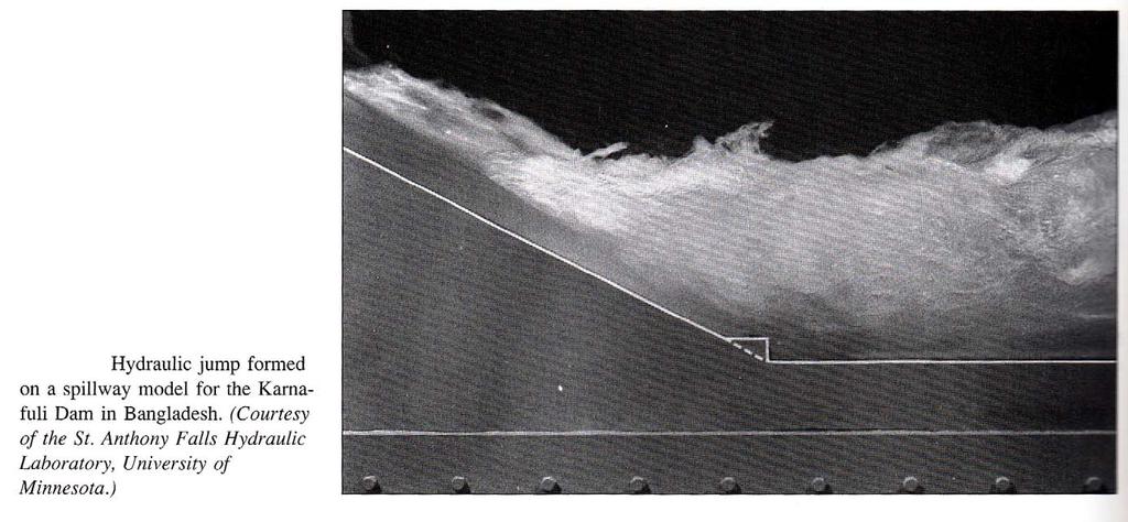
45 HYDRAULIC JUMP In open channel flow a supercritical flow can change quickly back to a subcritical flow by passing through a hydraulic jump The upstream flow is fast and shallow. The downstream flow is slow and deep. The hydraulic jump is quite thick, ranging in length from 4 to 6 time the downstream depth. It is very important that such jumps be located on specially designed aprons; otherwise the channel bottom will be badly scoured by the agitation. Jumps also mixed fluids very effectively and have application to sewage and water treatment designs.
46
47

48 EXAMPLE #0 Data:. Triangular channel with side slopes having ratio of :.5. Flowrate is 0.68 ft /s. Channel type clean, excavated earth Calculate:. Critical depth. Minimum specific energy. Plot specific energy curve 4. Determine energy for 0.45 ft and alternate depth 5. Velocity of flow and Froude number 6. Calculate require slope for given flow
49 SOLUTION FOR EXAMPLE #0 Used Excel. z =.5 Q = 0.68 ft /s n = 0.0 y = independence number Area, A = ( zy)( y) = zy Flow velocity, Q V = A Free surface width, T = zy Hydraulic depth, y h = A T

50 We cannot solve this question directly because the dimension of the triangular weir is not given. Trial and error method need to be applied. First step, create excel worksheet and calculate all the important parameter.
 Minimum specific energy, E min Minimum specific energy occur at critical depth. E min = 0.")
51 () Critical depth Critical depth occur at minimum energy, or at Froude number, Fr =.0 Find in the excel worksheet. Critical depth is 0.5 ft () Minimum specific energy, E min Minimum specific energy occur at critical depth. E min = ft
52 (c) Plot the graph y-axis is E (energy) and x-axis is depth (y) Specific energy.4. Depth (ft) Energy (ft)


53 (d) depth 0.45 ft, Energy = ft Alternate depth = ft (which has same specific energy)
54 (e) Velocity for y = ft, V =.4 ft/m, Fr =.5, super-critical flow for y = ft, V =.09 ft/m, Fr = 0.6, sub-critical flow (f) slope? Take y = 0.45 ft For triangle, Cross section area, A = zy ( ) y ( )= zy = Wetted perimeter, A = y + z =.65 Hydraulic radius, R = A WP = = 0.87 Flowrate, Q =.49 n AR So, slope, S = S Qn (.49)AR = 0.0 Or foot drop for every 00 feets.
55 EXAMPLE #0 (0.) Water at 0 C flows in a 0 cm wide rectangular channel at a depth of 0 cm and a flowrate of 80,000 cm /s. Estimate (a) the Froude number and (b) the Reynolds number. EXAMPLE #0 (0.8) An earthquake near the Kenai peninsula, Alaska, creates a single tidal wave called tsunami that propagates southward across the Pacific Ocean. If the average ocean depth is 4 km and seawater density is 05 kg/m, estimate the time of arrival of this tsunami in Hilo, Hawaii. EXAMPLE #04 (0.) A rectangular channel is m wide and contains water m deep. If the slope is 0.85 and the lining is corrugated metal, estimate the discharge for uniform flow.

56 EXAMPLE #05 ( ) The trapezoidal channel as shown below is made of brickwork and slopes at :500.. Determine the flowrate if the normal depth is 80 cm.. Determine the normal depth for which the flowrate will be 8 m /s.. Let the surface be clean earth, which erodes if V exceeds.5 m/s. What is the maximum depth to avoid erosion?

57 EXAMPLE #06 (0.84) Consider the flow under the sluice gate. If y =0 ft and all losses are neglected except the dissipation in the jump, calculate y and y and the percentage of dissipation, and sketch the flow to scale with the EGL included. The channel is horizontal and wide.
 Water 0cm deep is in uniform flow down a unfinished concrete slope when a hydraulic jump")
58 EXAMPLE #07 (0.89) Water 0cm deep is in uniform flow down a unfinished concrete slope when a hydraulic jump occurs. If the channel is very wide, estimate the water depth y downstream of the jump.
 Water in horizontal channel accelerates smoothly over a bump and then undergoes a hydraulic")
59 EXAMPLE #08 (0.9) Water in horizontal channel accelerates smoothly over a bump and then undergoes a hydraulic jump. If y = m and y = 40cm, estimate (a) V, (b) V, (c) y 4 and (d) the bump height, h.
 A 0 cm high bump in a wide horizontal water channel creates a hydraulic jump just upstream.")
60 EXAMPLE #09 (0.95) A 0 cm high bump in a wide horizontal water channel creates a hydraulic jump just upstream. Neglecting losses except in the jump, for case y = 0cm, estimate (a) V 4, (b) y 4, (c) V and (d) y.

61 EXAMPLE #0 (C0.6) Figure shows a horizontal flow of water through a sluice gate, a hydraulic jump, and over 6 ft sharp crested weir. Channel, gate, jump and weir are all 8 ft wide unfinished concrete. Determine (a) the flow rate, (b) the normal depth, (c) y, (d) y and (e) y 4.
Closed duct flows are full of fluid, have no free surface within, and are driven by a pressure gradient along the duct axis.
 OPEN CHANNEL FLOW Open channel flow is a flow of liquid, basically water in a conduit with a free surface. The open channel flows are driven by gravity alone, and the pressure gradient at the atmospheric
P10.5 Water flows down a rectangular channel that is 4 ft wide and 3 ft deep. The flow rate is 15,000 gal/min. Estimate the Froude number of the flow.
 P10.5 Water flows down a rectangular channel that is 4 ft wide and ft deep. The flow rate is 15,000 gal/min. Estimate the Froude number of the flow. Solution: Convert the flow rate from 15,000 gal/min
Presented by: Civil Engineering Academy
 Presented by: Civil Engineering Academy Open-Channel Flow Uniform Flow (See CERM Ch. 19) Characterized by constant depth volume, and cross section. It can be steady or unsteady Non-uniform Flow *Not on
We will assume straight channels with simple geometries (prismatic channels) and steady state flow (in time).
 and steady state flow (in time).") 56 Review Drag & Lift Laminar vs Turbulent Boundary Layer Turbulent boundary layers stay attached to bodies longer Narrower wake! Lower pressure drag! 8. Open-Channel Flow Pipe/duct flow closed, full,
56 Review Drag & Lift Laminar vs Turbulent Boundary Layer Turbulent boundary layers stay attached to bodies longer Narrower wake! Lower pressure drag! 8. Open-Channel Flow Pipe/duct flow closed, full,
Hydraulics Part: Open Channel Flow
 Hydraulics Part: Open Channel Flow Tutorial solutions -by Dr. K.N. Dulal Uniform flow 1. Show that discharge through a channel with steady flow is given by where A 1 and A 2 are the sectional areas of
Open Channel Flow Part 2. Ch 10 Young, notes, handouts
 Open Channel Flow Part 2 Ch 10 Young, notes, handouts Uniform Channel Flow Many situations have a good approximation d(v,y,q)/dx=0 Uniform flow Look at extended Bernoulli equation Friction slope exactly
STEADY UNIFORM FLOW IN OPEN CHANNEL
 11/4/018 School of Environmental Engineering STEY UNIFORM FLOW IN OEN CHNNEL ZULKRNIN BIN HSSN COURSE OUTCOMES CO1: ble to analyze and design the steady flow in pipeline (O1) CO: ble to analyze and design
LECTURE 9: Open channel flow: Uniform flow, best hydraulic sections, energy principles, Froude number
 LECTURE 9: Open channel flow: Uniform flow, best hydraulic sections, energy principles, Froude number Assist. Prof. Neslihan SEMERCİ Marmara University Department of Environmental Engineering Open channel
OPEN CHANNEL FLOW. One-dimensional - neglect vertical and lateral variations in velocity. In other words, Q v = (1) A. Figure 1. One-dimensional Flow
 A. Figure 1. One-dimensional Flow") OPEN CHANNEL FLOW Page 1 OPEN CHANNEL FLOW Open Channel Flow (OCF) is flow with one boundary exposed to atmospheric pressure. The flow is not pressurized and occurs because of gravity. Flow Classification
OPEN CHANNEL FLOW Page 1 OPEN CHANNEL FLOW Open Channel Flow (OCF) is flow with one boundary exposed to atmospheric pressure. The flow is not pressurized and occurs because of gravity. Flow Classification
Open Channel Flow I - The Manning Equation and Uniform Flow COURSE CONTENT
 Open Channel Flow I - The Manning Equation and Uniform Flow Harlan H. Bengtson, PhD, P.E. COURSE CONTENT 1. Introduction Flow of a liquid may take place either as open channel flow or pressure flow. Pressure
Uniform Flow in Open Channels
 1 UNIT 2 Uniform Flow in Open Channels Lecture-01 Introduction & Definition Open-channel flow, a branch of hydraulics, is a type of liquid flow within a conduit with a free surface, known as a channel.
VARIED FLOW IN OPEN CHANNELS
 Chapter 15 Open Channels vs. Closed Conduits VARIED FLOW IN OPEN CHANNELS Fluid Mechanics, Spring Term 2011 In a closed conduit there can be a pressure gradient that drives the flow. An open channel has
DEPARTMENT OF CIVIL AND ENVIRONMENTAL ENGINEERING Urban Drainage: Hydraulics. Solutions to problem sheet 2: Flows in open channels
 DEPRTMENT OF CIVIL ND ENVIRONMENTL ENGINEERING Urban Drainage: Hydraulics Solutions to problem sheet 2: Flows in open channels 1. rectangular channel of 1 m width carries water at a rate 0.1 m 3 /s. Plot
NPTEL Quiz Hydraulics
 Introduction NPTEL Quiz Hydraulics 1. An ideal fluid is a. One which obeys Newton s law of viscosity b. Frictionless and incompressible c. Very viscous d. Frictionless and compressible 2. The unit of kinematic
Water Flow in Open Channels
 The Islamic Universit of Gaza Facult of Engineering Civil Engineering Department Hdraulics - ECIV 33 Chapter 6 Water Flow in Open Channels Introduction An open channel is a duct in which the liquid flows
UNIFORM FLOW CRITICAL FLOW GRADUALLY VARIED FLOW
 UNIFORM FLOW CRITICAL FLOW GRADUALLY VARIED FLOW Derivation of uniform flow equation Dimensional analysis Computation of normal depth UNIFORM FLOW 1. Uniform flow is the flow condition obtained from a
Fluid Mechanics Prof. S.K. Som Department of Mechanical Engineering Indian Institute of Technology, Kharagpur
 Fluid Mechanics Prof. S.K. Som Department of Mechanical Engineering Indian Institute of Technology, Kharagpur Lecture - 42 Flows with a Free Surface Part II Good morning. I welcome you to this session
Lecture Note for Open Channel Hydraulics
 Chapter -one Introduction to Open Channel Hydraulics 1.1 Definitions Simply stated, Open channel flow is a flow of liquid in a conduit with free space. Open channel flow is particularly applied to understand
CEE 3310 Open Channel Flow, Nov. 26,
 CEE 3310 Open Channel Flow, Nov. 6, 018 175 8.10 Review Open Channel Flow Gravity friction balance. y Uniform Flow x = 0 z = S 0L = h f y Rapidly Varied Flow x 1 y Gradually Varied Flow x 1 In general
Open Channel Hydraulics I - Uniform Flow
 PDHonline Course H138 (2 PDH) Open Channel Hydraulics I - Uniform Flow Instructor: Harlan H. Bengtson, Ph.D., PE 2012 PDH Online PDH Center 5272 Meadow Estates Drive Fairfax, VA 22030-6658 Phone & Fax:
Flow in Open Channel Flow Conditions
 Civil Engineering Hydraulics Flow The graduate with a Science degree asks, "Why does it work?" The graduate with an Engineering degree asks, "How does it work?" The graduate with an Accounting degree asks,
Lecture 10: River Channels
 GEOG415 Lecture 10: River Channels 10-1 Importance of channel characteristics Prediction of flow was the sole purpose of hydrology, and still is a very important aspect of hydrology. - Water balance gives
1.060 Engineering Mechanics II Spring Problem Set 8
 1.060 Engineering Mechanics II Spring 2006 Due on Monday, May 1st Problem Set 8 Important note: Please start a new sheet of paper for each problem in the problem set. Write the names of the group members
Hydraulics for Urban Storm Drainage
 Urban Hydraulics Hydraulics for Urban Storm Drainage Learning objectives: understanding of basic concepts of fluid flow and how to analyze conduit flows, free surface flows. to analyze, hydrostatic pressure
Hydromechanics: Course Summary
 Hydromechanics: Course Summary Hydromechanics VVR090 Material Included; French: Chapters to 9 and 4 + Sample problems Vennard & Street: Chapters 8 + 3, and (part of it) Roberson & Crowe: Chapter Collection
CE 6403 APPLIED HYDRAULIC ENGINEERING UNIT - II GRADUALLY VARIED FLOW
 CE 6403 APPLIED HYDRAULIC ENGINEERING UNIT - II GRADUALLY VARIED FLOW Dynamic equations of gradually varied and spatially varied flows - Water surface flow profile classifications: Hydraulic Slope, Hydraulic
Open-channel hydraulics
 Open-channel hydraulics STEADY FLOW IN OPEN CHANNELS constant discharge, other geometric and flow characteristics depended only on position Uniform flow Non-uniform flow S; y; v const. i i 0 i E y 1 y
Q = α n AR2/3 h S1/2 0. bd 2d + b d if b d. 0 = ft1/3 /s
 CEE 330 Open Channel Flow, Nov., 00 7 8.8 Review Open Channel Flow Gravity friction balance. In general we take an energy equation approach. y Uniform Flow x = 0 z = S 0L = h f where we could find h f
Hydraulics Prof. Dr. Arup Kumar Sarma Department of Civil Engineering Indian Institute of Technology, Guwahati
 Hydraulics Prof. Dr. Arup Kumar Sarma Department of Civil Engineering Indian Institute of Technology, Guwahati Module No. # 04 Gradually Varied Flow Lecture No. # 07 Rapidly Varied Flow: Hydraulic Jump
CIE4491 Lecture. Hydraulic design
 CIE4491 Lecture. Hydraulic design Marie-claire ten Veldhuis 19-9-013 Delft University of Technology Challenge the future Hydraulic design of urban stormwater systems Focus on sewer pipes Pressurized and
P = 2Rθ. The previous Manning formulas are used to predict V o and Q for uniform flow when the above expressions are substituted for A, P, and R h.
 Uniform Flow in a Partly Full, Circular Pipe Fig. 10.6 shows a partly full, circular pipe with uniform flow. Since frictional resistance increases with wetted perimeter, but volume flow rate increases
1. Open Channel Hydraulics
 Open Channel Flow. Open Channel Hydraulics.... Definition and differences between pipe flow and open channel flow.... Types of flow.... Properties of open channels...4.4 Fundamental equations... 5.4. The
Chapter 4: Non uniform flow in open channels
 Chapter 4: Non uniform flow in open channels Learning outcomes By the end of this lesson, students should be able to: Relate the concept of specific energy and momentum equations in the effect of change
28.2 Classification of Jumps
 28.2 Classification of Jumps As mentioned earlier, the supercritical flow Froude number influences the characteristics of the hydraulic jump. Bradley and Peterka, after extensive experimental investigations,
Basic Hydraulics. Rabi H. Mohtar ABE 325
 Basic Hydraulics Rabi H. Mohtar ABE 35 The river continues on its way to the sea, broken the wheel of the mill or not. Khalil Gibran The forces on moving body of fluid mass are:. Inertial due to mass (ρ
Gradually Varied Flow I+II. Hydromechanics VVR090
 Gradually Varied Flow I+II Hydromechanics VVR090 Gradually Varied Flow Depth of flow varies with longitudinal distance. Occurs upstream and downstream control sections. Governing equation: dy dx So Sf
Manning Equation - Open Channel Flow using Excel. Harlan H. Bengtson, PhD, P.E. COURSE CONTENT
 Manning Equation - Open Channel Flow using Excel Harlan H. Bengtson, PhD, P.E. COURSE CONTENT 1. Introduction The Manning equation is a widely used empirical equation for uniform open channel flow of water.
FE Fluids Review March 23, 2012 Steve Burian (Civil & Environmental Engineering)
") Topic: Fluid Properties 1. If 6 m 3 of oil weighs 47 kn, calculate its specific weight, density, and specific gravity. 2. 10.0 L of an incompressible liquid exert a force of 20 N at the earth s surface.
Topic: Fluid Properties 1. If 6 m 3 of oil weighs 47 kn, calculate its specific weight, density, and specific gravity. 2. 10.0 L of an incompressible liquid exert a force of 20 N at the earth s surface.
UNIT I FLUID PROPERTIES AND STATICS
 SIDDHARTH GROUP OF INSTITUTIONS :: PUTTUR Siddharth Nagar, Narayanavanam Road 517583 QUESTION BANK (DESCRIPTIVE) Subject with Code : Fluid Mechanics (16CE106) Year & Sem: II-B.Tech & I-Sem Course & Branch:
Open Channel Flow - General. Hydromechanics VVR090
 Open Channel Flow - General Hydromechanics VVR090 ppt by Magnus Larson; revised by Rolf L Jan 2014, Feb 2015 SYNOPSIS 1. Introduction and Applications 2. The History of Open Channel Flow 3. Flow Classification
Open Channel Flow - General. Open Channel Flow
 Open Channel Flow - General Hydromechanics VVR090 Open Channel Flow Open channel: a conduit for flow which has a free surface Free surface: interface between two fluids of different density Characteristics
Open Channel Hydraulics
 30 Open Channel Hydraulics Aldo Giorgini (deceased) Donald D. Gray West Virginia University 30. Definitions and Principles Classification of Flows Flow Regimes 30. Balance and Conservation Principles Conservation
Chapter (3) Water Flow in Pipes
 Water Flow in Pipes") Chapter (3) Water Flow in Pipes Water Flow in Pipes Bernoulli Equation Recall fluid mechanics course, the Bernoulli equation is: P 1 ρg + v 1 g + z 1 = P ρg + v g + z h P + h T + h L Here, we want to study
Chapter (3) Water Flow in Pipes Water Flow in Pipes Bernoulli Equation Recall fluid mechanics course, the Bernoulli equation is: P 1 ρg + v 1 g + z 1 = P ρg + v g + z h P + h T + h L Here, we want to study
OPEN CHANNEL FLOW. Computer Applications. Numerical Methods and. Roland Jeppson. CRC Press UNIVERSITATSB'BUOTHEK TECHNISCHE. INFORMATlONSBiBUOTHEK
 OPEN CHANNEL FLOW Numerical Methods and Computer Applications Roland Jeppson TECHNISCHE INFORMATlONSBiBUOTHEK UNIVERSITATSB'BUOTHEK HANNOVER Si. i. CRC Press Taylor &.Francis Group Boca Raton London New
R09. d water surface. Prove that the depth of pressure is equal to p +.
 Code No:A109210105 R09 SET-1 B.Tech II Year - I Semester Examinations, December 2011 FLUID MECHANICS (CIVIL ENGINEERING) Time: 3 hours Max. Marks: 75 Answer any five questions All questions carry equal
Fluvial Dynamics. M. I. Bursik ublearns.buffalo.edu October 26, Home Page. Title Page. Contents. Page 1 of 18. Go Back. Full Screen. Close.
 Page 1 of 18 Fluvial Dynamics M. I. Bursik ublearns.buffalo.edu October 26, 2008 1. Fluvial Dynamics We want to understand a little of the basic physics of water flow and particle transport, as so much
3.2 CRITICAL DEPTH IN NONRECTANGULAR CHANNELS AND OCCUR- RENCE OF CRITICAL DEPTH
 3.2 CRITICAL DEPTH IN NONRECTANGULAR CHANNELS AND OCCUR- RENCE OF CRITICAL DEPTH Critical Depth in Non-Rectangular Channels Consider an irregular channel: da w dd dd d Specific energy is defined as: E
FLOW IN CONDUITS. Shear stress distribution across a pipe section. Chapter 10
 Chapter 10 Shear stress distribution across a pipe section FLOW IN CONDUITS For steady, uniform flow, the momentum balance in s for the fluid cylinder yields Fluid Mechanics, Spring Term 2010 Velocity
Pressure Head: Pressure head is the height of a column of water that would exert a unit pressure equal to the pressure of the water.
 Design Manual Chapter - Stormwater D - Storm Sewer Design D- Storm Sewer Sizing A. Introduction The purpose of this section is to outline the basic hydraulic principles in order to determine the storm
y 2 = 1 + y 1 This is known as the broad-crested weir which is characterized by:
 CEE 10 Open Channel Flow, Dec. 1, 010 18 8.16 Review Flow through a contraction Critical and choked flows The hydraulic jump conservation of linear momentum y = 1 + y 1 1 + 8Fr 1 8.17 Rapidly Varied Flows
EFFECT OF BAFFLE BLOCKS ON THE PERFORMANCE OF RADIAL HYDRAULIC JUMP
 Fourth International Water Technology Conference IWTC 99, Alexandria, Egypt 255 EFFECT OF BAFFLE BLOCKS ON THE PERFORMANCE OF RADIAL HYDRAULIC JUMP O. S. Rageh Irrigation & Hydraulics Dept., Faculty of
New Website: M P E il Add. Mr. Peterson s Address:
 Brad Peterson, P.E. New Website: http://njut009fall.weebly.com M P E il Add Mr. Peterson s Email Address: bradpeterson@engineer.com If 6 m 3 of oil weighs 47 kn calculate its If 6 m 3 of oil weighs 47
Department of Hydro Sciences, Institute for Urban Water Management. Urban Water
 Department of Hydro Sciences, Institute for Urban Water Management Urban Water 1 Global water aspects Introduction to urban water management 3 Basics for systems description 4 Water transport 5 Matter
INSTITUTE OF AERONAUTICAL ENGINEERING Dundigal, Hyderabad AERONAUTICAL ENGINEERING QUESTION BANK : AERONAUTICAL ENGINEERING.
 Course Name Course Code Class Branch INSTITUTE OF AERONAUTICAL ENGINEERING Dundigal, Hyderabad - 00 0 AERONAUTICAL ENGINEERING : Mechanics of Fluids : A00 : II-I- B. Tech Year : 0 0 Course Coordinator
Lesson 6 Review of fundamentals: Fluid flow
 Lesson 6 Review of fundamentals: Fluid flow The specific objective of this lesson is to conduct a brief review of the fundamentals of fluid flow and present: A general equation for conservation of mass
53:071 Principles of Hydraulics Laboratory Experiment #3 ANALYSIS OF OPEN-CHANNEL FLOW TRANSITIONS USING THE SPECIFIC ENERGY DIAGRAM
 53:071 Principles of Hydraulics Laboratory Experiment #3 ANALYSIS OF OPEN-CHANNEL FLOW TRANSITIONS USING THE SPECIFIC ENERGY DIAGRAM Principle Adaptation of the Bernoulli equation to open-channel flows
Dr. Muhammad Ali Shamim ; Internal 652
 Dr. Muhammad Ali Shamim ali.shamim@uettaxila.edu.pk 051-904765; Internal 65 Channel Tranistions A channel transition is defined as change in channel cross section e.g. change in channel width and/or channel
1 Branch: CIVIL ENGINEERING Sub: HYDRAULICS AND HYDRAULIC MACHINERY Date: 11/03/2017
 G.PULLAIAH COLLEGE OF ENGINEERING & TECHNOLOGY (AT) II B.Tech Objective Paper I MID EXAM 1 Branch: CIVIL ENGINEERING Sub: HYDRAULICS AND HYDRAULIC MACHINERY Date: 11/03/2017 Time: 20 min Max.Marks:10 Roll
Uniform Channel Flow Basic Concepts Hydromechanics VVR090
 Uniform Channel Flow Basic Concepts Hydromechanics VVR090 ppt by Magnus Larson; revised by Rolf L Feb 2014 SYNOPSIS 1. Definition of Uniform Flow 2. Momentum Equation for Uniform Flow 3. Resistance equations
presented by Umut Türker Open Channel Flow
 presented by Umut Türker Open Channel Flow What is open channel flow? Open channel flow is a flow which has a free surface and flows due to the gravitational effect What is open channel flow? Open channel
Geology 550 Spring 2005 LAB 3: HYDRAULICS OF PRAIRIE CREEK
 Geology 550 Spring 2005 LAB 3: HYDRAULICS OF PRAIRIE CREEK Objectives: 1. To examine the distribution of velocity in a stream channel 2. To characterize the state of flow using dimensionless variables
MODELING FLUID FLOW IN OPEN CHANNEL WITH HORSESHOE CROSS SECTION
 July. 2. Vol. 7. No. 2 MODELING FLUID FLOW IN OPEN CHANNEL WITH HORSESHOE CROSS SECTION 1 J. JOMBA, 2 D.M.THEURI, 2 E. MWENDA, 2 C. CHOMBA ABSTRACT Flow in a closed conduit is regarded as open channel
Advanced Hydraulics Prof. Dr. Suresh A. Kartha Department of Civil Engineering Indian Institute of Technology, Guwahati
 Advanced Hydraulics Prof. Dr. Suresh A. Kartha Department of Civil Engineering Indian Institute of Technology, Guwahati Module - 2 Uniform Flow Lecture - 1 Introduction to Uniform Flow Good morning everyone,
5. ROADSIDE AND MEDIAN CHANNELS
 5. ROADSIDE AND MEDIAN CHANNELS Roadside and median channels are open-channel systems which collect and convey stormwater from the pavement surface, roadside, and median areas. These channels may outlet
Chapter 3 Bernoulli Equation
 1 Bernoulli Equation 3.1 Flow Patterns: Streamlines, Pathlines, Streaklines 1) A streamline, is a line that is everywhere tangent to the velocity vector at a given instant. Examples of streamlines around
Guo, James C.Y. (1999). "Critical Flow Section in a Collector Channel," ASCE J. of Hydraulic Engineering, Vol 125, No. 4, April.
. Critical Flow Section in a Collector Channel, ASCE J. of Hydraulic Engineering, Vol 125, No. 4, April.") Guo, James C.Y. (1999). "Critical Flow Section in a Collector Channel," ASCE J. of Hydraulic Engineering, Vol 15, No. 4, April. CRITICAL FLOW SECTION IN A COLLECTOR CHANNEL By James C.Y. Guo, PhD, P.E.
Guo, James C.Y. (1999). "Critical Flow Section in a Collector Channel," ASCE J. of Hydraulic Engineering, Vol 15, No. 4, April. CRITICAL FLOW SECTION IN A COLLECTOR CHANNEL By James C.Y. Guo, PhD, P.E.
SOE2156: Fluids Lecture 7
 Weirs and SOE2156: Fluids Lecture 7 Vee Vee Last lecture { assumed the channel was uniform (constant depth, shape, slope etc.) { steady uniform Found that : location of free surface to be determined 2
2.The lines that are tangent to the velocity vectors throughout the flow field are called steady flow lines. True or False A. True B.
 CHAPTER 03 1. Write Newton's second law of motion. YOUR ANSWER: F = ma 2.The lines that are tangent to the velocity vectors throughout the flow field are called steady flow lines. True or False 3.Streamwise
Beaver Creek Corridor Design and Analysis. By: Alex Previte
 Beaver Creek Corridor Design and Analysis By: Alex Previte Overview Introduction Key concepts Model Development Design Accuracy Conclusion Refresh v = Beaver Creek Site = Wittenberg Introduction Low head
Advanced Hydraulics Prof. Dr. Suresh A. Kartha Department of Civil Engineering Indian Institute of Technology, Guwahati
 Advanced Hydraulics Prof. Dr. Suresh A. Kartha Department of Civil Engineering Indian Institute of Technology, Guwahati Module - 5 Channel Transitions Lecture - 1 Channel Transitions Part 1 Welcome back
STEADY FLOW THROUGH PIPES DARCY WEISBACH EQUATION FOR FLOW IN PIPES. HAZEN WILLIAM S FORMULA, LOSSES IN PIPELINES, HYDRAULIC GRADE LINES AND ENERGY
 STEADY FLOW THROUGH PIPES DARCY WEISBACH EQUATION FOR FLOW IN PIPES. HAZEN WILLIAM S FORMULA, LOSSES IN PIPELINES, HYDRAULIC GRADE LINES AND ENERGY LINES 1 SIGNIFICANCE OF CONDUITS In considering the convenience
Properties and Definitions Useful constants, properties, and conversions
 Properties and Definitions Useful constants, properties, and conversions gc = 32.2 ft/sec 2 [lbm-ft/lbf-sec 2 ] ρwater = 1.96 slugs/ft 3 γwater = 62.4 lb/ft 3 1 ft 3 /sec = 449 gpm 1 mgd = 1.547 ft 3 /sec
conservation of linear momentum 1+8Fr = 1+ Sufficiently short that energy loss due to channel friction is negligible h L = 0 Bernoulli s equation.
 174 Review Flow through a contraction Critical and choked flows The hydraulic jump conservation of linear momentum y y 1 = 1+ 1+8Fr 1 8.1 Rapidly Varied Flows Weirs 8.1.1 Broad-Crested Weir Consider the
Chapter 6 The Impulse-Momentum Principle
 Chapter 6 The Impulse-Momentum Principle 6. The Linear Impulse-Momentum Equation 6. Pipe Flow Applications 6.3 Open Channel Flow Applications 6.4 The Angular Impulse-Momentum Principle Objectives: - Develop
Bernoulli and Pipe Flow
 Civil Engineering Hydraulics Mechanics of Fluids Head Loss Calculations Bernoulli and The Bernoulli equation that we worked with was a bit simplistic in the way it looked at a fluid system All real systems
Uniform Channel Flow Basic Concepts. Definition of Uniform Flow
 Uniform Channel Flow Basic Concepts Hydromechanics VVR090 Uniform occurs when: Definition of Uniform Flow 1. The depth, flow area, and velocity at every cross section is constant 2. The energy grade line,
Chapter 3.8: Energy Dissipators. By Dr. Nuray Denli Tokyay
 Chapter 3.8: Energy Dissipators By Dr. Nuray Denli Tokyay 3.1 Introduction A stilling basin is a short length of paved channel placed at the foot of a spillway or any other source of supercritical flow
Visualization of flow pattern over or around immersed objects in open channel flow.
 EXPERIMENT SEVEN: FLOW VISUALIZATION AND ANALYSIS I OBJECTIVE OF THE EXPERIMENT: Visualization of flow pattern over or around immersed objects in open channel flow. II THEORY AND EQUATION: Open channel:
ch-01.qxd 8/4/04 2:33 PM Page 1 Part 1 Basic Principles of Open Channel Flows
 ch-01.qxd 8/4/04 2:33 PM Page 1 Part 1 Basic Principles of Open Channel Flows ch-01.qxd 8/4/04 2:33 PM Page 3 Introduction 1 Summary The introduction chapter reviews briefly the basic fluid properties
FLUID MECHANICS PROF. DR. METİN GÜNER COMPILER
 FLUID MECHANICS PROF. DR. METİN GÜNER COMPILER ANKARA UNIVERSITY FACULTY OF AGRICULTURE DEPARTMENT OF AGRICULTURAL MACHINERY AND TECHNOLOGIES ENGINEERING 1 5. FLOW IN PIPES Liquid or gas flow through pipes
Hydraulics. B.E. (Civil), Year/Part: II/II. Tutorial solutions: Pipe flow. Tutorial 1
, Year/Part: II/II. Tutorial solutions: Pipe flow. Tutorial 1") Hydraulics B.E. (Civil), Year/Part: II/II Tutorial solutions: Pipe flow Tutorial 1 -by Dr. K.N. Dulal Laminar flow 1. A pipe 200mm in diameter and 20km long conveys oil of density 900 kg/m 3 and viscosity
Hydraulics B.E. (Civil), Year/Part: II/II Tutorial solutions: Pipe flow Tutorial 1 -by Dr. K.N. Dulal Laminar flow 1. A pipe 200mm in diameter and 20km long conveys oil of density 900 kg/m 3 and viscosity
The Impulse-Momentum Principle
 Chapter 6 /60 The Impulse-Momentum Principle F F Chapter 6 The Impulse-Momentum Principle /60 Contents 6.0 Introduction 6. The Linear Impulse-Momentum Equation 6. Pipe Flow Applications 6.3 Open Channel
Experiment- To determine the coefficient of impact for vanes. Experiment To determine the coefficient of discharge of an orifice meter.
 SUBJECT: FLUID MECHANICS VIVA QUESTIONS (M.E 4 th SEM) Experiment- To determine the coefficient of impact for vanes. Q1. Explain impulse momentum principal. Ans1. Momentum equation is based on Newton s
Experiment 7 Energy Loss in a Hydraulic Jump
 Experiment 7 Energ Loss in a Hdraulic Jump n Purpose: The purpose of this experiment is to examine the transition from supercritical (rapid) flow to subcritical (slow) flow in an open channel and to analze
Hydraulics and hydrology
 Hydraulics and hydrology - project exercises - Class 4 and 5 Pipe flow Discharge (Q) (called also as the volume flow rate) is the volume of fluid that passes through an area per unit time. The discharge
Review of pipe flow: Friction & Minor Losses
 ENVE 204 Lecture -1 Review of pipe flow: Friction & Minor Losses Assist. Prof. Neslihan SEMERCİ Marmara University Department of Environmental Engineering Important Definitions Pressure Pipe Flow: Refers
Lab 7: Nonuniform Flow and Open Channel Transitions
 CE 3620: Water Resources Engineering Spring 2015 Lab 7: Nonuniform Flow and Open Channel Transitions BACKGROUND An open channel transition may be defined as a change either in the direction, slope, or
Effect of Roughness on Discharge
 Effect of Roughness on Discharge T.W. Lau, and N.R. Afshar Abstract These Water resource projects and hydraulic engineering works have been developing rapidly throughout the world, thus prediction of water
Chapter 6. Losses due to Fluid Friction
 Chapter 6 Losses due to Fluid Friction 1 Objectives ä To measure the pressure drop in the straight section of smooth, rough, and packed pipes as a function of flow rate. ä To correlate this in terms of
The University cannot take responsibility for any misprints or errors in the presented formulas. Please use them carefully and wisely.
 Aide Mémoire Suject: Useful formulas for flow in rivers and channels The University cannot take responsiility for any misprints or errors in the presented formulas. Please use them carefully and wisely.
Reynolds, an engineering professor in early 1880 demonstrated two different types of flow through an experiment:
 7 STEADY FLOW IN PIPES 7.1 Reynolds Number Reynolds, an engineering professor in early 1880 demonstrated two different types of flow through an experiment: Laminar flow Turbulent flow Reynolds apparatus
GEOL 652. Poudre River Fieldtrip
 GEOL 652. Poudre River Fieldtrip One of the more difficult variables to measure and/or estimate when studying flow in natural channels is that of roughness. Roughness, usually approximated with Manning
Determining Coefficient of Discharge to Compare Coefficients of Resistance for Different Coarse Aggregate Beds
 2015 IJSRSET Volume 1 Issue 4 Print ISSN : 2395-1990 Online ISSN : 2394-4099 Themed Section: Engineering and Technology Determining Coefficient of Discharge to Compare Coefficients of Resistance for Different
CIVL4120/7020 Advanced open channel hydraulics and design - Tutorial (1) Unsteady open channel flows
 Unsteady open channel flows") School of Civil Engineering at the University of Queensland CIVL4120/7020 Advanced open channel hydraulics and design - Tutorial (1) Unsteady open channel flows Attendance to tutorials is very strongly
School of Civil Engineering at the University of Queensland CIVL4120/7020 Advanced open channel hydraulics and design - Tutorial (1) Unsteady open channel flows Attendance to tutorials is very strongly
Open Channel Hydraulics III - Sharpcrested
 PDHonline Course H140 (2 PDH) Open Channel Hydraulics III - Sharpcrested Weirs Instructor: Harlan H. Bengtson, Ph.D., PE 2012 PDH Online PDH Center 5272 Meadow Estates Drive Fairfax, VA 22030-6658 Phone
Lesson 37 Transmission Of Air In Air Conditioning Ducts
 Lesson 37 Transmission Of Air In Air Conditioning Ducts Version 1 ME, IIT Kharagpur 1 The specific objectives of this chapter are to: 1. Describe an Air Handling Unit (AHU) and its functions (Section 37.1).
Fluid Mechanics Prof. T.I. Eldho Department of Civil Engineering Indian Institute of Technology, Bombay. Lecture - 17 Laminar and Turbulent flows
 Fluid Mechanics Prof. T.I. Eldho Department of Civil Engineering Indian Institute of Technology, Bombay Lecture - 17 Laminar and Turbulent flows Welcome back to the video course on fluid mechanics. In
S.E. (Mech.) (First Sem.) EXAMINATION, (Common to Mech/Sandwich) FLUID MECHANICS (2008 PATTERN) Time : Three Hours Maximum Marks : 100
 (First Sem.) EXAMINATION, (Common to Mech/Sandwich) FLUID MECHANICS (2008 PATTERN) Time : Three Hours Maximum Marks : 100") Total No. of Questions 12] [Total No. of Printed Pages 8 Seat No. [4262]-113 S.E. (Mech.) (First Sem.) EXAMINATION, 2012 (Common to Mech/Sandwich) FLUID MECHANICS (2008 PATTERN) Time : Three Hours Maximum
Total No. of Questions 12] [Total No. of Printed Pages 8 Seat No. [4262]-113 S.E. (Mech.) (First Sem.) EXAMINATION, 2012 (Common to Mech/Sandwich) FLUID MECHANICS (2008 PATTERN) Time : Three Hours Maximum
CEE 3310 Open Channel Flow,, Nov. 18,
 CEE 3310 Open Channel Flow,, Nov. 18, 2016 165 8.1 Review Drag & Lit Laminar vs Turbulent Boundary Layer Turbulent boundary layers stay attached to bodies longer Narrower wake! Lower pressure drag! C D
Advanced Hydraulics Prof. Dr. Suresh A Kartha Department of Civil Engineering Indian Institute of Technology, Guwahati
 Advanced Hydraulics Prof. Dr. Suresh A Kartha Department of Civil Engineering Indian Institute of Technology, Guwahati Module - 2 Uniform Flows Lecture - 6 Design of Channels for Uniform Flow (Refer Slide