voith.com Precise and safe maneuvering Voith Schneider Propeller
|
|
|
- Holly Dixon
- 5 years ago
- Views:
Transcription

1 voith.com Precise and safe maneuvering Voith Schneider Propeller 5

2 Voith Schneider Propeller. Voith Turbo offers tailor-made propulsion systems for a wide variety of applications for harbor assistance and escort duties, offshore supply vessels, ferries, yachts and military applications as well as for specialized ships. 2

3 For 90 years now, Voith Turbo has been designing and producing systems in Germany that are safe for people, the environment and the machinery they support. You benefit from low-maintenance and operationally safe systems, which guarantee a high level of availability and outstanding quality. The very high degrees of efficiency ensure a reduction of both fuel consumption and emissions. Vessels equipped with Voith Schneider Propellers have maximum maneuverability. Thrust and steering forces can be generated in any direction from zero to maximum. On Voith Schneider Propellers, propeller blades protruding from the rotor casing at a right angle rotate around a vertical axis. Each propeller blade performs an oscillating motion around its own shaft axis, which is superimposed on the uniform rotary motion. VSP installation in the vessel is such that only the blades protrude from the vessel hull, thereby avoiding any parasitic resistance (rudder, pods, shafts, etc.). The Voith Schneider Propeller (VSP) allows the quickest generation of thrust in all directions stepless and precise. VSPs combine propulsion and steering in one unit, thereby eliminating the need for rudders. 3
4 The VSP Design. The Voith Schneider Propeller generates thrust by means of profiled blades that protrude from the vessel bottom and rotate around a vertical axis. The blades are mounted in a rotor casing which is flush with the bottom of the vessel. A local oscillating motion of the individual propeller blades around their own axis is superimposed on the rotary motion of the blades around the common vertical axis. Generation of this oscillating motion is via a kinematic mechanism (kinematics). Since the VSP simultaneously generates propulsion and steering forces, there is no need for additional appendages such as propeller brackets, rudders, pods, shafts, etc. A significant difference between the Voith Schneider Propeller and a screw propeller is the direction of the axis of rotation relative to the direction of thrust. On screw propellers, the axis of rotation and the direction of thrust are identical, on the VSP they are perpendicular to one another (Figure 1). Thus the Voith Schneider Propeller has no preferential direction of thrust and allows stepless variation of thrust magnitude and direction. Axis of rotation and direction of thrust (1) Kinematic principle (2) 4

5 The flexible VSP control concept helps to safely transport all cargo to its destination. 5
.")
6 Courtesy of the builder Gondan Shipyard, Spain The direction of thrust can for example be changed from full ahead to full astern at a constant speed of rotation without creating disturbing transverse forces or requiring changes affecting the main engine. The division into propulsion thrust and steering forces, i.e. steering according to Cartesian coordinates, makes vessel handling an easily understood and user-friendly process for the helmsman (human engineering). On the VSP, a self-contained propulsion and steering system with mechanical servomotor control can be used. The hydraulic energy required for lubrication and control is supplied by a flanged-on oil pump (12), driven by the main engine. (Not available for ECR Propeller Systems). VSPs are equipped with robust, crank-type kinematics. Figure 2 illustrates the kinematic principle of the VSP. If the center of the lower spherical bearing (steering center) is at the center of the rotor casing, the blades are not angled relative to the tangent to the blade circle (Page 8, Figure 1a). If the lower spherical bearing is moved away from the center of the rotor casing by the actuation of one or both servomotors and the lever action of the control rod, the blades are set at an angle to the tangent of the path as they revolve (Page 8, Figure 1b). The maximum angle of attack of the blades increases with the eccentricity. As the blades are very well balanced, the eccentricity can be varied very quickly and with little power being required from the servomotors (11). The force resulting from hydrodynamics and mass inertia acts in the area of the blade shaft axis. Figure 3 (on page 7) shows an illustration of a Voith Schneider Propeller. The sectioned view (Figure 3) illustrates its construction. The energy required for thrust generation is supplied to rotor casing (1) via flanged-on reduction gear (7) and bevel gear (8). Gland bearings or special roller bearings are used to support the blade shafts. The rotor casing is axially supported by thrust plate (4) and centered radially by a roller bearing. Due to kinematics (3), the blades (2) perform an oscillating motion (Figure 3 and Page 8, Figure 1). Amplitude and phase of the blade motion are determined by the position of the steering center. Thrust magnitude and direction can therefore be varied via control rod (10). The control rod is actuated by two orthogonally arranged servomotors (11). The propulsion servomotor is used to adjust the pitch for longitudinal thrust (forward and reverse motion of the ship). The rudder servomotor is used for transverse thrust (motion to port and starboard). The two servomotors permit steering according to Cartesian X / Y coordinates (identical with the principal axes of the ship). Controlled changes in thrust are possible via the thrust-free condition. With the VSP, positions can be maintained precisely in all applications. The Voith Schneider Propeller allows precise and stepless thrust generation; propulsion and steering forces can be varied simultaneously. As a result of its vertical axis of rotation, the same amount of thrust can be created over 360. Blades with hydrodynamically shaped profiles and end plates create thrust with a high degree of efficiency.two servomotors per propeller enable steering to X/Y coordinates. The steering system is easy to understand and user-friendly (human engineering). 6
7 The blades are mounted in a rotor casing which is flush with the bottom of the vessel. Longitudinal section of a VSP (3) Rotor casing 2 Blade 3 Kinematics 4 Thrust plate 5 Roller bearing 6 Propeller housing 7 Reduction gear 8 Bevel gear 9 Driving sleeve 10 Control rod 11 Servomotor 12 Gear pump 13 Control shaft 14 Indicator plate rotating parts steering parts 7
8 Hydrodynamic Principle of Thrust Generation. Kinematics (Figure 1) form the basis for the rapid and precise thrust variation of Voith Schneider Propellers. All blades of the Voith Schneider Propeller move along a circular path while at the same time performing a superimposed pivoting motion. The perpendiculars of the chords of the profiles intersect at a single point, the steering center N, as the blades revolve. Figure 2 shows the blade velocities at zero thrust. N indicates the steering center at zero thrust (no thrust), N a steering center position for a thrust setting (Page 10, Figure 5). Figure 3 shows the blade movement a) for an observer standing on the propeller and b) for a stationary observer. The eccentricity e also referred to as pitch of the Voith Schneider Propeller is defined as: e = ON D/2 The pitch of the Voith Schneider Propeller can be varied within a range of e 0.8. The advance coefficient l of the VSP is the ratio of the inflow velocity on the propeller ( V A ) to the circumferential velocity of the blades (u): l = V A u The circumferential velocity u at the blade circle, with rotor speed (n) and blade orbit diameter (D), is given by: u = p. D. n Crank-type kinematics (1) Velocity triangles at the blade (2) a) No blade angle (zero position) b) Blade angle due to kine - matics (operating position) w = u-v e u v e w v e u w N P n u w O v e v e u u w w w = u+v e v e u w v e 8

9 The motion of the blade relative to a stationary observer, as illustrated in Figure 3b, results from the superimposition of the rotary movement of the rotor casing and a straight line representing the forward motion of the vessel. The blade follows a curve of a cycloid. The rolling radius of the cycloid is l. D/2. During one revolution, the propeller travels a distance l. D. p in the direction of motion of the vessel. Since the blades travel along a cycloidal path, the Voith Schneider Propeller is also referred to as a cycloidal propeller. Figure 2 and 3 illustrate the blade settings at zero thrust. There is no hydrodynamic lift being created at any angle. The drag for the profiles can be neglected for the purpose of this analysis. It maneuvers you through any bottleneck. Kinematics allow rapid and precise variation of thrust. The VSP blades travel along a circular path while at the same time performing a super-imposed oscillating motion. The VSP blades travel along a cycloidal path; the VSP is therefore also referred to as cycloidal propeller. The VSP pitch can be adjusted flexibly over 360 ; thrust can be modified from the zero position under all operating conditions. To generate thrust, the blades are set at an angle a relative to their path. To achieve this, the steering center is moved from N to N. The resulting angle of attack a leads to the generation of hydrodynamic lift (A) and drag force (W) on the blade. The thrust of the propeller is perpendicular to the line ON (bollard pull) or to the line NN (open water). By shifting the steering center N, it is possible to produce thrust in any direction. VSP 3D rendering Cycloidal path of a VSP blade (3) a) b) D N O 90 D
10 Figure 4 illustrates the generation of thrust. The steering center is varied by means of kinematics (Page 4, Figure 2). Figure 5 shows individual blade positions that contribute to VSP thrust generation. The VSP employs a two-stage thrust generation. The blades produce forces in the desired direction of thrust both in the front and the rear half of the rotor. Since the profiles in the front and rear half of the rotor are moving in opposite directions, the VSP gives rise to hydrodynamic effects comparable to the interactions familiar from counterrotating propellers. Its blades make the VSP the most maneuverable propulsion system in the world. The VSP blades generate thrust based on the principle of hydrodynamic lift in almost all positions of their revolution. Thrust generation of the VSP is very similar to that employed by a dolphin. The profile shapes are virtually identical, and the profile path through the water is also comparable. Figure 6 shows the thrust forces generated by a blade. Owing to the varying angle of attack of the blade, there is continuous variation in lift during each revolution. The force components acting transversely to the desired direction of thrust cancel each other out, while the force components acting in the direction of thrust, add up over the circumference of the propeller. Forces on the blade (4) Blade positions (5) Positions in the front and rear part of the rotor v e R N u w W A N O u w W A R v e Thrust generation on the VSP (6) 10

11 Figure 7 shows the lift conditions as a function of the cycloidal path for a stationary observer. The physical principle involved in the generation of thrust by the Voith Schneider Propeller is that of hydrodynamic lift and is similar to screw propellers. Thrust generation is fundamentally different from that represented by the flow conditions of a paddlewheel blade, where resistance forces are the decisive factor for thrust generation. Propulsion generation of the VSP is very similar to that employed by a dolphin. The illustration shows the movement of a dolphin s tail fin (8). If the pitch were increased to e > 1, the movement of the VSP profile would be identical to that of a dolphin. In both cases the profiles are symmetrical and very similar. On both the dolphin s tail fin and the VSP blade, suction and pressure side alternate constantly. (Figure 8) Fish, F.: Power Output and Propulsive Efficiency of Swimming Bottlenose Dolphins (Tursiops, truncatus), J. exp. Biol. 185, (1993). Lift distribution over the blade path curve (7) a = Angle of attack of the dolphin s tail fin (8) 11
.")
12 Figure 1 shows the effect of changing the steering center N. Figure 1a shows a position N in which both thrust and steering forces are generated. If N is moved towards the center of the rotor from a particular starting point, e.g. that in Figure 1b, the thrust is reduced (Figure 1c). Shifting the steering center N into a different quadrant results in reversing the direction of thrust (Figure 1d). It is therefore possible to reverse thrust simply by adjusting the steering center without suffering the effects of unwanted transverse forces. The zero-thrust setting can be selected at any time, making the vessel very safe to handle. Voith Schneider Propellers operate at very low rotational speeds. Thrust variation through alteration of the steering center N (1) a) b) c) d) O N O N O O N N 12
.")
13 The rotational speed is only approx. 40% of that found on screw propellers of comparable size and power. The reasons can be summarized as follows: Under normal installation conditions, the rectangular swept area of a VSP is approximately twice as large as that of a screw propeller (Figure 2). The blades are arranged at the periphery of the rotor. The inflow resulting from the rotation of the rotor and the vessel speed is constant over the entire vertical length of the blade. On screw propellers, the inflow speed is a function of the radius. Due to the small radius, there is only a low inflow speed at the hub. The flow conditions at the blade are non stationary. Larger effective angles of attack can therefore be achieved without flow separation. Similar to counter-rotating propellers, the VSP generates thrust in two stages: in the front and rear half of the rotor (Page 10, Figure 5). The low rotational speeds result in high torques, which call for a robust design. This leads to a higher weight. However, the low rotational speeds of the VSP have significant advantages: High degree of efficiency. Long service life, especially of bearings and seals. Reduced vulnerability to obstacles such as driftwood and ice. The blades generally strike such objects with their leading edge, which means that the blade has the maximum section modulus. Low hydroacoustic signatures; from a hydroacoustic perspective the VSP is very suited to the propulsion of research vessels and minehunters. The VSP components have a very high shock resistance. VSP and screw propeller Comparison of swept areas (2) With its particularly robust components, the VSP reliably transfers maximum power to the water. Thrust can be varied as desired by adjusting steering center N. Adjustments are also possible across the zero position. The VSP rotational speed is only approx. 40% of that found on screw propellers. VSPs are therefore very robust propulsion systems with a long service life. They are outstanding in their low susceptibility to driftwood and ice. The low rotational speeds result in very favorable hydroacoustic signatures and high shock safety. 13
14 To illustrate the effects of rotational speed on the VSP characteristics, an analogy may be drawn to diesel engines (lowspeed, medium-speed, high-speed). There too, rotational speed has a decisive effect on technical parameters such as degree of efficiency, service requirements, weight and cost. The hydrodynamic characteristics of the Voith Schneider Propeller are represented by dimensionless coefficients which, as a result of the historic development, differ by constant factors from those of screw propellers. A brief summary as well as the corresponding conversion factors are given in Table 3. As an alternative, correction factors obtained by validated numeric flow solvers (CFD) can be used (Figure 2). To increase the efficiency of Voith Schneider Propellers, the blade ends are equipped with end plates (Figure 1). Here, n is the kinematic viscosity. Owing to the low number of revolutions of Voith Schneider Propellers, the Reynolds number obtained for a model propeller in propulsion tests is relatively low. It is therefore necessary to correct the results obtained with the model. This can be done with measured values obtained by the Hamburg Ship Model Basin (HSVA). In the dimensionless representation, it is useful to incorporate the blade length L into the corresponding coefficients for thrust and torque. The Reynolds number for Voith Schneider Propellers, based on the mean chord length c of a profile, is defined as follows: c Re =. =V A 2 + u 2 n Voith Schneider Propellers can be optimized for: Maximum efficiency in open water, maximum bollard pull, minimum power requirement during dynamic positioning and roll stabilization or minimum noise emissions. For vessels with multifunctional requirements, the above criteria are combined accordingly. 14

 Pressure distribution on VSP blades / guard plate")
15 Hydrodynamic coefficients for the Voith Schneider Propeller (3) Voith definition Coefficients by analogy with screw propeller Conversion Advance coefficient l = V A n D J = V A n D J = l Thrust coefficient k S = T 0,5 D L u 2 k T = T n 2 D 3 L k T = 0,5 2 k S Torque coefficient k D = 4 M D 2 L u 2 k Q = M n 2 D 4 L k Q = k D 2 4 Open-water efficiency O = k S k D O = k T k Q J 2 Circumferential velocity of the VSP blades u = n D VSP blade with end plate (1) Pressure distribution on VSP blades / guard plate (CFD calculation) (2) 15

16 Thrust coefficient ( k s ) (2) as a function of advance coefficient ( l ) and pitch (e) 0.8 k s e = 0.80 e = 0.72 e = 0.64 e = 0.56 e = 0.48 e = λ 16
17 North Sea Giant Offshore Support Vessel of the Year 2012 Figures 2 and 3 show the open-water characteristics of a Voith Schneider Propeller for various pitch angles e of the large version. Figure 2 shows the thrust coefficient k s as a function of advance coefficient l and pitch e; Figure 3 in analogy the degree of efficiency. Figure 4 shows an example of the steering forces of a Voith Schneider Propeller, divided into longitudinal vessel direction ( k sx ) and transverse vessel direction ( k sy ). The VSP design. For the design of Voith Schneider Propellers, hydrodynamic coefficients analog to those of screw propellers are used. Blade length L and blade orbit diameter (D) are incorporated in the dimensionless representation. At present, the maximum open-water efficiency is 73 %. As the advance ratio increases (vessel speed increases while propeller speed remains constant), the steering forces also increase. Since the VSP is a variable-pitch propeller, high steering forces can be generated by very rapid changes in pitch. These are used efficiently for roll stabilization and dynamic positioning. Degree of efficiency ( h 0 ) (3) as a function of advance coefficient ( l ) and pitch (e) 0.8 Steering force coefficients ( k sx and k sy ) (4) as a function of the advance coefficient k sy η O e = 0.40 e = 0.48 e = 0.56 e = 0.64 e = 0.72 e = λ k sx = 0.0 = 0.4 = 0.8 =
18 1


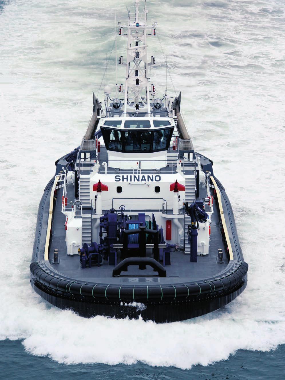
19 2 3 The intelligent propulsion system for safe shipping. An increase in pitch results in a higher maximum efficiency. Unlike with bow thrusters, the steering forces increase as the velocity increases. The flow characteristics of Voith Schneider Propellers are reliably calculated with the numeric flow mechanics method (CFD = Computational Fluid Dynamics). VSPs can be optimized for: Maximum efficiency in open water Maximum bollard pull Minimum power requirement during dynamic positioning and roll stabilization or Optimum hydroacoustic signature 1 Voith Water Tractor Shinano. 2 Pressure distribution on VSP blades (CFD calculation). 3 Calculation mesh: blade discretization. 19
20 VT2070, en, , Vvk, All data and information without obligation. Subject to change. Voith GmbH & Co. KGaA St. Pöltener Straße Heidenheim, Germany Contact: Tel vspmarine@voith.com
DYNAMIC POSITIONING CONFERENCE. October 13-14, Thrusters. Voith Schneider Propeller - An Efficient Propulsion System for DP Controlled Vessels
 Return to Session Directory DYNAMIC POSITIONING CONFERENCE October 13-14, 2009 Thrusters Voith Schneider Propeller - An Efficient Propulsion System for DP Controlled Vessels Dirk Jürgens, Michael Palm
Offshore Hydromechanics Module 1
 Offshore Hydromechanics Module 1 Dr. ir. Pepijn de Jong 6. Real Flows part 2 Introduction Topics of Module 1 Problems of interest Chapter 1 Hydrostatics Chapter 2 Floating stability Chapter 2 Constant
Numerical Investigation of the Performance of Voith Schneider Propulsion
 American Journal of Marine Science, 214, Vol. 2, No. 3, 58-62 Available online at http://pubs.sciepub.com/marine/2/3/3 Science and Education Publishing DOI:12691/marine-2-3-3 Numerical Investigation of
Dimensions of propulsion shafts and their permissible torsional vibration stresses
 (Feb 2005) (orr.1 Mar 2012) (orr.2 Nov 2012) Dimensions of propulsion shafts and their permissible torsional vibration stresses.1 Scope This UR applies to propulsion shafts such as intermediate and propeller
Deliverable D.6.1. Application of CFD tools to the development of a novel propulsion concept
 TRIple Energy Saving by Use of CRP, CLT and PODded Propulsion Grant Agreement Number: 265809 Call identifier: FP7-SST-2010-RTD-1 Theme SST.2010.1.1-2.: Energy efficiency of ships WP 1 Deliverable D.6.1
Comparison of Thruster Axis Tilting versus Nozzle Tilting on the Propeller-Hull Interactions for a Drillship at DP-Conditions
 DYNAMIC POSITIONING CONFERENCE October 12-13, 2010 Thrusters Comparison of Thruster Axis Tilting versus Nozzle Tilting on the Propeller-Hull Interactions for a Drillship at DP-Conditions Michael Palm,
ENGR 4011 Resistance & Propulsion of Ships Assignment 4: 2017
 Question 1a. Values of forward speed, propeller thrust and torque measured during a propeller open water performance test are presented in the table below. The model propeller was 0.21 meters in diameter
Machinery Requirements for Polar Class Ships
 (August 2006) (Rev.1 Jan 2007) (Corr.1 Oct 2007) Machinery Requirements for Polar Class Ships.1 Application * The contents of this Chapter apply to main propulsion, steering gear, emergency and essential
A 954 C HD. Technical Description Hydraulic Excavator. Machine for Industrial Applications
 Technical Description Hydraulic Excavator A 95 C HD litronic` Machine for Industrial Applications Operating Weight 165,800 170,0 lb Engine Output 36 hp (0 kw) Technical Data Engine Rating per ISO 99 0
A Study on Effects of Blade Pitch on the Hydrodynamic Performances of a Propeller by Using CFD
 Journal of Shipping and Ocean Engineering 8 (2018) 36-42 doi 10.17265/2159-5879/2018.01.005 D DAVID PUBLISHING A Study on Effects of Blade Pitch on the Hydrodynamic Performances of a Propeller by Using
Dynamics of Machinery
 Dynamics of Machinery Two Mark Questions & Answers Varun B Page 1 Force Analysis 1. Define inertia force. Inertia force is an imaginary force, which when acts upon a rigid body, brings it to an equilibrium
S.C. Rulmenti S.A. Barlad Romania Republicii Street No
 SELECTION OF BEARING SIZE Basic load ratings The size of a bearing is selected considering the load in the used rolling bearing and also depends on the operational rating life and prescribed operating
IDENTIFICATION OF SHIP PROPELLER TORSIONAL VIBRATIONS
 Journal of KONES Powertrain and Transport, Vol., No. 015 IDENTIFICATION OF SHIP PROPELLER TORSIONAL VIBRATIONS Jan Rosłanowski Gdynia Maritime University, Faculty of Marine Engineering Morska Street 81-87,
Rotor reference axis
 Rotor reference axis So far we have used the same reference axis: Z aligned with the rotor shaft Y perpendicular to Z and along the blade (in the rotor plane). X in the rotor plane and perpendicular do
ITTC Recommended Procedures and Guidelines
 7.5 02 Page 1 of 21 Table of Contents 1 PURPOSE... 2 2 ITTC DICTIONARY OF SHIP HYDRODYNAMICS PROPELLER SECTION... 2 COMMENTS OF THE PROPULSION COMMITTEE OF 22 nd ITTC Several of the symbols and definitions
Fig. 6.1 Plate or disk cam.
 CAMS INTRODUCTION A cam is a mechanical device used to transmit motion to a follower by direct contact. The driver is called the cam and the driven member is called the follower. In a cam follower pair,
Thrusters. Numerical Analysis of Flow Around a Thruster
 Thrusters Numerical Analysis of Flow Around a Thruster Norbert W. H. Bulten Wärtsilä Propulson, Netherlands October 17-18, 2006 Return to Session Directory Numerical Analysis of Flow around a Thruster
Potsdam Propeller Test Case (PPTC) Test Case Description
 Test Case Description") Second International Symposium on Marine Propulsors smp 11, Hamburg, Germany, June 2011 Workshop: Propeller performance Potsdam Propeller Test Case (PPTC) Test Case Description Ulf Barkmann 1, Hans-Jürgen
Second International Symposium on Marine Propulsors smp 11, Hamburg, Germany, June 2011 Workshop: Propeller performance Potsdam Propeller Test Case (PPTC) Test Case Description Ulf Barkmann 1, Hans-Jürgen
UNIT-I (FORCE ANALYSIS)
") DHANALAKSHMI SRINIVASAN INSTITUTE OF RESEACH AND TECHNOLOGY DEPARTMENT OF MECHANICAL ENGINEERING QUESTION BANK ME2302 DYNAMICS OF MACHINERY III YEAR/ V SEMESTER UNIT-I (FORCE ANALYSIS) PART-A (2 marks)
DHANALAKSHMI SRINIVASAN INSTITUTE OF RESEACH AND TECHNOLOGY DEPARTMENT OF MECHANICAL ENGINEERING QUESTION BANK ME2302 DYNAMICS OF MACHINERY III YEAR/ V SEMESTER UNIT-I (FORCE ANALYSIS) PART-A (2 marks)
2 Hydrodynamic characteristics of propeller blades in curvilinear motion. Let, the vertical axis propeller moves ahead with a constant speed V p
 Hydrodynamic characteristics of propeller blades in curvilinear motion Practical application of such methods is of some interest for a straight line motion of the wing. But for calculating dynamic characteristics
Propeller Loads of Large Commercial Vessels at Crash Stop
 Second International Symposium on Marine Propulsors smp 11, Hamburg, Germany, June 2011 Propeller Loads of Large Commercial Vessels at Crash Stop J.W. Hur, H. Lee, B.J. Chang 1 1 Hyundai Heavy Industries,
Balancing of Masses. 1. Balancing of a Single Rotating Mass By a Single Mass Rotating in the Same Plane
 lecture - 1 Balancing of Masses Theory of Machine Balancing of Masses A car assembly line. In this chapter we shall discuss the balancing of unbalanced forces caused by rotating masses, in order to minimize
Cams. 774 l Theory of Machines
 774 l Theory of Machines 0 Fea eatur tures es 1. Introduction.. Classification of Followers. 3. Classification of Cams. 4. Terms used in Radial cams. 5. Motion of the Follower. 6. Displacement, Velocity
ITTC Recommended Procedures and Guidelines Testing and Extrapolation Methods Propulsion, Performance Propulsion Test
 7.5- Page 1 of 13 Table of Contents... 2 1. PURPOSE OF PROCEDURE... 2 2. PARAMETERS... 2 2.1 Data Reduction Equations... 2 2.2 Definition of Variables... 3 3. DESCRIPTION OF PROCEDURE... 3 3.1 Model and
CHAPTER 4 OPTIMIZATION OF COEFFICIENT OF LIFT, DRAG AND POWER - AN ITERATIVE APPROACH
 82 CHAPTER 4 OPTIMIZATION OF COEFFICIENT OF LIFT, DRAG AND POWER - AN ITERATIVE APPROACH The coefficient of lift, drag and power for wind turbine rotor is optimized using an iterative approach. The coefficient
ANALYSIS AND DEVELOPMENT OF A TURBIVO COMPRESSOR FOR MVR APPLICATIONS. Abstract 1. INTRODUCTION
 1275, Page 1 ANALYSIS AND DEVELOPMENT OF A TURBIVO COMPRESSOR FOR MVR APPLICATIONS Elias BOULAWZ KSAYER, Denis CLODIC Center for Energy and Processes, Ecole des Mines de Paris 60, boulevard Saint Michel
WORK SHEET FOR MEP311
 EXPERIMENT II-1A STUDY OF PRESSURE DISTRIBUTIONS IN LUBRICATING OIL FILMS USING MICHELL TILTING PAD APPARATUS OBJECTIVE To study generation of pressure profile along and across the thick fluid film (converging,
ADVANCES IN FULL-SCALE WAKE-FIELD PREDICTIONS AND THE IMPLICATIONS FOR THE PROPELLER DESIGN
 ADVANCES IN FULL-SCALE WAKE-FIELD PREDICTIONS AND THE IMPLICATIONS FOR THE PROPELLER DESIGN Gert-Jan Zondervan*, Bram Starke Maritime Research Institute Netherlands PO Box 28, 67 AA Wageningen, The Netherlands
6.1 Summary of Postgraduate Courses
 Chapter 6 Postgraduate Courses 6.1 Summary of Postgraduate Courses Course No Subject Title Credit Hours Math 6903 Advanced Mathematics 3 NAME 6000 Thesis M.Sc.Engg.: 18 Ph.D.: 45 NAME 6002 Project M.Engg.:
ZIG-ZAG MANEUVER SIMULATION BY CFD FOR A TANKER LIKE VESSEL
 V International Conference on Computational Methods in Marine Engineering MARINE 2013 B. Brinkmann and P. Wriggers (Eds) ZIG-ZAG MANEUVER SIMULATION BY CFD FOR A TANKER LIKE VESSEL G. DUBBIOSO, D. DURANTE,
PLEASURE VESSEL VIBRATION AND NOISE FINITE ELEMENT ANALYSIS
 PLEASURE VESSEL VIBRATION AND NOISE FINITE ELEMENT ANALYSIS 1 Macchiavello, Sergio *, 2 Tonelli, Angelo 1 D Appolonia S.p.A., Italy, 2 Rina Services S.p.A., Italy KEYWORDS pleasure vessel, vibration analysis,
DP MAINTENANCE TRAINING
 DP MAINTENANCE TRAINING SINGAPORE Topics Day 2 Review Introduction to Serial Communications Serial Interface Cards Using the Workstation Diagnostics Screens Practical Applications Discussion of AMC Topics
Full scale thruster performance and load determination based on numerical simulations
 Third International Symposium on Marine Propulsors smp 13, Launceston, Tasmania, Australia, May 213 Full thruster performance and load determination based on numerical simulations Norbert Bulten 1, Rik
PRESSURE DISTRIBUTION AND FRICTION COEFFICIENT OF HYDRODYNAMIC JOURNAL BEARING
 PRESSURE DISTRIBUTION AND FRICTION COEFFICIENT OF HYDRODYNAMIC JOURNAL BEARING 1 Mr.Akash S. Patil, 2 Mr.Kaustubh S. Zambre, 3 Mr.Pramod R. Mali, 4 Prof.N.D.Patil 1,2,3 B.E. Mechanical Dept. P.V.P.I.T,
ME2302 DYNAMICS OF MACHINERY
 ME2302 DYNAMICS OF MACHINERY TWO MARKS QUESTION AND ANSWERS 1. What are the conditions for a body to be in static and dynamic equilibrium? Necessary and sufficient conditions for static and dynamic equilibrium
(Refer Slide Time: 2:43-03:02)
") Strength of Materials Prof. S. K. Bhattacharyya Department of Civil Engineering Indian Institute of Technology, Kharagpur Lecture - 34 Combined Stresses I Welcome to the first lesson of the eighth module
Strength of Materials Prof. S. K. Bhattacharyya Department of Civil Engineering Indian Institute of Technology, Kharagpur Lecture - 34 Combined Stresses I Welcome to the first lesson of the eighth module
Sliding Contact Bearings
 Sliding Contact Bearings Classification of Bearings 1. According to the direction of load to be supported. The bearings under this group are classified as: (a) Radial bearings (b) Thrust bearings. In radial
About One Method of Avoiding Collision with Sailing Objects
 About One Method of Avoiding Collision with Sailing Obects BOGA ŻAK, ZYGMUT KITOWSKI Institute of Electronics and Electrical Engineering aval University 81-919 Gdynia, Smidowicza 69 POLA Abstract: - The
GyroRotor program : user manual
 GyroRotor program : user manual Jean Fourcade January 18, 2016 1 1 Introduction This document is the user manual of the GyroRotor program and will provide you with description of
Si-iö, TH". ()SSS N I. 6-7 Zaf (54) United States Patent (19) Cuff (11 3,968,700. (45) July 13, (21) Appl. No.: 493,748
SSS N I. 6-7 Zaf (54) United States Patent (19) Cuff (11 3,968,700. (45) July 13, (21) Appl. No.: 493,748") United States Patent (19) Cuff (54) DEVICE FOR CONVERTING ROTARY MOTION INTO A UNIDIRECTIONAL LINEAR MOTION 76) Inventor: Calvin I. Cuff, 135 Ocean Ave., Brooklyn, N.Y. 11225 22 Filed: Aug. 1, 1974 (21)
United States Patent (19) Cuff (54) DEVICE FOR CONVERTING ROTARY MOTION INTO A UNIDIRECTIONAL LINEAR MOTION 76) Inventor: Calvin I. Cuff, 135 Ocean Ave., Brooklyn, N.Y. 11225 22 Filed: Aug. 1, 1974 (21)
A NEW WAY OF SIMULATING WHALE TAIL PROPULSION
 A NEW WAY OF SIMULATING WHALE TAIL PROPULSION Written by: J.D. van Manen (Whale Tail Development, The Netherlands) and T. van Terwisga (MARIN, The Netherlands) Presented on 34 th WEGEMT School by: M.X.
HRN/HRN-C Series Hydraulic Vane Rotary Actuators
 HRN/ Hydraulic Vane Rotary Actuators Vane Actuators Tork-Mor HRN Contents Features... 2 Ordering Information... Engineering Data / Specifications... Dimensions... Features... 1 Ordering Information...12
Hidden Potential between the Crankshaft and Valves
 318 319 Hidden Potential between the Crankshaft and Valves W U U M P I Z R W O U Z T W H N E D K U N W P O N C A L E R U I N K O P J E W L S P N Z A D F T O I From E O H the O I optimization O O A N G
Wake fraction and thrust deduction during ship astern manoeuvres
 Wake fraction and thrust deduction during ship astern manoeuvres J. Artyszuk Maritime University of Szczecin, Poland Abstract A relatively small amount of data concerning the behaviour of propulsion coefficients,
Applied Fluid Mechanics
 Applied Fluid Mechanics 1. The Nature of Fluid and the Study of Fluid Mechanics 2. Viscosity of Fluid 3. Pressure Measurement 4. Forces Due to Static Fluid 5. Buoyancy and Stability 6. Flow of Fluid and
Lubrication and Journal Bearings
 UNIVERSITY OF HAIL College of Engineering Department of Mechanical Engineering Chapter 12 Lubrication and Journal Bearings Text Book : Mechanical Engineering Design, 9th Edition Dr. Badreddine AYADI 2016
MODELLING THE DYNAMICS OF SHIPS WITH DIFFERENT PROPULSION SYSTEMS FOR CONTROL PURPOSE
 POLISH MARITIME RESEARCH 1(89) 2016 Vol. 23; pp. 31-36 10.1515/pomr-2016-0005 MODELLING THE DYNAMICS OF SHIPS WITH DIFFERENT PROPULSION SYSTEMS FOR CONTROL PURPOSE Witold Gierusz, Assoc. Prof. Gdynia Maritime
SUMMER 14 EXAMINATION
 Important Instructions to examiners: 1) The answers should be examined by key words and not as word-to-word as given in the model answer scheme. 2) The model answer and the answer written by candidate
The Phenomena of Oil Whirl and Oil Whip
 Ali M. Al-Shurafa, Vibration Engineer Saudi Electricity Company- Ghazlan Power Plant Saudi Arabia ashurafa@hotmail.com The Phenomena of Oil Whirl and Oil Whip 1. Introduction Large machines mounted on
CHAPTER 1 INTRODUCTION Hydrodynamic journal bearings are considered to be a vital component of all the rotating machinery. These are used to support
 CHAPTER 1 INTRODUCTION Hydrodynamic journal bearings are considered to be a vital component of all the rotating machinery. These are used to support radial loads under high speed operating conditions.
API 11E - Specification for Pumping Units
 API 11E - Specification for Pumping Units 5 Beam Pump Structure Requirements 5.1 General Requirements for beam pump structures are specified in the following sections. Only loads imposed on the structure
nozzle which is fitted to a pipe through which the liquid is flowing under pressure.
 Impact of Jets 1. The liquid comes out in the form of a jet from the outlet of a nozzle which is fitted to a pipe through which the liquid is flowing under pressure. The following cases of the impact of
Study of the influence of the resonance changer on the longitudinal vibration of marine propulsion shafting system
 Study of the influence of the resonance changer on the longitudinal vibration of marine propulsion shafting system Zhengmin Li 1, Lin He 2, Hanguo Cui 3, Jiangyang He 4, Wei Xu 5 1, 2, 4, 5 Institute of
Performance Assessment of the Waterjet Propulsion System through a Combined Analytical and Numerical Approach
 International Journal of Physics, 013, Vol. 1, No., -7 Available online at http://pubs.sciepub.com/ijp/1//1 Science and Education Publishing DOI:10.1691/ijp-1--1 Performance Assessment of the Waterjet
Journal of Biomechanical Science and Engineering
 Science and Engineering Bioinspired Propulsion Mechanism in Fluid Using Fin with Dynamic Variable-Effective-Length Spring * Shunichi KOBAYASHI ** Masataka NAKABAYASHI ** and Hirohisa MORIKAWA ** **Department
THE NEW 1.1 MN m TORQUE STANDARD MACHINE OF THE PTB BRAUNSCHWEIG/GERMANY
 THE NEW 1.1 MN m TORQUE STANDARD MACHINE OF THE PTB BRAUNSCHWEIG/GERMANY D. Peschel 1, D. Mauersberger 1, D. Schwind 2, U. Kolwinski 2 1 Solid mechanics department, PTB, Germany 2 Gassmann Theiss Messtechnik
A STUDY INTO RESONANT PHENOMENA IN THE CATAMARAN FERRY PROPULSION SYSTEM
 Ante Šestan Nikola Vladimir Nenad Vulić Boris Ljubenkov ISSN 1333-1124 A STUDY INTO RESONANT PHENOMENA IN THE CATAMARAN FERRY PROPULSION SYSTEM Summary UDC 629.5.015.5 This paper describes the problem
BEARINGS Pillow Blocks
 The bearing size is usually selected according to the required bearing life and reliability under a specified type of load charged on the bearing. The load applied to the bearing operating under a static
Vane Type Rotary Actuators Series Variations
 Vane Type Rotary Actuators Series Variations Vane Type Exterior CRB Series 0,, 0,, CRBU Series 0,, 0,, CRB Series, 6, 80, Has a compact body with exterior dimensions that do not change regardless of the
NATIONAL CERTIFICATE (VOCATIONAL) APPLIED ENGINEERING TECHNOLOGY NQF LEVEL 4 NOVEMBER 2009
 APPLIED ENGINEERING TECHNOLOGY NQF LEVEL 4 NOVEMBER 2009") NATIONAL CERTIFICATE (VOCATIONAL) APPLIED ENGINEERING TECHNOLOGY NQF LEVEL 4 NOVEMBER 2009 (6021024) 30 October (Y-Paper) 13:00 16:00 A non-programmable scientific calculator may be used. This question
NATIONAL CERTIFICATE (VOCATIONAL) APPLIED ENGINEERING TECHNOLOGY NQF LEVEL 4 NOVEMBER 2009 (6021024) 30 October (Y-Paper) 13:00 16:00 A non-programmable scientific calculator may be used. This question
ENGR 4011 Resistance & Propulsion of Ships Assignment 5: A dimensional analysis of propeller thrust starting with the functional expression
 ENGR 40 Resistance & Propulsion of Ships ssignment 5: 07. -dimensional hydrofoil section is shown below. It has an incidence velocity V incidence at an angle of attack α E. For the case shown: sketch the
UNIT 6 GOVERNORS. 6.5 Controlling force and and stability of spring controlled Governors. Compiled By. Dr. B. Suresha, Professor
 UNIT 6 GOVERNORS STRUCTURE 6.1 Introduction 6.1.1 Objectives 6. Types of Governors 6..1 Porter Governor 6.. Hartnell Governor 6.3 Governor effort and Power 6.4 Characteristics of Governors 6.5 Controlling
Autonomous Robotic Vehicles
 Autonomous Robotic Vehicles Ground, Air, Undersea Jim Keller July 15, 2005 Types of Vehicles Ground Wheeled Tracked Legged Crawling/snake Air Fixed wing Powered gliders Rotary wing Flapping wing Morphing
Check-Q-meter. Table of contents. Features. Functions. RE 27551/ /10 Replaces: Type FD
 Check-Q-meter RE /0.0 /0 Replaces: 09.9 Type FD Nominal size... Series ax. Operating pressure 0 bar ax. Flow 0 l/min K9/ Table of contents Contents Page Features Functions Ordering details Symbols Functional
State of the Art Novel InFlow Tech 1Gearturbine 2Imploturbocompressor Development.pdf
 From the SelectedWorks of Carlos Barrera Winter December 21, 2014 State of the Art Novel InFlow Tech 1Gearturbine 2Imploturbocompressor Development.pdf Carlos Barrera Available at: https://works.bepress.com/retrodynamic/4/
WEEKS 2-3 Dynamics of Machinery
 WEEKS 2-3 Dynamics of Machinery References Theory of Machines and Mechanisms, J.J. Uicker, G.R.Pennock ve J.E. Shigley, 2003 Makine Dinamiği, Prof. Dr. Eres SÖYLEMEZ, 2013 Uygulamalı Makine Dinamiği, Jeremy
VIBRATION ANALYSIS IN SHIP STRUCTURES BY FINITE ELEMENT METHOD
 Proceedings of COBEM 2007 Copyright 2007 by ABCM 19th International Congress of Mechanical Engineering November 5-9, 2007, Brasília, DF VIBRATION ANALYSIS IN SHIP STRUCTURES BY FINITE ELEMENT METHOD Luiz
Teaching sessions week 40
 Teaching sessions week 40 Monday 28 September Lecture: Introduction to propulsion. Momentum theory of propeller action. Friday 2 October Lecture: Screw propeller Introduction of Marine Hydrodynamics 1
ElectroMechanical Cylinder LEMC
 www.lmotion.ru lmotionmail@ya.ru.: (9)9160 ElectroMechanical Cylinder LEMC THE POWER OF KNOWLEDGE ENGINEERING www.lmotion.ru lmotionmail@ya.ru.: (9)9160 ElectroMechanical Cylinder LEMC enefits High efficiency
Research on Prediction of Ship Manoeuvrability
 Journal of Shipping and Ocean Engineering 8 (08 30-35 doi 0.765/59-5879/08.0.004 D DAVID PUBLISHING Research on Prediction of Ship Manoeuvrability CUI Jian, WU Zixin and CHEN Weimin Shanghai Ship and Shipping
APPLICATION OF ENERGY SAVING FINS ON RUDDERS
 Proceedings of ASME 25 34th International Conference on Ocean, Offshore and Arctic Engineering OMAE 25 May 3 - June 5, 25, St. John s, Newfoundland, Canada OMAE25-4796 APPLICATION OF ENERGY SAVING FINS
CIRCULAR MOTION AND ROTATION
 1. UNIFORM CIRCULAR MOTION So far we have learned a great deal about linear motion. This section addresses rotational motion. The simplest kind of rotational motion is an object moving in a perfect circle
Fluid structure interaction dynamic analysis of a mixed-flow waterjet pump
 IOP Conference Series: Materials Science and Engineering OPEN ACCESS Fluid structure interaction dynamic analysis of a mixed-flow waterjet pump To cite this article: X W Pan et al 2013 IOP Conf. Ser.:
On the advanced extrapolation method for a new type of podded propulsor via CFD simulations and model measurements
 Fifth International Symposium on Marine Propulsors smp 17, Espoo, Finland, June 2017 On the advanced extrapolation method for a new type of podded propulsor via CFD simulations and model measurements Tomi
STATICS. Friction VECTOR MECHANICS FOR ENGINEERS: Eighth Edition CHAPTER. Ferdinand P. Beer E. Russell Johnston, Jr.
 Eighth E 8 Friction CHAPTER VECTOR MECHANICS FOR ENGINEERS: STATICS Ferdinand P. Beer E. Russell Johnston, Jr. Lecture Notes: J. Walt Oler Texas Tech University Contents Introduction Laws of Dry Friction.
confront fury
 confront WINTER S fury WITH A COTECH SNOW PLOW www.cotech.ca table of content mission...2 Snow Removal Equipment...4 Snow plows with a trip system... 4 Extendable Reversible Snow Plows... 6 Inverted Snow
Consumed. Total. Remaining incl. Tol. AIRCRAFT COMPONENTS 24 - ELECTRICAL POWER Battery OC 363,1 h 4-May-2011
 of Check: 17-Jan-2017 Cycles: 0 ENG 1 N2: 0 Total Hours Cycles AIRCRAFT COMPONENTS 24 - ELECTRICAL POWER Battery OC 363,1 h 4-May-2011 151CH-1 B03441 25 - EQUIPMENT & FURNISHINGS Pilot Crewseat OC 17,0
φ(r, θ, t) = a 2 U(t) cos θ. (7.1)
 = a 2 U(t) cos θ. (7.1)") BioFluids Lectures 7-8: Slender Fish Added Mass for Lateral Motion At high Reynolds number, most of the effort required in swimming is pushing water out of the way, that is our energy goes in providing
BioFluids Lectures 7-8: Slender Fish Added Mass for Lateral Motion At high Reynolds number, most of the effort required in swimming is pushing water out of the way, that is our energy goes in providing
The Calculations of Propeller Induced Velocity by RANS and Momentum Theory
 J. Marine Sci. Appl. (2012) 11: 164-168 DOI: 10.1007/s11804-012-1118-1 The Calculations of Propeller Induced Velocity by RANS and Momentum Theory Qiuxin Gao *, Wei Jin and Dracos Vassalos Department of
PRINCIPLES OF FLIGHT
 1 Considering a positive cambered aerofoil, the pitching moment when Cl=0 is: A infinite B positive (nose-up). C negative (nose-down). D equal to zero. 2 The angle between the aeroplane longitudinal axis
ITTC Recommended Procedures
 7.5-0 -03-0. Page of 6 CONTENTS PURPOSE OF PROCEDURE EXAMPLE FOR OPEN WATER TEST. Test Design. Measurement System and Procedure.3 Uncertainty Analysis.3. ias Limit.3.. Propeller Geometry.3.. Speed of advance
Facts and figures MULTILIFT SELECT 15
 Facts and figures MULTILIFT SELECT 15 www.arburg.com MULTILIFT SELECT 15 Technical data min. 180 Stroke Z-axis Stroke X-axis Clamping face fixed mould platen 220 E A D K Stroke Y axis 195 B 2) C 157 P
Exp All technology at operator s service. Suggested Orange peel. Straight boom m. Industrial straight stick 8.00 m RV 600 2,
 Exp 5055 Exp 5055 All technology at operator s service 0 1 2 3 4 5 6 7 8 9 10 11 12 13 14 15 16 17 18 19 20 0 1 2 3 4 5 6 7 8 9 10 11 12 13 14 15 16 17 18 19 20 20 19 18 17 16 15 14 13 12 11 10 8 9 7 6
Overview. Dry Friction Wedges Flatbelts Screws Bearings Rolling Resistance
 Friction Chapter 8 Overview Dry Friction Wedges Flatbelts Screws Bearings Rolling Resistance Dry Friction Friction is defined as a force of resistance acting on a body which prevents slipping of the body
DUAL-MODE CONTRAPROPELLER WITH CURVE STACKING LINE FOR BLADE
 Anatolij-Branko R. Togunjac, Ph.D, Research and Design Institute for Fishing Fleet, GIPRORYBFLOT, M. Morskaya str.,18-20, St. Petersburg, 190000 Russia Leonid I. Vishnevsky, D.Sc,Krylov Shipbuilding Research
DESIGN OPTIMIZATION STUDY ON A CONTAINERSHIP PROPULSION SYSTEM
 DESIGN OPTIMIZATION STUDY ON A CONTAINERSHIP PROPULSION SYSTEM Brian Cuneo Thomas McKenney Morgan Parker ME 555 Final Report April 19, 2010 ABSTRACT This study develops an optimization algorithm to explore
INPUT DATA FOR TORSIONAL VIBRATION CALCULATIONS (TVC)
") INPUT DATA FOR TORSIONAL VIBRATION CALCULATIONS (TVC) (POWER UNIT FOR MARINE INSTALLATIONS) Name of Vessel / New Building No. Name of Shipyard / Yard No. Name of Owner / Shipping Company Address of Owner
INPUT DATA FOR TORSIONAL VIBRATION CALCULATIONS (TVC) (POWER UNIT FOR MARINE INSTALLATIONS) Name of Vessel / New Building No. Name of Shipyard / Yard No. Name of Owner / Shipping Company Address of Owner
SAMCEF For ROTORS. Chapter 1 : Physical Aspects of rotor dynamics. This document is the property of SAMTECH S.A. MEF A, Page 1
 SAMCEF For ROTORS Chapter 1 : Physical Aspects of rotor dynamics This document is the property of SAMTECH S.A. MEF 101-01-A, Page 1 Table of Contents rotor dynamics Introduction Rotating parts Gyroscopic
A nonlinear dynamic vibration model of defective bearings: The importance of modelling the finite size of rolling elements
 A nonlinear dynamic vibration model of defective bearings: The importance of modelling the finite size of rolling elements Alireza Moazenahmadi, Dick Petersen and Carl Howard School of Mechanical Engineering,
PLANAR RIGID BODY MOTION: TRANSLATION &
 PLANAR RIGID BODY MOTION: TRANSLATION & Today s Objectives : ROTATION Students will be able to: 1. Analyze the kinematics of a rigid body undergoing planar translation or rotation about a fixed axis. In-Class
ORTHOBLOC 3000 Drive systems Maintenance
 15 en 284 261 282 113 130 120 061 002 264 193 099 001 25 063 65 119 112 133 252 254 1 115 118 04 ORTHOBLOC 3000 Maintenance NOTE LEROY-SOMER reserves the right to modify the characteristics of its products
Linear guide drives. Synchronous shafts The use of synchronous shafts enables several linear axes to be operated with one drive.
 Linear guide drives Drive concept The linear guides are driven via the hollow shaft in the drive head. The drive head is used to directly install a motor or alternatively (in connection with a center shaft)
RIGID BODY MOTION (Section 16.1)
") RIGID BODY MOTION (Section 16.1) There are cases where an object cannot be treated as a particle. In these cases the size or shape of the body must be considered. Rotation of the body about its center
RIGID BODY MOTION (Section 16.1) There are cases where an object cannot be treated as a particle. In these cases the size or shape of the body must be considered. Rotation of the body about its center
ElectroMechanical Cylinder LEMC
 ElectroMechanical Cylinder EMC ElectroMechanical Cylinder EMC enefits High eficiency ong service life from use of SKF planetary roller screw Compact and robust structural design Modular concept with multiple
Levers. 558 A Textbook of Machine Design
 558 A Textbook of Machine Design C H A P T E R 15 Levers 1. Introduction.. Application of Levers in Engineering Practice.. Design of a Lever. 4. Hand Lever. 5. Foot Lever. 6. Cranked Lever. 7. Lever for
Performance evaluation of composite marine propeller using L 8 orthogonal array
 Performance evaluation of composite marine propeller using L 8 orthogonal array S.Solomon Raj Dr.P.Ravinder Reddy 2. Assistant professor, department of mechanical engineering, chaitanya bharathi institute
Abstract. 1 Introduction
 Consideration of medium-speed four-stroke engines in ship vibration analyses I. Asmussen, A. Muller-Schmerl GermanischerLloyd, P.O. Box 111606, 20416Hamburg, Germany Abstract Vibration problems were recently
Turbine Meter TRZ 03 PRODUCT INFORMATION. Reliable Measurement of Gas
 Turbine Meter TRZ 0 PRODUCT INFORMATION Reliable Measurement of Gas TURBINE METER TRZ 0 Method of operation, Construction Method of operation The TRZ 0 turbine meter is a flow meter suitable for gas measurement
Theory and Practice of Rotor Dynamics Prof. Rajiv Tiwari Department of Mechanical Engineering Indian Institute of Technology Guwahati
 Theory and Practice of Rotor Dynamics Prof. Rajiv Tiwari Department of Mechanical Engineering Indian Institute of Technology Guwahati Module - 7 Instability in rotor systems Lecture - 4 Steam Whirl and
M O D U L E - 3A Model A10V0 Piston Pump Manual A10V0 PUMP. Features
 T E C H N I C A L I N F O R M A T I O N M A N U A L F O R T H E A 1 0 V 0 V A R I A B L E D I S P L A C E M E N T P U M P S A10V0 PUMP Features High Efficiency through load sensing (= fuel savings) Maximum