SUMMER 14 EXAMINATION
|
|
|
- Jeffry Evans
- 5 years ago
- Views:
Transcription
1 Important Instructions to examiners: 1) The answers should be examined by key words and not as word-to-word as given in the model answer scheme. 2) The model answer and the answer written by candidate may vary but the examiner may try to assess the understanding level of the candidate. 3) The language errors such as grammatical, spelling errors should not be given more Importance (Not applicable for subject English and Communication Skills. 4) While assessing figures, examiner may give credit for principal components indicated in the figure. The figures drawn by candidate and model answer may vary. The examiner may give credit for any equivalent figure drawn. 5) Credits may be given step wise for numerical problems. In some cases, the assumed constant values may vary and there may be some difference in the candidate s answers and model answer. 6) In case of some questions credit may be given by judgement on part of examiner of relevant answer based on candidate s understanding. 7) For programming language papers, credit may be given to any other program based on equivalent concept. Que. No. 1 a) Attempt any SIX 12 i) List of various types of clutches used to transmit Power (FOUR TYPES two marks, each type - half mark) a) Single plate clutch b) Multi plate clutch c) Cone clutch d) Centrifugal clutch ii) Classification of follower: (Two marks, 1 + ½ + ½) 1. According to the surface in contact: Knife-edge follower Roller follower Flat faced or mushroom follower Spherical follower 2. According to the motion of the follower: Reciprocating or translating follower Oscillating or rotating follower 3. According to the path of motion of follower: Page 1 of 28
2 Radial follower Off-set follower iii) (Two marks, 1 + 1) Advantages of chain drive: (any two) 1. As no slip takes place, hence, perfect velocity ratio is obtained (Positive drive). 2. Chain drive gives high transmission efficiency (up to 98 %). 3. Chain drive may be used when the distance between the shafts is less. 4. Chain is made up of metal which would occupy less space as compared with belt or rope drive. 5. Ability to transmit power to several shafts by one chain. 6. Load on the shaft is less and long life. Disadvantages of chain drive: (any two) 1. Manufacturing cost of chains is relatively high 2. The chain drive needs accurate mounting and careful maintenance 3. High velocity fluctuations especially when unduly stretched 4. Chain operations are noisy as compared to belts iv) (Any FOUR TYPES to be written. Two marks, each type - half mark) List of various types bearings used 1. Flat pivot 2. Conical pivot 3. Truncated pivot 4. Single flat collar 5. Multiple flat collar v) (Function to be written. Two marks) The function of governor is to regulate the mean speed of the engine, when there are variations in the load. Governor automatically adjusts and controls the supply of fuel / working fluid to the engine with the varying load conditions and keeps the mean speed within the certain desired limits. e.g. When the load on an engine increases, its speed decreases, therefore it becomes necessary to increase the supply of fuel or working fluid. The configuration of the governor changes and valve is moved to increase the supply of working fluid. Conversely, when the load on the engine Page 2 of 28
3 decreases, its speed increases, and thus, less working fluid is required. Hence, the governor decreases the supply of working fluid. vi) (Definition of fluctuation of speed one mark, fluctuation of energy one mark) Fluctuation of speed: It is the difference between the maximum and minimum speed of Flywheel. Fluctuation of speed = (N 1 N 2 ) rpm N 1 maximum speed, N 2 -- minimum speed Fluctuation of energy: It is the difference between the maximum and minimum energy of Flywheel. Maximum energy of Flywheel I ω 1 2 Minimum energy of Flywheel = I ω 2 2 Fluctuation of energy = I (ω ω 2 2 ) in N-m or J I moment of inertia of flywheel = mk 2 where, m mass of the flywheel, kg and k - radius of gyration of flywheel, m 2 ω 1 Maximum Angular velocity, rad/sec ω 2 Minimum Angular velocity, rad/sec vii) (Any FOUR TYPES to be written. Two marks, each type - half mark) Types of brakes: Based on actuation or means of transforming energy: 1. Hydraulic brakes 2. Electric brakes 3. Mechanical brakes 4. Pneumatic brakes Based on the direction of acting force: Radial brakes External a) shoe brake b) band brake c) band and block brake Page 3 of 28
4 Internal a) Internal expanding brake Axial or disc brakes viii) Balancing meaning one mark, methods one mark (any two methods) The process of providing the second mass in order to counter act the effect of the centrifugal force of the disturbing mass is called balancing. In order to prevent the bad effect of centrifugal force of disturbing mass, another mass (balancing) is attached to the opposite side of the shaft at such a position, so as to balance the effect of centrifugal force of disturbing mass. This is done in such a way that the centrifugal forces of both the masses are made equal and opposite. Methods of balancing: Balancing of rotating masses 1) Balancing of a single rotating mass by a single rotating mass in the same plane 2) Balancing of a single rotating mass by two masses rotating in the different planes * Disturbing mass lies in a plane between the planes of balancing masses * Disturbing mass lies in a plane on one end of the planes of balancing masses 3) Balancing of different masses rotating in the same plane 4) Balancing of different masses rotating in the different planes Balancing of reciprocating masses Que. No. 1 b) Attempt any TWO i) (Definition of Kinematic pair One mark, Types Three marks) Kinematic pair: When two kinematic links or elements are in contact with each other such that relative motion between them is either completely constrained or successfully constrained. Types: Based on nature of relative motion Sliding pair / Prismatic pair Turning pair / Revolute pair Screw pair / Helical pair Spherical pair / Globular pair Rolling pair Based on nature of contact Page 4 of 28
5 Lower pair Higher pair Based on nature of closure Self closed pair Force- closed pair ii) (Types of clutches: Two marks, applications Two marks) Types of clutches: a) Single plate clutch b) Multi plate clutch c) Cone clutch d) Centrifugal clutch Applications: a) Single plate clutch: Heavy vehicles, four-wheeler such as car, truck, bus b) Multi plate clutch: Two wheelers, mopeds, scooters, bikes c) Cone clutch: Machine tools, automobiles, press work d) Centrifugal clutch: mopeds, Luna iii) One application ONE mark V- Belt drive air compressor, machine tools (drilling machine) Flat belt drive - lathe headstock, floor mill, stone crusher unit Gear drive gear box of vehicles, cement mixing unit, machine tools, I.C. Engine, differential of automobile, dial indicator Chain drive Bicycle, cranes, Hoists, bikes Que. No. 2 Attempt any FOUR 16 a) (Any Four points - four marks) Sl. No. Machine Structure 1 All parts / links have relative motion No relative motion between the links 2 It transforms the available energy into some useful work No energy transformations Page 5 of 28
6 3 The kinematic link of a machine may transmit both power and motion The member of the structure transmit forces only 4 Examples: I.C. Engine, Machine tools, steam engine, type writer, etc. Example: Truss of roof, frame of machine, truss of bridge 5 Studied under 'Dynamics' Studied under 'Statics' b) (Sketch 2 marks, explanation 2 marks) Crank and slotted lever quick return motion mechanism. This mechanism is mostly used in shaping machines, slotting machines and in rotary internal combustion engines. In this mechanism, the link AC (i.e. link 3) forming the turning pair is fixed, as shown in fig. The link 3 corresponds to the connecting rod of a reciprocating steam engine. The driving crank CB revolves with uniform angular speed about the fixed centre C. A sliding block attached to the crank pin at B slides along the slotted bar AP and thus causes AP to oscillate about the pivoted point A. A short link PR transmits the motion from AP to the ram which carries the tool and reciprocates along the line of stroke R1R2. The line of stroke of the ram (i.e. R1R2) is perpendicular to AC produced In the extreme positions, AP1 and AP2 are tangential to the circle and the cutting tool is at the end of the stroke. The forward or cutting stroke occurs when the crank rotates from the position CB1 to CB2 (or through an angle β) in the clockwise direction. The return stroke occurs when the Page 6 of 28
7 crank rotates from the position CB2 to CB1 (or through angle α) in the clockwise direction. Since the crank has uniform angular speed, c) (one mark each for stating formulae for velocity and acceleration of piston & connecting rod) Velocity of piston, V p = ω r ( + ) State all the terms: ω = angular velocity of the crank, rad/sec n = Ratio of length of connecting rod to the radius of crank = l / r (Obliquity of connecting rod) θ = Angle made by the crank with Inner Dead Centre (IDC) r = radius of crank, l = length of connecting rod Acceleration of piston, A p = ω 2 r + Angular velocity of connecting rod Page 7 of 28
8 Angular acceleration of connecting rod, α cr = - ω 2 d) (Sketch 3 marks, explanation 1 mark) Let OC be the crank and PC the connecting rod of a reciprocating steam engine, as shown in Fig. Let the crank makes an angle θ with the line of stroke PO and rotates with uniform angular velocity ω rad/s in a clockwise direction. The Klien s velocity and acceleration diagrams are drawn as discussed below: Klien s velocity diagram First of all, draw OM perpendicular to OP; such that it intersects the line PC produced at M. The triangle OCM is known as Klien s velocity diagram. In this triangle OCM, OM may be regarded as a line perpendicular to PO, CM may be regarded as a line parallel to PC, and...(_it is the same line.) CO may be regarded as a line parallel to CO. The velocity diagram for given configuration is a triangle ocp Page 8 of 28

9 e) Any Four reasons four marks Roller follower is preferred over knife edge follower Knife-edge of the follower will cause the wear of the cam. Higher load on the small contact area the follower likely to cause wear at the tip of Knifeedge due to more stresses. Knife-edge follower practically not feasible for higher torque / load applications. More friction due to sliding motion of the knife-edge follower and hence, more maintenance. Roller follower on the other hand produces smooth operation with less wear and tear of both cam and follower. Pure rotational motion of roller follower causes less friction and less loss of power. Considerable side thrust exists between knife-edge follower and the guide. Page 9 of 28
10 f) Data: Initial tension, T o = 2000 N, coefficient of friction, µ = 0.3, Angle of lap, θ = = x П / 180 = rad, Smaller pulley radius, R = 200 mm, hence, D = 400 mm, Speed of smaller pulley, N = 500 r.p.m. We know that the velocity of the belt, v = П = П = m/sec (01 mark) Let T 1 = Tension in the belt on the tight side, N Let T 2 = Tension in the belt on the slack side, N We know that, T 0 = Hence, 2000 = (T 1 + T 2 ) / 2 Thus, (T 1 + T 2 ) = 4000 N... (1) We also know that, = therefore, = or = (2) From equations 1 and 2, T 1 = 2750 N and T2 = 1250 N (02 marks) Power transmitted by belt, P = [T 1 - T 2 ] v = [ ] = watts = 15.7 kw (01 mark) Q3 a) For Space diagram 01 Mark, Velocity Diagram 02 marks, Calculations 01 Mark ( Note In QP length BC & AB are equal. Read length AD = length BC = 150 mm) Page 10 of 28
11 Q3 b) For Space diagram 01 Mark, Velocity Diagram 01 marks,accln Diagram 01 Mark & Calculations 01 Mark Page 11 of 28
12 In order to find the velocity of the midpoint D of the connecting rod AB, divide the vector ba at d in the same ratio as D divides AB, in the space diagram. In other words, bd / ba = BD/BA Note: Since D is the midpoint of AB, therefore d is also midpoint of vector ba. Join od. Now the vector od represents the velocity of the midpoint D of the connecting rod i.e. v D. By measurement, we find that v D = vector od = 4.1 m/s In order to find the acceleration of the midpoint D of the connecting rod AB, divide the vector a' b' at d' in the same ratio as D divides AB. In other words Note: Since D is the midpoint of AB, therefore d' is also midpoint of vector b' a'. Join o' d'. The vector o' d' represents the acceleration of midpoint D of the connecting rod i.e. a D. By measurement, we find that a D = vector o' d' = 117 m/s 2 Page 12 of 28


13 Q3 c) For Types 01 Mark, Explain any one type with figure 03 marks Following are the different types of gear trains, depending upon the arrangement of wheels : 1. Simple gear train, 2. Compound gear train, 3. Reverted gear train, and 4. Epicyclic gear train. Page 13 of 28
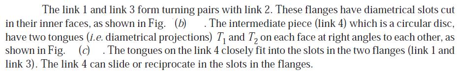
 are fastened to the driven shaft to permit axial motion (except for the last disc).")
14 Q3 d) For Labeled sketch 02 Mark, Brief working 02 marks A multiple disc clutch, as shown in Fig., may be used when a large torque is to be transmitted. The inside discs (usually of steel) are fastened to the driven shaft to permit axial motion (except for the last disc). The outside discs (usually of bronze) are held by bolts and are fastened to the housing which is keyed to the driving shaft. The multiple disc clutches are extensively used in motor cars, machine tools etc. Let n 1 = Number of discs on the driving shaft, and n 2 = Number of discs on the driven shaft. Number of pairs of contact surfaces, n = n 1 + n 2 1 and total frictional torque acting on the friction surfaces or on the clutch, Page 14 of 28
15 Q3 e) For Diagrams 02 Mark, Method 02 marks Page 15 of 28
16 f) For follower motions 02 Mark, for cam motions 02 marks The follower, during its travel, may have one of the following motions. 1. Uniform velocity, 2. Simple harmonic motion, 3. Uniform acceleration and retardation, 4. Cycloidal motion. In addition follower may have 1. Translatory motion 2. Oscillating motion Also the cam may have one of the following motions 1. Rotary motion ( as in radial / cylindrical cam) 2. Linear motion ( as in wedge cam) Q4 a) For equation 02 Mark, for terms 02 marks Where T 1 = Tension in the belt on the tight side, T 2 = Tension in the belt on the slack side, and Ѳ = Angle of contact or lap in radians i.e angle subtended by the belt arc lapping over small pulley. Page 16 of 28
17 Q4 b) For sketch 02 Mark, for explanation 02 marks Since slider A forms first sliding pair with its groove( guide) and slider B forms second sliding pair with its groove ( guide), this mechanism falls under double slider mechanism. Page 17 of 28
18 Q4 c) For sketch 02 Mark, for explanation 02 marks Page 18 of 28
19 Q4 d) For sketch 02 Mark, for explanation 02 marks Eddy Current Dynamometer : It consists of a stator on which are fitted a number of electromagnets and a rotor disc made of copper or steel and coupled to the output shaft of the engine. When the rotor rotates, eddy currents are produced in the stator due to magnetic flux set up by the passage of field current in the electromagnets. These eddy currents oppose the motion of the rotor thus loading the engine. The eddy currents are dissipated in producing heat so that this type of dynamometer also requires some cooling arrangements. The torque is measured similar to absorption dynamometers i.e. with the help of moment arm. The load is controlled by regulating the current in the electromagnets. Page 19 of 28
20 Q4 e) For W, R, T & P each 01 Mark Q4 f) For space diagram 01 Mark, Vector diagram 02 mark, Show resultant 01 Mark Page 20 of 28
21 Q 5 (a) For Space diagram 01 Mark, Velocity diagram02 Marks, Accln diagram 03 Marks, Calculations 02 Marks Page 21 of 28


22 Q 5 (b) Displacement diagram 03 Marks, Cam Profile 05 Marks Page 22 of 28


23 Q 5 c) For T1 & T2 : 02 Marks, For Min belt width: 02 Marks, Initial Belt tension: 02 Marks, Belt length : 02 Marks Page 23 of 28
24 Page 24 of 28
 It regulates fluctuation of speed when there is a")
 It acts by virtue of its inertia iii) It acts as a mechanism to control fuel supply iv) If torque variation is high, flywheel size required is larger iv) If external load")
25 Q 6 (a) (i) Sketch 02 Marks, Explanation 02 Marks Q 6 (a) (ii) Any four points 04 Marks Flywheel Governor i) Flywheel is a device which stores i) Governor is a device controls the supply of energy when produced in excess & of fuel to engine & controls mean speed release when required by m/c ii) It regulates fluctuation of speed when there is a variation in cyclic torque of m/c ii ) It regulates speed of engine when there is a external load variation. iii) It acts by virtue of its inertia iii) It acts as a mechanism to control fuel supply iv) If torque variation is high, flywheel size required is larger iv) If external load variation is higher, more control on fuel supply necessary Page 25 of 28
 Sketch 02 Marks, Clockwise & Anticlockwise rotations each 03 Marks Page 26 of")
26 v) Used in Engines, forging m/c, Sheet v) Used in Engines metal press, shearing m/c Q 6 (b) Sketch 02 Marks, Clockwise & Anticlockwise rotations each 03 Marks Page 26 of 28
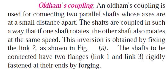
27 Q 6 (c) List 01 Marks, Sketch 04 Marks, explanation 03 Marks Inversions of double slider crank mechanism: (i) Elliptical Trammels (ii) Scotch Yoke Mechanism (iii) Oldham s Coupling. Page 27 of 28

28 Page 28 of 28
Q.1 a) any six of the following 6x2= 12. i) Define - ( Each term 01 mark)
 any six of the following 6x2= 12. i) Define - ( Each term 01 mark)") Important Instructions to examiners: 1) The answers should be examined by key words and not as word-to-word as given in the model answer scheme. 2) The model answer and the answer written by candidate
Important Instructions to examiners: 1) The answers should be examined by key words and not as word-to-word as given in the model answer scheme. 2) The model answer and the answer written by candidate
Dynamics Plane kinematics of rigid bodies Section 4: TJW Rotation: Example 1
 Section 4: TJW Rotation: Example 1 The pinion A of the hoist motor drives gear B, which is attached to the hoisting drum. The load L is lifted from its rest position and acquires an upward velocity of
UNIT II Fig (1) Fig (1)
 Fig (1)") UNIVERSITY OF PUNE [4362]-116 S.E.(Mechanical / Automobile) Examination 2013 (2008 pattern) THEY OF MACHINES -1 [Total No. of Questions: 12] [Total No. of Printed pages: 7] [Time: 4 Hours] [Max. Marks:
UNIVERSITY OF PUNE [4362]-116 S.E.(Mechanical / Automobile) Examination 2013 (2008 pattern) THEY OF MACHINES -1 [Total No. of Questions: 12] [Total No. of Printed pages: 7] [Time: 4 Hours] [Max. Marks:
The principle of the flywheel is found before the many centuries ago in spindle and the potter's wheel.
 TOM Fly Wheel Mechanical Engineering Department The principle of the flywheel is found before the many centuries ago in spindle and the potter's wheel. A heavy-rimmed rotating wheel used to minimize variations
Attempt any SIX of the following. Different mechanism generated by single slider crank chain mechanism. (Any four)
") Important Instructions to examiners: 1) The answers should be examined by key words and not as word-to-word as given in the model answer scheme. 2) The model answer and the answer written by candidate
Important Instructions to examiners: 1) The answers should be examined by key words and not as word-to-word as given in the model answer scheme. 2) The model answer and the answer written by candidate
Cams. 774 l Theory of Machines
 774 l Theory of Machines 0 Fea eatur tures es 1. Introduction.. Classification of Followers. 3. Classification of Cams. 4. Terms used in Radial cams. 5. Motion of the Follower. 6. Displacement, Velocity
EDEXCEL NATIONAL CERTIFICATE/DIPLOMA ADVANCED MECHANICAL PRINCIPLES AND APPLICATIONS UNIT 18 NQF LEVEL 3
 EDEXCEL NATIONAL CERTIFICATE/DIPLOMA ADVANCED MECHANICAL PRINCIPLES AND APPLICATIONS UNIT 18 NQF LEVEL 3 OUTCOME 3 BE ABLE TO DETERMINE RELATIVE AND RESULTANT VELOCITY IN ENGINEERING SYSTEMS Resultant
UNIT 2 KINEMATICS OF LINKAGE MECHANISMS
 UNIT 2 KINEMATICS OF LINKAGE MECHANISMS ABSOLUTE AND RELATIVE VELOCITY An absolute velocity is the velocity of a point measured from a fixed point (normally the ground or anything rigidly attached to the
Chapter 8 Acceleration in Mechanisms
 Chapter 8 Acceleration in Mechanisms 1 2 8.2. Acceleration Diagram for a Link Example 8.1 3 The crank of a slider crank mechanism rotates cw at a constant speed of 300 rpm. The crank is 150 mm & the ConRod
Fig. 6.1 Plate or disk cam.
 CAMS INTRODUCTION A cam is a mechanical device used to transmit motion to a follower by direct contact. The driver is called the cam and the driven member is called the follower. In a cam follower pair,
10/23/2015. Chapter 7. Velocity in Mechanisms. (Relative Velocity Method) Mohammad Suliman Abuhaiba, Ph.D., PE
 Mohammad Suliman Abuhaiba, Ph.D., PE") Chapter 7 Velocity in Mechanisms (Relative Velocity Method) 1 2 7.2. Relative Velocity of Two Bodies Moving in Straight Lines 3 7.3. Motion of a Link Velocity of any point on a link wrt another point on
Chapter 7 Velocity in Mechanisms (Relative Velocity Method) 1 2 7.2. Relative Velocity of Two Bodies Moving in Straight Lines 3 7.3. Motion of a Link Velocity of any point on a link wrt another point on
The University of Melbourne Engineering Mechanics
 The University of Melbourne 436-291 Engineering Mechanics Tutorial Eleven Instantaneous Centre and General Motion Part A (Introductory) 1. (Problem 5/93 from Meriam and Kraige - Dynamics) For the instant
PLANAR RIGID BODY MOTION: TRANSLATION &
 PLANAR RIGID BODY MOTION: TRANSLATION & Today s Objectives : ROTATION Students will be able to: 1. Analyze the kinematics of a rigid body undergoing planar translation or rotation about a fixed axis. In-Class
CLUTCHES AND BRAKES. Square-jaw clutch
 Clutches: CLUTCHES AND BRAKES A Clutch is a mechanical device which is used to connect or disconnect the source of power from the remaining parts so the power transmission system at the will of the operator.
Inertia Forces in a Reciprocating Engine, Considering the Weight of Connecting Rod.
 Inertia Forces in a Reciprocating Engine, Considering the Weight of Connecting Rod. We use equivalent mass method. let OC be the crank and PC, the connecting rod whose centre of gravity lies at G. We will
MECHANICAL ENGINEERING
 MECHNICL ENGINEERING ESE TOPICWISE OBJECTIVE SOLVED PPER-II FROM (1995-017) UPSC Engineering Services Examination State Engineering Service Examination & Public Sector Examination. IES MSTER PUBLICTION
Flywheels-Function need and Operation
 STUDY OF FLYWHEEL Flywheel definition A flywheel is an inertial energy-storage device. It absorbs mechanical energy and serves as a reservoir, storing energy during the period when the supply of energy
Balancing of Masses. 1. Balancing of a Single Rotating Mass By a Single Mass Rotating in the Same Plane
 lecture - 1 Balancing of Masses Theory of Machine Balancing of Masses A car assembly line. In this chapter we shall discuss the balancing of unbalanced forces caused by rotating masses, in order to minimize
Inertia Forces in Reciprocating. Parts. 514 l Theory of Machines
 514 l Theory of Machines 15 Features 1. Introduction.. Resultant Effect of a System of Forces Acting on a Rigid Body. 3. D-Alembert s Principle. 4. Velocity and Acceleration of the Reciprocating Parts
THEORY OF MACHINES I
 THEORY OF MACHINES I (Kinematics of Machines) (In SI Units) For BE/B.Tech. 3rd YEAR (Strictly as per the latest syllabus prescribed by U.P.T.U., U.P.) By Dr. R.K. BANSAL B.Sc. Engg. (Mech.), M.Tech., Hons.
UNIT 4 FLYWHEEL 4.1 INTRODUCTION 4.2 DYNAMICALLY EQUIVALENT SYSTEM. Structure. Objectives. 4.1 Introduction
 UNIT 4 FLYWHEEL Structure 4.1 Introduction Objectives 4. Dynamically Equivalent System 4.3 Turning Moment Diagram 4.3.1 Turning Moment Diagram of a Single Cylinder 4-storke IC Engine 4.3. Turning Moment
DYNAMICS ME HOMEWORK PROBLEM SETS
 DYNAMICS ME 34010 HOMEWORK PROBLEM SETS Mahmoud M. Safadi 1, M.B. Rubin 2 1 safadi@technion.ac.il, 2 mbrubin@technion.ac.il Faculty of Mechanical Engineering Technion Israel Institute of Technology Spring
LABORATORY MANUAL DYNAMICS OF MACHINE ME-314-E
 LABORATORY MANUAL DYNAMICS OF MACHINE ME-314-E 1 LIST OF EXPERIMENTS S. No. NAME OF EXPERIMENTS PAGE No. 1. To perform experiment on watt and Porter Governors to prepare performance characteristic Curves,
Brakes and Dynamometers
 73 l Theory of Machines 19 Features 1. Introduction. Materials for Brake Lining. 3. Types of Brakes. 4. Single Block or Shoe Brake. 5. Pivoted Block or Shoe Brake. 6. Double Block or Shoe Brake. 7. Simple
KINGS COLLEGE OF ENGINEERING ENGINEERING MECHANICS QUESTION BANK UNIT I - PART-A
 KINGS COLLEGE OF ENGINEERING ENGINEERING MECHANICS QUESTION BANK Sub. Code: CE1151 Sub. Name: Engg. Mechanics UNIT I - PART-A Sem / Year II / I 1.Distinguish the following system of forces with a suitable
ME 6505 DYNAMICS OF MACHINES Fifth Semester Mechanical Engineering (Regulations 2013)
") ME 6505 DYNAMICS OF MACHINES Fifth Semester Mechanical Engineering (Regulations 2013) Unit II PART A 1. Define static balancing of shaft. (N/D 15) The net dynamic force acting on the shaft is equal to
ME 6505 DYNAMICS OF MACHINES Fifth Semester Mechanical Engineering (Regulations 2013) Unit II PART A 1. Define static balancing of shaft. (N/D 15) The net dynamic force acting on the shaft is equal to
Final Exam April 30, 2013
 Final Exam Instructions: You have 120 minutes to complete this exam. This is a closed-book, closed-notes exam. You are allowed to use a calculator during the exam. Usage of mobile phones and other electronic
Varuvan Vadivelan. Institute of Technology LAB MANUAL. : 2013 : B.E. MECHANICAL ENGINEERING : III Year / V Semester. Regulation Branch Year & Semester
 Varuvan Vadivelan Institute of Technology Dharmapuri 636 703 LAB MANUAL Regulation Branch Year & Semester : 2013 : B.E. MECHANICAL ENGINEERING : III Year / V Semester ME 6511 - DYNAMICS LABORATORY GENERAL
STATICS. Friction VECTOR MECHANICS FOR ENGINEERS: Eighth Edition CHAPTER. Ferdinand P. Beer E. Russell Johnston, Jr.
 Eighth E 8 Friction CHAPTER VECTOR MECHANICS FOR ENGINEERS: STATICS Ferdinand P. Beer E. Russell Johnston, Jr. Lecture Notes: J. Walt Oler Texas Tech University Contents Introduction Laws of Dry Friction.
Phys101 Lectures 19, 20 Rotational Motion
 Phys101 Lectures 19, 20 Rotational Motion Key points: Angular and Linear Quantities Rotational Dynamics; Torque and Moment of Inertia Rotational Kinetic Energy Ref: 10-1,2,3,4,5,6,8,9. Page 1 Angular Quantities
UNIT 6 GOVERNORS. 6.5 Controlling force and and stability of spring controlled Governors. Compiled By. Dr. B. Suresha, Professor
 UNIT 6 GOVERNORS STRUCTURE 6.1 Introduction 6.1.1 Objectives 6. Types of Governors 6..1 Porter Governor 6.. Hartnell Governor 6.3 Governor effort and Power 6.4 Characteristics of Governors 6.5 Controlling
TOPIC D: ROTATION EXAMPLES SPRING 2018
 TOPIC D: ROTATION EXAMPLES SPRING 018 Q1. A car accelerates uniformly from rest to 80 km hr 1 in 6 s. The wheels have a radius of 30 cm. What is the angular acceleration of the wheels? Q. The University
VALLIAMMAI ENGINEERING COLLEGE SRM NAGAR, KATTANKULATHUR DEPARTMENT OF MECHANICAL ENGINEERING
 VALLIAMMAI ENGINEERING COLLEGE SRM NAGAR, KATTANKULATHUR 603203 DEPARTMENT OF MECHANICAL ENGINEERING BRANCH: MECHANICAL YEAR / SEMESTER: I / II UNIT 1 PART- A 1. State Newton's three laws of motion? 2.
UNIT-I (FORCE ANALYSIS)
") DHANALAKSHMI SRINIVASAN INSTITUTE OF RESEACH AND TECHNOLOGY DEPARTMENT OF MECHANICAL ENGINEERING QUESTION BANK ME2302 DYNAMICS OF MACHINERY III YEAR/ V SEMESTER UNIT-I (FORCE ANALYSIS) PART-A (2 marks)
DHANALAKSHMI SRINIVASAN INSTITUTE OF RESEACH AND TECHNOLOGY DEPARTMENT OF MECHANICAL ENGINEERING QUESTION BANK ME2302 DYNAMICS OF MACHINERY III YEAR/ V SEMESTER UNIT-I (FORCE ANALYSIS) PART-A (2 marks)
UNIT 3 Friction and Belt Drives 06ME54. Structure
 UNIT 3 Friction and Belt Drives 06ME54 Structure Definitions Types of Friction Laws of friction Friction in Pivot and Collar Bearings Belt Drives Flat Belt Drives Ratio of Belt Tensions Centrifugal Tension
For 2014 (IES, GATE & PSUs) Theory of Machines
 Theory of Machines") For 014 (IES, GATE & PSUs) Theory of Machines Contents Chapter 1: Mechanisms Chapter - : Flywheel Chapter - 3 : Governor Chapter - 4 : CAM Chapter - 5 : Balancing of Rigid Rotors and Field Balancing Chapter
For 014 (IES, GATE & PSUs) Theory of Machines Contents Chapter 1: Mechanisms Chapter - : Flywheel Chapter - 3 : Governor Chapter - 4 : CAM Chapter - 5 : Balancing of Rigid Rotors and Field Balancing Chapter
6. Find the net torque on the wheel in Figure about the axle through O if a = 10.0 cm and b = 25.0 cm.
 1. During a certain period of time, the angular position of a swinging door is described by θ = 5.00 + 10.0t + 2.00t 2, where θ is in radians and t is in seconds. Determine the angular position, angular
OUTCOME 1 MECHANICAL POWER TRANSMISSION SYSTEMS TUTORIAL 3 FLYWHEELS. On completion of this short tutorial you should be able to do the following.
 Unit 60: Dynamics of Machines Unit code: H/60/4 QCF Level:4 Credit value:5 OUTCOME MECHANCAL POWER TRANSMSSON SYSTEMS TUTORAL 3 FLYWHEELS. Be able to determine the kinetic and dynamic parameters of mechanical
Kinematics of. Motion. 8 l Theory of Machines
 8 l Theory of Machines Features 1. 1ntroduction.. Plane Motion. 3. Rectilinear Motion. 4. Curvilinear Motion. 5. Linear Displacement. 6. Linear Velocity. 7. Linear Acceleration. 8. Equations of Linear
CHAPTER 8: ROTATIONAL OF RIGID BODY PHYSICS. 1. Define Torque
 7 1. Define Torque 2. State the conditions for equilibrium of rigid body (Hint: 2 conditions) 3. Define angular displacement 4. Define average angular velocity 5. Define instantaneous angular velocity
CHIEF ENGINEER REG III/2 APPLIED MECHANICS
 CHIEF ENGINEER REG III/2 APPLIED MECHANICS LIST OF TOPICS A B C D E F G H I J Vector Representation Statics Friction Kinematics Dynamics Machines Strength of Materials Hydrostatics Hydrodynamics Control
UNIT 5 GOVERNORS 5.1 INTRODUCTION. Structure. 5.1 Introduction. 5.2 Classification of Governors 5.3 Gravity Controlled Centrifugal Governors
 UNIT 5 GVERNRS Governors Structure 5. Introduction bjectives 5. lassification of Governors 5.3 Gravity ontrolled entrifugal Governors 5.3. Watt Governor 5.3. Porter Governor 5.4 Spring ontrolled entrifugal
PhysicsAndMathsTutor.com 1
 PhysicsAndMathsTutor.com 1 Q1. A grinding wheel is used to sharpen chisels in a school workshop. A chisel is forced against the edge of the grinding wheel so that the tangential force on the wheel is a
COMPUTER AIDED MODELLING AND POSITION ANALYSIS OF CRANK AND SLOTTED LEVER MECHANISM
 International Journal of Mechanical and Production Engineering Research and Development (IJMPERD ) ISSN 2249-6890 Vol.2, Issue 2 June 2012 47-52 TJPRC Pvt. Ltd., COMPUTER AIDED MODELLING AND POSITION ANALYSIS
DEPARTMENT OF MECHANICAL ENGINEERING Dynamics of Machinery. Submitted
 DEPARTMENT OF MECHANICAL ENGINEERING Dynamics of Machinery Submitted 1 UNIT I - Force Analysis INDEX (1) Introduction (2) Newton s Law (3) Types of force Analysis (4) Principle of Super Position (5) Free
TUTORIAL SHEET 1. magnitude of P and the values of ø and θ. Ans: ø =74 0 and θ= 53 0
 TUTORIAL SHEET 1 1. The rectangular platform is hinged at A and B and supported by a cable which passes over a frictionless hook at E. Knowing that the tension in the cable is 1349N, determine the moment
Dept of ECE, SCMS Cochin
 B B2B109 Pages: 3 Reg. No. Name: APJ ABDUL KALAM TECHNOLOGICAL UNIVERSITY SECOND SEMESTER B.TECH DEGREE EXAMINATION, MAY 2017 Course Code: BE 100 Course Name: ENGINEERING MECHANICS Max. Marks: 100 Duration:
Plane Motion of Rigid Bodies: Forces and Accelerations
 Plane Motion of Rigid Bodies: Forces and Accelerations Reference: Beer, Ferdinand P. et al, Vector Mechanics for Engineers : Dynamics, 8 th Edition, Mc GrawHill Hibbeler R.C., Engineering Mechanics: Dynamics,
This equation of motion may be solved either by differential equation method or by graphical method as discussed below:
 2.15. Frequency of Under Damped Forced Vibrations Consider a system consisting of spring, mass and damper as shown in Fig. 22. Let the system is acted upon by an external periodic (i.e. simple harmonic)
acceleration weight load
 Instructions for Vocabulary Cards: Please photocopy the following pages onto heavy card stock (back to back, so the word is printed on the back side of the matching definition). Then, laminate each page.
 第 1 頁, 共 7 頁 Chap10 1. Test Bank, Question 3 One revolution per minute is about: 0.0524 rad/s 0.105 rad/s 0.95 rad/s 1.57 rad/s 6.28 rad/s 2. *Chapter 10, Problem 8 The angular acceleration of a wheel
Unit 8 Notetaking Guide Torque and Rotational Motion
 Unit 8 Notetaking Guide Torque and Rotational Motion Rotational Motion Until now, we have been concerned mainly with translational motion. We discussed the kinematics and dynamics of translational motion
Name: Date: Period: AP Physics C Rotational Motion HO19
 1.) A wheel turns with constant acceleration 0.450 rad/s 2. (9-9) Rotational Motion H19 How much time does it take to reach an angular velocity of 8.00 rad/s, starting from rest? Through how many revolutions
OUTCOME 2 KINEMATICS AND DYNAMICS
 Unit 60: Dynamics of Machines Unit code: H/601/1411 QCF Level:4 Credit value:15 OUTCOME 2 KINEMATICS AND DYNAMICS TUTORIAL 3 GYROSCOPES 2 Be able to determine the kinetic and dynamic parameters of mechanical
Physics for Scientist and Engineers third edition Rotational Motion About a Fixed Axis Problems
 A particular bird s eye can just distinguish objects that subtend an angle no smaller than about 3 E -4 rad, A) How many degrees is this B) How small an object can the bird just distinguish when flying
RIGID BODY MOTION (Section 16.1)
") RIGID BODY MOTION (Section 16.1) There are cases where an object cannot be treated as a particle. In these cases the size or shape of the body must be considered. Rotation of the body about its center
RIGID BODY MOTION (Section 16.1) There are cases where an object cannot be treated as a particle. In these cases the size or shape of the body must be considered. Rotation of the body about its center
Chapter 8 Lecture Notes
 Chapter 8 Lecture Notes Physics 2414 - Strauss Formulas: v = l / t = r θ / t = rω a T = v / t = r ω / t =rα a C = v 2 /r = ω 2 r ω = ω 0 + αt θ = ω 0 t +(1/2)αt 2 θ = (1/2)(ω 0 +ω)t ω 2 = ω 0 2 +2αθ τ
Advanced Higher Physics. Rotational motion
 Wallace Hall Academy Physics Department Advanced Higher Physics Rotational motion Problems AH Physics: Rotational Motion 1 2013 Data Common Physical Quantities QUANTITY SYMBOL VALUE Gravitational acceleration
Theory of Machines. 1. Mechanism. 2. Cam. 3. Flywheel. 4. Governor
 Theory of Machines 1. Mechanism. Cam 3. Flywheel 4. Governor Kinematic pair Lower pair Higher pair Kinematic chain Mechanism Degrees of freedom Kutzbach criterion Grubler criterion Grashof s law Inversion
Mechanical Principles
 Unit 4: Mechanical Principles Unit code: F/601/1450 QCF level: 5 Credit value: 15 Aim This unit aims to develop learners understanding of an extended range of mechanical principles that underpin the design
Engineering Mechanics: Statics
 Engineering Mechanics: Statics Chapter 6B: Applications of Friction in Machines Wedges Used to produce small position adjustments of a body or to apply large forces When sliding is impending, the resultant
Physics 12. Unit 5 Circular Motion and Gravitation Part 1
 Physics 12 Unit 5 Circular Motion and Gravitation Part 1 1. Nonlinear motions According to the Newton s first law, an object remains its tendency of motion as long as there is no external force acting
Overview. Dry Friction Wedges Flatbelts Screws Bearings Rolling Resistance
 Friction Chapter 8 Overview Dry Friction Wedges Flatbelts Screws Bearings Rolling Resistance Dry Friction Friction is defined as a force of resistance acting on a body which prevents slipping of the body
Code No: R Set No. 1
 Code No: R05010302 Set No. 1 I B.Tech Supplimentary Examinations, February 2008 ENGINEERING MECHANICS ( Common to Mechanical Engineering, Mechatronics, Metallurgy & Material Technology, Production Engineering,
Rotation. PHYS 101 Previous Exam Problems CHAPTER
 PHYS 101 Previous Exam Problems CHAPTER 10 Rotation Rotational kinematics Rotational inertia (moment of inertia) Kinetic energy Torque Newton s 2 nd law Work, power & energy conservation 1. Assume that
LAB MANNUAL DYNAMICS OF MACHINE
 LAB MANNUAL OF DYNAMICS OF MACHINE (ME- 314-E) DEPTT. OF MECHANICAL ENGINEERING OM INSTITUTE OF TECHNOLOGY & MANAGEMENT 12km Stone, NH-65, Chandigarh Road Juglan (Hisar) Web Site-www.oitmhisar.com, Email:-
Webreview Torque and Rotation Practice Test
 Please do not write on test. ID A Webreview - 8.2 Torque and Rotation Practice Test Multiple Choice Identify the choice that best completes the statement or answers the question. 1. A 0.30-m-radius automobile
Planar Rigid Body Kinematics Homework
 Chapter 2 Planar Rigid ody Kinematics Homework Freeform c 2016 2-1 2-2 Freeform c 2016 Homework 2. Given: The pulley shown below freely rotates about point C and interacts with two rubber belts (one horizontal,
Circular motion minutes. 62 marks. theonlinephysicstutor.com. facebook.com/theonlinephysicstutor Page 1 of 22. Name: Class: Date: Time: Marks:
 Circular motion 2 Name: Class: Date: Time: 67 minutes Marks: 62 marks Comments: Page 1 of 22 1 A lead ball of mass 0.25 kg is swung round on the end of a string so that the ball moves in a horizontal circle
Dynamics of Machinery
 Dynamics of Machinery Two Mark Questions & Answers Varun B Page 1 Force Analysis 1. Define inertia force. Inertia force is an imaginary force, which when acts upon a rigid body, brings it to an equilibrium
Kinematics, Dynamics, and Vibrations FE Review Session. Dr. David Herrin March 27, 2012
 Kinematics, Dynamics, and Vibrations FE Review Session Dr. David Herrin March 7, 0 Example A 0 g ball is released vertically from a height of 0 m. The ball strikes a horizontal surface and bounces back.
CEE 271: Applied Mechanics II, Dynamics Lecture 25: Ch.17, Sec.4-5
 1 / 36 CEE 271: Applied Mechanics II, Dynamics Lecture 25: Ch.17, Sec.4-5 Prof. Albert S. Kim Civil and Environmental Engineering, University of Hawaii at Manoa Date: 2 / 36 EQUATIONS OF MOTION: ROTATION
WORK SHEET FOR MEP311
 EXPERIMENT II-1A STUDY OF PRESSURE DISTRIBUTIONS IN LUBRICATING OIL FILMS USING MICHELL TILTING PAD APPARATUS OBJECTIVE To study generation of pressure profile along and across the thick fluid film (converging,
Dynamics of Rotation
 Dynamics of Rotation 1 Dynamic of Rotation Angular velocity and acceleration are denoted ω and α respectively and have units of rad/s and rad/s. Relationship between Linear and Angular Motions We can show
Statics Chapter II Fall 2018 Exercises Corresponding to Sections 2.1, 2.2, and 2.3
 Statics Chapter II Fall 2018 Exercises Corresponding to Sections 2.1, 2.2, and 2.3 2 3 Determine the magnitude of the resultant force FR = F1 + F2 and its direction, measured counterclockwise from the
SOLUTION 8 7. To hold lever: a+ M O = 0; F B (0.15) - 5 = 0; F B = N. Require = N N B = N 0.3. Lever,
 - 5 = 0; F B = N. Require = N N B = N 0.3. Lever,") 8 3. If the coefficient of static friction at is m s = 0.4 and the collar at is smooth so it only exerts a horizontal force on the pipe, determine the minimum distance x so that the bracket can support
8 3. If the coefficient of static friction at is m s = 0.4 and the collar at is smooth so it only exerts a horizontal force on the pipe, determine the minimum distance x so that the bracket can support
WEEK 1 Dynamics of Machinery
 WEEK 1 Dynamics of Machinery References Theory of Machines and Mechanisms, J.J. Uicker, G.R.Pennock ve J.E. Shigley, 2003 Makine Dinamiği, Prof. Dr. Eres SÖYLEMEZ, 2013 Uygulamalı Makine Dinamiği, Jeremy
Rotational Kinematics and Dynamics. UCVTS AIT Physics
 Rotational Kinematics and Dynamics UCVTS AIT Physics Angular Position Axis of rotation is the center of the disc Choose a fixed reference line Point P is at a fixed distance r from the origin Angular Position,
When a rigid body is in equilibrium, both the resultant force and the resultant couple must be zero.
 When a rigid body is in equilibrium, both the resultant force and the resultant couple must be zero. 0 0 0 0 k M j M i M M k R j R i R F R z y x z y x Forces and moments acting on a rigid body could be
ME2302 DYNAMICS OF MACHINERY
 ME2302 DYNAMICS OF MACHINERY TWO MARKS QUESTION AND ANSWERS 1. What are the conditions for a body to be in static and dynamic equilibrium? Necessary and sufficient conditions for static and dynamic equilibrium
D e s i g n o f R i v e t e d J o i n t s, C o t t e r & K n u c k l e J o i n t s
 D e s i g n o f R i v e t e d J o i n t s, C o t t e r & K n u c k l e J o i n t s 1. Design of various types of riveted joints under different static loading conditions, eccentrically loaded riveted joints.
Engineering Mechanics. Friction in Action
 Engineering Mechanics Friction in Action What is friction? Friction is a retarding force that opposes motion. Friction types: Static friction Kinetic friction Fluid friction Sources of dry friction Dry
KNIFE EDGE FLAT ROLLER
 EXPERIMENT N0. 1 To Determine jumping speed of cam Equipment: Cam Analysis Machine Aim: To determine jumping speed of Cam Formulae used: Upward inertial force = Wvω 2 /g Downward force = W + Ks For good
 Subject : Engineering Mechanics Subject Code : 1704 Page No: 1 / 6 ----------------------------- Important Instructions to examiners: 1) The answers should be examined by key words and not as word-to-word
ANALYSIS OF GATE 2018*(Memory Based) Mechanical Engineering
 Mechanical Engineering") ANALYSIS OF GATE 2018*(Memory Based) Mechanical Engineering 6% 15% 13% 3% 8% Engineering Mathematics Engineering Mechanics Mechanics of Materials Theory Of Machines Machine Design Fluid Mechanics 19% 8%
ANALYSIS OF GATE 2018*(Memory Based) Mechanical Engineering 6% 15% 13% 3% 8% Engineering Mathematics Engineering Mechanics Mechanics of Materials Theory Of Machines Machine Design Fluid Mechanics 19% 8%
Engineering Mechanics: Statics
 Engineering Mechanics: Statics Chapter 6B: Applications of Friction in Machines Wedges Used to produce small position adjustments of a body or to apply large forces When sliding is impending, the resultant
Where, m = slope of line = constant c = Intercept on y axis = effort required to start the machine
 (ISO/IEC - 700-005 Certified) Model Answer: Summer 07 Code: 70 Important Instructions to examiners: ) The answers should be examined by key words and not as word-to-word as given in the model answer scheme.
NATIONAL CERTIFICATE (VOCATIONAL) APPLIED ENGINEERING TECHNOLOGY NQF LEVEL 4 NOVEMBER 2009
 APPLIED ENGINEERING TECHNOLOGY NQF LEVEL 4 NOVEMBER 2009") NATIONAL CERTIFICATE (VOCATIONAL) APPLIED ENGINEERING TECHNOLOGY NQF LEVEL 4 NOVEMBER 2009 (6021024) 30 October (Y-Paper) 13:00 16:00 A non-programmable scientific calculator may be used. This question
NATIONAL CERTIFICATE (VOCATIONAL) APPLIED ENGINEERING TECHNOLOGY NQF LEVEL 4 NOVEMBER 2009 (6021024) 30 October (Y-Paper) 13:00 16:00 A non-programmable scientific calculator may be used. This question
Vane Type Rotary Actuators Series Variations
 Vane Type Rotary Actuators Series Variations Vane Type Exterior CRB Series 0,, 0,, CRBU Series 0,, 0,, CRB Series, 6, 80, Has a compact body with exterior dimensions that do not change regardless of the
Unit Workbook 4 - Level 4 ENG U8 Mechanical Principles 2018 UniCourse Ltd. All Rights Reserved. Sample
 Pearson BTEC Level 4 Higher Nationals in Engineering (RQF) Unit 8: Mechanical Principles Unit Workbook 2 in a series of 4 for this unit Learning Outcome 2 Dynamic Mechanical Systems Page 1 of 17 1.3 Work
SECTION A. 8 kn/m. C 3 m 3m
 SECTION Question 1 150 m 40 kn 5 kn 8 kn/m C 3 m 3m D 50 ll dimensions in mm 15 15 Figure Q1(a) Figure Q1(b) The horizontal beam CD shown in Figure Q1(a) has a uniform cross-section as shown in Figure
C7047. PART A Answer all questions, each carries 5 marks.
 7047 Reg No.: Total Pages: 3 Name: Max. Marks: 100 PJ DUL KLM TEHNOLOGIL UNIVERSITY FIRST SEMESTER.TEH DEGREE EXMINTION, DEEMER 2017 ourse ode: E100 ourse Name: ENGINEERING MEHNIS PRT nswer all questions,
Objectives. Power in Translational Systems 298 CHAPTER 6 POWER
 Objectives Explain the relationship between power and work. Explain the relationship between power, force, and speed for an object in translational motion. Calculate a device s efficiency in terms of the
Elements of Mechanical Engineering
 2011 Elements of Mechanical Engineering AMRAT PATEL Asst. Professor 1/17/2011 Smt Shantaben Haribhai Gajera Charitable Trust, Surat LAXMI INSTITUTE OF TECHNOLOGY, SARIGAM BE I, Sem I (Section: A, B & C)
Big Idea 4: Interactions between systems can result in changes in those systems. Essential Knowledge 4.D.1: Torque, angular velocity, angular
 Unit 7: Rotational Motion (angular kinematics, dynamics, momentum & energy) Name: Big Idea 3: The interactions of an object with other objects can be described by forces. Essential Knowledge 3.F.1: Only
Mechanics Topic D (Rotation) - 1 David Apsley
 - 1 David Apsley") TOPIC D: ROTATION SPRING 2019 1. Angular kinematics 1.1 Angular velocity and angular acceleration 1.2 Constant-angular-acceleration formulae 1.3 Displacement, velocity and acceleration in circular motion
TOPIC D: ROTATION SPRING 2019 1. Angular kinematics 1.1 Angular velocity and angular acceleration 1.2 Constant-angular-acceleration formulae 1.3 Displacement, velocity and acceleration in circular motion
STATICS & DYNAMICS. Engineering Mechanics. Gary L. Gray. Francesco Costanzo. Michael E. Plesha. University of Wisconsin-Madison
 Engineering Mechanics STATICS & DYNAMICS SECOND EDITION Francesco Costanzo Department of Engineering Science and Mechanics Penn State University Michael E. Plesha Department of Engineering Physics University
Rotation. Rotational Variables
 Rotation Rigid Bodies Rotation variables Constant angular acceleration Rotational KE Rotational Inertia Rotational Variables Rotation of a rigid body About a fixed rotation axis. Rigid Body an object that
MECHANICAL ENGINEERING
 MECHANICAL ENGINEERING Paper I Time Allowed: Three Hours Maximum Marks: 200 INSTRUCTIONS Please read each of the following instructions carefully before attempting questions. Candidates should attempt
Complete the table by filling in the symbols and equations. Include any notes that will help you remember and understand what these terms mean.
 AP Physics Rotational kinematics Rotational Kinematics Complete the table by filling in the symbols and equations. Include any notes that will help you remember and understand what these terms mean. Translational