Offshore Hydromechanics Module 1
|
|
|
- Nigel Terry
- 6 years ago
- Views:
Transcription

1 Offshore Hydromechanics Module 1 Dr. ir. Pepijn de Jong 6. Real Flows part 2
2 Introduction Topics of Module 1 Problems of interest Chapter 1 Hydrostatics Chapter 2 Floating stability Chapter 2 Constant potential flows Chapter 3 Constant real flows Chapter 4 Waves Chapter 5 2
3 Learning Objectives Chapter 4 To understand basic real flow concepts, flow regimes in real flows, vortex induced vibrations Understand the concepts of lift and drag in real and in potential flows To apply scaling laws to analyze hydromechanic model experiments To understand the concept of ship resistance and resistance components To perform basic computations on wind and current loads on floating structures To understand the basic concepts of ship propulsion 3
4 Ship Resistance Resistance Extrapolation Fn = R = C 1 2 ρv2 S V gl Rn = VL ν Method of Froude 2 calculate: C f = log 10 Rn model measure 3 calculate: C r = C t C f Rn model Rn prototype Fn model = Fn prototype V prototype = α L V model C t model = C f model + C r model 4 extrapolate: C r prototype = C rmodel C t prototype = C f prototype + C r prototype 6 calculate: C t = C f + C r 5 calculate: C f = log 10 Rn prototype 2 2 4
5 Ship Resistance Resistance Extrapolation Fn = R = C 1 2 ρv2 S V gl Rn = VL ν Method of Hughes 2 calculate: C f = log 10 Rn model measure 3 calculate: C w = C t C f 1 + k Rn model Rn prototype Fn model = Fn prototype V prototype = α L V model C t model = 1 + k C f model + C w model 4 extrapolate: C w prototype = C wmodel C t prototype = 1 + k C f prototype + C w prototype 6 calculate: C t = C f 1 + k + C w 5 calculate: C f = log 10 Rn prototype 2 2 5
6 Wind and Current loads Forces and moments Forces and moments calculated using drag coefficients: X = C X α r 1 2 ρv r 2 A T Y = C Y α r N = C N α r 1 2 ρv r 2 A L 1 2 ρv r 2 A L L X, Y, N Longitudinal, lateral and horizontal wind/current moment C X, C Y, C N Drag coefficients dependent on relative wind angle ρ Density (of air for wind, of water for current) A T, A L Frontal and lateral projected area (above water for wind, below for current) L Length of ship V r, α r Relative wind speed and angle 6
7 Wind and Current loads Apparent Wind and True Wind Take into account ship's own velocity (for instance important for sailing yachts or cruise vessels) α rw = arctan V tw sinα tw V s + V tw cosα tw V rw = V tw sinα tw 2 + Vs + V tw cosα tw 2 V rw = V s 2 + V tw 2 + 2V s V tw cos α tw Error in book 7
8 Wind and Current loads Values for Drag Coefficients Difficult to calculate: viscous effects significant, as well as flow separation Wind loads: done with wind tunnel model testing Current loads: done with towing tank testing or testing in basin with current simulation Based on previous performed model testing: Empirical estimation methods available (for instance Remery and Van Oortmerssen, 1973) 8
9 Wind and Current loads Wind Shear Profile V w z = V wrefheight Typical values: z z refheight α shear z refheight = 10m α sea = 0.11 α land =
10 Wind and Current loads Lateral area and force balance Wind force 10
11 Topics Propulsor and propulsion efficiency Propulsion systems Propeller geometry and flow around blades Propeller in open water Interaction propeller and ship Cavitation Propeller design 11
12 Propulsor Converts energy delivered by engine into thrust Engine: Diesel Electric Steam turbine Nuclear (combined with steam turbine) Gas turbine Generally propulsor converts torque and rotation into thrust and translation 12
13 Propulsor Efficiency of Propulsor: η = P out = P E = P i n P D T V e Q 2πn η Efficiency propulsor P D Delivered power (by shaft to propulsor) P E Effective power (power effectively used for propulsion) Q Delivered torque (by shaft to propulsor) n Revs. per time of propulsor T Thrust delivered by propulsor Mean water velocity entering at propulsor V e 13

14 Propulsion Systems Fixed Pitch Propeller Lift is generated on the rotating blades (like airfoil sections) Part of the lift produces a longitudinal force: thrust Rotation and torque Thrust Geometry determined by: Efficiency Available space Cavitation and resonance [1] Most common type of propeller 14
 Still one optimum design condition Efficiency losses due to larger hub [2]")
15 Propulsion Systems Controllable Pitch Propeller Works identical to FPP Added benefit: efficient operation at more than one design condition (For instance free running and towing of tug) Also: enables the use of a constant shaft rotational speed Also: easier maneuvering (easy reversal of thrust) Still one optimum design condition Efficiency losses due to larger hub [2] 15
 Often used on tugs, fishing ships, etc.")
16 Propulsion Systems Ducted Propeller Works identical to FPP Increases efficiency at high propeller loadings (large thrust at low forward speed) Often used on tugs, fishing ships, etc. Sometimes used to modify inflow on propeller [3] 16

![functionality for steering Dynamic Positioning [4]](/docs-images/79/80227495/images/17-2.jpg "More complex, expensive, vulnerable Less efficient?")
17 Propulsion Systems Thrusters and podded propellers Works identical to FPP Increased flexibility Added functionality for steering Dynamic Positioning [4] More complex, expensive, vulnerable Less efficient? [5] 17

18 Propulsion Systems Thrusters and podded propellers Works identical to FPP Increased flexibility Added functionality for steering Dynamic Positioning More complex, expensive, vulnerable [6] [7] 18

19 Propulsion Systems Voith-Schneider Propellers Set of vertical foils mounted on a circular rotating disk By controlling the angle of attack of each blade during the rotation a thrust force can be generated in any direction in horizontal plane Very maneuverable at the cost of complexity and lower efficiency Used mostly in harbor tugs [8] 19
20 Propulsion Systems Voith-Schneider Propellers Set of vertical foils mounted on a circular rotating disk By controlling the angle of attack of each blade during the rotation a thrust force can be generated in any direction in horizontal plane Very maneuverable at the cost of complexity and lower efficiency Used mostly in harbor tugs [9] 20


21 Propulsion Systems Voith-Schneider Propellers Set of vertical foils mounted on a circular rotating disk By controlling the angle of attack of each blade during the rotation a thrust force can be generated in any direction in horizontal plane Very maneuverable at the cost of complexity and lower efficiency Used mostly in harbor tugs [10] 21
 Or when")
![propeller is dangerous (rescue vessels picking up people) Nozzle can be steered: no rudders [11]](/docs-images/79/80227495/images/22-2.jpg "Viscous losses in tunnel: lower efficiency At very high speeds more practical and efficient than")
22 Propulsion Systems Water Jets Basically pump inside ship, or propeller mounted in a tunnel Advantages when propeller is too vulnerable (shallow water or lots of objects in the water) Or when propeller is dangerous (rescue vessels picking up people) Nozzle can be steered: no rudders [11] Viscous losses in tunnel: lower efficiency At very high speeds more practical and efficient than propeller [12] 22
23 Propeller Geometry 23
24 Propeller Geometry 24
25 Entrance velocity Advance speed of pitch Thrust and Propulsion Pitch and slip Causes angle of attack on blade Slip V0 n P Rotational velocity 2 n r r θ = arctan P 2πr Definition pitch angle: Significant radius: r sig = 0.7R 25
26 Entrance velocity Advance speed of pitch Thrust and Propulsion Pitch and slip Slip L F res V0 n P D Rotational velocity 2 n r r 26
27 Entrance velocity Advance speed of pitch Thrust and Propulsion Pitch and slip Slip F res T T: what you get out V0 n P Q Q: what it costs you Rotational velocity 2 n r r 27
28 Lower forward speed: higher angle of attack V0 n P 2 n r r 28
29 Higher rpm: higher angle of attack n P V 0 2 n r r 29
30 Open Water Characteristics Hydrodynamic pitch angle: β = arctan V e 0.7π nd Advance Ratio: J = V e nd Thrust coefficient: K T = T ρd 4 n 2 Torque coefficient: K Q = Q ρd 5 n 2 30
31 Open Water Characteristics Obtained in open water tests with propellers in towing tank Open Water Efficiency: η 0 = P out = P E = P i n P D T V e Q 2πn η 0 = K T K Q J 2π 31
32 Interaction Propeller-Hull 1. Influence ship on inflow propeller: Nominal inflow less than ship speed Expressed by nominal wake fraction: V e = 1 w n V s V s is the ship speed, V e the nominal inflow velocity on the propeller Typical values: w n 0.5 C B
33 Interaction Propeller-Hull 2. Influence propeller on pressure on ship: Relative reduction of pressure behind ship Expressed in thrust deduction fraction: R = 1 t T T is the necessary thrust force, R the ship resistance without prop Typical values: t 0.6 w n 33
34 Interaction Propeller-Hull 3. Relative Rotative Efficiency: η R = Q 0 Q Difference in torque in wake behind ship and in open water for single-screw ships for twin-screw ships 34
35 Interaction Propeller-Hull Total Propulsive Efficiency: η T = R V s Q 2πn η T = V T 1 t e 1 w n Q Q Q 0 2πn 0 η T = T V e Q 0 2πn 1 t Q 0 1 w n Q η T = K T J K Q 2π 1 t 1 w n Q 0 Q = η 0 η H η R 35


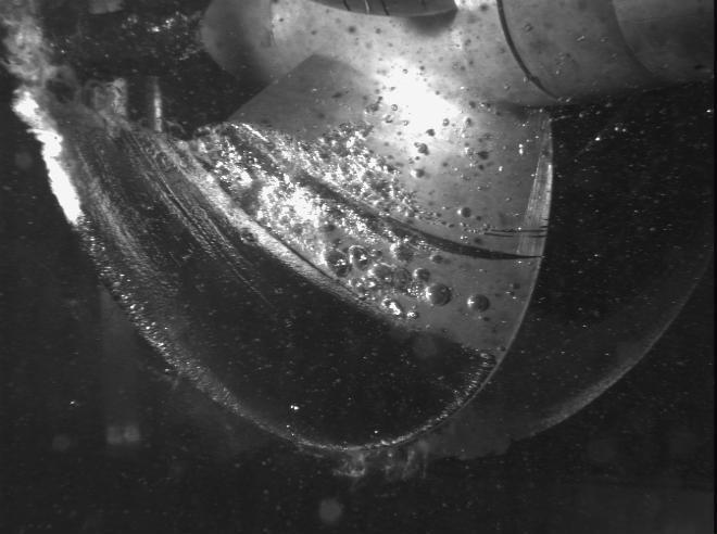
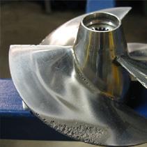
36 Cavitation Cavitation occurs when: local pressure < vapor pressure [13] [14] 36

37 Cavitation Cavitation can cause noise, vibration and damage [15] 37

38 Cavitation [16] 38
39 Cavitation [13] 39
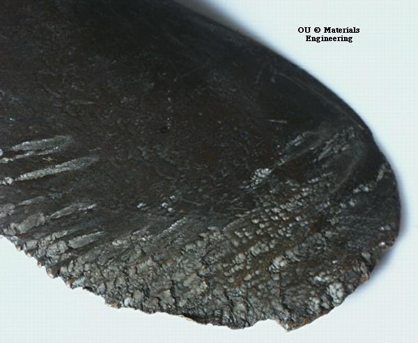

40 Cavitation [17] [18] 40
41 Design considerations Propellers Necessary thrust (dependent on resistance, hull design) skew Blade loading (dependent on thrust, blade area, pitch, strength) Space (dependent on hull design, design restrictions) Resonance frequency (dependent on structural design, number of blades, rotation rate) rake Cavitation Parameters: diameter, blade area, rotation rate, number of blades, blade shape (pitch, skew, rake) 41
![Sources images [1] Fixed Pitch propeller, source: unknown [2] Controllable pitch propeller, source: unknown [3] Kort Nozzle, source: Langemachinery Co.](/docs-images/79/80227495/images/42-0.jpg "Ltd [4] Four 250 ton Rolls-Royce Mermaid electric propulsion pods, source: unknown [5] The podded propulsion system on the ferry Nils Holgersson, source: ship-technology.")
![com [6] Helix Producer I propulsion system, source: ntd-offshore.com [7] Full rotating propeller, source: Hiroaki International (HK) Co., Ltd.](/docs-images/79/80227495/images/42-1.jpg "[8] Voith Schneider Propeller (VSP), source: Voith Turbo Pte Ltd., Singapore [9] Voith Turbo, source: heidenheim.voith.")
![com [10] Non-virtual Voith Schneider propeller, source: Voith Schneider [11] Kamewa waterjets employed by Rolls-Royce, source: Naval Technology [12] Hydrojet scheme 1- Ahead 2- Astern, source:](/docs-images/79/80227495/images/42-3.jpg "Tosaka/Wikimedia Commons [13] Source: unknown [14] Propeller Dynamometers, source: Cussons Marine [15] La cavitation, source: http://zone.sousmarins.free.fr/sous-marins%20et%20cavitation.")
42 Sources images [1] Fixed Pitch propeller, source: unknown [2] Controllable pitch propeller, source: unknown [3] Kort Nozzle, source: Langemachinery Co. Ltd [4] Four 250 ton Rolls-Royce Mermaid electric propulsion pods, source: unknown [5] The podded propulsion system on the ferry Nils Holgersson, source: ship-technology.com [6] Helix Producer I propulsion system, source: ntd-offshore.com [7] Full rotating propeller, source: Hiroaki International (HK) Co., Ltd. [8] Voith Schneider Propeller (VSP), source: Voith Turbo Pte Ltd., Singapore [9] Voith Turbo, source: heidenheim.voith.com [10] Non-virtual Voith Schneider propeller, source: Voith Schneider [11] Kamewa waterjets employed by Rolls-Royce, source: Naval Technology [12] Hydrojet scheme 1- Ahead 2- Astern, source: Tosaka/Wikimedia Commons [13] Source: unknown [14] Propeller Dynamometers, source: Cussons Marine [15] La cavitation, source: [16] Cavitating propeller in a water tunnel experiment at the David Taylor Model Basin, source: Wikimedia Commons [17] Cavitation damage evident on the propeller of a personal watercraft. Note the concentrated damage on the outer edge of the propeller where the speed of the blade is fastest, source: Axda0002/Wikimedia Commons [18] Cavitation, source: unknown 42
voith.com Precise and safe maneuvering Voith Schneider Propeller
 voith.com Precise and safe maneuvering Voith Schneider Propeller 5 Voith Schneider Propeller. Voith Turbo offers tailor-made propulsion systems for a wide variety of applications for harbor assistance
ENGR 4011 Resistance & Propulsion of Ships Assignment 5: A dimensional analysis of propeller thrust starting with the functional expression
 ENGR 40 Resistance & Propulsion of Ships ssignment 5: 07. -dimensional hydrofoil section is shown below. It has an incidence velocity V incidence at an angle of attack α E. For the case shown: sketch the
DYNAMIC POSITIONING CONFERENCE. October 13-14, Thrusters. Voith Schneider Propeller - An Efficient Propulsion System for DP Controlled Vessels
 Return to Session Directory DYNAMIC POSITIONING CONFERENCE October 13-14, 2009 Thrusters Voith Schneider Propeller - An Efficient Propulsion System for DP Controlled Vessels Dirk Jürgens, Michael Palm
ITTC Recommended Procedures and Guidelines Testing and Extrapolation Methods Propulsion, Performance Propulsion Test
 7.5- Page 1 of 13 Table of Contents... 2 1. PURPOSE OF PROCEDURE... 2 2. PARAMETERS... 2 2.1 Data Reduction Equations... 2 2.2 Definition of Variables... 3 3. DESCRIPTION OF PROCEDURE... 3 3.1 Model and
Teaching sessions week 40
 Teaching sessions week 40 Monday 28 September Lecture: Introduction to propulsion. Momentum theory of propeller action. Friday 2 October Lecture: Screw propeller Introduction of Marine Hydrodynamics 1
A Study on Effects of Blade Pitch on the Hydrodynamic Performances of a Propeller by Using CFD
 Journal of Shipping and Ocean Engineering 8 (2018) 36-42 doi 10.17265/2159-5879/2018.01.005 D DAVID PUBLISHING A Study on Effects of Blade Pitch on the Hydrodynamic Performances of a Propeller by Using
ENGR 4011 Resistance & Propulsion of Ships Assignment 4: 2017
 Question 1a. Values of forward speed, propeller thrust and torque measured during a propeller open water performance test are presented in the table below. The model propeller was 0.21 meters in diameter
Numerical Analysis of Unsteady Open Water Characteristics of Surface Piercing Propeller
 Third International Symposium on Marine Propulsors smp 13, Launceston, Tasmania, Australia, May 2013 Numerical Analysis of Unsteady Open Water Characteristics of Surface Piercing Propeller Kohei Himei
ITTC Recommended Procedures and Guidelines
 7.5 02 Page 1 of 21 Table of Contents 1 PURPOSE... 2 2 ITTC DICTIONARY OF SHIP HYDRODYNAMICS PROPELLER SECTION... 2 COMMENTS OF THE PROPULSION COMMITTEE OF 22 nd ITTC Several of the symbols and definitions
Rotor reference axis
 Rotor reference axis So far we have used the same reference axis: Z aligned with the rotor shaft Y perpendicular to Z and along the blade (in the rotor plane). X in the rotor plane and perpendicular do
Potsdam Propeller Test Case (PPTC) Test Case Description
 Test Case Description") Second International Symposium on Marine Propulsors smp 11, Hamburg, Germany, June 2011 Workshop: Propeller performance Potsdam Propeller Test Case (PPTC) Test Case Description Ulf Barkmann 1, Hans-Jürgen
Second International Symposium on Marine Propulsors smp 11, Hamburg, Germany, June 2011 Workshop: Propeller performance Potsdam Propeller Test Case (PPTC) Test Case Description Ulf Barkmann 1, Hans-Jürgen
DP MAINTENANCE TRAINING
 DP MAINTENANCE TRAINING SINGAPORE Topics Day 2 Review Introduction to Serial Communications Serial Interface Cards Using the Workstation Diagnostics Screens Practical Applications Discussion of AMC Topics
Drag and Torque on Locked Screw Propeller
 http://www.transnav.eu the International Journal on Marine Navigation and Safety of Sea Transportation Volume 8 Number 3 September 24 DOI:.276/.8.3.6 Drag and Torque on Locked Screw Propeller T. Tabaczek
Cavitation of a Propeller and Influence of a Wake Equalizing Duct
 http://www.transnav.eu the International Journal on Marine Navigation and Safety of Sea Transportation Volume 9 Number 2 June 2015 DOI: 10.12716/1001.09.02.11 Cavitation of a Propeller and Influence of
Thrusters. Numerical Analysis of Flow Around a Thruster
 Thrusters Numerical Analysis of Flow Around a Thruster Norbert W. H. Bulten Wärtsilä Propulson, Netherlands October 17-18, 2006 Return to Session Directory Numerical Analysis of Flow around a Thruster
ITTC Recommended Procedures and Guidelines
 Page 1 of 9 CONTENTS Model Test Experiments... 2 1. PURPOSE OF PROCEDURE... 2 2. PARAMETERS... 2 2.1 Model Parameters... 3 2.2 Environmental Parameters... 3 2.3 Operation of Thrusters... 3 2.3.1 Thruster-Current
Flexible Elliptic Oscillating Duct. Taking the FOD one step further.
 Third International Symposium on Marine Propulsors smp 13, Launceston, Tasmania, Australia, May 213 Flexible Elliptic Oscillating Duct. Taking the FOD one step further. Gerasimos Politis 1,Theodoros Ioannou
On the advanced extrapolation method for a new type of podded propulsor via CFD simulations and model measurements
 Fifth International Symposium on Marine Propulsors smp 17, Espoo, Finland, June 2017 On the advanced extrapolation method for a new type of podded propulsor via CFD simulations and model measurements Tomi
Machinery Requirements for Polar Class Ships
 (August 2006) (Rev.1 Jan 2007) (Corr.1 Oct 2007) Machinery Requirements for Polar Class Ships.1 Application * The contents of this Chapter apply to main propulsion, steering gear, emergency and essential
Full scale thruster performance and load determination based on numerical simulations
 Third International Symposium on Marine Propulsors smp 13, Launceston, Tasmania, Australia, May 213 Full thruster performance and load determination based on numerical simulations Norbert Bulten 1, Rik
Numerical Investigation of the Performance of Voith Schneider Propulsion
 American Journal of Marine Science, 214, Vol. 2, No. 3, 58-62 Available online at http://pubs.sciepub.com/marine/2/3/3 Science and Education Publishing DOI:12691/marine-2-3-3 Numerical Investigation of
DUAL-MODE CONTRAPROPELLER WITH CURVE STACKING LINE FOR BLADE
 Anatolij-Branko R. Togunjac, Ph.D, Research and Design Institute for Fishing Fleet, GIPRORYBFLOT, M. Morskaya str.,18-20, St. Petersburg, 190000 Russia Leonid I. Vishnevsky, D.Sc,Krylov Shipbuilding Research
A New Implementation of Vortex Lattice Method Applied to the Hydrodynamic Performance of the Propeller-Rudder
 A New Implementation of Vortex Lattice Method Applied to the Hydrodynamic Performance of the Propeller-Rudder Hassan Ghassemi, a,* and Farzam Allafchi, a a ) Department of Ocean Engineering, Amirkabir
Prediction of Propeller Performance Using Quasi-Continuous Method
 Prediction of Propeller Performance Using Quasi-Continuous Method Hao Rui, a,* and Jaswar Koto, b a) Aeronautics, Automotive and Ocean Engineering, Universiti Teknologi Malaysia, Malaysia b) Ocean and
Performance Assessment of the Waterjet Propulsion System through a Combined Analytical and Numerical Approach
 International Journal of Physics, 013, Vol. 1, No., -7 Available online at http://pubs.sciepub.com/ijp/1//1 Science and Education Publishing DOI:10.1691/ijp-1--1 Performance Assessment of the Waterjet
Measurement of speed loss due to waves
 Third International Symposium on Marine Propulsors smp 13, Launceston, Tasmania, Australia, May 213 Measurement of speed loss due to waves Sverre Steen 1 and Zhenju Chuang 1 1 Department of Marine Technology,
Analysis of Crashback Forces Compared with Experimental Results
 First International Symposium on Marine Propulsors SMP 09, Trondheim, Norway, une 2009 Analysis of Crashback Forces Compared with Experimental Results Scott Black and Susan Swithenbank Naval Surface Warfare
A NEW WAY OF SIMULATING WHALE TAIL PROPULSION
 A NEW WAY OF SIMULATING WHALE TAIL PROPULSION Written by: J.D. van Manen (Whale Tail Development, The Netherlands) and T. van Terwisga (MARIN, The Netherlands) Presented on 34 th WEGEMT School by: M.X.
Resistance and Propulsion
 MSc. Naval Architecture and Marine Engineering Resistance and Propulsion 0-0 Project Propeller Design with the Lifting Line Theory - Program PROPINFAC Resistance and Propulsion Project Propeller Design
6.1 Summary of Postgraduate Courses
 Chapter 6 Postgraduate Courses 6.1 Summary of Postgraduate Courses Course No Subject Title Credit Hours Math 6903 Advanced Mathematics 3 NAME 6000 Thesis M.Sc.Engg.: 18 Ph.D.: 45 NAME 6002 Project M.Engg.:
Wake fraction and thrust deduction during ship astern manoeuvres
 Wake fraction and thrust deduction during ship astern manoeuvres J. Artyszuk Maritime University of Szczecin, Poland Abstract A relatively small amount of data concerning the behaviour of propulsion coefficients,
Yiran Su 1, Seungnam Kim 1, Weikang Du 1, Spyros A. Kinnas 2, Mikael Grekula 3, Jan Hallander 3, Da- Qing Li 3
 Fifth International Symposium on Marine Propulsion SMP 17, Espoo, Finland, June 2017 Prediction of the Propeller-induced Hull Pressure Fluctuation via a Potential-based Method: Study of the Rudder Effect
DESIGN OPTIMIZATION STUDY ON A CONTAINERSHIP PROPULSION SYSTEM
 DESIGN OPTIMIZATION STUDY ON A CONTAINERSHIP PROPULSION SYSTEM Brian Cuneo Thomas McKenney Morgan Parker ME 555 Final Report April 19, 2010 ABSTRACT This study develops an optimization algorithm to explore
A simplified method for calculating propeller thrust decrease for a ship sailing on a given shipping lane
 POLISH MARITIME RESEARCH 2(82) 2014 Vol 21; pp. 27-33 10.2478/pomr-2014-0015 A simplified method for calculating propeller thrust decrease for a ship sailing on a given shipping lane Katarzyna Zelazny,
IDENTIFICATION OF SHIP PROPELLER TORSIONAL VIBRATIONS
 Journal of KONES Powertrain and Transport, Vol., No. 015 IDENTIFICATION OF SHIP PROPELLER TORSIONAL VIBRATIONS Jan Rosłanowski Gdynia Maritime University, Faculty of Marine Engineering Morska Street 81-87,
WATERJET PROPULSION SYSEM FOR HIGH SPEED CRAFTS
 ARAB ACADEMY FOR SCIENCE, TECHNOLOGY AND MARITIME TRANSPORT COLLEGE OF ENGINEERING AND TECHNOLOGY WATERJET PROPULSION SYSEM FOR HIGH SPEED CRAFTS Thesis Submitted to The Marine Engineering Department In
Propeller theories. Blade element theory
 30 1 Propeller theories Blade element theory The blade elements are assumed to be made up of airfoil shapes of known lift, C l and drag, C d characteristics. In practice a large number of different airfoils
Deliverable D.6.1. Application of CFD tools to the development of a novel propulsion concept
 TRIple Energy Saving by Use of CRP, CLT and PODded Propulsion Grant Agreement Number: 265809 Call identifier: FP7-SST-2010-RTD-1 Theme SST.2010.1.1-2.: Energy efficiency of ships WP 1 Deliverable D.6.1
Numerical calculations of the hydrodynamic performance of the contra-rotating propeller (CRP) for high speed vehicle
 for high speed vehicle") POLISH MARITIME RESEARCH 2(78) 2013 Vol 20; pp. 13-20 10.2478/pomr-2013-0012 Numerical calculations of the hydrodynamic performance of the contra-rotating propeller (CRP) for high speed vehicle Hassan
POLISH MARITIME RESEARCH 2(78) 2013 Vol 20; pp. 13-20 10.2478/pomr-2013-0012 Numerical calculations of the hydrodynamic performance of the contra-rotating propeller (CRP) for high speed vehicle Hassan
Numerical and Experimental Characterization of a CP Propeller Unsteady Cavitation at Different Pitch Settings
 Second International Symposium on Marine Propulsors smp 11, Hamburg, Germany, June 211 Numerical and Experimental Characterization of a CP Propeller Unsteady Cavitation at Different Pitch Settings Daniele
Reliability assessment of ship powering performance extrapolations using Monte Carlo methods
 Third International Symposium on Marine Propulsors smp 13, Launceston, Tasmania, Australia, May 2013 Reliability assessment of ship powering performance extrapolations using Monte Carlo methods Iwan M.
ITTC Recommended Procedures and Guidelines Performance, Propulsion 1978 ITTC Performance Prediction Method
 I ecommended 1978 I erformance rediction ethod 7.5 0 age 1 of 9 008 evision able of ontents 1978 I erformance rediction ethod... 1. UOE OF OEUE.... EIION OF OEUE....1 Introduction.... efinition of the
Propeller Loads of Large Commercial Vessels at Crash Stop
 Second International Symposium on Marine Propulsors smp 11, Hamburg, Germany, June 2011 Propeller Loads of Large Commercial Vessels at Crash Stop J.W. Hur, H. Lee, B.J. Chang 1 1 Hyundai Heavy Industries,
Offshore Hydromechanics Module 1
 Offshore Hydromechanics Module 1 Dr. ir. Pepijn de Jong 4. Potential Flows part 2 Introduction Topics of Module 1 Problems of interest Chapter 1 Hydrostatics Chapter 2 Floating stability Chapter 2 Constant
MODELLING THE DYNAMICS OF SHIPS WITH DIFFERENT PROPULSION SYSTEMS FOR CONTROL PURPOSE
 POLISH MARITIME RESEARCH 1(89) 2016 Vol. 23; pp. 31-36 10.1515/pomr-2016-0005 MODELLING THE DYNAMICS OF SHIPS WITH DIFFERENT PROPULSION SYSTEMS FOR CONTROL PURPOSE Witold Gierusz, Assoc. Prof. Gdynia Maritime
Rate-Dependent Hydroelastic Response of Self-Adaptive Composite Propellers in Fully Wetted and Cavitating Flows
 Proceedings of the 7 th International Symposium on Cavitation CAV2009 Paper No. 60 August 17-22, 2009, Ann Arbor, Michigan, USA Rate-Dependent Hydroelastic Response of Self-Adaptive Composite Propellers
Aerodynamic Performance 1. Figure 1: Flowfield of a Wind Turbine and Actuator disc. Table 1: Properties of the actuator disk.
 Aerodynamic Performance 1 1 Momentum Theory Figure 1: Flowfield of a Wind Turbine and Actuator disc. Table 1: Properties of the actuator disk. 1. The flow is perfect fluid, steady, and incompressible.
Performance evaluation of composite marine propeller using L 8 orthogonal array
 Performance evaluation of composite marine propeller using L 8 orthogonal array S.Solomon Raj Dr.P.Ravinder Reddy 2. Assistant professor, department of mechanical engineering, chaitanya bharathi institute
The Calculations of Propeller Induced Velocity by RANS and Momentum Theory
 J. Marine Sci. Appl. (2012) 11: 164-168 DOI: 10.1007/s11804-012-1118-1 The Calculations of Propeller Induced Velocity by RANS and Momentum Theory Qiuxin Gao *, Wei Jin and Dracos Vassalos Department of
Prediction of induced vibrations for a passenger - car ferry
 IOP Conference Series: Materials Science and Engineering PAPER OPEN ACCESS Prediction of induced vibrations for a passenger - car ferry To cite this article: L Crudu et al 2016 IOP Conf. Ser.: Mater. Sci.
developed at "Dunarea de Jos" University of Galati Presented by: BENZOHRA Abdelmalek
 Master Thesis presented in partial fulfillment of the requirements for the double degree: Advanced Master in Naval Architecture conferred by University of Liege "Master of Sciences in Applied Mechanics,
Facilities: CHL (Computational Hydrodynamics Laboratory) in ECJ 8.502
 in ECJ 8.502") Ocean Engineering Group (OEG)/EWRE (August 28, 2018) Spyros A. Kinnas Professor and Director of OTRC s UT Office (Offshore Technology Research Center) Kinnas Home Page @SpyrosKinnas on twitter Research
Ocean Engineering Group (OEG)/EWRE (August 28, 2018) Spyros A. Kinnas Professor and Director of OTRC s UT Office (Offshore Technology Research Center) Kinnas Home Page @SpyrosKinnas on twitter Research
Study on Extrapolation Method for Self-Propulsion Test with Pre-Swirl Device *
 Fifth International Symposium on Marine Propulsion smp 17, Espoo, Finland, June 2017 Study on Extrapolation Method for Self-Propulsion Test with Pre-Swirl Device * Moon-Chan Kim 1, Yong-Jin Shin 1, Won-Joon
AEROSPACE ENGINEERING
 AEROSPACE ENGINEERING Subject Code: AE Course Structure Sections/Units Topics Section A Engineering Mathematics Topics (Core) 1 Linear Algebra 2 Calculus 3 Differential Equations 1 Fourier Series Topics
7.2 Ship Drive Train and Power
 7.2 Ship Drive Train and Power Ship Drive Train System EHP Engine Reduction Gear Bearing Seals Strut Screw THP BHP SHP DHP Ship Drive Train and Power EHP Engine Reduction Gear Bearing Seals Strut Screw
APPLICATION OF ENERGY SAVING FINS ON RUDDERS
 Proceedings of ASME 25 34th International Conference on Ocean, Offshore and Arctic Engineering OMAE 25 May 3 - June 5, 25, St. John s, Newfoundland, Canada OMAE25-4796 APPLICATION OF ENERGY SAVING FINS
ADVANCES IN FULL-SCALE WAKE-FIELD PREDICTIONS AND THE IMPLICATIONS FOR THE PROPELLER DESIGN
 ADVANCES IN FULL-SCALE WAKE-FIELD PREDICTIONS AND THE IMPLICATIONS FOR THE PROPELLER DESIGN Gert-Jan Zondervan*, Bram Starke Maritime Research Institute Netherlands PO Box 28, 67 AA Wageningen, The Netherlands
VIBRATION ANALYSIS IN SHIP STRUCTURES BY FINITE ELEMENT METHOD
 Proceedings of COBEM 2007 Copyright 2007 by ABCM 19th International Congress of Mechanical Engineering November 5-9, 2007, Brasília, DF VIBRATION ANALYSIS IN SHIP STRUCTURES BY FINITE ELEMENT METHOD Luiz
Numerical Investigation of the Impact of SES-Waterjet Interactions and Flow Non-uniformity on Pump Performance
 11 th International Conference on Fast Sea Transportation FAST 2011, Honolulu, Hawaii, USA, September 2011 Numerical Investigation of the Impact of SES-Waterjet Interactions and Flow Non-uniformity on
Performance Investigation of Ducted Aerodynamic Propulsors
 First International Symposium on Marine Propulsors Smp 9, Trondheim, Norway, June 29 Performance Investigation of Ducted Aerodynamic Propulsors Naipei P. Bi, Kevin R. Kimmel, David J. Haas Naval Surface
Hydro-Structure Analysis of Composite Marine Propeller under Pressure Hydrodynamic Loading
 American Journal of Mechanical Engineering, 2015, Vol. 3, No. 2, 41-46 Available online at http://pubs.sciepub.com/ajme/3/2/2 Science and Education Publishing DOI:10.12691/ajme-3-2-2 Hydro-Structure Analysis
Design and Analysis of the Floating Kuroshio Turbine Blades
 Design and Analysis of the Floating Kuroshio Turbine Blades Fang-Ling hiu #1, Sin-An Lai #2, hi-fang Lee *3, Yu-An Tzeng #4, hing-yeh Hsin #5 # Dept. of Systems Engineering and Naval Architecture, National
Experiments with Podded Propulsors in Static Azimuthing Conditions
 Experiments with Podded Propulsors in Static Azimuthing Conditions Islam M. F 1, Veitch B 1, Akinturk A 2, Bose N 3 and Liu P 2 1 Faculty of Engineering and Applied Science, Memorial University of Newfoundland
2.00AJ / 16.00AJ Exploring Sea, Space, & Earth: Fundamentals of Engineering Design Spring 2009
 MIT OpenCourseWare http://ocw.mit.edu 2.00AJ / 16.00AJ Exploring Sea, Space, & Earth: Fundamentals of Engineering Design Spring 2009 For information about citing these materials or our Terms of Use, visit:
Fundamentals of Airplane Flight Mechanics
 David G. Hull Fundamentals of Airplane Flight Mechanics With 125 Figures and 25 Tables y Springer Introduction to Airplane Flight Mechanics 1 1.1 Airframe Anatomy 2 1.2 Engine Anatomy 5 1.3 Equations of
DETERMINING OPTIMUM GEOMETRY FOR A BOW THRUSTER PROPELLER
 DEERMINING OPIMUM GEOMERY FOR A BOW HRUSER PROPELLER Y.H. OZDEMIR, S. BAYRAKAR,. YILMAZ, M.GUNER Yildiz echnical University, Dept. of Naval Architecture and Marine Engineering, 34349 Besiktas, Istanbul,
Analysis and Experiments for Contra-Rotating Propeller
 Analysis and Experiments for Contra-Rotating Propeller by Eyal Kravitz Bachelor of Science in Mechanical Engineering Tel-Aviv University, 2005 Submitted to the Department of Mechanical Engineering in Partial
Model-Ship Correlation Method in the Mitsubishi Experimental Tank
 Model-Ship Correlation Method in the Mitsubishi Experimental Tank By Kaname Taniguchi*, Member Summary The model-ship correlation method which is developed and used in the Mitsubishi Experimental Tank
Propeller Analysis Using RANS/BEM Coupling Accounting for Blade Blockage
 DRDC-RDDC-2015-N005 Fourth International Symposium on Marine Propulsors smp 15, Austin, Texas, USA, June 2015 Propeller Analysis Using RANS/BEM Coupling Accounting for Blade Blockage David Hally 1 1 Defence
Performance Characteristics of Static and Dynamic Azimuthing Podded Propulsor
 First International Symposium on Marine Propulsors smp 09, Trondheim, Norway, June 009 Performance Characteristics of Static and Dynamic Azimuthing Podded Propulsor Mohammed F. Islam 1, Ayhan Akinturk,
Student name: This is a closed book examination. You are allowed 1 sheet of 8.5 x 11 paper with notes.
 13.012 Marine Hydrodynamics for Ocean Engineers Fall 2004 Quiz #2 Student name: This is a closed book examination. You are allowed 1 sheet of 8.5 x 11 paper with notes. For the problems in Section A, fill
Ship Project A ASSIGNMENT ONE RAN XIAO & THEIR TOMAS
 2014 Ship Project A ASSIGNMENT ONE RAN XIAO 467643 & THEIR TOMAS 224051 Resistance estimation Methodology brief As our ship concept is in form of catamaran, it is not proper to simply introduce the method
Applied Fluid Mechanics
 Applied Fluid Mechanics 1. The Nature of Fluid and the Study of Fluid Mechanics 2. Viscosity of Fluid 3. Pressure Measurement 4. Forces Due to Static Fluid 5. Buoyancy and Stability 6. Flow of Fluid and
Study of the influence of the resonance changer on the longitudinal vibration of marine propulsion shafting system
 Study of the influence of the resonance changer on the longitudinal vibration of marine propulsion shafting system Zhengmin Li 1, Lin He 2, Hanguo Cui 3, Jiangyang He 4, Wei Xu 5 1, 2, 4, 5 Institute of
Chapter 4 Estimation of wing loading and thrust loading - 7 Lecture 15 Topics
 Chapter 4 Estimation of wing loading and thrust loading - 7 Lecture 15 Topics 4.12 Introductory remarks on choice of engine 4.13 Engines considered for airplane applications 4.14 Piston engine-propeller
ITTC Recommended Procedures and Guidelines
 Page of Table of Contents Waterjet Propulsion Test and Extrapolation... PURPOSE OF PROCEDURE.... PARAMETERS.... Nomenclature... 3. DESCRIPTION OF PROCEDURE... 3 3. Model and installation... 3 3.. Resistance
ITTC Recommended Procedures Testing and Extrapolation Methods Resistance Resistance Test
 -0- Page 1 of 11 CONTENTS 1. PURPOSE OF PROCEDURE. PARAMETERS.1 Data Reduction Equations. Definition of ariables 3. DESCRIPTION OF PROCEDURE 3.1 Model and Installation 3.1.1 Model 3.1. Test condition 3.1.3
Offshore Hydromechanics Module 1
 Offshore Hydromechanics Module 1 Dr. ir. Pepijn de Jong 1. Intro, Hydrostatics and Stability Introduction OE4630d1 Offshore Hydromechanics Module 1 dr.ir. Pepijn de Jong Assistant Prof. at Ship Hydromechanics
Lecture 4: Wind energy
 ES427: The Natural Environment and Engineering Global warming and renewable energy Lecture 4: Wind energy Philip Davies Room A322 philip.davies@warwick.ac.uk 1 Overview of topic Wind resources Origin of
Estimating Maneuvering and Seakeeping Characteristics with Neural Networks
 070131-071 1 Estimating Maneuvering and Seakeeping Characteristics with Neural Networks Paulo Triunfante Martins 1, Victor Lobo 2, Member, IEEE Maneuvering and seakeeping are two very important naval architecture
Influence of Flow Transition on Open and Ducted Propeller Characteristics
 Fourth International Symposium on Marine Propulsors smp 15, Austin, Texas, USA, June 2015 Influence of Flow Transition on Open and Ducted Propeller Characteristics Anirban Bhattacharyya 1, Jan Clemens
Motions and Resistance of a Ship in Regular Following Waves
 Reprinted: 01-11-2000 Revised: 03-10-2007 Website: www.shipmotions.nl Report 440, September 1976, Delft University of Technology, Ship Hydromechanics Laboratory, Mekelweg 2, 2628 CD Delft, The Netherlands.
Unsteady Analysis of a Horizontal Axis Marine Current Turbine in Yawed Inflow Conditions With a Panel Method
 First International Symposium on Marine Propulsors smp 09, Trondheim, Norway, June 2009 Unsteady Analysis of a Horizontal Axis Marine Current Turbine in Yawed Inflow Conditions With a J. Baltazar, J.A.C.
Marine Propulsors. Design Methodology for Subcavitating. Archief
 TECHNLSCBE UNIVERSITEIT Scheepshydromechanica Archief Mekelweg 2, 2628 CD Delft Te1:015-2786873/Fax:2781836 NATIONAL TECHNICAL UNIVERSITY OF ATHENS DEPARTMENT OF NAVAL ARCHITECTURE AND MARINE ENGINEERING
Investigation on the influence of scaling effects in propeller testing through the use of theoretical prediction codes
 Master of Science Thesis Investigation on the influence of scaling effects in propeller testing through the use of theoretical prediction codes Thomas De Leeuw... 2013 Delft University of Technology Dept.
Simulation-driven Design of a Rim Drive for an Autonomous Vehicle
 Fifth International Symposium on Marine Propulsors smp 17, Espoo, Finland, June 2017 Simulation-driven Design of a Rim Drive for an Autonomous Vehicle Heinrich Grümmer 1, Stefan Harries 2 and Andrés Cura
The Floating Kuroshio Turbine Blades Geometry Design with Consideration of the Structural Strength
 TEAM 2017, Sep. 25-28, 2017, Osaka, Japan The Floating Kuroshio Turbine Blades Geometry Design with onsideration of the Structural Strength Sin-An Lai 1, hing-yeh Hsin 2, hi-fang Lee 3, Tsung-Yueh Lin
Comparison of Thruster Axis Tilting versus Nozzle Tilting on the Propeller-Hull Interactions for a Drillship at DP-Conditions
 DYNAMIC POSITIONING CONFERENCE October 12-13, 2010 Thrusters Comparison of Thruster Axis Tilting versus Nozzle Tilting on the Propeller-Hull Interactions for a Drillship at DP-Conditions Michael Palm,
Propellers and Ducted Fans
 Propellers and Ducted Fans Session delivered by: Prof. Q. H. Nagpurwala 1 To help protect your privacy, PowerPoint prevented this external picture from being automatically downloaded. To download and display
/ m U) β - r dr/dt=(n β / C) β+ (N r /C) r [8+8] (c) Effective angle of attack. [4+6+6]
![/ m U) β - r dr/dt=(n β / C) β+ (N r /C) r [8+8] (c) Effective angle of attack. [4+6+6]](/thumbs/91/105418625.jpg "/ m U) β - r dr/dt=(n β / C) β+ (N r /C) r [8+8] (c) Effective angle of attack. [4+6+6]") Code No: R05322101 Set No. 1 1. (a) Explain the following terms with examples i. Stability ii. Equilibrium. (b) Comment upon the requirements of stability of a i. Military fighter aircraft ii. Commercial
Code No: R05322101 Set No. 1 1. (a) Explain the following terms with examples i. Stability ii. Equilibrium. (b) Comment upon the requirements of stability of a i. Military fighter aircraft ii. Commercial
Dimensions of propulsion shafts and their permissible torsional vibration stresses
 (Feb 2005) (orr.1 Mar 2012) (orr.2 Nov 2012) Dimensions of propulsion shafts and their permissible torsional vibration stresses.1 Scope This UR applies to propulsion shafts such as intermediate and propeller
Lecture-4. Flow Past Immersed Bodies
 Lecture-4 Flow Past Immersed Bodies Learning objectives After completing this lecture, you should be able to: Identify and discuss the features of external flow Explain the fundamental characteristics
An Extrapolation Method Suitable for Scaling of Propellers of any Design
 Fourth International Symposium on Marine Propulsors smp 5, Austin, Texas, USA, June 205 An Extrapolation Method Suitable for Scaling of Propellers of any Design Dr. Stephan Helma Stone Marine Propulsion
Resistance and Propulsion of Ships Technical University Delft Course MT512
 Resistance and Propulsion of Ships Technical University Delft Course MT512 Prof. Dr. Ir. G.Kuiperl January 3, 1994 Re-v w7. @L%-74K 1MARIN, Maritime Research Institute Netherlands, Wageningen, Technical
CFD Based Hull Hydrodynamic Forces for Simulation of Ship Manoeuvres
 International Journal on Marine avigation and Safety of Sea Transportation Volume 3 umber 1 March 9 Based Hull Hydrodynamic Forces for Simulation of Ship Manoeuvres T. Tabaczek, T. Gornicz & J. Kulczyk
Calculation of Wind Turbine Geometrical Angles Using Unsteady Blade Element Momentum (BEM)
") Proceedings Conference IGCRE 2014 16 Calculation of Wind Turbine Geometrical Angles Using Unsteady Blade Element Momentum (BEM) Adel Heydarabadipour, FarschadTorabi Abstract Converting wind kinetic energy
Proceedings Conference IGCRE 2014 16 Calculation of Wind Turbine Geometrical Angles Using Unsteady Blade Element Momentum (BEM) Adel Heydarabadipour, FarschadTorabi Abstract Converting wind kinetic energy
Transactions on the Built Environment vol 24, 1997 WIT Press, ISSN
 Comparison of model test with ship sea trial results for a given vessel series C.Behrendt & T.Kucharski Institute of Marine Plant Operation, Maritime University of Szczecin, 70-500 Szczecin, Poland Abstract
A numerical DP MODULE to help design and operation for projects including DP components
 DYNAMIC POSITIONING CONFERENCE November 15-16, 25 Control Systems I A numerical DP MODULE to help design and operation for projects including DP components C. Le Cunff PRINCIPIA (La Ciotat, France) Return
Generally, there exists an optimum tip-speed-ratio, λ that maximized C p. The exact λ depends on the individual wind turbine design
 Summary Chapter 6-End 1 Wind Turbine Control The control system on a wind turbine is designed to: 1. seek the highest efficiency of operation that maximizes the coefficient of power, C p, 2. ensure safe
Tasmania 7250, Australia. nd K t --- Shaft thrust coefficient by traditional propeller definition
 Third International Symposium on Marine Propulsors smp 13, Launceston, Tasmania, Australia, May 2013 Parametric Analysis of Horizontal Axis Tidal Turbine Hydrodynamics for Optimum Energy Generation Pengfei