7.2 Ship Drive Train and Power
|
|
|
- Shawn Lawson
- 5 years ago
- Views:
Transcription
1 7.2 Ship Drive Train and Power Ship Drive Train System EHP Engine Reduction Gear Bearing Seals Strut Screw THP BHP SHP DHP
2 Ship Drive Train and Power EHP Engine Reduction Gear Bearing Seals Strut Screw THP BHP SHP DHP Brake Horsepower (BHP) - Power output at the shaft coming out of the engine before the reduction gears
3 Ship Drive Train and Power EHP Engine Reduction Gear Bearing Seals Strut Screw THP BHP SHP DHP Shaft Horsepower (SHP) - Power output at the shaft coming out of the reduction gears
4 Ship Drive Train and Power EHP Engine Reduction Gear Bearing Seals Strut Screw THP BHP SHP DHP Delivered Horsepower (DHP) - Power delivered to the propeller - DHP=SHP losses in shafting, shaft bearings and seals
5 Ship Drive Train and Power EHP Engine Reduction Gear Bearing Seals Strut Screw THP BHP SHP DHP Thrust Horsepower (THP) - Power created by the screw/propeller - THP=DHP Propeller losses - THP is the end result of all HP losses along the drive train
6 Ship Drive Train and Power E/G BHP R/G SHP Shaft Bearing DHP THP EHP Prop. Hull Relative Magnitudes BHP > SHP > DHP > THP > EHP The reverse relationship can NEVER be true because there is ALWAYS some loss of power due to heat, friction, and sound
7 7.3 Effective Horsepower (EHP) The power required to move the ship hull at a given speed in the absence of propeller action EHP is not related to Power Train System EHP can be determined from the towing tank experiments at the various speeds of the model ship EHP of the model ship is converted into EHP of the full scale ship by Froude s Law. Towing Tank Measured EHP V Towing carriage
8 Effective Horsepower (EHP) Effective Horsepower, EHP (HP) Typical POWER EHP CURVE Curve of YP YARD PATROL CRAFT Ship Speed, Vs (Knots) The required EHP varies depending on the vessel s speed.
9 EHP Calculation Effective Horsepower (EHP) EHP(H P ) R T (lb) VS ft lb s H P ft s R T total hull 550 V speed of ship S resistance ft RT V S lb s 1Watts 1/550 H P lb s ft J s Watts : Power
10 The loss in HP along the drive train can be related in terms of Gear Efficiency 7.4 Propulsion Efficiency EFFICIENCY, or h h gear = SHP BHP Shaft Horsepower Brake Horsepower -Highlights the loss of horsepower from the engine to the shaft as a result of the reduction gears - SHP is always less than BHP
11 Propulsion Efficiency Shaft Transmission Efficiency h shaft = DHP SHP Delivered Horsepower Shaft Horsepower - The loss of horsepower from the reduction gears to the propeller due to the bearings and seals that support and seal the drive shaft - The loss of power is converted to heat and sound due to friction
12 Propulsion Efficiency Hull Efficiency H EHP THP - Hull efficiency changes due to hull-propeller interactions. - Well-designed ship : H 1 - Poorly-designed ship : 1 Well-designed (The loss of power will be a function of the hull design) Effective Horsepower Thrust Horsepower H Poorly-designed - Flow is not smooth. - THP is reduced. - High THP is needed to get designed speed.
13 Propulsion Efficiency Propeller Efficiency propeller THP DHP SHP EHP Screw THP DHP
14 Propulsion Efficiency Propulsive Efficiency (Coefficient (PC)) h P = EHP SHP Effective Horsepower Shaft Horsepower - Combines the losses due to the bearings, guides, and the propeller efficiency -Compares the output from the reduction gears to the required towing HP -Commonly ranges from 55-75% -Once h p is found, can try different power plants, gearing, and fuel efficiencies
15 Example: Through modeling of a ship s design, it is found that the towing horsepower required to maintain a speed of 20 knots is 23,500 HP. Assuming a propulsive efficiency of 68%, what is the expected required power output from the reduction gears (shaft horsepower)? Solution: h P = EHP SHP.68 = 23,500 HP SHP SHP = 23,500 HP /.68 SHP = 34,559 HP
16 Example Problem What are the various components, HPs, hs and common values for hs for the drawing below? _HP _HP _HP _HP _HP h gear =_HP/_HP (~ - %) h shaft =_HP/_HP (~ - %) h prop =_HP/_HP (~ - %) h H =_HP/_HP h P =PC=_HP/_HP (~ - %)
17 Example Answer What are the various components, HPs, hs and common values for hs for the drawing below? Prime Mover BHP Reduction SHP Shafting & DHP Propeller THP Hull EHP Gear Bearings h gear =SHP/BHP (~98-99%) h shaft =DHP/SHP (~97-98%) h prop =THP/DHP (~70-75%) h H =EHP/THP h P =PC=EHP/SHP (~55-75%)
18 7.5 Total Hull Resistance Total Hull Resistance (R T ) The force that the ship experiences opposite to the motion of the ship as it moves. EHP Calculation EHP(H P ) R T (lb) 550 VS ft lb s H P ft s R T V S total hull resistance speed of ship
19 Total Hull Resistance Coefficient of Total Hull Resistance - Non-dimensional value of total resistance C T R T 0.5 V 2 S C R V S T T S s Coefficient of Total hull Fluid density Speed of resistance ship lb s 4 ft 2 total hull resistance in calm water wetted surface area on the submerged hull lb ft s 2 ft 2 non - dimension
20 Total Hull Resistance Coefficient of Total Hull Resistance -Total Resistance of full scale ship can be determined using C,, S and T V S R T ( lb) 0.5SV C T 2 S C : determined by the model test T : available from water property table S : obtained from Curves of form V : Full scale ship speed S
21 Total Hull Resistance Relation of Total Resistance Coefficient and Speed TOTAL RESISTANCE CURVE YARD PATROL CRAFT Total Resistance, Rt (lb) Ship Speed, Vs (knots) R T C T V n S V 2 S n from 2 at low speed to 5 at high speed EHP V R V n S T S C V 2 S V n from 3 at low speed to 6 at high speed T S
22 7.6 Total Hull Resistance Resistance values, denoted by R, are dimensional values R T = Total hull resistance is the sum of all resistance R T = R AA + R W + R V Air Resistance Wave Making Resistance Viscous Resistance R AA = Resistance caused by calm air on the superstructure R W = Resistance due to waves caused by the ship - A function of beam to length ratio, displacement, hull shape & Froude number (ship length & speed) R V = Viscous resistance (frictional resistance of water) - A function of viscosity of water, speed, and wetted surface area of ship For pilots, this is subsonic, incompressible drag
23 Total Hull Resistance Total Resistance and Relative Magnitude of Components Hump Hollow Air Resistance Wave-making Speed (kts) Viscous - Low speed : Viscous R - Higher speed : Wave-making R - Hump (Hollow) : location is function of ship length and speed.
24 Components of Total Resistance Viscous Resistance - Resistance due to the viscous stresses that the fluid exerts on the hull. ( due to friction of the water against the surface of the ship) - Viscosity, ship s velocity, wetted surface area of ship generally affect the viscous resistance. Wave-Making Resistance - Resistance caused by waves generated by the motion of the ship - Wave-making resistance is affected by beam to length ratio, displacement, shape of hull, Froude number (ship length & speed) Air Resistance - Resistance caused by the flow of air over the ship with no wind present - Air resistance is affected by projected area, shape of the ship above the water line, wind velocity and direction - Typically 4 ~ 8 % of the total resistance
25 Components of Total Resistance Dimensionless Coefficients C T = Coefficient of total hull resistance C T = C V + C W C V = Coefficient of viscous resistance over the wetted area of the ship as it moves through the water - C F = Tangential component (skin resistance) - KC F = Normal component (viscous pressure drag) C W = Coefficient of wave-making resistance
26 Coefficient of Viscous Resistance (C V ) Viscous Flow around a ship Real ship : Turbulent flow exists near the bow. Model ship : Studs or sand strips are attached at the bow to create the turbulent flow.
27 Coefficient of Viscous Resistance (C V ) Coefficients of Viscous Resistance - Non-dimensional quantity of viscous resistance - It consists of tangential and normal components. CF=tangential (skin friction) component of viscous resistance KCF=normal (viscous pressure/form drag) component of viscous friction C V C tangential C normal CF KC F flow bow ship stern Tangential Component : C F - Tangential stress is parallel to ship s hull and causes a net force opposing the motion ; Skin Friction - It is assumed C F can be obtained from the experimental data of flat plate.
28 Coefficient of Viscous Resistance (C V ) Tangential C F (log R 2) R n Component 10 LV V n S R L S n 2 of C V Reynolds L pp (ft) ft ft C Ship Speed(ft/s) Kinematic Viscosity (ft F Number /s /s for Semi-empirical equation 2 /s) for fresh water salt water
29 Coefficient of Viscous Resistance (C V ) Boundary Layer Separation Resistance Viscous Pressure/Form Drag Laminar Flow Low Velocity/ High Pressure High Velocity/ Low Pressure Bernoulli s Equation: p/r+v²/2+gz=constant Low Velocity/ High Pressure Turbulent Flow Low Velocity/ High Pressure Boundary Layer Boundary Layer High Velocity/ Low Pressure Boundary Layer Separation Turbulent Wake
30 Coefficient of Viscous Resistance (C V ) Tangential Component: C F - Relation between viscous flow and Reynolds number Laminar flow : In laminar flow, the fluid flows in layers in an orderly fashion. The layers do not mix transversely but slide over one another. Turbulent flow : In turbulent flow, the flow is chaotic and mixed transversely. Flow over flat plate Laminar Flow Turbulent Flow R n about R n about 510
31 Coefficient of Viscous Resistance (C V ) Normal Component: KC F - Normal component causes a pressure distribution along the underwater hull form of ship - A high pressure is formed in the forward direction opposing the motion and a lower pressure is formed aft. - Normal component generates the eddy behind the hull. - It is affected by hull shape. Fuller shape ship has larger normal component than slender ship. large eddy small eddy Full ship Slender ship
32 Coefficient of Viscous Resistance (C V ) Normal Component: KC F - It is calculated by the product of Skin Friction with Form Factor. Normal C F K K Component 19 L( of C 3 (ft ) ft) B( ft) T ( K C Skin Friction Coeff. Form Factor v ft) F B( L( ft) ft) 2
33 Coefficient of Viscous Resistance (C V ) C V C tangential C normal CF K C F C F (log 2 10 Rn 2) K 19 L( 3 (ft ) ft) B( ft) T ( ft) B( L( ft) ft) 2 R R L V n n S LVS K= Form Factor Reynolds Number L pp (ft) Ship Speed(ft/s) Kinematic Viscosity (ft ft ft 2 2 /s /s 2 /s) for fresh water for salt water
34 Coefficient of Viscous Resistance (C V ) Reducing the Viscous Resistance Coeff. - Method : Increase L while keeping the submerged volume constant 1) Form Factor K Normal component KC F Slender hull is favorable. ( Slender hull form will create a smaller pressure difference between bow and stern.) 2) Reynolds No. Rn CF KC F
35 Froude Number F n The Froude Number (inertia force/gravity force) is another dimensionless value derived from model testing: Fn = V \/gl Also used, but not dimensionless, is the Speed-to-Length Ratio: Speed-to-Length Ratio = V \/L...Velocity is typically expressed in Knots (1 knot = 1.688ft/s)
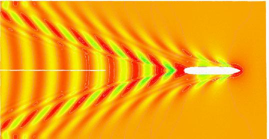
36 Coefficient of Wave Resistance C W Typical Wave Patterns are made up of TRANSVERSE and DIVERGENT waves Stern divergent wave Bow divergent wave Transverse wave L Wave Length
37 Coefficient of Wave Resistance CW
38 Coefficient of Wave Resistance C W Transverse wave System It travels at approximately the same speed as the ship. At slow speed, several crests exist along the ship length because the wave lengths are smaller than the ship length. As the ship speeds up, the length of the transverse wave increases. When the transverse wave length approaches the ship length, the wave making resistance increases very rapidly. This is the main reason for the dramatic increase in Total Resistance as speed increases.
39 Coefficient of Wave Resistance C W Transverse wave System Vs < Hull Speed Vs Hull Speed Wave Length Wave Length Slow Speed High Speed Hull Speed : speed at which the transverse wave length equals the ship length. (Wavemaking resistance drastically increases above hull speed)
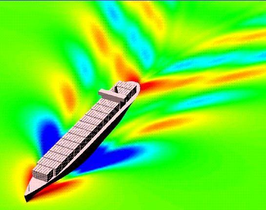
40 Coefficient of Wave Resistance C W Divergent Wave System It consists of Bow and Stern Waves. Interaction of the bow and stern waves create the Hollow or Hump on the resistance curve. Hump : When the bow and stern waves are in phase, the crests are added up so that larger divergent wave systems are generated. Hollow : When the bow and stern waves are out of phase, the crests matches the trough so that smaller divergent wave systems are generated.
41 Coefficient of Wave Resistance C W Hump Hollow Air Resistance Wave-making Speed (kts) Viscous - Low speed : Viscous R - Higher speed : Wave-making R - Hump (Hollow) : location is function of ship length and speed.
42 Coefficient of Wave Resistance C W Calculation of Wave-Making Resistance Coeff. Wave-making resistance is affected by - beam to length ratio - displacement - hull shape - Froude number The calculation of the coefficient is far difficult and inaccurate from any theoretical or empirical equation. (Because mathematical modeling of the flow around ship is very complex since there exists fluid-air boundary, wave-body interaction) Therefore model test in the towing tank and Froude expansion are needed to calculate the Cw of the real ship.
43 Coefficient of Wave Resistance C W It takes energy to produce waves, and as speed increases, the energy required is a square function of velocity! L wave = 2pV 2 g The limiting speed, or hull speed, can be found as: V = 1.34 \/L s Note: Remember at the hull speed, L wave and L s are approximately equal!
44 Coefficient of Wave Resistance C W Reducing Wave Making Resistance 1) Increasing ship length to reduce the transverse wave - Hull speed will increase. - Therefore increment of wave-making resistance of longer ship will be small until the ship reaches to the hull speed. - EX : FFG7 : ship length 408 ft hull speed 27 KTS CVN65 : ship length 1040 ft hull speed 43 KTS
45 Coefficient of Wave Resistance C W Reducing Wave Making Resistance 2) Attaching Bulbous Bow to reduce the bow divergent wave - Bulbous bow generates the second bow waves. - Then the waves interact with the bow wave resulting in ideally no waves, practically smaller bow divergent waves. - EX : DDG 51 : 7 % reduction in fuel consumption at cruise speed 3% reduction at max speed. design &retrofit cost : less than $30 million life cycle fuel cost saving for all the ship : $250 mil. Tankers & Containers : adopting the Bulbous bow


46 Bulbous Bow Coefficient of Wave Resistance C W
47 C C Coefficient of Total Resistance Coefficient of total hull resistance T V C C F ( 1 C A W : C A K) C W C Correlation Allowance A Correlation Allowance It accounts for hull resistance due to surface roughness, paint roughness, corrosion, and fouling of the hull surface. It is only used when a full-scale ship prediction of EHP is made from model test results. For model, C A 0 Since model surface is smooth. For ship, empirical formulas can be used.
48 Other Type of Resistances Appendage Resistance - Frictional resistance caused by the underwater appendages such as rudder, propeller shaft, bilge keels and struts - 224% of the total resistance in naval ship. Steering Resistance - Resistance caused by the rudder motion. - Small in warships but troublesome in sail boats Added Resistance - Resistance due to sea waves which will cause the ship motions (pitching, rolling, heaving, yawing).
49 Other Type of Resistances Increased Resistance in Shallow Water - Resistance caused by shallow water effect - Flow velocities under the hull increases in shallow water. Increase of frictional resistance due to the velocities Pressure drop, suction, increase of wetted surface area Increases frictional resistance - The waves created in shallow water take more energy from the ship than they do in deep water for the same speed. Increases wave making resistance
50 Operating to Minimize Resistance Keep the hull clean Operate at a prudent speed Keep speed below hump speed to optimize economy
51 7.7 Tow Tank Modeling So far we ve discussed what resistance is and how it can quantified using: - R T by measuring the actual resistance force - C T dimensionless coefficients that can be used to compare resistance between dissimilar hull shapes and sizes We can now measure the resistance in a hull and use the data to designing a ship s power plant - Using the resistance data, an effective power plant can be designed - Taking into account the relationship between - Effective Horsepower, EHP - Shaft Horsepower, SHP
52 Tow Tank Modeling Resistance and power are related! EHP = R t V s 550 ft - lb sec-hp Resistance can be measured in two ways: - Computer modeling - Can be very difficult to mathematically model viscous flow in 3 dimensions - Tow Tank testing - Producing a geometrically and dynamically similar model to test - Relate model performance to expected actual ship performance
53 Tow Tank Modeling Tow Tank testing is the obvious way to go! But to do so, your model ship must meet some criteria: 1. Geometric Similarity - The dimensions of the model and ship must be scaled exactly - The Scale Factor is called l (lambda) l = L S (ft) L M (ft) l 2 = S S (ft 2 ) S M (ft 2 ) l 3 = V S (ft 3 ) V M (ft 3 ) Length Area Volume where: M = Model S = Ship Note that a minor error in any length measurement will be cubed (n 3 )in volume scaling!
54 Tow Tank Modeling 2. Dynamic Similarity - Motion of the vessel must also be scaled, including: - Ship s velocity - Acceleration - Viscosity of the water - Dynamic similarity can only be approximated as water s viscosity and the forces of gravity can not be manipulated C W M = C W S C V M = C V S - The trade-off is a partial similarity - Froude s Law of Comparison or Law of Corresponding Speeds
55 Tow Tank Modeling The Law of Corresponding Speeds says: V S L S = V M L M
56 Tow Tank Modeling We ve already defined l as: l = L S (ft) L M (ft) If we wanted to solve for the scale speed for the model, V M = V S L M L S or V M = V S l -1/2...NOTE! 1 kt is equal to ft/sec! ALL velocities are done in feet/sec!
57 Example 1: The USS Monitor was 197 ft long and 40 ft across the beam and was able to maintain a maximum speed of 6 kts. You would like to create a model for testing that is 5 ft long. How wide should the model be? How fast should the model be towed to represent the actual ship s max speed? l = L S /L M l = 197 ft /5 ft l = 39.4 Solving for the width, l = W S /W M W M = 40 ft/39.4 W M = ft
58 Solving for the maximum speed, V S L S = V M L M V M = V S l -1/2 V M = 6 kts (1.688 ft/sec-kts) x /2 V M = ft/s x.1593 V M = ft/s
59 Example 2: The Yard Patrol (YP) is 110 ft long. It has a top speed of 13 kts on a good day. It displaces 150 LT. How long must a 1:25 scale model be? How fast must it be towed to simulate the top speed? l = 25 (the scale is given!) 25 = L S /L M L M = 110ft/25 L M 4.4 ft (52.8 in)
60 Solving for the maximum speed, V S L S = V M L M V M = V S l -1/2 V M = 13 kts (1.688 ft/sec-kts) x 25-1/2 V M = ft/s x.0.20 V M = 4.39 ft/s
61 Example Problem You are the chief Naval Architect assigned to design a new YP for the Naval Academy. You have already decided on a displacement, hull size and shape. You now need to use tow tank testing of a model to determine the engine size and fuel capacity required. Ship Data: D=300LT Length=100ft Beam=25ft Draft=6ft Wetted Surface Area=3225ft² Desired Max Speed=15kts
62 Example Problem The maximum length of model which the tow tank can handle is 5ft. If the model is constructed of this length, to maintain geometric similarity, what would be its beam? Maintaining geometric similarity, what is the wetted surface area of the model? Maintaining geometric similarity, what is the displacement of the model in pounds? (Assume tow tank is seawater.) Maintaining dynamic similarity, at what speed in ft/s do we need to tow the model? At this speed, the model resistance is 6.58lb. Coefficient of Viscous Resistance (model)(c v )= What is the wave making coefficient (C w )? At 15kts, C v for the ship is What is the resistance for the full size ship at this speed? What is the EHP at this speed and, if we expect h p =55%, how many SHP are required?
63 Example Answer Scale Factor =l=l s /L m =100ft/5ft=20; B m =B s /l=25ft/20=1.25ft A m =A s /l²=3225ft²/20²=8.06ft² D=F B =rgv Thus, it is proportional to submerged volume which is proportional to l³; D m =D s /l³=300lt (2240lb/LT)/20³=84lbs Law of Corresponding Speeds: v m =v s /l ½ =15kts (1.688ft/s-kt)/20 ½ =5.7ft/s C T =R T /(½rSV²)=6.58lb/[½ 1.99lbs²/ft ft² (5.7ft/s)²]=0.0253; C w =C T -C v = = C ws =C wm ; C T =C v +C w = = R T =C T ½rSV²= ½ (1.99lbs²/ft 4 ) 3225ft² (15kt 1.688ft/s-kt)²=45,100lb EHP=R T V/(550ft-lb/s-HP)=45,100lb 15kt 1.688ft/skt/(550ft-lb/s-HP)=2076HP; SHP=EHP/h p =2076/0.55=3775HP
64 7.8 Screw Propellers BLADE TIP TIP CIRCLE ROOT HUB PROPELLER DISC SUCTION BACK PRESSURE FACE ROTATION TRAILING EDGE LEADING EDGE
65 Screw Propellers Definitions Diameter(D) : distance from tip to tip Hub : the connection between propeller and shaft Blade Tip : the furthest point on the blade Blade Root : the point where the blade meets the hub Pitch(P) : Theoretical distance a propeller would move in one revolution Pitch Angle : Angle of the blade with respect to incoming flow. It usually varies from root to tip. Fixed Pitch : - The pitch is constant all the way from the blade root to the blade tip. - Blade is fixed to the hub and cannot be altered. Tip Circle : Circle described by the blade tip rotation Propeller Disc : The area circumscribed by the propeller s tip circle
66 Propeller Pitch Screw Propellers The distance that the blade travels in one revolution, P - measured in feet pitch Hub
67 Propeller Pitch Angle Screw Propellers The pitch angle relates the pitch length to the circumference of the propeller blade: tan f = P 2pr Pitch angle f is the angle that any part of the blade makes perpendicular with the water flow
68 Screw Propellers Types of Propeller Pitch 1. Constant Pitch- The pitch angle does not change, it is the same at the root as at the tip of the blade, but the pitch will vary or the pitch does not change, but the pitch angle does change. 2. Variable Pitch- The pitch angle changes as the distance from the root changes (f is defined at a blade radius of.7r) 3. Fixed Pitch- The blade is permanently attached to the hub and cannot change. 4. Controllable Pitch- The position of the blade can be altered while the blade rotates, thereby changing the pitch angle.
69 Screw Propellers Definitions Pressure face : - High pressure side of blade. The astern side when going ahead Suction Back : Low pressure side. Surface opposite the face Leading edge : Forward edge of the blade, first to encounter the water stream Trailing edge : Last part of the blade to encounter the water stream Suction side T.E. Pressure side L.E.
70 Screw Propellers
71 Screw Propellers Propeller Action Forward Resistance to Propeller Rotation Reaction Force on Propeller Propeller Rotation Propeller Thrust Relative Motion of Water Flow Suction Back Pitch Angle High Pressure Face

72 Propeller Rotation Screw Propellers Left hand screw - Rotates Counter Clock-wise when viewed from astern - Single screw ships use this type Right hand screw - Rotates Clock-wise when viewed from astern Naval Ship Counter Rotating Propellers - Have both a right and left hand screw - Eliminates torque created by the rotation - Torque will cause the stern to make a turn in the direction of rotation Submarines & torpedoes

73 Screw Propellers The Skewed Propeller Highly Skewed Propeller for a DDG 51 Advantages: - Reduced interaction between propeller and rudder wake - Reduced vibration and noise Disadvantages: - Expensive - Less efficient operating in reverse
74 Screw Propellers Propeller Theory Speed of Advance P Q V water VS 0 Vwater V S V Wake Region The ship drags the surrounding water. This wake follows the ship with a wake speed (Vw). The flow speed at the propeller is, W V A V S V W Speed of Advance
75 Screw Propellers Propeller Efficiency Propeller Theory propeller 1 T CT 2 0.5VA A 2 1 C o t C T : Thrust loading coefficient T : Propeller thrust A o : Area of propeller THP DHP (~70 % for well-designed PP.) the projected propeller disc - For a given T (Thrust), Ao (i.e., Diameter ) ; CT ; Prop Eff. Maximum The larger the diameter of propeller, the better the propeller efficiency
76 Screw Propellers Propellers generate thrust as soon as they rotate, even before the ship starts moving K T =T/(rn²D 4 ) K T =thrust coefficent r=water density n=shaft RPM D=propeller diameter
77 Screw Propellers Propeller Cavitation - The formation and collapse of vapor bubbles on propeller blades where the pressure has fallen below the vapor pressure of water Cavitation occurs on propellers that are heavily loaded, or are experiencing a high thrust loading coefficient
78 Screw Propellers Cavitation Process Pressure (atm) 1.0 Pv LIQUID A C Vaporization Line B VAPOR ( A to C cavitation) ( A to B boiling water) Temperature ( C) Vapor pressure 15 C 0.25 psi 100 C 14.7psi=1atm =101 kpa
79 Screw Propellers


80 Screw Propellers Blade Tip Cavitation Navy Model Propeller 5236 Flow velocities at the tip are fastest so that pressure drop occurs at the tip first. Sheet Cavitation Large and stable region of cavitation covering the suction face of propeller.
81 Screw Propellers Consequences of Cavitation 1) Low propeller efficiency (Thrust reduction) 2) Propeller erosion (Mechanical erosion) (Severe damage to propeller : up to 180 ton/in²) 3) Vibration due to uneven loading 4) Cavitation noise due to impulsion by the bubble collapse
82 Screw Propellers Preventing Cavitation - Remove fouling, nicks and scratch. - Increase or decrease the engine RPM smoothly to avoid an abrupt change in thrust. rapid change of rpm high propeller thrust but small change in VA larger CT cavitation & low propeller efficiency - Keep appropriate pitch setting for controllable pitch propeller - For submarines, diving to deeper depths will delay or prevent cavitation as hydrostatic pressure increases.
83 Screw Propellers Ventilation - If a propeller operates too close to the water surface, surface air or exhaust gases are drawn into the propeller blade due to the localized low pressure around propeller. - The load on the propeller is reduced by the mixing of air or exhaust gases into the water causing effects similar to those for cavitation. -Ventilation often occurs in ships in a very light condition(small draft) and in rough seas.
84 Example Problem: Name the parts of a propellers: Direction of Rotation R Forward
85 Example Answer: Name the parts of a propellers: Propeller Radius (R) Hub Blade Tip Blade Root Tip Circle Propeller Disc Leading Edge Trailing Edge Pressure Face Suction Back Direction of Rotation R Forward
MEC-E2001 Ship Hydrodynamics. Prof. Z. Zong Room 213a, K3, Puumiehenkuja 5A, Espoo
 MEC-E2001 Ship Hydrodynamics Prof. Z. Zong zhi.zong@aalto.fi Room 213a, K3, Puumiehenkuja 5A, 02510 Espoo Teacher: Prof. Z. Zong, zhi.zong@aalto.fi Room 213a, K3, Puumiehenkuja 5A, 02510 Espoo Teaching
Model-Ship Correlation Method in the Mitsubishi Experimental Tank
 Model-Ship Correlation Method in the Mitsubishi Experimental Tank By Kaname Taniguchi*, Member Summary The model-ship correlation method which is developed and used in the Mitsubishi Experimental Tank
ENGR 4011 Resistance & Propulsion of Ships Assignment 4: 2017
 Question 1a. Values of forward speed, propeller thrust and torque measured during a propeller open water performance test are presented in the table below. The model propeller was 0.21 meters in diameter
Offshore Hydromechanics Module 1
 Offshore Hydromechanics Module 1 Dr. ir. Pepijn de Jong 6. Real Flows part 2 Introduction Topics of Module 1 Problems of interest Chapter 1 Hydrostatics Chapter 2 Floating stability Chapter 2 Constant
Applied Fluid Mechanics
 Applied Fluid Mechanics 1. The Nature of Fluid and the Study of Fluid Mechanics 2. Viscosity of Fluid 3. Pressure Measurement 4. Forces Due to Static Fluid 5. Buoyancy and Stability 6. Flow of Fluid and
DESIGN OPTIMIZATION STUDY ON A CONTAINERSHIP PROPULSION SYSTEM
 DESIGN OPTIMIZATION STUDY ON A CONTAINERSHIP PROPULSION SYSTEM Brian Cuneo Thomas McKenney Morgan Parker ME 555 Final Report April 19, 2010 ABSTRACT This study develops an optimization algorithm to explore
Chapter 7 DIMENSIONAL ANALYSIS AND SIMILITUDE Because so few real flows can be solved exactly by analytical methods alone, the development of fluid
 Chapter 7 DIMENSIONAL ANALYSIS AND SIMILITUDE Because so few real flows can be solved exactly by analytical methods alone, the development of fluid mechanics has depended heavily on experimental results.
ITTC Recommended Procedures and Guidelines Testing and Extrapolation Methods Propulsion, Performance Propulsion Test
 7.5- Page 1 of 13 Table of Contents... 2 1. PURPOSE OF PROCEDURE... 2 2. PARAMETERS... 2 2.1 Data Reduction Equations... 2 2.2 Definition of Variables... 3 3. DESCRIPTION OF PROCEDURE... 3 3.1 Model and
Numerical Analysis of Unsteady Open Water Characteristics of Surface Piercing Propeller
 Third International Symposium on Marine Propulsors smp 13, Launceston, Tasmania, Australia, May 2013 Numerical Analysis of Unsteady Open Water Characteristics of Surface Piercing Propeller Kohei Himei
Ship Resistance And Propulsion Prof. Dr. P. Krishnankutty Ocean Department Indian Institute of Technology, Madras
 Ship Resistance And Propulsion Prof. Dr. P. Krishnankutty Ocean Department Indian Institute of Technology, Madras Lecture - 14 Ship Resistance Prediction Methods II We have been discussing about resistance
ESTIMATION OF HULL S RESISTANCE AT PRELIMINARY PHASE OF DESIGNING
 Journal of KONES Powertrain and Transport, Vol. 24, No. 1 2017 ESTIMATION OF HULL S RESISTANCE AT PRELIMINARY PHASE OF DESIGNING Adam Charchalis Gdynia Maritime University, Faculty of Marine Engineering
ITTC Recommended Procedures Testing and Extrapolation Methods Resistance Resistance Test
 -0- Page 1 of 11 CONTENTS 1. PURPOSE OF PROCEDURE. PARAMETERS.1 Data Reduction Equations. Definition of ariables 3. DESCRIPTION OF PROCEDURE 3.1 Model and Installation 3.1.1 Model 3.1. Test condition 3.1.3
VIBRATION ANALYSIS IN SHIP STRUCTURES BY FINITE ELEMENT METHOD
 Proceedings of COBEM 2007 Copyright 2007 by ABCM 19th International Congress of Mechanical Engineering November 5-9, 2007, Brasília, DF VIBRATION ANALYSIS IN SHIP STRUCTURES BY FINITE ELEMENT METHOD Luiz
BOUNDARY LAYER FLOWS HINCHEY
 BOUNDARY LAYER FLOWS HINCHEY BOUNDARY LAYER PHENOMENA When a body moves through a viscous fluid, the fluid at its surface moves with it. It does not slip over the surface. When a body moves at high speed,
Deliverable D.6.1. Application of CFD tools to the development of a novel propulsion concept
 TRIple Energy Saving by Use of CRP, CLT and PODded Propulsion Grant Agreement Number: 265809 Call identifier: FP7-SST-2010-RTD-1 Theme SST.2010.1.1-2.: Energy efficiency of ships WP 1 Deliverable D.6.1
Transactions on the Built Environment vol 24, 1997 WIT Press, ISSN
 Comparison of model test with ship sea trial results for a given vessel series C.Behrendt & T.Kucharski Institute of Marine Plant Operation, Maritime University of Szczecin, 70-500 Szczecin, Poland Abstract
6.1 Propellor e ciency
 Chapter 6 The Turboprop cycle 6. Propellor e ciency The turboprop cycle can be regarded as a very high bypass limit of a turbofan. Recall that the propulsive e ciency of a thruster with P e = P 0 and f
Basic Information to Help Select the Correct Propeller
 Propeller Performance Factors - Basic Information to Help Select the Correct Propeller The performance of a propeller in flight involves several complex subjects, and the high performance propellers we
Recap: Static Fluids
 Recap: Static Fluids Archimedes principal states that the buoyant force acting on an object is equal to the weight of fluid displaced. If the average density of object is greater than density of fluid
MECHANICAL PROPERTIES OF FLUIDS:
 Important Definitions: MECHANICAL PROPERTIES OF FLUIDS: Fluid: A substance that can flow is called Fluid Both liquids and gases are fluids Pressure: The normal force acting per unit area of a surface is
Study of the hydrodynamic flow around a 70m sailing boat for powering, wave pattern and propeller efficiency prediction
 Study of the hydrodynamic flow around a 70m sailing boat for powering, wave pattern and propeller efficiency prediction Romain Baudson Supervisor: Prof. Dario Boote (UNIGE) External Reviewer: Prof. Pierre
ADVANCES IN FULL-SCALE WAKE-FIELD PREDICTIONS AND THE IMPLICATIONS FOR THE PROPELLER DESIGN
 ADVANCES IN FULL-SCALE WAKE-FIELD PREDICTIONS AND THE IMPLICATIONS FOR THE PROPELLER DESIGN Gert-Jan Zondervan*, Bram Starke Maritime Research Institute Netherlands PO Box 28, 67 AA Wageningen, The Netherlands
Potsdam Propeller Test Case (PPTC) Test Case Description
 Test Case Description") Second International Symposium on Marine Propulsors smp 11, Hamburg, Germany, June 2011 Workshop: Propeller performance Potsdam Propeller Test Case (PPTC) Test Case Description Ulf Barkmann 1, Hans-Jürgen
Second International Symposium on Marine Propulsors smp 11, Hamburg, Germany, June 2011 Workshop: Propeller performance Potsdam Propeller Test Case (PPTC) Test Case Description Ulf Barkmann 1, Hans-Jürgen
CHAPTER EIGHT P U M P I N G O F L I Q U I D S
 CHAPTER EIGHT P U M P I N G O F L I Q U I D S Pupmps are devices for supplying energy or head to a flowing liquid in order to overcome head losses due to friction and also if necessary, to raise liquid
Fluid Mechanics Prof. T.I. Eldho Department of Civil Engineering Indian Institute of Technology, Bombay. Lecture - 17 Laminar and Turbulent flows
 Fluid Mechanics Prof. T.I. Eldho Department of Civil Engineering Indian Institute of Technology, Bombay Lecture - 17 Laminar and Turbulent flows Welcome back to the video course on fluid mechanics. In
Part A: 1 pts each, 10 pts total, no partial credit.
 Part A: 1 pts each, 10 pts total, no partial credit. 1) (Correct: 1 pt/ Wrong: -3 pts). The sum of static, dynamic, and hydrostatic pressures is constant when flow is steady, irrotational, incompressible,
Machinery Requirements for Polar Class Ships
 (August 2006) (Rev.1 Jan 2007) (Corr.1 Oct 2007) Machinery Requirements for Polar Class Ships.1 Application * The contents of this Chapter apply to main propulsion, steering gear, emergency and essential
Welcome to the Ship Resistance Predictor! The total calm water resistance is given by:
 Welcome to the Ship Resistance Predictor! What does this Excel Sheet do? This Excel sheet helps you calculate the Total Calm Water Resistance for a Ship at a given forward speed It also calculates from
ν δ - 1 -
 ν δ - 1 - δ ν ν δ ν ν - 2 - ρ δ ρ θ θ θ δ τ ρ θ δ δ θ δ δ δ δ τ μ δ μ δ ν δ δ δ - 3 - τ ρ δ ρ δ ρ δ δ δ δ δ δ δ δ δ δ δ - 4 - ρ μ ρ μ ρ ρ μ μ ρ - 5 - ρ τ μ τ μ ρ δ δ δ - 6 - τ ρ μ τ ρ μ ρ δ θ θ δ θ - 7
voith.com Precise and safe maneuvering Voith Schneider Propeller
 voith.com Precise and safe maneuvering Voith Schneider Propeller 5 Voith Schneider Propeller. Voith Turbo offers tailor-made propulsion systems for a wide variety of applications for harbor assistance
(3) BIOMECHANICS of LOCOMOTION through FLUIDS
 BIOMECHANICS of LOCOMOTION through FLUIDS") (3) BIOMECHANICS of LOCOMOTION through FLUIDS Questions: - Explain the biomechanics of different modes of locomotion through fluids (undulation, rowing, hydrofoils, jet propulsion). - How does size influence
(3) BIOMECHANICS of LOCOMOTION through FLUIDS Questions: - Explain the biomechanics of different modes of locomotion through fluids (undulation, rowing, hydrofoils, jet propulsion). - How does size influence
Contents. 2 Basic Components Aerofoils Force Generation Performance Parameters xvii
 Contents 1 Working Principles... 1 1.1 Definition of a Turbomachine... 1 1.2 Examples of Axial Turbomachines... 2 1.2.1 Axial Hydraulic Turbine... 2 1.2.2 Axial Pump... 4 1.3 Mean Line Analysis... 5 1.4
CHAPTER 9 DIMENSIONAL ANALYSIS AND SCALING
 CHAPTER 9 DIMENSIONAL ANALYSIS AND SCALING The Philosopher s approach The Mathematicians s approach The Engineer s approach Example - an orifice plate Example - an aeroplane Example - the drag force on
Performance Assessment of the Waterjet Propulsion System through a Combined Analytical and Numerical Approach
 International Journal of Physics, 013, Vol. 1, No., -7 Available online at http://pubs.sciepub.com/ijp/1//1 Science and Education Publishing DOI:10.1691/ijp-1--1 Performance Assessment of the Waterjet
Fluid Mechanics Prof. T. I. Eldho Department of Civil Engineering Indian Institute of Technology, Bombay
 Fluid Mechanics Prof. T. I. Eldho Department of Civil Engineering Indian Institute of Technology, Bombay Lecture No. # 35 Boundary Layer Theory and Applications Welcome back to the video course on fluid
Propeller Loads of Large Commercial Vessels at Crash Stop
 Second International Symposium on Marine Propulsors smp 11, Hamburg, Germany, June 2011 Propeller Loads of Large Commercial Vessels at Crash Stop J.W. Hur, H. Lee, B.J. Chang 1 1 Hyundai Heavy Industries,
Lecture-4. Flow Past Immersed Bodies
 Lecture-4 Flow Past Immersed Bodies Learning objectives After completing this lecture, you should be able to: Identify and discuss the features of external flow Explain the fundamental characteristics
Bluff Body, Viscous Flow Characteristics ( Immersed Bodies)
") Bluff Body, Viscous Flow Characteristics ( Immersed Bodies) In general, a body immersed in a flow will experience both externally applied forces and moments as a result of the flow about its external surfaces.
Bluff Body, Viscous Flow Characteristics ( Immersed Bodies) In general, a body immersed in a flow will experience both externally applied forces and moments as a result of the flow about its external surfaces.
Mooring Model for Barge Tows in Lock Chamber
 Mooring Model for Barge Tows in Lock Chamber by Richard L. Stockstill BACKGROUND: Extensive research has been conducted in the area of modeling mooring systems in sea environments where the forcing function
Mt Introduction. 2. Governing gphysics. 3. Decomposition of resistance. 4. Similarity laws and scaling
 1. Introduction 2. Governing gphysics 3. Decomposition of resistance 4. Similarity laws and scaling Mt 527 Importance of proper power-speed prediction Resistance, prop. efficiency, power Wake field Experimental,
FE Fluids Review March 23, 2012 Steve Burian (Civil & Environmental Engineering)
") Topic: Fluid Properties 1. If 6 m 3 of oil weighs 47 kn, calculate its specific weight, density, and specific gravity. 2. 10.0 L of an incompressible liquid exert a force of 20 N at the earth s surface.
Topic: Fluid Properties 1. If 6 m 3 of oil weighs 47 kn, calculate its specific weight, density, and specific gravity. 2. 10.0 L of an incompressible liquid exert a force of 20 N at the earth s surface.
ITTC Recommended Procedures and Guidelines
 7.5 02 Page 1 of 21 Table of Contents 1 PURPOSE... 2 2 ITTC DICTIONARY OF SHIP HYDRODYNAMICS PROPELLER SECTION... 2 COMMENTS OF THE PROPULSION COMMITTEE OF 22 nd ITTC Several of the symbols and definitions
AEROSPACE ENGINEERING DEPARTMENT. Second Year - Second Term ( ) Fluid Mechanics & Gas Dynamics
 Fluid Mechanics & Gas Dynamics") AEROSPACE ENGINEERING DEPARTMENT Second Year - Second Term (2008-2009) Fluid Mechanics & Gas Dynamics Similitude,Dimensional Analysis &Modeling (1) [7.2R*] Some common variables in fluid mechanics include:
AEROSPACE ENGINEERING DEPARTMENT Second Year - Second Term (2008-2009) Fluid Mechanics & Gas Dynamics Similitude,Dimensional Analysis &Modeling (1) [7.2R*] Some common variables in fluid mechanics include:
Teaching sessions week 40
 Teaching sessions week 40 Monday 28 September Lecture: Introduction to propulsion. Momentum theory of propeller action. Friday 2 October Lecture: Screw propeller Introduction of Marine Hydrodynamics 1
developed at "Dunarea de Jos" University of Galati Presented by: BENZOHRA Abdelmalek
 Master Thesis presented in partial fulfillment of the requirements for the double degree: Advanced Master in Naval Architecture conferred by University of Liege "Master of Sciences in Applied Mechanics,
IDENTIFICATION OF SHIP PROPELLER TORSIONAL VIBRATIONS
 Journal of KONES Powertrain and Transport, Vol., No. 015 IDENTIFICATION OF SHIP PROPELLER TORSIONAL VIBRATIONS Jan Rosłanowski Gdynia Maritime University, Faculty of Marine Engineering Morska Street 81-87,
Numerical Investigation of the Impact of SES-Waterjet Interactions and Flow Non-uniformity on Pump Performance
 11 th International Conference on Fast Sea Transportation FAST 2011, Honolulu, Hawaii, USA, September 2011 Numerical Investigation of the Impact of SES-Waterjet Interactions and Flow Non-uniformity on
INSTITUTE OF AERONAUTICAL ENGINEERING Dundigal, Hyderabad AERONAUTICAL ENGINEERING QUESTION BANK : AERONAUTICAL ENGINEERING.
 Course Name Course Code Class Branch INSTITUTE OF AERONAUTICAL ENGINEERING Dundigal, Hyderabad - 00 0 AERONAUTICAL ENGINEERING : Mechanics of Fluids : A00 : II-I- B. Tech Year : 0 0 Course Coordinator
Experiment- To determine the coefficient of impact for vanes. Experiment To determine the coefficient of discharge of an orifice meter.
 SUBJECT: FLUID MECHANICS VIVA QUESTIONS (M.E 4 th SEM) Experiment- To determine the coefficient of impact for vanes. Q1. Explain impulse momentum principal. Ans1. Momentum equation is based on Newton s
S.E. (Mech.) (First Sem.) EXAMINATION, (Common to Mech/Sandwich) FLUID MECHANICS (2008 PATTERN) Time : Three Hours Maximum Marks : 100
 (First Sem.) EXAMINATION, (Common to Mech/Sandwich) FLUID MECHANICS (2008 PATTERN) Time : Three Hours Maximum Marks : 100") Total No. of Questions 12] [Total No. of Printed Pages 8 Seat No. [4262]-113 S.E. (Mech.) (First Sem.) EXAMINATION, 2012 (Common to Mech/Sandwich) FLUID MECHANICS (2008 PATTERN) Time : Three Hours Maximum
Total No. of Questions 12] [Total No. of Printed Pages 8 Seat No. [4262]-113 S.E. (Mech.) (First Sem.) EXAMINATION, 2012 (Common to Mech/Sandwich) FLUID MECHANICS (2008 PATTERN) Time : Three Hours Maximum
COURSE CODE : 3072 COURSE CATEGORY : B PERIODS/ WEEK : 5 PERIODS/ SEMESTER : 75 CREDIT : 5 TIME SCHEDULE
 COURSE TITLE : FLUID MECHANICS COURSE CODE : 307 COURSE CATEGORY : B PERIODS/ WEEK : 5 PERIODS/ SEMESTER : 75 CREDIT : 5 TIME SCHEDULE MODULE TOPIC PERIOD 1 Properties of Fluids 0 Fluid Friction and Flow
Fluid Mechanics II 3 credit hour. External flows. Course teacher Dr. M. Mahbubur Razzaque Professor Department of Mechanical Engineering BUET 1
 COURSE NUMBER: ME 323 Fluid Mechanics II 3 credit hour External flows Course teacher Dr. M. Mahbubur Razzaque Professor Department of Mechanical Engineering BUET 1 External flows The study of external
SPECIAL CONDITION. Water Load Conditions. SPECIAL CONDITION Water Load Conditions
 Doc. No. : SC-CVLA.051-01 Issue : 1d Date : 04-Aug-009 Page : 1 of 13 SUBJECT : CERTIFICATION SPECIFICATION : VLA.51 PRIMARY GROUP / PANEL : 03 (Structure) SECONDARY GROUPE / PANEL : -- NATURE : SCN VLA.51
Convective Mass Transfer
 Convective Mass Transfer Definition of convective mass transfer: The transport of material between a boundary surface and a moving fluid or between two immiscible moving fluids separated by a mobile interface
Principles of Convection
 Principles of Convection Point Conduction & convection are similar both require the presence of a material medium. But convection requires the presence of fluid motion. Heat transfer through the: Solid
Cavitation of a Propeller and Influence of a Wake Equalizing Duct
 http://www.transnav.eu the International Journal on Marine Navigation and Safety of Sea Transportation Volume 9 Number 2 June 2015 DOI: 10.12716/1001.09.02.11 Cavitation of a Propeller and Influence of
Numerical calculations of the hydrodynamic performance of the contra-rotating propeller (CRP) for high speed vehicle
 for high speed vehicle") POLISH MARITIME RESEARCH 2(78) 2013 Vol 20; pp. 13-20 10.2478/pomr-2013-0012 Numerical calculations of the hydrodynamic performance of the contra-rotating propeller (CRP) for high speed vehicle Hassan
POLISH MARITIME RESEARCH 2(78) 2013 Vol 20; pp. 13-20 10.2478/pomr-2013-0012 Numerical calculations of the hydrodynamic performance of the contra-rotating propeller (CRP) for high speed vehicle Hassan
MECHANICAL PROPERTIES OF FLUIDS
 CHAPTER-10 MECHANICAL PROPERTIES OF FLUIDS QUESTIONS 1 marks questions 1. What are fluids? 2. How are fluids different from solids? 3. Define thrust of a liquid. 4. Define liquid pressure. 5. Is pressure
ENGR 4011 Resistance & Propulsion of Ships Assignment 5: A dimensional analysis of propeller thrust starting with the functional expression
 ENGR 40 Resistance & Propulsion of Ships ssignment 5: 07. -dimensional hydrofoil section is shown below. It has an incidence velocity V incidence at an angle of attack α E. For the case shown: sketch the
Analysis of Crashback Forces Compared with Experimental Results
 First International Symposium on Marine Propulsors SMP 09, Trondheim, Norway, une 2009 Analysis of Crashback Forces Compared with Experimental Results Scott Black and Susan Swithenbank Naval Surface Warfare
A Study on Effects of Blade Pitch on the Hydrodynamic Performances of a Propeller by Using CFD
 Journal of Shipping and Ocean Engineering 8 (2018) 36-42 doi 10.17265/2159-5879/2018.01.005 D DAVID PUBLISHING A Study on Effects of Blade Pitch on the Hydrodynamic Performances of a Propeller by Using
Sliding Contact Bearings
 Sliding Contact Bearings Classification of Bearings 1. According to the direction of load to be supported. The bearings under this group are classified as: (a) Radial bearings (b) Thrust bearings. In radial
COURSE NUMBER: ME 321 Fluid Mechanics I. Fluid: Concept and Properties
 COURSE NUMBER: ME 321 Fluid Mechanics I Fluid: Concept and Properties Course teacher Dr. M. Mahbubur Razzaque Professor Department of Mechanical Engineering BUET 1 What is Fluid Mechanics? Fluid mechanics
Liquids and solids are essentially incompressible substances and the variation of their density with pressure is usually negligible.
 Properties of Fluids Intensive properties are those that are independent of the mass of a system i.e. temperature, pressure and density. Extensive properties are those whose values depend on the size of
FE Exam Fluids Review October 23, Important Concepts
 FE Exam Fluids Review October 3, 013 mportant Concepts Density, specific volume, specific weight, specific gravity (Water 1000 kg/m^3, Air 1. kg/m^3) Meaning & Symbols? Stress, Pressure, Viscosity; Meaning
Flexible Elliptic Oscillating Duct. Taking the FOD one step further.
 Third International Symposium on Marine Propulsors smp 13, Launceston, Tasmania, Australia, May 213 Flexible Elliptic Oscillating Duct. Taking the FOD one step further. Gerasimos Politis 1,Theodoros Ioannou
The challenge of supplying antifouling coatings to reduce emission of greenhouse gases
 The challenge of supplying antifouling coatings to reduce emission of greenhouse gases Erik Risberg Jotun A/S Outline The complex technology situation Boundary layers and their influence on frictional
Chapter 6. Losses due to Fluid Friction
 Chapter 6 Losses due to Fluid Friction 1 Objectives To measure the pressure drop in the straight section of smooth, rough, and packed pipes as a function of flow rate. To correlate this in terms of the
Department of Aerospace and Ocean Engineering Graduate Study Specialization in Ocean Engineering. Written Preliminary Examination Information
 Department of Aerospace and Ocean Engineering Graduate Study Specialization in Ocean Engineering Written Preliminary Examination Information Faculty: Professors W. Neu, O. Hughes, A. Brown, M. Allen Test
ELEC9712 High Voltage Systems. 1.2 Heat transfer from electrical equipment
 ELEC9712 High Voltage Systems 1.2 Heat transfer from electrical equipment The basic equation governing heat transfer in an item of electrical equipment is the following incremental balance equation, with
COURSE ON VEHICLE AERODYNAMICS Prof. Tamás Lajos University of Rome La Sapienza 1999
 COURSE ON VEHICLE AERODYNAMICS Prof. Tamás Lajos University of Rome La Sapienza 1999 1. Introduction Subject of the course: basics of vehicle aerodynamics ground vehicle aerodynamics examples in car, bus,
Introduction to Aerospace Engineering
 Introduction to Aerospace Engineering Lecture slides Challenge the future 3-0-0 Introduction to Aerospace Engineering Aerodynamics 5 & 6 Prof. H. Bijl ir. N. Timmer Delft University of Technology 5. Compressibility
Prediction of Propeller Blade Stress Distribution Through FEA
 Research Article Prediction of Propeller Blade Stress Distribution Through FEA Kiam Beng Yeo, Wai Heng Choong and Wen Yen Hau ABSTRACT The Finite Element Analysis (FEA) of marine propeller blade stress
2 Navier-Stokes Equations
 1 Integral analysis 1. Water enters a pipe bend horizontally with a uniform velocity, u 1 = 5 m/s. The pipe is bended at 90 so that the water leaves it vertically downwards. The input diameter d 1 = 0.1
ITTC Recommended Procedures and Guidelines Performance, Propulsion 1978 ITTC Performance Prediction Method
 I ecommended 1978 I erformance rediction ethod 7.5 0 age 1 of 9 008 evision able of ontents 1978 I erformance rediction ethod... 1. UOE OF OEUE.... EIION OF OEUE....1 Introduction.... efinition of the
Innovative Ship and Offshore Plant Design
 017-1-7 Lecture Note of Innovative Ship and Offshore Plant Design Innovative Ship and Offshore Plant Design Part I. Ship Design h. 6 esistance Prediction Spring 017 Myung-Il oh Department of Naval rchitecture
CE FLUID MECHANICS AND MECHINERY UNIT I
 CE 6451- FLUID MECHANICS AND MECHINERY UNIT I 1. Define specific volume of a fluid and write its unit. [N/D-14] Volume per unit mass of a fluid is called specific volume. Unit: m3 / kg. 2. Name the devices
Tutorial 10. Boundary layer theory
 Tutorial 10 Boundary layer theory 1. If the velocity distribution law in a laminar boundary layer over a flat plate is assumes to be of the form, determine the velocity distribution law. At y = 0, u= 0
Applied Fluid Mechanics
 Applied Fluid Mechanics 1. The Nature of Fluid and the Study of Fluid Mechanics 2. Viscosity of Fluid 3. Pressure Measurement 4. Forces Due to Static Fluid 5. Buoyancy and Stability 6. Flow of Fluid and
DYNAMIC POSITIONING CONFERENCE. October 13-14, Thrusters. Voith Schneider Propeller - An Efficient Propulsion System for DP Controlled Vessels
 Return to Session Directory DYNAMIC POSITIONING CONFERENCE October 13-14, 2009 Thrusters Voith Schneider Propeller - An Efficient Propulsion System for DP Controlled Vessels Dirk Jürgens, Michael Palm
Estimating Maneuvering and Seakeeping Characteristics with Neural Networks
 070131-071 1 Estimating Maneuvering and Seakeeping Characteristics with Neural Networks Paulo Triunfante Martins 1, Victor Lobo 2, Member, IEEE Maneuvering and seakeeping are two very important naval architecture
A simplified method for calculating propeller thrust decrease for a ship sailing on a given shipping lane
 POLISH MARITIME RESEARCH 2(82) 2014 Vol 21; pp. 27-33 10.2478/pomr-2014-0015 A simplified method for calculating propeller thrust decrease for a ship sailing on a given shipping lane Katarzyna Zelazny,
DREDGING DYNAMICS AND VIBRATION MEASURES
 DREDGING DYNAMICS AND VIBRATION MEASURES C R Barik, K Vijayan, Department of Ocean Engineering and Naval Architecture, IIT Kharagpur, India ABSTRACT The demands for dredging have found a profound increase
UNIT II CONVECTION HEAT TRANSFER
 UNIT II CONVECTION HEAT TRANSFER Convection is the mode of heat transfer between a surface and a fluid moving over it. The energy transfer in convection is predominately due to the bulk motion of the fluid
s and FE X. A. Flow measurement B. properties C. statics D. impulse, and momentum equations E. Pipe and other internal flow 7% of FE Morning Session I
 Fundamentals of Engineering (FE) Exam General Section Steven Burian Civil & Environmental Engineering October 26, 2010 s and FE X. A. Flow measurement B. properties C. statics D. impulse, and momentum
Lecture 7 Boundary Layer
 SPC 307 Introduction to Aerodynamics Lecture 7 Boundary Layer April 9, 2017 Sep. 18, 2016 1 Character of the steady, viscous flow past a flat plate parallel to the upstream velocity Inertia force = ma
Objectives. Power in Translational Systems 298 CHAPTER 6 POWER
 Objectives Explain the relationship between power and work. Explain the relationship between power, force, and speed for an object in translational motion. Calculate a device s efficiency in terms of the
Department of Energy Fundamentals Handbook. THERMODYNAMICS, HEAT TRANSFER, AND FLUID FLOW, Module 3 Fluid Flow
 Department of Energy Fundamentals Handbook THERMODYNAMICS, HEAT TRANSFER, AND FLUID FLOW, Module 3 REFERENCES REFERENCES Streeter, Victor L., Fluid Mechanics, 5th Edition, McGraw-Hill, New York, ISBN 07-062191-9.
Northern Lesson 2 Gear Pump Terminology. Gear Pump 101. Lesson 2: Gear Pump Terminology. When your reputation depends on it!
 Gear Pump 101 Lesson 2: Gear Pump Terminology When your reputation depends on it! Symbol Term Metric Unit Abbreviation US Customary Unit Abbreviation Conversion factor a A Area square millimeter mm2 square
Empirical Co - Relations approach for solving problems of convection 10:06:43
 Empirical Co - Relations approach for solving problems of convection 10:06:43 10:06:44 Empirical Corelations for Free Convection Use T f or T b for getting various properties like Re = VL c / ν β = thermal
Experimental and Numerical Analysis of the Roll Decay Motion for a Patrol Boat
 Experimental and Numerical Analysis of the Roll Decay Motion for a Patrol Boat R. Broglia, B. Bouscasse, A. Di Mascio and C. Lugni INSEAN Italian Ship Model Basin Rome, Italy P. Atsavapranee NSWCCD Naval
ITTC Circular Letter
 ITTC Circular Letter May, 2016 Load variation tests The speed/power sea trials procedures, ITTC Recommended rocedures 7.5-04-01-01.1 and -01.2, and IO15016:2015 require that load variation tests are performed
Day 24: Flow around objects
 Day 24: Flow around objects case 1) fluid flowing around a fixed object (e.g. bridge pier) case 2) object travelling within a fluid (cars, ships planes) two forces are exerted between the fluid and the
UNIT 4 FORCES ON IMMERSED BODIES. Lecture-01
 1 UNIT 4 FORCES ON IMMERSED BODIES Lecture-01 Forces on immersed bodies When a body is immersed in a real fluid, which is flowing at a uniform velocity U, the fluid will exert a force on the body. The
Dynamics of Machinery
 Dynamics of Machinery Two Mark Questions & Answers Varun B Page 1 Force Analysis 1. Define inertia force. Inertia force is an imaginary force, which when acts upon a rigid body, brings it to an equilibrium
Definitions. Temperature: Property of the atmosphere (τ). Function of altitude. Pressure: Property of the atmosphere (p). Function of altitude.
. Function of altitude. Pressure: Property of the atmosphere (p). Function of altitude.") Definitions Chapter 3 Standard atmosphere: A model of the atmosphere based on the aerostatic equation, the perfect gas law, an assumed temperature distribution, and standard sea level conditions. Temperature:
Definitions Chapter 3 Standard atmosphere: A model of the atmosphere based on the aerostatic equation, the perfect gas law, an assumed temperature distribution, and standard sea level conditions. Temperature:
University of Hail Faculty of Engineering DEPARTMENT OF MECHANICAL ENGINEERING. ME Fluid Mechanics Lecture notes. Chapter 1
 University of Hail Faculty of Engineering DEPARTMENT OF MECHANICAL ENGINEERING ME 311 - Fluid Mechanics Lecture notes Chapter 1 Introduction and fluid properties Prepared by : Dr. N. Ait Messaoudene Based
UNIT 4 FLYWHEEL 4.1 INTRODUCTION 4.2 DYNAMICALLY EQUIVALENT SYSTEM. Structure. Objectives. 4.1 Introduction
 UNIT 4 FLYWHEEL Structure 4.1 Introduction Objectives 4. Dynamically Equivalent System 4.3 Turning Moment Diagram 4.3.1 Turning Moment Diagram of a Single Cylinder 4-storke IC Engine 4.3. Turning Moment
Pumping Stations Design For Infrastructure Master Program Engineering Faculty-IUG
 umping Stations Design For Infrastructure Master rogram Engineering Faculty-IUG Lecture : umping Hydraulics Dr. Fahid Rabah Water and environment Engineering frabah@iugaza.edu The main items that will
Simple Estimation of Wave Added Resistance from Experiments in Transient and Irregular Water Waves
 Simple Estimation of Wave Added Resistance from Experiments in Transient and Irregular Water Waves by Tsugukiyo Hirayama*, Member Xuefeng Wang*, Member Summary Experiments in transient water waves are