Status of X-ray FEL/SPring-8 Machine Construction
|
|
|
- April Dorothy Marsh
- 5 years ago
- Views:
Transcription
1 T. Oct 2008 Status of X-ray FEL/SPring-8 Machine Construction Representing JASRI+RIKEN Joint Team T. Shintake RIKEN/SPring-8 Status of 8 GeV XFEL/SPring-8 Construction What we learned from SCSS Test Accelerator 0.7 π.mm.mrad emittance at undulator

2 XFEL/SPring-8 (photo 2007 Summer) T. June GeV SPring-8 Ring since 1997 SCSS Test Accelerator since 2006 Project Period First X-ray Beam E Beam Energy Project Cost Main Accelerator Undulator Hall Experimental Hall 2006 ~ GeV ~360 Oku-Yen 400 m on surface 250 m, 5 lines 56 x 31 m 8 GeV XFEL under construction

3

4 Basement Construction (Strengthening foundation) 8 GeV Linear Accelerator (400 m) Soil Soft hardness rock Mid hardness rock Total Number of stakes: 139 Size : 1.5 m ~ 1.6 m Length: average ~30 m (max 52 m) Piling : June ~ October


5 8 GeV XFEL Construction 2008 January T. June 2008 Linac Tunnel Undulator area has been excavated to replace soft soil to hard basement.


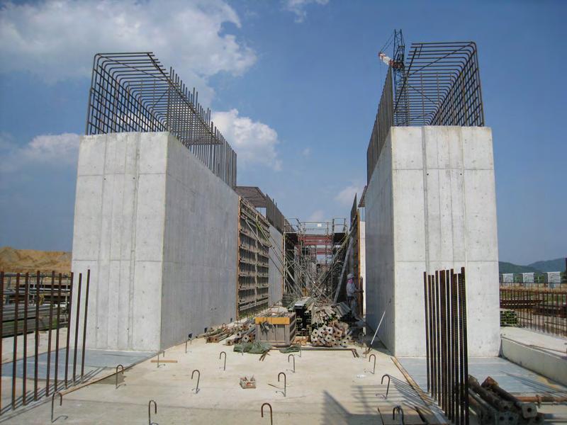

6 T. June GeV XFEL Construction 2008 May


7 8 GeV XFEL Construction T. SCSS & XFEL/SPring September Undulator Hall 400 m accelerator Accelerator tunnel Assembly Hall


8 Tunnel Construction 2008 September T. SCSS & XFEL/SPring Undulator Hall 400 m accelerator Steel Mesh & Level Guide Rail Beam Dump
 Higher electron density at the undulator. 2) C-band accelerator High gradient (Ea ~ 35 MV/m) Compact accelerator.")
9 Concept of XFEL/SPring-8 Thermionic Electron Gun 8 GeV C-band accelerator In-Vacuum Undulators X-ray Laser Electron Beam SASE-FEL Beam Dump 1) Electron gun Low emittance (εn ~ 0.7π mm*mrad) Higher electron density at the undulator. 2) C-band accelerator High gradient (Ea ~ 35 MV/m) Compact accelerator. 3) In-vacuum undulator Short period (λu ~ 18 mm) Shorter wavelength with lower electron energy.
 Acceleration Ea = 35 MV/m V/V ~ 0.01%rms φ ~ 0.5 deg.")
10 500 kev 1 A x 1 ns 8 GeV XFEL Machine Layout 30 MeV 100 A 400 MeV 1 ka Bunch compression Injector S-band C-band (42 off-crest) V/V ~ 0.01%rms φ ~ 0.2 deg.rms 1.4 GeV 3 ka C-band (crest) Acceleration Ea = 35 MV/m V/V ~ 0.01%rms φ ~ 0.5 deg.rms 8 GeV 3 ka Undulators X-ray Laser λmin < 0.1 nm
11
12 T. June 2008 Expected Performance of XFEL/SPring-8 Wavelength Peak Power X-ray Pulse Length X-ray Pulse Energy Photon Flux Peak Brightness Pulse Repetition Bunch per Pulse e Beam Multi-bunch Option < 0.1 nm ~ 20 GW ~ 20 fs 0.4 mj 2 x p/pulse 1 x p/mm 2 /mrad 2 /0.1% BW 10 ~ 60 pps 1 ~ 50 (4.2 nsec spacing) 8 GeV x 0.3 nc 0.8 πmm.mrad, 3 ka 50 x 60 = 3000 pps Expected X-ray pulse of 0.1 nm (SIMPLEX simulation)
13 Gun 238 MHz 476 MHz RF Acceleration System in 8 GeV SPring-8 XFEL Injector L-band s1 S-band 50 MeV 450 MeV s4 T.Shintake 2007 March c C-band Sector-1 BC-0 BC-2 BC-1 c GeV c GeV c2-1 C-band Sector-2 c GeV C-band Sector-3 c3-1 c3-16 C-band Klystron 64 Acc. Str GeV c4-1 C-band Sector-4 c GeV To Undulator


14 C-band RF system

15 400 m Long C-band Main Accelerator


16 T. June 2008 C-band Accelerator for Multi-bunch Option 13,000 cells are under mass production. T. Shintake, Choke Mode Cavity, Jpn. J. Appl. Phys. Vol. 31 pp. L1567-L1570, November 1992 Higher Order Mode Damping for Multi-bunch operation. Maximum 50 bunches x 1 nc, at 4.2 nsec spacing Sadao Miura, MITSUBISHI Heavy Ind, April 2008

17 128 tubes of the C-band Accelerating Structure are in mass-production for 8 GeV linac. T. Shintake@ June 2008

18 C-band accelerator at the prototype accelerator Waveguide from rf pulse compressor Undulators After accelerating structure 120 MeV 250 MeV After rf pulse compressor Peak 200 MW Unit#1 Unit#2 Accelerating structure 1.8 m x 4 colums Klystron output 50 MW Klystron voltage -330 kv Since May 2008 run period, Accelerating gradient = 36.6 MV/m (@unit#2) So far, no trouble, very rare trip rate (rf discharge)


19 RF trip rate in 37 MV/m operation User run (May 2008 ~ July 2008) Total: 299 hours, 10 pps Fault: 26 times Safety interlock 4 Control 2 C-band #2 4 Reason GUN 11 RF trip 2 High voltage 1 Fake interlocked 1 C-band #1 0 S-band 2 Buncher 3 This is acceptable rate for XFEL C-band is stably operated.

20 Klystron Modulator for C-band, S-band 50 MW Klystrons Modulator Mass Production


21 Modulator Mass Production Ship Engine maker KOTOBUKI at AIOI city makes modulator tank. Circuit blocks will be mounted On base plate, which is precisely machined, suitable for mass-production.


22 T. June MW Klystron and Modulator for XFEL Max RF power : 50 and S-band Max Pulse Power: 110 MW Max Rep Rate : 60 pps Size : 1m x 1m x 1.7 m Total Weight : 4.5 ton Insulation oil filled. Water cooled. Perfect EM noise shield. Ready for mass production of 70 units. Pulse Voltage Stability 10 ppm. rms


23 High power test stand PFN HV charger - 50 ppm (p-p) repeatability at PFN voltage Accelerating structure RF pulse compressor Modulator - PFN, thyratron and pulse transformer in one oil tank High power test of rf components - Sample check before installation to XFEL

 which are used at 8")
24 High power test stand for XFEL RF pulse compressor Klystron Accelerating structure Modulator -PFN, thyratron and pulse transformer in one oil tank - good stability for XFEL 50 ppm (p-p) at PFN voltage Combined test of the C-band unit (rf components, klystrons, power supplies, ) which are used at 8 GeV machine.
25 Q-D-V44 Q-D-V44 Electron Beam SP-8 XFEL Undulator Line Undulator Lines Elxperimental Stations Bending Magnet 1.2 m FEL light 5 m ST -D-V44 ST -D-V44 ST -D-V44 ST -D-V44 UND-ID-1 ~110 m 18 Undulator Segments Drift Section GV,PM,CT,BPM Focusing Q Phase Shifter Steering Coils


26 Undulator for XFEL/SPring-8 Takashi Tanaka Magnetic Circuit Hybrid Length Period 5 m 18mm NeFeB Hybrid Number of Periods 276 Gap Minimum 2mm At 1 ope 4mm K-value Max Max At 1 ope 40mm


27 Undulator for 8GeV X-ray FEL SPring-8 Outlook of 5 m long in-vacuum undulator for X-ray FEL. 18mm NeFeB magnet array, undulator period is 18 mm.
28 SAFALI Field Measurement System SAFALI: Self-Aligned Field Analyzer with Laser Instrumentation Simple mover of hole probe. fit within vacuum chamber. Laser beam guide for xy-displacement, and position feedback on guide rail. Laser distance meter for z-location. Takashi Tanaka laser scale corner cube laser diode 2-axis stage rail carriage stepper motor

29
30 Field Tuning by SAFALI At unit-1, tuning taper by 2 μm At unit-3, tuning offset by -2 μm Field reproduced the field before installing magnet inside the vacuum chamber Phase Error (degree) (a) σ φ =7.2 o Before Tuning Gap Fine Tuning (b) σ φ =3.3 o After Tuning Pole Number Pole Number

31 SCSS Test Accelerator Performance T. June 2008

32 50~60 nm, 30 μj/pulse Multi-photon absorption. Wavefront distortion measurement. etc. T. June 2008 SCSS Test Accelerator User Run Has been Started in 2008
33 T. June 2008 CeB6 Crystal Cathode has reached its lifetime after 20,000 hour operation. January 2008, right after the new year holiday, the emission current decreased quickly by 50%. It has been nicely running for user experiment till end of December 2007, (60 nm full saturation) This crystal was installed in October Lifetime is 20,000 hours, which is shorter than we expected. But, it is fairly long enough, we decided to regularly change the crystal every year at summer shutdown. It took two weeks to replace cathode and tuning beam to recover full saturated lasing.


34 Single-crystal CeB 6 Cathode for the SCSS Low-emittance Injector 500 kv Electron Gun Heating Cathode Diameter : φ3 mm Temperature : ~1500 deg.c Beam Voltage : 500 kv Peak Current : 1 A Pulse Width : ~2 μs


35 2008/01/28 First experience, but team did nice work. T. June 2008 We replaced CeB6 crystal in SCSS accelerator, after 20,000 hour operation. Anode flange had color change.
 Concave geometry")
 Surface is fairly smooth, (2) covered by carbon contamination (lowered")
36 It was found the cathode surface became concave of 0.2 mm deep from the initial flat surface. It corresponds to evaporation speed of 10 nm/hour ( 10 nm/h x 20,000 h = 200 micron-meter) Concave geometry made beam slightly focusing, but did not break emittance. Electron microscope study showed (1) Surface is fairly smooth, (2) covered by carbon contamination (lowered electron emission). CeB6 cathode after 20,000 hour use. T. Shintake@ June 2008


37 T. June 2008 Cathode Surface EM Image There is no evidence was found by SEM imaging, no carbon contamination. Graphite holder CeB6 After 20,000h operation CeB6 New, before usage CeB6 Material Evaporated, 200 um. Carbon sintered with boron from CeB6
38 T. June 2008 SCSS Test Accelerator Performance Running Always in Saturation Mode 50~60 nm (wavelength is limited by accelerator energy) 30 uj/pulse energy 200 fs pulse length E-beam 250 MeV, 0.4 nc, < 1 psec, 10 pps E-beam Emittance in the undulator is 0.7 π.mm.mrad Determined from FEL gain measurement.
39 SASE Performance at Saturation Item Achieved Performance Wavelength Repetition Rate Pulse Energy Pulse Energy Fluctuation(STD) Laser Size (FWHM)# Pointing Stability# 50~60 nm < 20 Hz ~10% ~3mm ~5% to the beam size 0.6% Averaged Spectrum Width (FWHM) # 10m downstream location of the source point 4
40 FEL test accelerator (2005~ ) To confirm feasibility of 1. Bunch compression for SASE lasing 2. Accelerator components 3. Experiment with FEL light. Total length : 60 m (1/10 of 8 GeV machine) E: 0.5 MeV E: 40 MeV E: 250 MeV 238 MHz PRE-BUNCHER 500 kv PULSED GUN S-BAND LINAC 1 m 2 m C-BAND LINAC UNDULATOR L: 9 m (4.5 x 2) USER AREA BEAM DEFLECTOR 476 MHz BOOSTER Acc: 1.8 m x 4 Kly: 50 MW x 2 λu: 15 mm Kmax: 1.3 Gap: 3.7 mm
41 Saturation of SASE Amplification The normalized emittance is estimated to be 0.7πmm.mrad! Exponential Growth Saturation 5
 50")
42 Stability of SASE Intensity Intensity variation = 11%(1σ) 50 nm 6

43 T. June 2008

44 HHG Seeding Experiment At SCSS Test Accelerator G. Lambert, LOA ENSTA Palaiseau, France
45 T. June 2008 Summary SCSS Test Accelerator is running fully saturated condition. E-beam Emittance in undulator is around 0.7 π.mm.mrad. This is enough for X-ray FEL at 0.1 nm range. Construction of 8 GeV XFEL/SPring-8 is going well. First X-ray beam : End of FY 2010
46
H. Maesaka*, K. Togawa, T. Inagaki, K. Onoe, T. Tanaka, A. Higashiya, H. Baba, H. Matsumoto, H. Tanaka, Y. Otake and T. Shintake FLS 2010, SLAC
 H. Maesaka*, K. Togawa, T. Inagaki, K. Onoe, T. Tanaka, A. Higashiya, H. Baba, H. Matsumoto, H. Tanaka, Y. Otake and T. Shintake FLS 2010, SLAC 1 Introduction Outline X-ray FEL Project at SPring-8 SCSS
The CeB6 Electron Gun for the Soft-X-ray FEL Project at SPring-8
 May 25, 2004 DESY, Hamburg, Germany The CeB6 Electron Gun for the Soft-X-ray FEL Project at SPring-8 K. Togawa SPring-8 / RIKEN Harima Institute T. Shintake, H. Baba, T. Inagaki, T. Tanaka SPring-8 / RIKEN
SCSS Prototype Accelerator -- Its outline and achieved beam performance --
 SCSS Prototype Accelerator -- Its outline and achieved beam performance -- Hitoshi TANAKA RIKEN, XFEL Project Office 1 Content 1. Light Quality; SPring-8 v.s. XFEL 2. What are the critical issues? 3. Mission
Free-electron laser SACLA and its basic. Yuji Otake, on behalf of the members of XFEL R&D division RIKEN SPring-8 Center
 Free-electron laser SACLA and its basic Yuji Otake, on behalf of the members of XFEL R&D division RIKEN SPring-8 Center Light and Its Wavelength, Sizes of Material Virus Mosquito Protein Bacteria Atom
PAL LINAC UPGRADE FOR A 1-3 Å XFEL
 PAL LINAC UPGRADE FOR A 1-3 Å XFEL J. S. Oh, W. Namkung, Pohang Accelerator Laboratory, POSTECH, Pohang 790-784, Korea Y. Kim, Deutsches Elektronen-Synchrotron DESY, D-603 Hamburg, Germany Abstract With
X-ray Free-electron Lasers
 X-ray Free-electron Lasers Ultra-fast Dynamic Imaging of Matter II Ischia, Italy, 4/30-5/3/ 2009 Claudio Pellegrini UCLA Department of Physics and Astronomy Outline 1. Present status of X-ray free-electron
Short Pulse, Low charge Operation of the LCLS. Josef Frisch for the LCLS Commissioning Team
 Short Pulse, Low charge Operation of the LCLS Josef Frisch for the LCLS Commissioning Team 1 Normal LCLS Parameters First Lasing in April 10, 2009 Beam to AMO experiment August 18 2009. Expect first user
Towards a Low Emittance X-ray FEL at PSI
 Towards a Low Emittance X-ray FEL at PSI A. Adelmann, A. Anghel, R.J. Bakker, M. Dehler, R. Ganter, C. Gough, S. Ivkovic, F. Jenni, C. Kraus, S.C. Leemann, A. Oppelt, F. Le Pimpec, K. Li, P. Ming, B. Oswald,
S2E (Start-to-End) Simulations for PAL-FEL. Eun-San Kim
 Simulations for PAL-FEL. Eun-San Kim") S2E (Start-to-End) Simulations for PAL-FEL Aug. 25 2008 Kyungpook Nat l Univ. Eun-San Kim 1 Contents I Lattice and layout for a 10 GeV linac II Beam parameters and distributions III Pulse-to-pulse stability
S2E (Start-to-End) Simulations for PAL-FEL Aug. 25 2008 Kyungpook Nat l Univ. Eun-San Kim 1 Contents I Lattice and layout for a 10 GeV linac II Beam parameters and distributions III Pulse-to-pulse stability
X-band Experience at FEL
 X-band Experience at FERMI@Elettra FEL Gerardo D Auria Elettra - Sincrotrone Trieste GdA_TIARA Workshop, Ångström Laboratory, June 17-19, 2013 1 Outline The FERMI@Elettra FEL project Machine layout and
X-band RF driven hard X-ray FELs. Yipeng Sun ICFA Workshop on Future Light Sources March 5-9, 2012
 X-band RF driven hard X-ray FELs Yipeng Sun ICFA Workshop on Future Light Sources March 5-9, 2012 Motivations & Contents Motivations Develop more compact (hopefully cheaper) FEL drivers, L S C X-band (successful
FLASH/DESY, Hamburg. Jörg Rossbach University of Hamburg & DESY, Germany - For the FLASH Team -
 First Lasing below 7nm Wavelength at FLASH/DESY, Hamburg Jörg Rossbach University of Hamburg & DESY, Germany - For the FLASH Team - email: joerg.rossbach@desy.de FLASH: The first FEL user facility for
Simulations of the IR/THz source at PITZ (SASE FEL and CTR)
") Simulations of the IR/THz source at PITZ (SASE FEL and CTR) Introduction Outline Simulations of SASE FEL Simulations of CTR Summary Issues for Discussion Mini-Workshop on THz Option at PITZ DESY, Zeuthen
Simulations of the IR/THz source at PITZ (SASE FEL and CTR) Introduction Outline Simulations of SASE FEL Simulations of CTR Summary Issues for Discussion Mini-Workshop on THz Option at PITZ DESY, Zeuthen
SLS at the Paul Scherrer Institute (PSI), Villigen, Switzerland
, Villigen, Switzerland") SLS at the Paul Scherrer Institute (PSI), Villigen, Switzerland Michael Böge 1 SLS Team at PSI Michael Böge 2 Layout of the SLS Linac, Transferlines Booster Storage Ring (SR) Beamlines and Insertion Devices
SLS at the Paul Scherrer Institute (PSI), Villigen, Switzerland Michael Böge 1 SLS Team at PSI Michael Böge 2 Layout of the SLS Linac, Transferlines Booster Storage Ring (SR) Beamlines and Insertion Devices
Simulations of the IR/THz Options at PITZ (High-gain FEL and CTR)
") Case Study of IR/THz source for Pump-Probe Experiment at the European XFEL Simulations of the IR/THz Options at PITZ (High-gain FEL and CTR) Introduction Outline Simulations of High-gain FEL (SASE) Simulation
Case Study of IR/THz source for Pump-Probe Experiment at the European XFEL Simulations of the IR/THz Options at PITZ (High-gain FEL and CTR) Introduction Outline Simulations of High-gain FEL (SASE) Simulation
Vertical Polarization Option for LCLS-II. Abstract
 SLAC National Accelerator Lab LCLS-II TN-5-8 March 5 Vertical Polarization Option for LCLS-II G. Marcus, T. Raubenheimer SLAC, Menlo Park, CA 95 G. Penn LBNL, Berkeley, CA 97 Abstract Vertically polarized
Low slice emittance preservation during bunch compression
 Low slice emittance preservation during bunch compression S. Bettoni M. Aiba, B. Beutner, M. Pedrozzi, E. Prat, S. Reiche, T. Schietinger Outline. Introduction. Experimental studies a. Measurement procedure
Short Introduction to CLIC and CTF3, Technologies for Future Linear Colliders
 Short Introduction to CLIC and CTF3, Technologies for Future Linear Colliders Explanation of the Basic Principles and Goals Visit to the CTF3 Installation Roger Ruber Collider History p p hadron collider
H. Maesaka*, H. Ego, T. Hara, A. Higashiya, S. Inoue, S. Matsubara, T. Ohshima, K. Tamasaku, H. Tanaka, T. Tanikawa, T. Togashi, K. Togawa, H.
 H. Maesaka*, H. Ego, T. Hara, A. Higashiya, S. Inoue, S. Matsubara, T. Ohshima, K. Tamasaku, H. Tanaka, T. Tanikawa, T. Togashi, K. Togawa, H. Tomizawa, M. Yabashi, K. Yanagida, T. Shintake and Y. Otake
Diagnostic Systems for Characterizing Electron Sources at the Photo Injector Test Facility at DESY, Zeuthen site
 1 Diagnostic Systems for Characterizing Electron Sources at the Photo Injector Test Facility at DESY, Zeuthen site Sakhorn Rimjaem (on behalf of the PITZ team) Motivation Photo Injector Test Facility at
LCLS Commissioning Status
 LCLS Commissioning Status Paul Emma (for the LCLS Commissioning Team) June 20, 2008 LCLS ANL LLNL UCLA FEL Principles Electrons slip behind EM wave by λ 1 per undulator period ( (λ u ) x K/γ e λ u v x
ACCELERATOR LAYOUT AND PHYSICS OF X-RAY FREE-ELECTRON LASERS
 ACCELERATOR LAYOUT AND PHYSICS OF X-RAY FREE-ELECTRON LASERS W. Decking, DESY, Notkestraße 85, 22603 Hamburg, Germany Abstract X-ray Free-Electron Lasers facilities are planned or are already under construction
LCLS Undulators Present Status and Future Upgrades
 LCLS Undulators Present Status and Future Upgrades Heinz-Dieter Nuhn LCLS Undulator Group Leader 1 1 Heinz-Dieter Nuhn Linac Coherent Light Source INJECTOR LINAC BEAM TRANSPORT UNDULATOR HALL 2 2 Heinz-Dieter
Generation and characterization of ultra-short electron and x-ray x pulses
 Generation and characterization of ultra-short electron and x-ray x pulses Zhirong Huang (SLAC) Compact XFEL workshop July 19-20, 2010, Shanghai, China Ultra-bright Promise of XFELs Ultra-fast LCLS Methods
Length of beam system = 910m. S. Reiche X var = ~50m ~ 650m / Y. Kim FEL-KY ~150m. ~60m. LaserHutch2 (access during operation)
") Laser Laser HHG Diagnostic ATHOS PORTHOS ARAMIS THz-Pump P A U L S C H E R R E R I N S T I T U T Length of beam system = 910m &'!( Test & Commissioning steps (A,B,C) A11 Conv. Gun & Injector A12 LINAC
Laser Laser HHG Diagnostic ATHOS PORTHOS ARAMIS THz-Pump P A U L S C H E R R E R I N S T I T U T Length of beam system = 910m &'!( Test & Commissioning steps (A,B,C) A11 Conv. Gun & Injector A12 LINAC
OVERVIEW OF FELS UNDER CONSTRUCTION INCLUDING FELs AT FERMI ELETTRA, SPRING-8 AND FRASCATI SPARC
 OVERVIEW OF FELS UNDER CONSTRUCTION INCLUDING FELs AT FERMI ELETTRA, SPRING-8 AND FRASCATI SPARC Giuseppe Penco, ELETTRA, Basovizza, Italy Abstract This talk will report the present status of the worlwide
Linac Based Photon Sources: XFELS. Coherence Properties. J. B. Hastings. Stanford Linear Accelerator Center
 Linac Based Photon Sources: XFELS Coherence Properties J. B. Hastings Stanford Linear Accelerator Center Coherent Synchrotron Radiation Coherent Synchrotron Radiation coherent power N 6 10 9 incoherent
Linac optimisation for the New Light Source
 Linac optimisation for the New Light Source NLS source requirements Electron beam requirements for seeded cascade harmonic generation LINAC optimisation (2BC vs 3 BC) CSR issues energy chirp issues jitter
FACET-II Design Update
 FACET-II Design Update October 17-19, 2016, SLAC National Accelerator Laboratory Glen White FACET-II CD-2/3A Director s Review, August 9, 2016 Planning for FACET-II as a Community Resource FACET-II Photo
SPPS: The SLAC Linac Bunch Compressor and Its Relevance to LCLS
 LCLS Technical Advisory Committee December 10-11, 2001. SPPS: The SLAC Linac Bunch Compressor and Its Relevance to LCLS Patrick Krejcik LCLS Technical Advisory Committee Report 1: July 14-15, 1999 The
A 6 GeV Compact X-ray FEL (CXFEL) Driven by an X-Band Linac
 Driven by an X-Band Linac") A 6 GeV Compact X-ray FEL (CXFEL) Driven by an X-Band Linac Zhirong Huang, Faya Wang, Karl Bane and Chris Adolphsen SLAC Compact X-Ray (1.5 Å) FEL Parameter symbol LCLS CXFEL unit Bunch Charge Q 250 250
A 6 GeV Compact X-ray FEL (CXFEL) Driven by an X-Band Linac Zhirong Huang, Faya Wang, Karl Bane and Chris Adolphsen SLAC Compact X-Ray (1.5 Å) FEL Parameter symbol LCLS CXFEL unit Bunch Charge Q 250 250
Experimental Optimization of Electron Beams for Generating THz CTR and CDR with PITZ
 Experimental Optimization of Electron Beams for Generating THz CTR and CDR with PITZ Introduction Outline Optimization of Electron Beams Calculations of CTR/CDR Pulse Energy Summary & Outlook Prach Boonpornprasert
Experimental Measurements of the ORION Photoinjector Drive Laser Oscillator Subsystem
 Experimental Measurements of the ORION Photoinjector Drive Laser Oscillator Subsystem D.T Palmer and R. Akre Laser Issues for Electron RF Photoinjectors October 23-25, 2002 Stanford Linear Accelerator
LOLA: Past, present and future operation
 LOLA: Past, present and future operation FLASH Seminar 1/2/29 Christopher Gerth, DESY 8/5/29 FLASH Seminar Christopher Gerth 1 Outline Past Present Future 8/5/29 FLASH Seminar Christopher Gerth 2 Past
Expected properties of the radiation from VUV-FEL / femtosecond mode of operation / E.L. Saldin, E.A. Schneidmiller, M.V. Yurkov
 Expected properties of the radiation from VUV-FEL / femtosecond mode of operation / E.L. Saldin, E.A. Schneidmiller, M.V. Yurkov TESLA Collaboration Meeting, September 6-8, 2004 Experience from TTF FEL,
Hiromitsu TOMIZAWA XFEL Division /SPring-8
 TUPLB10 (Poster: TUPB080) Non-destructive Real-time Monitor to measure 3D- Bunch Charge Distribution with Arrival Timing to maximize 3D-overlapping for HHG-seeded EUV-FEL Hiromitsu TOMIZAWA XFEL Division
Diagnostics at the MAX IV 3 GeV storage ring during commissioning. PPT-mall 2. Åke Andersson On behalf of the MAX IV team
 Diagnostics at the MAX IV 3 GeV storage ring during commissioning PPT-mall 2 Åke Andersson On behalf of the MAX IV team IBIC Med 2016, linje Barcelona Outline MAX IV facility overview Linac injector mode
Undulator radiation from electrons randomly distributed in a bunch
 Undulator radiation from electrons randomly distributed in a bunch Normally z el >> N u 1 Chaotic light Spectral property is the same as that of a single electron /=1/N u Temporal phase space area z ~(/
Layout of the HHG seeding experiment at FLASH
 Layout of the HHG seeding experiment at FLASH V. Miltchev on behalf of the sflash team: A. Azima, J. Bödewadt, H. Delsim-Hashemi, M. Drescher, S. Düsterer, J. Feldhaus, R. Ischebeck, S. Khan, T. Laarmann
Microbunching Workshop 2010 March 24, 2010, Frascati, Italy. Zhirong Huang
 Measurements of the LCLS Laser Heater and its impact on the LCLS FEL Performance Z. Huang for the LCLS commissioning team LCLS 1 1 Outline Introduction LCLS setup and measurements Effects on FEL performance
ICFA ERL Workshop Jefferson Laboratory March 19-23, 2005 Working Group 1 summary Ilan Ben-Zvi & Ivan Bazarov
 ICFA ERL Workshop Jefferson Laboratory March 19-23, 2005 Working Group 1 summary Ilan Ben-Zvi & Ivan Bazarov Sincere thanks to all WG1 participants: Largest group, very active participation. This summary
STATUS REPORT ON STORAGE RING REALIGNMENT AT SLRI
 STATUS REPORT ON STORAGE RING REALIGNMENT AT SLRI S. Srichan #, A. Kwankasem, S. Boonsuya, B. Boonwanna, V. Sooksrimuang, P. Klysubun Synchrotron Light Research Institute, 111 University Ave, Muang District,
Electron Linear Accelerators & Free-Electron Lasers
 Electron Linear Accelerators & Free-Electron Lasers Bryant Garcia Wednesday, July 13 2016. SASS Summer Seminar Bryant Garcia Linacs & FELs 1 of 24 Light Sources Why? Synchrotron Radiation discovered in
Dark Current at Injector. Jang-Hui Han 27 November 2006 XFEL Beam Dynamics Meeting
 Dark Current at Injector Jang-Hui Han 27 November 2006 XFEL Beam Dynamics Meeting Considerations for the guns Ultra-low slice emittance of electron beams higher gradient at the gun cavity solenoid field
4GLS Status. Susan L Smith ASTeC Daresbury Laboratory
 4GLS Status Susan L Smith ASTeC Daresbury Laboratory Contents ERLP Introduction Status (Kit on site ) Plan 4GLS (Conceptual Design) Concept Beam transport Injectors SC RF FELs Combining Sources May 2006
LCLS-II SCRF start-to-end simulations and global optimization as of September Abstract
 SLAC National Accelerator Lab LCLS-II TN-17-4 February 217 LCLS-II SCRF start-to-end simulations and global optimization as of September 216 G. Marcus SLAC, Menlo Park, CA 9425 J. Qiang LBNL, Berkeley,
Development of Cs 2 Te photocathode RF gun system for compact THz SASE-FEL
 Development of Cs 2 Te photocathode RF gun system for compact THz SASE-FEL R. Kuroda, H. Ogawa, N. Sei, H. Toyokawa, K. Yagi-Watanabe, M. Yasumoto, M. Koike, K. Yamada, T. Yanagida*, T. Nakajyo*, F. Sakai*
VELA/CLARA as Advanced Accelerator Studies Test-bed at Daresbury Lab.
 VELA/CLARA as Advanced Accelerator Studies Test-bed at Daresbury Lab. Yuri Saveliev on behalf of VELA and CLARA teams STFC, ASTeC, Cockcroft Institute Daresbury Lab., UK Outline VELA (Versatile Electron
The VELA and CLARA Test Facilities at Daresbury Laboratory Peter McIntosh, STFC on behalf of the VELA and CLARA Development Teams
 The VELA and CLARA Test Facilities at Daresbury Laboratory Peter McIntosh, STFC on behalf of the VELA and CLARA Development Teams Outline VELA & CLARA Accelerators VELA Commissioning VELA Exploitation
Status of linear collider designs:
 Status of linear collider designs: Electron and positron sources Design overview, principal open issues G. Dugan March 11, 2002 Electron sourcesfor 500 GeV CM machines Parameter TESLA NLC CLIC Cycle rate
REVIEW OF THE WORLDWIDE SASE FEL DEVELOPMENT
 REVIEW OF THE WORLDWIDE SASE FEL DEVELOPMENT Tsumoru Shintake # RIKEN/SPring-8, Hyogo 679-5148 Japan. Abstract Three major X-ray FELs are now under construction: LCLS[1] at SLAC Stanford, XFEL/SPring-8[2]
4 FEL Physics. Technical Synopsis
 4 FEL Physics Technical Synopsis This chapter presents an introduction to the Free Electron Laser (FEL) physics and the general requirements on the electron beam parameters in order to support FEL lasing
FLASH overview. Nikola Stojanovic. PIDID collaboration meeting, Hamburg,
 FLASH overview Nikola Stojanovic PIDID collaboration meeting, Hamburg, 16.12.2011 Outline Overview of the FLASH facility Examples of research at FLASH Nikola Stojanovic PIDID: FLASH overview Hamburg, December
Demonstration of Energy-Chirp Control in Relativistic Electron Bunches at LCLS Using a Corrugated Structure. Karl Bane, 7 April 2017,, KEK
 Demonstration of Energy-Chirp Control in Relativistic Electron Bunches at LCLS Using a Corrugated Structure Karl Bane, 7 April 2017,, KEK Introduction At the end of acceleration in an X-ray FEL, the beam
FACET-II Design, Parameters and Capabilities
 FACET-II Design, Parameters and Capabilities 217 FACET-II Science Workshop, October 17-2, 217 Glen White Overview Machine design overview Electron systems Injector, Linac & Bunch compressors, Sector 2
Status of Proof-of-Principle Experiment of Coherent Electron Cooling at BNL
 Status of Proof-of-Principle Experiment of Coherent Electron Cooling at BNL Outline 2 Why we doing it? What is Coherent electron Cooling System description Subsystem performance Plan for Run 18 e-n Luminosity
Waseda University. Design of High Brightness Laser-Compton Light Source for EUV Lithography Research in Shorter Wavelength Region
 Waseda University Research Institute for Science and Engineering Design of High Brightness Laser-Compton Light Source for EUV Lithography Research in Shorter Wavelength Region Research Institute for Science
Potential use of erhic s ERL for FELs and light sources ERL: Main-stream GeV e - Up-gradable to 20 + GeV e -
 Potential use of erhic s ERL for FELs and light sources Place for doubling energy linac ERL: Main-stream - 5-10 GeV e - Up-gradable to 20 + GeV e - RHIC Electron cooling Vladimir N. Litvinenko and Ilan
Undulator Commissioning Spectrometer for the European XFEL
 Undulator Commissioning Spectrometer for the European XFEL FEL Beam Dynamics Group meeting DESY, Hamburg, Nov. 9 th 010 Wolfgang Freund, WP74 European XFEL wolfgang.freund@xfel.eu Contents Undulator commissioning
High average current photo injector (PHIN) for the CLIC Test Facility at CERN
 for the CLIC Test Facility at CERN") High average current photo injector (PHIN) for the CLIC Test Facility at CERN CLIC and CTF3 motivation Photo injectors, PHIN Emittance measurements Long pulse operation, time resolved measurements Cathode
High average current photo injector (PHIN) for the CLIC Test Facility at CERN CLIC and CTF3 motivation Photo injectors, PHIN Emittance measurements Long pulse operation, time resolved measurements Cathode
The European XFEL in Hamburg: Status and beamlines design
 UVX 2010 (2011) 63 67 DOI: 10.1051/uvx/2011009 C Owned by the authors, published by EDP Sciences, 2011 The European XFEL in Hamburg: Status and beamlines design J. Gaudin, H. Sinn and Th. Tschentscher
FEL R&D Activities at SINAP. Zhentang Zhao for the Project Team Shanghai Institute of Applied Physics, CAS SHanghai, Dec.
 FEL R&D Activities at SINAP Zhentang Zhao for the Project Team Shanghai Institute of Applied Physics, CAS SHanghai, Dec.11-12, 2008 Outline Introduction to the SXFEL Project; The SXFEL construction plan;
R&D experiments at BNL to address the associated issues in the Cascading HGHG scheme
 R&D experiments at BNL to address the associated issues in the Cascading HGHG scheme Li Hua Yu for DUV-FEL Team National Synchrotron Light Source Brookhaven National Laboratory FEL2004 Outline The DUVFEL
Femto-second FEL Generation with Very Low Charge at LCLS
 Femto-second FEL Generation with Very Low Charge at LCLS Yuantao Ding, For the LCLS commissioning team X-ray Science at the Femtosecond to Attosecond Frontier workshop May 18-20, 2009, UCLA SLAC-PUB-13525;
LCLS Injector Prototyping at the GTF
 LCLS Injector Prototyping at at the GTF John John Schmerge, SLAC SLAC November 3, 3, 23 23 GTF GTF Description Summary of of Previous Measurements Longitudinal Emittance Transverse Emittance Active LCLS
New Electron Source for Energy Recovery Linacs
 New Electron Source for Energy Recovery Linacs Ivan Bazarov 20m Cornell s photoinjector: world s brightest electron source 1 Outline Uses of high brightness electron beams Physics of brightness High brightness
Dark current at the Euro-XFEL
 Dark current at the Euro-XFEL Jang-Hui Han DESY, MPY Observations at PITZ and FLASH Estimation for the European XFEL Ideas to reduce dark current at the gun DC at FLASH RF gun M1 M2 M3 M4 M5 M6 M7 6 undulator
The SCSS test accelerator Free-Electron Laser seeded by harmonics produced in gas
 UVX 2008 (2009) 85 91 C EDP Sciences, 2009 DOI: 10.1051/uvx/2009014 The SCSS test accelerator Free-Electron Laser seeded by harmonics produced in gas G. Lambert 1,T.Hara 2, T. Tanikawa 3, D. Garzella 4,
Research Laboratory for Quantum Beam Science
 L band Linac 60 Co γ ray irradiation facility Research Laboratory for Quantum Beam Science http://www.sanken.osaka u.ac.jp/labs/rl/ S band Laser Photocathode RF Linac ISIR, Osaka University 150 MeV S band
SPARCLAB. Source For Plasma Accelerators and Radiation Compton. On behalf of SPARCLAB collaboration
 SPARCLAB Source For Plasma Accelerators and Radiation Compton with Laser And Beam On behalf of SPARCLAB collaboration EMITTANCE X X X X X X X X 2 BRIGHTNESS (electrons) B n 2I nx ny A m 2 rad 2 The current
MaRIE. MaRIE X-Ray Free-Electron Laser Pre-Conceptual Design
 Operated by Los Alamos National Security, LLC, for the U.S. Department of Energy MaRIE (Matter-Radiation Interactions in Extremes) MaRIE X-Ray Free-Electron Laser Pre-Conceptual Design B. Carlsten, C.
Introduction. Thermoionic gun vs RF photo gun Magnetic compression vs Velocity bunching. Probe beam design options
 Introduction Following the 19/05/04 meeting at CERN about the "CTF3 accelerated programme", a possible french contribution has been envisaged to the 200 MeV Probe Beam Linac Two machine options were suggested,
Photo Injector Test facility at DESY, Zeuthen site
 Photo Injector Test facility at DESY, Zeuthen site PITZ EXPERIENCE ON THE EXPERIMENTAL OPTIMIZATION OF THE RF PHOTO INJECTOR FOR THE EUROPEAN XFEL Mikhail Krasilnikov (DESY) for the PITZ Team FEL 2013
ILC Particle Sources -Electron and PositronMasao KURIKI (Hiroshima University)
") ILC Particle Sources -Electron and PositronMasao KURIKI (Hiroshima University) Introduction Electron Polarization is important for ILC. NEA GaAs is practically the only solution. Positron polarization
ILC Particle Sources -Electron and PositronMasao KURIKI (Hiroshima University) Introduction Electron Polarization is important for ILC. NEA GaAs is practically the only solution. Positron polarization
The New Superconducting RF Photoinjector a High-Average Current & High-Brightness Gun
 The New Superconducting RF Photoinjector a High-Average Current & High-Brightness Gun Jochen Teichert for the BESSY-DESY-FZD-MBI collaboration and the ELBE crew High-Power Workshop, UCLA, Los Angeles 14
CEPC Linac Injector. HEP Jan, Cai Meng, Guoxi Pei, Jingru Zhang, Xiaoping Li, Dou Wang, Shilun Pei, Jie Gao, Yunlong Chi
 HKUST Jockey Club Institute for Advanced Study CEPC Linac Injector HEP218 22 Jan, 218 Cai Meng, Guoxi Pei, Jingru Zhang, Xiaoping Li, Dou Wang, Shilun Pei, Jie Gao, Yunlong Chi Institute of High Energy
DESIGN AND CONSTRUCTION OF LOW ENERGY ELECTRON ACCELERATORS AT SINP MSU
 DESIGN AND CONSTRUCTION OF LOW ENERGY ELECTRON ACCELERATORS AT SINP MSU V. Shvedunov Skobeltsyn Institute of Nuclear Physics Lomonosov Moscow State University 26 November 2013 Betatron 1959-1985 Low intensity
Transverse Beam Optics of the FLASH Facility
 Transverse Beam Optics of the FLASH Facility ( current status and possible updates ) Nina Golubeva and Vladimir Balandin XFEL Beam Dynamics Group Meeting, 18 June 2007 Outline Different optics solutions
Fine Alignment of the ATF Damping Ring
 Fine Alignment of the ATF Damping Ring M. Takano, S. Araki (a), Y. Funahashi (a), H. Hayano (a), T. Matsui (b), J. Urakawa (a) Toho University 2 2 1 Miyama, Funabashi, Chiba 275, Japan (a) KEK, High Energy
The Booster has three magnet systems for extraction: Kicker Ke, comprising two identical magnets and power supplies Septum Se
 3.2.7 Booster Injection and Extraction 3.2.7.1 Overview The Booster has two magnet systems for injection: Septum Si Kicker Ki The Booster has three magnet systems for extraction: Kicker Ke, comprising
Greenfield FELs. John Galayda, SLAC Kwang-Je Kim, ANL (Presenter) James Murphy, BNL
 James Murphy, BNL") Greenfield FELs John Galayda, SLAC Kwang-Je Kim, ANL (Presenter) James Murphy, BNL BESAC Subcommittee on BES 20-year Facility Road Map February 22-24, 2003 What is a Greenfield FEL? High-gain FELs are
Greenfield FELs John Galayda, SLAC Kwang-Je Kim, ANL (Presenter) James Murphy, BNL BESAC Subcommittee on BES 20-year Facility Road Map February 22-24, 2003 What is a Greenfield FEL? High-gain FELs are
SwissFEL INJECTOR DESIGN: AN AUTOMATIC PROCEDURE
 Proceedings of FEL03, New York, NY, USA SwissFEL INJECTOR DESIGN: AN AUTOMATIC PROCEDURE S. Bettoni, M. Pedrozzi, S. Reiche, PSI, Villigen, Switzerland Abstract The first section of FEL injectors driven
Applications of High Brightness Beams: Energy Recovered Linacs
 Applications of High Brightness Beams: Energy Recovered Linacs G. A. Krafft Jefferson Lab Schematic Representation of Accelerator Types RF Installation Beam injector and dump Beamline Ring Linac Recirculating
Jlab FEL Photoemission DC Guns
 Jlab FEL Photoemission DC Guns Fay Hannon On behalf of the FEL team FLS 2010, 2 nd March 2 Operational Guns 1. FEL Gun 60m Gun Test Stand (GTS) 2. Backup gun, test stand with beam characterization beamline
WG2 on ERL light sources CHESS & LEPP
 Charge: WG2 on ERL light sources Address and try to answer a list of critical questions for ERL light sources. Session leaders can approach each question by means of (a) (Very) short presentations (b)
FIRST LASING OF THE LCLS X-RAY FEL AT 1.5 Å
 FIRST LASING OF THE LCLS X-RAY FEL AT 1.5 Å P. Emma, for the LCLS Commissioning Team; SLAC, Stanford, CA 94309, USA Abstract The Linac Coherent Light Source (LCLS) is a SASE 1.5-15 Å x-ray Free-Electron
START-TO-END SIMULATIONS FOR IR/THZ UNDULATOR RADIATION AT PITZ
 Proceedings of FEL2014, Basel, Switzerland MOP055 START-TO-END SIMULATIONS FOR IR/THZ UNDULATOR RADIATION AT PITZ P. Boonpornprasert, M. Khojoyan, M. Krasilnikov, F. Stephan, DESY, Zeuthen, Germany B.
Update on and the Issue of Circularly-Polarized On-Axis Harmonics
 Update on FERMI@Elettra and the Issue of Circularly-Polarized On-Axis Harmonics W. Fawley for the FERMI Team Slides courtesy of S. Milton & Collaborators The FERMI@Elettra Project FERMI@Elettra is a single-pass
Low Energy RHIC electron Cooling (LEReC)
") Low Energy RHIC electron Cooling (LEReC) LEReC overview: project goal and cooling approach Alexei Fedotov MEIC Collaboration Meeting 30 31 LEReC Project Mission/Purpose The purpose of the LEReC is to provide
Low Energy RHIC electron Cooling (LEReC) LEReC overview: project goal and cooling approach Alexei Fedotov MEIC Collaboration Meeting 30 31 LEReC Project Mission/Purpose The purpose of the LEReC is to provide
Development of Soft X-rayX using Laser Compton Scattering
 26 th Advanced ICFA Beam Dynamics Workshop on Nanometre-Size Colliding Beams September 2-6, 2002 at Lausanne Development of Soft X-rayX Source using Laser Compton Scattering R. Kuroda*, S. Kashiwagi*,
Excitements and Challenges for Future Light Sources Based on X-Ray FELs
 Excitements and Challenges for Future Light Sources Based on X-Ray FELs 26th ADVANCED ICFA BEAM DYNAMICS WORKSHOP ON NANOMETRE-SIZE COLLIDING BEAMS Kwang-Je Kim Argonne National Laboratory and The University
Recent Status of Polarized Electron Sources at Nagoya University
 Recent Status of Polarized Electron Sources at Nagoya University M. Kuwahara, N. Yamamoto, F. Furuta, T. Nakanishi, S. Okumi, M. Yamamoto, M. Kuriki *, T. Ujihara ** and K. Takeda ** Graduate School of
Time resolved transverse and longitudinal phase space measurements at the high brightness photo injector PITZ
 Time resolved transverse and longitudinal phase space measurements at the high brightness photo injector PITZ 1. Motivation 2. Transverse deflecting structure 3. Longitudinal phase space tomography 4.
An Overview of the Activities of ICS Sources in China
 An Overview of the Activities of ICS Sources in China Chuanxiang Tang *, Yingchao Du, Wenhui Huang * tang.xuh@tsinghua.edu.cn Department of Engineering physics, Tsinghua University, Beijing 100084, China
Developments for the FEL user facility
 Developments for the FEL user facility J. Feldhaus HASYLAB at DESY, Hamburg, Germany Design and construction has started for the FEL user facility including the radiation transport to the experimental
Pol. e + source based on Compton scattering with FEL & 4 mirror cavity 第 8 回全体打合せ, 30 September 2014 KEK, Junji Urakawa
 Pol. e + source based on Compton scattering with FEL & 4 mirror cavity 第 8 回全体打合せ, 30 September 2014 KEK, Junji Urakawa Super conducting electron linear accelerator for FEL We assume super radiant mode
Injector Linac and RF gun
 Injector Linac and RF gun 1 Linac Overview Mission of electron/positron Injector in SuperKEKB u 40-times higher Luminosity v Twice larger storage beam à Higher beam current at Linac v 20-times higher collision
LCLS Accelerator Parameters and Tolerances for Low Charge Operations
 LCLS-TN-99-3 May 3, 1999 LCLS Accelerator Parameters and Tolerances for Low Charge Operations P. Emma SLAC 1 Introduction An option to control the X-ray FEL output power of the LCLS [1] by reducing the
ASTRA simulations of the slice longitudinal momentum spread along the beamline for PITZ
 ASTRA simulations of the slice longitudinal momentum spread along the beamline for PITZ Orlova Ksenia Lomonosov Moscow State University GSP-, Leninskie Gory, Moscow, 11999, Russian Federation Email: ks13orl@list.ru
Overview of FEL injectors
 Overview of FEL injectors Massimo Ferrario INFN - LNF VISA-DUV-HGHG 4GLS FLASH-XFEL LEUTL BESSY PAL LCLS Arc en Ciel FERMI SCSS LEG SPARX SDUV 1 SASE FEL Electron Beam Requirement: High Brightness B n