The VELA and CLARA Test Facilities at Daresbury Laboratory Peter McIntosh, STFC on behalf of the VELA and CLARA Development Teams
|
|
|
- Candice Freeman
- 6 years ago
- Views:
Transcription


1 The VELA and CLARA Test Facilities at Daresbury Laboratory Peter McIntosh, STFC on behalf of the VELA and CLARA Development Teams
2 Outline VELA & CLARA Accelerators VELA Commissioning VELA Exploitation Activities: Electron Diffraction (ED) Time of Flight Security Scanning New User Area Capabilities CLARA Design: High Repetition Rate Gun FEL Research Priorities VELA & CLARA Future Plans 2
3 VELA and CLARA at Daresbury STFC Daresbury Laboratory STFC Rutherford Appleton Laboratory LONDON SRS decomissioned in


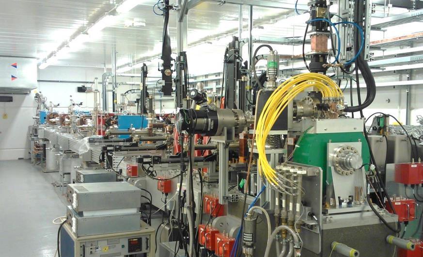
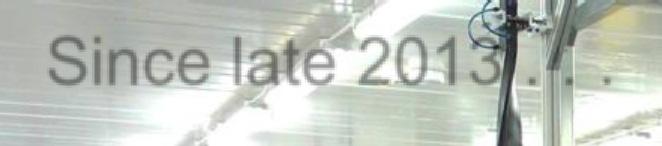
4 VELA and CLARA at Daresbury STFC Daresbury Laboratory STFC Rutherford Appleton Laboratory LONDON VELA SRS decomissioned in 2008 Since late VELA ~ 20m 4
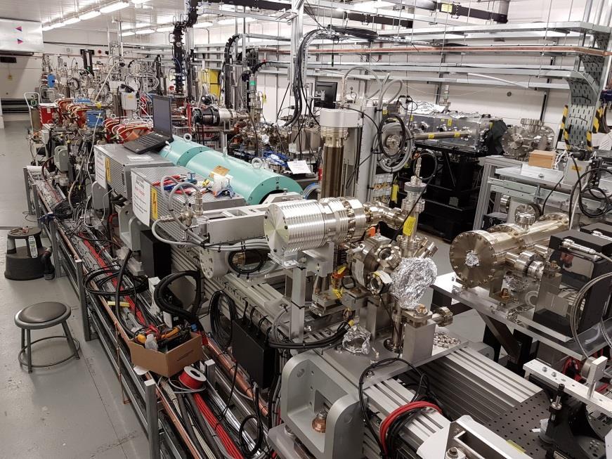
5 Versatile Electron Linear Accelerator (VELA) High quality, pulsed electron beam source. Ultra-short pulses, highly stable (position, time, energy etc.), excellent diagnostics, customisable beams. Two large, flexible, fully shielded experimental areas (BA1 and BA2). Easy access for industry and academia. Can access both sides of the wall. High performance capability of VELA used to explore fundamental delivery capabilities of future compact FEL sources (CLARA). 5
6 Versatile Electron Linear Accelerator (VELA) High quality, pulsed electron beam source. Ultra-short pulses, highly stable (position, time, energy etc.), excellent diagnostics, customisable beams. Two large, flexible, fully shielded experimental areas (BA1 and BA2). Easy access for industry and academia. Can access both sides of the wall. High performance capability of VELA used to explore fundamental delivery capabilities of future compact FEL sources (CLARA). Target Machine Specification Beam Energy 4 6 MeV (50 MeV with CLARA-FE) Bunch Charge pc Bunch length (σ t,rms ) ps Normalised emittance 1 4 μm Beam size (σ x,y,rms ) mm Energy spread (σ e,rms ) 1 5 % Bunch repetition rate 1 10 Hz (400 Hz with CLARA-FE) *Not all parameters achievable simultaneously 6
. Easy access for industry and academia. Can access both sides of the wall.")
7 Versatile Electron Linear Accelerator (VELA) High quality, pulsed electron beam source. Ultra-short pulses, highly stable (position, time, energy etc.), excellent diagnostics, customisable beams. Two large, flexible, fully shielded experimental areas (BA1 and BA2). Easy access for industry and academia. Can access both sides of the wall. High performance capability of VELA used to explore fundamental delivery capabilities of future compact FEL sources (CLARA). Target Machine Specification VELA Injector and Diagnostics Line 4 6 MeV Beam Energy (50 MeV with CLARA-FE) Bunch Charge pc Bunch length (σ t,rms ) ps Normalised emittance 1 4 μm Beam size (σ x,y,rms ) mm Energy spread (σ e,rms ) 1 5 % Bunch repetition rate 1 10 Hz (400 Hz with CLARA-FE) *Not all parameters achievable simultaneously 7


8 VELA 10 Hz Photocathode RF Gun Technology Photo-injector Parameters NC RF VELA photocathode gun Operation frequency, MHz Cavity design 2.5 cell Maximum Repetition Rate, Hz 10 Maximum cathode field, MV/m 100 Maximum beam energy, MeV 6.5 Maximum RF pulsed power, MW 10 Copper photocathode integrated into the gun as back wall of the cavity, with Qe of 10-5 measured. Maximum RF pulse duration, μs 3 Maximum RF pulse repetition rate, Hz 10 Photocathode technology Metal copper Maximum bunch charge, pc 250 Beam emittance at maximum bunch charge, mm mrad 2 ALPHA-X Gun on loan from Strathclyde Univ. 8
9 Compact Linear Accelerator for Research and Applications (CLARA) UK-FEL Test facility: Capable of testing new FEL techniques. Taking FELs into new regime. Address many scientific and technology challenges for future large scale UK-FEL facility: Shorter Pulses Improved Temporal Coherence Tailored Pulse Structures Stability & Power Key technologies: New photo-injector technologies Novel undulators (short period, superconducting.) New accelerating structures: X-Band etc... Advanced single bunch diagnostics. 9
10 VELA and CLARA 10
11 VELA and CLARA 11
12 VELA and CLARA 12
13 VELA and CLARA 13
14 VELA and CLARA 14
 25 25 16 Nominal RF power (MW) 30 37 6 Maximum RF power (MW) 41 57 29 Operating Mode 2π/3 2π/3 5π/6 Repetition rate (Hz) 400")
 ~12000 ~15000 Shunt Impedance (MΩ/m) 54 62 68 Nominal operating temp.")
15 VELA and CLARA X-band option Linac 1 Linac th Harmonic Number of cells Frequency (MHz) Nominal RF voltage (MV/m) Maximum RF voltage (MV/m) Nominal RF power (MW) Maximum RF power (MW) Operating Mode 2π/3 2π/3 5π/6 Repetition rate (Hz) Filling time (μs) Length Flange to Flange (m) Active Length (m) Quality Factor (Q o ) ~12000 ~15000 Shunt Impedance (MΩ/m) Nominal operating temp. (ºC) ~30 ~35 ~35 2 m S-Band Linac manufactured by Research Instruments 3 x 4 m S-Band Linacs provided by PSI 15

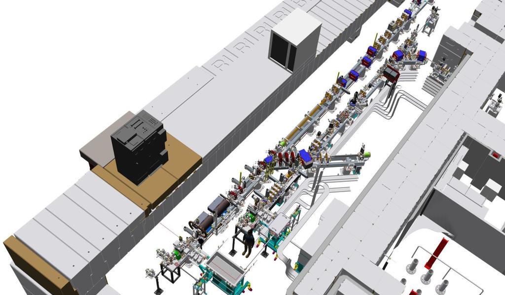

16 Compact Linear Accelerator for Research and Applications CLARA build Phase /16 16
17 17 C L A R A CLARA build Phase /19 17


18 Compact Linear Advanced Research Accelerator 18

19 VELA Commissioning Bunch charges from 40 fc (for ED) to 250 pc with peak beam energy of ~5 MeV are reliably achieved. Dark current, measured with two different cathodes, has shown continual improvement: Decreasing from 1.2 nc to 130 pc per 3 μs RF pulse at 70 MV/m. Long. and Trans. beam qualities characterised through, slit, quad. scans, spectrometer line and TDC measurements. Micron level beam emittance 10 pc. 19
20 VELA TDC Characterisation 20

 - smaller samples needed, Lower energy transfer per scattering event -")
21 Electron Diffraction on VELA Electron Diffraction enables ultrafast structural analysis of materials. At a few MeV, able to minimise space charge limitations to obtain short bunches with sufficient charge, to enable high quality diffraction data in a single shot on VELA: Complements structural dynamics and fs crystallography with X-ray FELs. ED advantages: Higher scattering cross sections for electrons than X-rays (> 10 4 ) - smaller samples needed, Lower energy transfer per scattering event - less sample damage, Smaller and cheaper multi-mev accelerators, as opposed to multi-gev accelerators for X-ray FELs. 21


22 Electron Diffraction Sample Chamber System on VELA allows single shot ED patterns to be obtained with sub-pc bunches from a variety of simple metals and semiconductors. Single gold crystal ED pattern using single 40 fc VELA electron bunch a: incident electron beam, b: shaping apertures c: sample carousel, d: screen e: mounts for focussing optics for laser pump (future programme) f: diffracted beams 22


23 Time-of-Flight Backscatter Security Scanning Scintillator Detector Compton Photon X-ray Sample Single plane source & detector Utilising ToF information to create 3D X-Ray Compton Scatter Imaging. Relationship between the Compton scatter interaction and the photoelectric interaction: Amplitude of the returning compton photon represents the density of the material interacted with, its time response identifies its position. Allows for the development of a cargo security scanner which can reconstruct 3D images using a scanner and detector mounted on only one side of the container. 23
: Long pulse X-Rays blurs")


24 ToF X-Ray Source Requirements Pulsed X-Rays with a very short pulse width (picoseconds): Long pulse X-Rays blurs the timing information and reduces depth of resolution. Collimated source to provide pencil beam geometry: Original trajectory to be accurately known. High energy required to penetrate densely packed cargo for security screening. Readout electronics with high sampling rate: Accurately record the arrival time of each detected photon. Samples Detector Collimator 24
25 Preliminary Detector Characterisation Results Timing Position Amplitude Density Ability to determine sample position via photon ToF proven over several metres of air with a 10 Hz, 4.5 MeV VELA E-Beam. Some indication of material determination further analysis required to improve background suppression and normalisation: Data also collected for single and multiple test pieces. Next step to incorporate multiple detectors and perform first 3D imaging and resolution assessment/refinement. 25


26 New VELA Beam Area 1 Capability New BA1 multi-user facility commissioned using ~4 MeV beams from the 10 Hz VELA RF gun in Sept Beam Sources: New High Repetition Rate Gun (HRRG): ~4 MeV, >ps long bunches at up to 400 Hz. New CLARA-FE ~50 MeV, compressed in CLARA - VELA dog-leg, sub-ps at 10 Hz. bunch lengths down to 300 fs RMS transverse beam sizes of <100 μm RMS at the BA1 interaction point. High power 802 nm, 16 TW peak power laser, 50 fs pulse duration, 0.8 J pulse 10 Hz can also be delivered to the BA1 chamber: Novel acceleration: LWFA or electron beam modulation experiments possible. See poster: S. Jamison, MOOP019 26
 Parameter Unit Beam")


27 CLARA Design JINST 9 (2014) T05001 V9 Lattice (Mar16) Parameter Unit Beam Mode Short Long U.Sh. Flat Energy MeV t FWHM fs Charge pc Slice fs I peak A N target μm N max μm target kev max kev E. Chirp MeV/ps n/a n/a n/a < 1 E. Var. kev n/a n/a n/a <
28 CLARA High Repetition Rate Gun Designed in collaboration with: Lancaster University, UK Institute of Nuclear Research, Moscow CLARA requirements: Hz Hz Interchangeable copper photocathode illuminated by UV laser. CLARA stability requires: 0.1% rms amplitude 0.1 o rms phase Necessitates <0.01 o C rms temperature regulation! Parameter Value Frequency (MHz) Number of Cells 1.5 Q Factor >14000 Maximum Repetition Rate (Hz) 400 Maximum Surface Field (MV/m) 120 Average RF Power (kw) 6.8 Photocathode system development support from: CERN, INFN-LASA (Milano), DESY (Hamburg and Zeuthen) & LBNL 28

 2998.")
 400 Maximum Surface Field (MV/m) 120 Average RF Power")
29 CLARA High Repetition Rate Gun Designed in collaboration with: Lancaster University, UK Institute of Nuclear Research, Moscow CLARA requirements: Hz Hz Interchangeable copper photocathode illuminated by UV laser. CLARA stability requires: 0.1% rms amplitude 0.1 o rms phase Necessitates <0.01 o C rms temperature regulation! Parameter Value Frequency (MHz) Number of Cells 1.5 Q Factor >14000 Maximum Repetition Rate (Hz) 400 Maximum Surface Field (MV/m) 120 Average RF Power (kw) 6.8 Photocathode system development support from: CERN, INFN-LASA (Milano), DESY (Hamburg and Zeuthen) & LBNL 29


30 HRRG Thermal Stability Cavity incorporates 9 separate cooling circuits: Each circuit optimised for expected localised thermal loads. Maximise cooling at RF probe interface. Simulations utilised: CST Microwave Studio E-M Fields ANSYS CFX Fluid dynamics ANSYS Workbench Displacements, frequency shifts and material stress due to RF heating. Largest relative temperature rise of +14 o C predicted at RF probe interface. Average power of 6.8 kw for Hz. Cavity manufactured by Research Instruments. Operating frequency confirmed at 48 o C with field flatness of 98 % ± 1%. Cooling Channel Pressure Temperature Profile Radial Cell Deformation See posters: B.L. Militsyn, MUPLR016 L. Cowie, TUPRC017 30


31 31 CLARA FEL Research Priorities Early stage demonstrations: Single spike SASE: Ultra-short bunches 2-colour Operation: Tune undulators for dual s. Tapering: At long s, early undulator saturation occurs, Tapering undulator field post saturation, significantly increased power can be achieved. Primary demonstrations: Mode locking High Brightness SASE Mode-locked Afterburner 31
 HHRG beam (up to 400 Hz repetition rate), High energy (~50 MeV) CLARA-FE beam (10 Hz repetition rate).")
32 VELA & CLARA Future Plans CLARA-FE installation expected complete by Jan 17. HRRG commissioning on the VELA beamline will start. Once commissioned, possible to provide VELA with: Low energy (4 5 MeV) HHRG beam (up to 400 Hz repetition rate), High energy (~50 MeV) CLARA-FE beam (10 Hz repetition rate). Beam characterisation and R&D to establish the design parameters for CLARA will continue alongside some dedicated allocation time for exploitation programme. Swapping the RF guns possible in early 2018: With the HRRG gun installed on the CLARA-FE, it will then be possible to meet CLARA specifications of 100 Hz repetition rate and at the same time provide higher beam power to the VELA beam areas. CLARA Phase-2 modules ready for commissioning in late First FEL lasing on CLARA by end of VELA Trans National Access included in H2020 ARIES Programme starts 2017! 32


33 Collaborators

34 THANK YOU
VELA/CLARA as Advanced Accelerator Studies Test-bed at Daresbury Lab.
 VELA/CLARA as Advanced Accelerator Studies Test-bed at Daresbury Lab. Yuri Saveliev on behalf of VELA and CLARA teams STFC, ASTeC, Cockcroft Institute Daresbury Lab., UK Outline VELA (Versatile Electron
Diagnostic Systems for Characterizing Electron Sources at the Photo Injector Test Facility at DESY, Zeuthen site
 1 Diagnostic Systems for Characterizing Electron Sources at the Photo Injector Test Facility at DESY, Zeuthen site Sakhorn Rimjaem (on behalf of the PITZ team) Motivation Photo Injector Test Facility at
4GLS Status. Susan L Smith ASTeC Daresbury Laboratory
 4GLS Status Susan L Smith ASTeC Daresbury Laboratory Contents ERLP Introduction Status (Kit on site ) Plan 4GLS (Conceptual Design) Concept Beam transport Injectors SC RF FELs Combining Sources May 2006
Simulations of the IR/THz Options at PITZ (High-gain FEL and CTR)
") Case Study of IR/THz source for Pump-Probe Experiment at the European XFEL Simulations of the IR/THz Options at PITZ (High-gain FEL and CTR) Introduction Outline Simulations of High-gain FEL (SASE) Simulation
Case Study of IR/THz source for Pump-Probe Experiment at the European XFEL Simulations of the IR/THz Options at PITZ (High-gain FEL and CTR) Introduction Outline Simulations of High-gain FEL (SASE) Simulation
Generation and characterization of ultra-short electron and x-ray x pulses
 Generation and characterization of ultra-short electron and x-ray x pulses Zhirong Huang (SLAC) Compact XFEL workshop July 19-20, 2010, Shanghai, China Ultra-bright Promise of XFELs Ultra-fast LCLS Methods
Photo Injector Test facility at DESY, Zeuthen site
 Photo Injector Test facility at DESY, Zeuthen site PITZ EXPERIENCE ON THE EXPERIMENTAL OPTIMIZATION OF THE RF PHOTO INJECTOR FOR THE EUROPEAN XFEL Mikhail Krasilnikov (DESY) for the PITZ Team FEL 2013
Low slice emittance preservation during bunch compression
 Low slice emittance preservation during bunch compression S. Bettoni M. Aiba, B. Beutner, M. Pedrozzi, E. Prat, S. Reiche, T. Schietinger Outline. Introduction. Experimental studies a. Measurement procedure
Experimental Optimization of Electron Beams for Generating THz CTR and CDR with PITZ
 Experimental Optimization of Electron Beams for Generating THz CTR and CDR with PITZ Introduction Outline Optimization of Electron Beams Calculations of CTR/CDR Pulse Energy Summary & Outlook Prach Boonpornprasert
Short Pulse, Low charge Operation of the LCLS. Josef Frisch for the LCLS Commissioning Team
 Short Pulse, Low charge Operation of the LCLS Josef Frisch for the LCLS Commissioning Team 1 Normal LCLS Parameters First Lasing in April 10, 2009 Beam to AMO experiment August 18 2009. Expect first user
X-ray Free-electron Lasers
 X-ray Free-electron Lasers Ultra-fast Dynamic Imaging of Matter II Ischia, Italy, 4/30-5/3/ 2009 Claudio Pellegrini UCLA Department of Physics and Astronomy Outline 1. Present status of X-ray free-electron
Linac optimisation for the New Light Source
 Linac optimisation for the New Light Source NLS source requirements Electron beam requirements for seeded cascade harmonic generation LINAC optimisation (2BC vs 3 BC) CSR issues energy chirp issues jitter
Expected properties of the radiation from VUV-FEL / femtosecond mode of operation / E.L. Saldin, E.A. Schneidmiller, M.V. Yurkov
 Expected properties of the radiation from VUV-FEL / femtosecond mode of operation / E.L. Saldin, E.A. Schneidmiller, M.V. Yurkov TESLA Collaboration Meeting, September 6-8, 2004 Experience from TTF FEL,
Status of Proof-of-Principle Experiment of Coherent Electron Cooling at BNL
 Status of Proof-of-Principle Experiment of Coherent Electron Cooling at BNL Outline 2 Why we doing it? What is Coherent electron Cooling System description Subsystem performance Plan for Run 18 e-n Luminosity
LOLA: Past, present and future operation
 LOLA: Past, present and future operation FLASH Seminar 1/2/29 Christopher Gerth, DESY 8/5/29 FLASH Seminar Christopher Gerth 1 Outline Past Present Future 8/5/29 FLASH Seminar Christopher Gerth 2 Past
FLASH/DESY, Hamburg. Jörg Rossbach University of Hamburg & DESY, Germany - For the FLASH Team -
 First Lasing below 7nm Wavelength at FLASH/DESY, Hamburg Jörg Rossbach University of Hamburg & DESY, Germany - For the FLASH Team - email: joerg.rossbach@desy.de FLASH: The first FEL user facility for
Femto-second FEL Generation with Very Low Charge at LCLS
 Femto-second FEL Generation with Very Low Charge at LCLS Yuantao Ding, For the LCLS commissioning team X-ray Science at the Femtosecond to Attosecond Frontier workshop May 18-20, 2009, UCLA SLAC-PUB-13525;
Commissioning of the new Injector Laser System for the Short Pulse Project at FLASH
 Commissioning of the new Injector Laser System for the Short Pulse Project at FLASH Uni Hamburg tim.plath@desy.de 05.11.2013 Supported by BMBF under contract 05K10GU2 & FS FLASH 301 Motivation short pulses
FEL R&D goals and potential in UK Institutes
 FEL R&D goals and potential in UK Institutes Brian McNeil, Department of Physics, University of Strathclyde For: Peter Ratoff, Director, Cockcroft Institute, Daresbury Laboratory UK-XFEL R&D goals Critically
Simulations of the IR/THz source at PITZ (SASE FEL and CTR)
") Simulations of the IR/THz source at PITZ (SASE FEL and CTR) Introduction Outline Simulations of SASE FEL Simulations of CTR Summary Issues for Discussion Mini-Workshop on THz Option at PITZ DESY, Zeuthen
Simulations of the IR/THz source at PITZ (SASE FEL and CTR) Introduction Outline Simulations of SASE FEL Simulations of CTR Summary Issues for Discussion Mini-Workshop on THz Option at PITZ DESY, Zeuthen
Free-electron laser SACLA and its basic. Yuji Otake, on behalf of the members of XFEL R&D division RIKEN SPring-8 Center
 Free-electron laser SACLA and its basic Yuji Otake, on behalf of the members of XFEL R&D division RIKEN SPring-8 Center Light and Its Wavelength, Sizes of Material Virus Mosquito Protein Bacteria Atom
LCLS Injector Prototyping at the GTF
 LCLS Injector Prototyping at at the GTF John John Schmerge, SLAC SLAC November 3, 3, 23 23 GTF GTF Description Summary of of Previous Measurements Longitudinal Emittance Transverse Emittance Active LCLS
SRF GUN CHARACTERIZATION - PHASE SPACE AND DARK CURRENT MEASUREMENTS AT ELBE*
 SRF GUN CHARACTERIZATION - PHASE SPACE AND DARK CURRENT MEASUREMENTS AT ELBE* E. Panofski #, A. Jankowiak, T. Kamps, Helmholtz-Zentrum Berlin, Berlin, Germany P.N. Lu, J. Teichert, Helmholtz-Zentrum Dresden-Rossendorf,
The New Superconducting RF Photoinjector a High-Average Current & High-Brightness Gun
 The New Superconducting RF Photoinjector a High-Average Current & High-Brightness Gun Jochen Teichert for the BESSY-DESY-FZD-MBI collaboration and the ELBE crew High-Power Workshop, UCLA, Los Angeles 14
PAL LINAC UPGRADE FOR A 1-3 Å XFEL
 PAL LINAC UPGRADE FOR A 1-3 Å XFEL J. S. Oh, W. Namkung, Pohang Accelerator Laboratory, POSTECH, Pohang 790-784, Korea Y. Kim, Deutsches Elektronen-Synchrotron DESY, D-603 Hamburg, Germany Abstract With
ASTRA simulations of the slice longitudinal momentum spread along the beamline for PITZ
 ASTRA simulations of the slice longitudinal momentum spread along the beamline for PITZ Orlova Ksenia Lomonosov Moscow State University GSP-, Leninskie Gory, Moscow, 11999, Russian Federation Email: ks13orl@list.ru
Jlab FEL Photoemission DC Guns
 Jlab FEL Photoemission DC Guns Fay Hannon On behalf of the FEL team FLS 2010, 2 nd March 2 Operational Guns 1. FEL Gun 60m Gun Test Stand (GTS) 2. Backup gun, test stand with beam characterization beamline
Accelerator Activities at PITZ
 Accelerator Activities at PITZ Plasma acceleration etc. Outline > Motivation / Accelerator Research & Development (ARD) > Plasma acceleration Basic Principles Activities SINBAD > ps-fs electron and photon
SCSS Prototype Accelerator -- Its outline and achieved beam performance --
 SCSS Prototype Accelerator -- Its outline and achieved beam performance -- Hitoshi TANAKA RIKEN, XFEL Project Office 1 Content 1. Light Quality; SPring-8 v.s. XFEL 2. What are the critical issues? 3. Mission
SwissFEL INJECTOR DESIGN: AN AUTOMATIC PROCEDURE
 Proceedings of FEL03, New York, NY, USA SwissFEL INJECTOR DESIGN: AN AUTOMATIC PROCEDURE S. Bettoni, M. Pedrozzi, S. Reiche, PSI, Villigen, Switzerland Abstract The first section of FEL injectors driven
The MID instrument.
 The MID instrument International Workshop on the Materials Imaging and Dynamics Instrument at the European XFEL Grenoble, Oct 28/29, 2009 Thomas Tschentscher thomas.tschentscher@xfel.eu Outline 2 History
Flexible control of femtosecond pulse duration and separation using an emittance-spoiling foil in x-ray free-electron lasers
 SLAC PUB 16312 June 2015 Flexible control of femtosecond pulse duration and separation using an emittance-spoiling foil in x-ray free-electron lasers Y. Ding 1, C. Behrens 2, R. Coffee 1, F.-J. Decker
Dielectric Accelerators at CLARA. G. Burt, Lancaster University On behalf of ASTeC, Lancaster U., Liverpool U., U. Manchester, and Oxford U.
 Dielectric Accelerators at CLARA G. Burt, Lancaster University On behalf of ASTeC, Lancaster U., Liverpool U., U. Manchester, and Oxford U. Dielectric Accelerators Types Photonic structures Dielectric
SPARCLAB. Source For Plasma Accelerators and Radiation Compton. On behalf of SPARCLAB collaboration
 SPARCLAB Source For Plasma Accelerators and Radiation Compton with Laser And Beam On behalf of SPARCLAB collaboration EMITTANCE X X X X X X X X 2 BRIGHTNESS (electrons) B n 2I nx ny A m 2 rad 2 The current
SPARCLAB. Source For Plasma Accelerators and Radiation Compton with Laser And Beam
 SPARCLAB Source For Plasma Accelerators and Radiation Compton with Laser And Beam EMITTANCE X X X X X X X X Introduction to SPARC_LAB 2 BRIGHTNESS (electrons) B n 2I nx ny A m 2 rad 2 The current can be
Introduction. Thermoionic gun vs RF photo gun Magnetic compression vs Velocity bunching. Probe beam design options
 Introduction Following the 19/05/04 meeting at CERN about the "CTF3 accelerated programme", a possible french contribution has been envisaged to the 200 MeV Probe Beam Linac Two machine options were suggested,
First propositions of a lattice for the future upgrade of SOLEIL. A. Nadji On behalf of the Accelerators and Engineering Division
 First propositions of a lattice for the future upgrade of SOLEIL A. Nadji On behalf of the Accelerators and Engineering Division 1 SOLEIL : A 3 rd generation synchrotron light source 29 beamlines operational
New Electron Source for Energy Recovery Linacs
 New Electron Source for Energy Recovery Linacs Ivan Bazarov 20m Cornell s photoinjector: world s brightest electron source 1 Outline Uses of high brightness electron beams Physics of brightness High brightness
The European XFEL in Hamburg: Status and beamlines design
 UVX 2010 (2011) 63 67 DOI: 10.1051/uvx/2011009 C Owned by the authors, published by EDP Sciences, 2011 The European XFEL in Hamburg: Status and beamlines design J. Gaudin, H. Sinn and Th. Tschentscher
Time resolved transverse and longitudinal phase space measurements at the high brightness photo injector PITZ
 Time resolved transverse and longitudinal phase space measurements at the high brightness photo injector PITZ 1. Motivation 2. Transverse deflecting structure 3. Longitudinal phase space tomography 4.
START-TO-END SIMULATIONS FOR IR/THZ UNDULATOR RADIATION AT PITZ
 Proceedings of FEL2014, Basel, Switzerland MOP055 START-TO-END SIMULATIONS FOR IR/THZ UNDULATOR RADIATION AT PITZ P. Boonpornprasert, M. Khojoyan, M. Krasilnikov, F. Stephan, DESY, Zeuthen, Germany B.
Beam Echo Effect for Generation of Short Wavelength Radiation
 Beam Echo Effect for Generation of Short Wavelength Radiation G. Stupakov SLAC NAL, Stanford, CA 94309 31st International FEL Conference 2009 Liverpool, UK, August 23-28, 2009 1/31 Outline of the talk
Linac Based Photon Sources: XFELS. Coherence Properties. J. B. Hastings. Stanford Linear Accelerator Center
 Linac Based Photon Sources: XFELS Coherence Properties J. B. Hastings Stanford Linear Accelerator Center Coherent Synchrotron Radiation Coherent Synchrotron Radiation coherent power N 6 10 9 incoherent
An Overview of the Activities of ICS Sources in China
 An Overview of the Activities of ICS Sources in China Chuanxiang Tang *, Yingchao Du, Wenhui Huang * tang.xuh@tsinghua.edu.cn Department of Engineering physics, Tsinghua University, Beijing 100084, China
Development of Cs 2 Te photocathode RF gun system for compact THz SASE-FEL
 Development of Cs 2 Te photocathode RF gun system for compact THz SASE-FEL R. Kuroda, H. Ogawa, N. Sei, H. Toyokawa, K. Yagi-Watanabe, M. Yasumoto, M. Koike, K. Yamada, T. Yanagida*, T. Nakajyo*, F. Sakai*
Linac Driven Free Electron Lasers (III)
") Linac Driven Free Electron Lasers (III) Massimo.Ferrario@lnf.infn.it SASE FEL Electron Beam Requirements: High Brightness B n ( ) 1+ K 2 2 " MIN r #$ % &B! B n 2 n K 2 minimum radiation wavelength energy
Linac Driven Free Electron Lasers (III) Massimo.Ferrario@lnf.infn.it SASE FEL Electron Beam Requirements: High Brightness B n ( ) 1+ K 2 2 " MIN r #$ % &B! B n 2 n K 2 minimum radiation wavelength energy
Dark Current at Injector. Jang-Hui Han 27 November 2006 XFEL Beam Dynamics Meeting
 Dark Current at Injector Jang-Hui Han 27 November 2006 XFEL Beam Dynamics Meeting Considerations for the guns Ultra-low slice emittance of electron beams higher gradient at the gun cavity solenoid field
X-band Experience at FEL
 X-band Experience at FERMI@Elettra FEL Gerardo D Auria Elettra - Sincrotrone Trieste GdA_TIARA Workshop, Ångström Laboratory, June 17-19, 2013 1 Outline The FERMI@Elettra FEL project Machine layout and
LCLS Commissioning Status
 LCLS Commissioning Status Paul Emma (for the LCLS Commissioning Team) June 20, 2008 LCLS ANL LLNL UCLA FEL Principles Electrons slip behind EM wave by λ 1 per undulator period ( (λ u ) x K/γ e λ u v x
LCLS-II SCRF start-to-end simulations and global optimization as of September Abstract
 SLAC National Accelerator Lab LCLS-II TN-17-4 February 217 LCLS-II SCRF start-to-end simulations and global optimization as of September 216 G. Marcus SLAC, Menlo Park, CA 9425 J. Qiang LBNL, Berkeley,
An Adventure in Marrying Laser Arts and Accelerator Technologies
 An Adventure in Marrying Laser Arts and Accelerator Technologies Dao Xiang Beam Physics Dept, SLAC, Stanford University Feb-28-2012 An example sample Probe (electron) Pump (laser) Typical pump-probe experiment
AREAL Test Facility for Advanced Accelerator and Radiation Sources Concepts
 2 nd European Advanced Accelerator Concepts AREAL Test Facility for Advanced Accelerator and Radiation Sources Concepts V. Tsakanov CANDLE SRI 13-19 Sep 2015, La Biodola, Isola d'elba Introduction 2nd
Introduction to the benchmark problem
 Introduction to the benchmark problem M. Krasilnikov (DESY) Working group 4: Low emittance electron guns 37th ICFA Beam Dynamics Workshop Future Light Sources 15 19 May 6 DESY, Hamburg, Germany Outline
Undulator radiation from electrons randomly distributed in a bunch
 Undulator radiation from electrons randomly distributed in a bunch Normally z el >> N u 1 Chaotic light Spectral property is the same as that of a single electron /=1/N u Temporal phase space area z ~(/
Photoinjectors and Photocathode Activity at Daresbury Laboratory
 Photoinjectors and Photocathode Activity at Daresbury Laboratory Tim Noakes Accelerator Physics Group, ASTeC STFC Daresbury Laboratory DL Accelerators CLARA Proposed FEL test facility VELA RF gun and electron
Studies with Ultra-Short Pulses
 Studies with Ultra-Short Pulses E. Hass, A. Kuhl, T. Plath, M. Rehders, J. Rönsch-Schulenburg, J. Rossbach, V. Wacker: Universität Hamburg, Institut für Experimentalphysik; N.-I. Baboi, M. Bousonville,
DIAGNOSTIC TEST-BEAM-LINE FOR THE MESA INJECTOR
 DIAGNOSTIC TEST-BEAM-LINE FOR THE MESA INJECTOR I.Alexander,K.Aulenbacher,V.Bechthold,B.Ledroit,C.Matejcek InstitutfürKernphysik,JohannesGutenberg-Universität,D-55099Mainz,Germany Abstract With the test-beam-line
What have we learned from the LCLS injector?*
 SLAC-PUB-14644 LCLS-TN-11-4 October 19, 2011 What have we learned from the LCLS injector?* Feng Zhou and Axel Brachmann for the LCLS injector team The LCLS injector reliably delivered a high quality electron
WG2 on ERL light sources CHESS & LEPP
 Charge: WG2 on ERL light sources Address and try to answer a list of critical questions for ERL light sources. Session leaders can approach each question by means of (a) (Very) short presentations (b)
Echo-Enabled Harmonic Generation
 Echo-Enabled Harmonic Generation G. Stupakov SLAC NAL, Stanford, CA 94309 IPAC 10, Kyoto, Japan, May 23-28, 2010 1/29 Outline of the talk Generation of microbunching in the beam using the echo effect mechanism
Layout of the HHG seeding experiment at FLASH
 Layout of the HHG seeding experiment at FLASH V. Miltchev on behalf of the sflash team: A. Azima, J. Bödewadt, H. Delsim-Hashemi, M. Drescher, S. Düsterer, J. Feldhaus, R. Ischebeck, S. Khan, T. Laarmann
Developments for the FEL user facility
 Developments for the FEL user facility J. Feldhaus HASYLAB at DESY, Hamburg, Germany Design and construction has started for the FEL user facility including the radiation transport to the experimental
DESIGN AND CONSTRUCTION OF LOW ENERGY ELECTRON ACCELERATORS AT SINP MSU
 DESIGN AND CONSTRUCTION OF LOW ENERGY ELECTRON ACCELERATORS AT SINP MSU V. Shvedunov Skobeltsyn Institute of Nuclear Physics Lomonosov Moscow State University 26 November 2013 Betatron 1959-1985 Low intensity
Harmonic Lasing Self-Seeded FEL
 Harmonic Lasing Self-Seeded FEL E. Schneidmiller and M. Yurkov FEL seminar, DESY Hamburg June 21, 2016 In a planar undulator (K ~ 1 or K >1) the odd harmonics can be radiated on-axis (widely used in SR
Excitements and Challenges for Future Light Sources Based on X-Ray FELs
 Excitements and Challenges for Future Light Sources Based on X-Ray FELs 26th ADVANCED ICFA BEAM DYNAMICS WORKSHOP ON NANOMETRE-SIZE COLLIDING BEAMS Kwang-Je Kim Argonne National Laboratory and The University
4 FEL Physics. Technical Synopsis
 4 FEL Physics Technical Synopsis This chapter presents an introduction to the Free Electron Laser (FEL) physics and the general requirements on the electron beam parameters in order to support FEL lasing
Accelerators and Lasers In Combined Experiments Susan Smith Daresbury Laboratory
 ALICE iagnostics Accelerators and Lasers In Combined Experiments Susan Smith aresbury Laboratory Contents Quick Review of ALICE iagnostics Extended injector line ALICE to EMMA transfer line EMMA ebpm Other
FURTHER UNDERSTANDING THE LCLS INJECTOR EMITTANCE*
 Proceedings of FEL014, Basel, Switzerland FURTHER UNDERSTANDING THE LCLS INJECTOR EMITTANCE* F. Zhou, K. Bane, Y. Ding, Z. Huang, and H. Loos, SLAC, Menlo Park, CA 9405, USA Abstract Coherent optical transition
FEL SIMULATION AND PERFORMANCE STUDIES FOR LCLS-II
 FEL SIMULATION AND PERFORMANCE STUDIES FOR LCLS-II G. Marcus, Y. Ding, P. Emma, Z. Huang, T. Raubenheimer, L. Wang, J. Wu SLAC, Menlo Park, CA 9, USA Abstract The design and performance of the LCLS-II
A Review of ERL Prototype Experience and Light Source Design Challenges. Susan Smith Accelerator Physics ASTeC CCLRC Daresbury Laboratory
 A Review of ERL Prototype Experience and Light Source Design Challenges Susan Smith Accelerator Physics ASTeC CCLRC Daresbury Laboratory Content Existing light source ERLs JLAB experience Challenges of
High average current photo injector (PHIN) for the CLIC Test Facility at CERN
 for the CLIC Test Facility at CERN") High average current photo injector (PHIN) for the CLIC Test Facility at CERN CLIC and CTF3 motivation Photo injectors, PHIN Emittance measurements Long pulse operation, time resolved measurements Cathode
High average current photo injector (PHIN) for the CLIC Test Facility at CERN CLIC and CTF3 motivation Photo injectors, PHIN Emittance measurements Long pulse operation, time resolved measurements Cathode
Accelerator R&D Opportunities: Sources and Linac. Developing expertise. D. Rubin, Cornell University
 Accelerator R&D Opportunities: Sources and Linac D. Rubin, Cornell University Electron and positron sources Requirements Status of R&D Linac Modeling of beam dynamics Development of diagnostic and tuning
Investigations on the electron bunch distribution in the longitudinal phase space at a laser driven RF-electron source for the European X-FEL
 Juliane Rönsch Universität Hamburg / DESY Investigations on the electron bunch distribution in the longitudinal phase space at a laser driven RF-electron source for the European X-FEL 5/27/2009 1 Contents
THE LCLS-II INJECTOR DESIGN*
 THE LCLS-II INJECTOR DESIGN* J.F. Schmerge #, A. Brachmann, D. Dowell, A. Fry, R.K. Li, Z. Li, T. Raubenheimer, T. Vecchione, F. Zhou, SLAC, Menlo Park, CA 94025, USA A. Bartnik, I. Bazarov, B. Dunham,
Vertical Polarization Option for LCLS-II. Abstract
 SLAC National Accelerator Lab LCLS-II TN-5-8 March 5 Vertical Polarization Option for LCLS-II G. Marcus, T. Raubenheimer SLAC, Menlo Park, CA 95 G. Penn LBNL, Berkeley, CA 97 Abstract Vertically polarized
Length of beam system = 910m. S. Reiche X var = ~50m ~ 650m / Y. Kim FEL-KY ~150m. ~60m. LaserHutch2 (access during operation)
") Laser Laser HHG Diagnostic ATHOS PORTHOS ARAMIS THz-Pump P A U L S C H E R R E R I N S T I T U T Length of beam system = 910m &'!( Test & Commissioning steps (A,B,C) A11 Conv. Gun & Injector A12 LINAC
Laser Laser HHG Diagnostic ATHOS PORTHOS ARAMIS THz-Pump P A U L S C H E R R E R I N S T I T U T Length of beam system = 910m &'!( Test & Commissioning steps (A,B,C) A11 Conv. Gun & Injector A12 LINAC
FREE-ELECTRON LASER FACILITY(U) NATIONAL BUREAU OF STANDARDS GAITHERSBURG NO P H DEBENHdAN ET AL UNCLASSIFIED F/G 14/2 NI
 NATIONAL BUREAU OF STANDARDS GAITHERSBURG NO P H DEBENHdAN ET AL UNCLASSIFIED F/G 14/2 NI") -R9 IN1 RESEARCH OPPORTUNITIES BELOWd 398 NN AT THE NOS / FREE-ELECTRON LASER FACILITY(U) NATIONAL BUREAU OF STANDARDS GAITHERSBURG NO P H DEBENHdAN ET AL. 1907 UNCLASSIFIED F/G 14/2 NI 1Z, II"',,-- -.-
-R9 IN1 RESEARCH OPPORTUNITIES BELOWd 398 NN AT THE NOS / FREE-ELECTRON LASER FACILITY(U) NATIONAL BUREAU OF STANDARDS GAITHERSBURG NO P H DEBENHdAN ET AL. 1907 UNCLASSIFIED F/G 14/2 NI 1Z, II"',,-- -.-
Excitements and Challenges for Future Light Sources Based on X-Ray FELs
 Excitements and Challenges for Future Light Sources Based on X-Ray FELs 26th ADVANCED ICFA BEAM DYNAMICS WORKSHOP ON NANOMETRE-SIZE COLLIDING BEAMS Kwang-Je Kim Argonne National Laboratory and The University
Photoinjector design for the LCLS
 SLAC-PUB-8962 LCLS-TN-01-05 Revised November 2001 Photoinjector design for the LCLS P.R. Bolton a, J.E. Clendenin a, D.H. Dowell a, M. Ferrario b, A.S. Fisher a, S.M. Gierman a, R.E. Kirby a, P. Krejcik
AREAL. Test Facility for Advanced Accelerator and Radiation Sources Concepts. Part.1 Introduction. V. Tsakanov CANDLE SRI
 AREAL Test Facility for Advanced Accelerator and Radiation Sources Concepts Part.1 Introduction V. Tsakanov CANDLE SRI 01 October 2015 2 nd European Advanced Accelerator Concepts 13-19 Sep 2015, Isola
Microbunching Workshop 2010 March 24, 2010, Frascati, Italy. Zhirong Huang
 Measurements of the LCLS Laser Heater and its impact on the LCLS FEL Performance Z. Huang for the LCLS commissioning team LCLS 1 1 Outline Introduction LCLS setup and measurements Effects on FEL performance
Injector Experimental Progress
 Injector Experimental Progress LCLS TAC Meeting December 10-11 2001 John Schmerge for the GTF Team GTF Group John Schmerge Paul Bolton Steve Gierman Cecile Limborg Brendan Murphy Dave Dowell Leader Laser
The design for the LCLS rf photo-injector
 SLAC-PUB-8054 January 1999 The design for the LCLS rf photo-injector R. Alley, V. Bharadwaj, J. Clendenin, P. Emma, A. Fisher, J. Frisch, T. Kotseroglou, R. Miller, D. T. Palmer, J. Schmerge, J. C. Sheppard,
S2E (Start-to-End) Simulations for PAL-FEL. Eun-San Kim
 Simulations for PAL-FEL. Eun-San Kim") S2E (Start-to-End) Simulations for PAL-FEL Aug. 25 2008 Kyungpook Nat l Univ. Eun-San Kim 1 Contents I Lattice and layout for a 10 GeV linac II Beam parameters and distributions III Pulse-to-pulse stability
S2E (Start-to-End) Simulations for PAL-FEL Aug. 25 2008 Kyungpook Nat l Univ. Eun-San Kim 1 Contents I Lattice and layout for a 10 GeV linac II Beam parameters and distributions III Pulse-to-pulse stability
Comparison of the APS Upgrade to
 Comparison of the APS Upgrade to ERL@APS Michael Borland Argonne National Laboratory March 2010 The submitted manuscript has been created by UChicago Argonne, LLC, Operator of Argonne National Laboratory
Start-to-End Simulations
 AKBP 9.3 Case Study for 100 µm SASE FEL Based on PITZ Accelerator for Pump-Probe Experiment at the European XFEL Start-to-End Simulations Outline Introduction Beam Optimization Beam Transport Simulation
R&D experiments at BNL to address the associated issues in the Cascading HGHG scheme
 R&D experiments at BNL to address the associated issues in the Cascading HGHG scheme Li Hua Yu for DUV-FEL Team National Synchrotron Light Source Brookhaven National Laboratory FEL2004 Outline The DUVFEL
Simulation of the Beam Dump for a High Intensity Electron gun
 EUROPEAN ORGANIZATION FOR NUCLEAR RESEARCH CERN BEAMS DEPARTMENT CERN-BE-2014-007 BI Simulation of the Beam Dump for a High Intensity Electron gun S. Doebert; T. Lefèvre; A, Jeff; CERN Geneva/CH K. Pepitone
ICFA ERL Workshop Jefferson Laboratory March 19-23, 2005 Working Group 1 summary Ilan Ben-Zvi & Ivan Bazarov
 ICFA ERL Workshop Jefferson Laboratory March 19-23, 2005 Working Group 1 summary Ilan Ben-Zvi & Ivan Bazarov Sincere thanks to all WG1 participants: Largest group, very active participation. This summary
SLS at the Paul Scherrer Institute (PSI), Villigen, Switzerland
, Villigen, Switzerland") SLS at the Paul Scherrer Institute (PSI), Villigen, Switzerland Michael Böge 1 SLS Team at PSI Michael Böge 2 Layout of the SLS Linac, Transferlines Booster Storage Ring (SR) Beamlines and Insertion Devices
SLS at the Paul Scherrer Institute (PSI), Villigen, Switzerland Michael Böge 1 SLS Team at PSI Michael Böge 2 Layout of the SLS Linac, Transferlines Booster Storage Ring (SR) Beamlines and Insertion Devices
CONCEPTUAL STUDY OF A SELF-SEEDING SCHEME AT FLASH2
 CONCEPTUAL STUDY OF A SELF-SEEDING SCHEME AT FLASH2 T. Plath, L. L. Lazzarino, Universität Hamburg, Hamburg, Germany K. E. Hacker, T.U. Dortmund, Dortmund, Germany Abstract We present a conceptual study
SPPS: The SLAC Linac Bunch Compressor and Its Relevance to LCLS
 LCLS Technical Advisory Committee December 10-11, 2001. SPPS: The SLAC Linac Bunch Compressor and Its Relevance to LCLS Patrick Krejcik LCLS Technical Advisory Committee Report 1: July 14-15, 1999 The
Tomographic transverse phase space measurements at PITZ.
 Tomographic transverse phase space measurements at PITZ. > Photo-Injector Test facility at DESY in Zeuthen - PITZ > Tomography in beam diagnostics > Hardware > Measurements & evaluation Georgios Kourkafas,
Development of Soft X-rayX using Laser Compton Scattering
 26 th Advanced ICFA Beam Dynamics Workshop on Nanometre-Size Colliding Beams September 2-6, 2002 at Lausanne Development of Soft X-rayX Source using Laser Compton Scattering R. Kuroda*, S. Kashiwagi*,
X-band RF driven hard X-ray FELs. Yipeng Sun ICFA Workshop on Future Light Sources March 5-9, 2012
 X-band RF driven hard X-ray FELs Yipeng Sun ICFA Workshop on Future Light Sources March 5-9, 2012 Motivations & Contents Motivations Develop more compact (hopefully cheaper) FEL drivers, L S C X-band (successful
Beam Diagnostics and Instrumentation JUAS, Archamps Peter Forck Gesellschaft für Schwerionenforschnung (GSI)
") Beam Diagnostics and Instrumentation JUAS, Archamps Peter Forck Gesellschaft für Schwerionenforschnung (GSI), 2003, A dedicated proton accelerator for 1p-physics at the future GSI Demands facilities for
Beam Diagnostics and Instrumentation JUAS, Archamps Peter Forck Gesellschaft für Schwerionenforschnung (GSI), 2003, A dedicated proton accelerator for 1p-physics at the future GSI Demands facilities for
Hiromitsu TOMIZAWA XFEL Division /SPring-8
 TUPLB10 (Poster: TUPB080) Non-destructive Real-time Monitor to measure 3D- Bunch Charge Distribution with Arrival Timing to maximize 3D-overlapping for HHG-seeded EUV-FEL Hiromitsu TOMIZAWA XFEL Division
FLASH overview. Nikola Stojanovic. PIDID collaboration meeting, Hamburg,
 FLASH overview Nikola Stojanovic PIDID collaboration meeting, Hamburg, 16.12.2011 Outline Overview of the FLASH facility Examples of research at FLASH Nikola Stojanovic PIDID: FLASH overview Hamburg, December
Pushing the limits of laser synchrotron light sources
 Pushing the limits of laser synchrotron light sources Igor Pogorelsky National Synchrotron Light Source 2 Synchrotron light source With λ w ~ several centimeters, attaining XUV region requires electron
Considerations of an Ultrafast Electron Diffraction experiment at
 Considerations of an Ultrafast Electron Diffraction experiment at 04.07.2017 G. Kourkafas, T. Kamps, E. Panofski Yerevan, Armenia Ultrafast Beams and Applications workshop in collaboration with: Max-Born
Experimental Measurements of the ORION Photoinjector Drive Laser Oscillator Subsystem
 Experimental Measurements of the ORION Photoinjector Drive Laser Oscillator Subsystem D.T Palmer and R. Akre Laser Issues for Electron RF Photoinjectors October 23-25, 2002 Stanford Linear Accelerator