4GLS Status. Susan L Smith ASTeC Daresbury Laboratory
|
|
|
- Merry Dalton
- 6 years ago
- Views:
Transcription
1 4GLS Status Susan L Smith ASTeC Daresbury Laboratory
2 Contents ERLP Introduction Status (Kit on site ) Plan 4GLS (Conceptual Design) Concept Beam transport Injectors SC RF FELs Combining Sources May 2006 Susan L Smith 2
3 Introduction to ERLP Energy Recovery Linac Prototype Demonstrating skills and technologies for 4GLS Operation of photo injector electron gun Operation of superconducting electron linac Energy recovery from a FEL-disrupted beam Synchronisation of gun and FEL output May 2006 Susan L Smith 3
4 Main Parameters Nominal Gun Energy 350 kev Injector Energy 8.35 MeV Circulating Beam Energy 35 MeV Linac RF Frequency 1.3 GHz Bunch Repetition Rate MHz Max Bunch Charge 80 pc Max Average Current 13 µa May 2006 Susan L Smith 4

5 May 2006 Susan L Smith 5
 Pulse energy: 80nJ on target Pulse duration: 10ps FWHM Pulse repetition rate: 81 MHz Macropulse duration: 20 ms Duty cycle: 0.")
6 Wavelength: 1.05μm, multiplied to 0.53μm/0.26μm (NdYvanadate) Pulse energy: 80nJ on target Pulse duration: 10ps FWHM Pulse repetition rate: 81 MHz Macropulse duration: 20 ms Duty cycle: 0.2% Timing jitter: <1ps Photoinjector Laser Collaboration with CLF Spatial profile: circular (top hat) on photocathode May 2006 Susan L Smith 6

7 ERLP: Gun electrons JLab GA transverse emittance ~3 mm mrad anode Ceramic having flanges welded, delivery to DL March 06 Pro/E electrons May 2006 Susan L Smith 7


8 Gun Ceramic Manufacture May 2006 Susan L Smith 8

9 Gun Power Supply May 2006 Susan L Smith 9

10 ERLP Cryo system May 2006 Susan L Smith 10
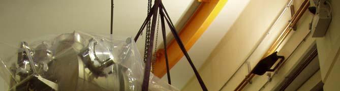
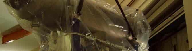
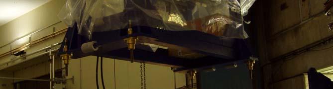
11 Superconducting Booster Module May 2006 Susan L Smith 11
12 ERLP Booster to Linac Transfer Path May 2006 Susan L Smith 12
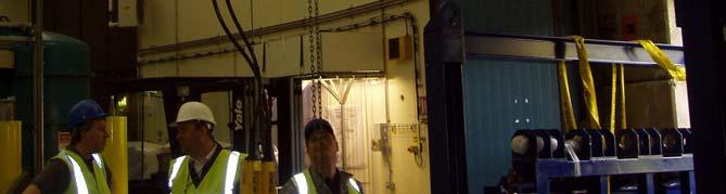
13 Machine Status/Milestones Laser system ready IOTs under test on site Gun ceramic major source of delay at Daresbury (~1 year late) Accelerator modules arrive April/June 2005 (~6 months late) 4 K commissioning May 06 Gun commissioning June-August 06 2K commissioning Sept 06 Complete machine ready October 06 Energy Recovery Spring 07 Exploitation 2007 May 2006 Susan L Smith 13
14 May 2006 Susan L Smith 14
15 Science May 2006 Susan L Smith 15
16 Output May 2006 Susan L Smith 16
17 Key Features THz to soft X-Ray (<1keV) light source Very short pulses (<< 1ps) Combination of pulses for pump-probe experiments Multiple experiments Very small emittance Pulse timing flexibility Electrons not stored continually refreshed Energy recovery linac system Three distinct types of Free Electron Laser Conventional undulators Coherent SR May 2006 Susan L Smith 17
18 4GLS-Three Inter-related accelerators High average current loop ERL, 600 MeV delivering 1.3 GHz = 100 ma Distribute compression giving 1ps 100 fs SR Low Q VUV FEL XUV-FEL Branch 1.5 ka, MeV 1 nc, 1kHz XUV FEL using HHG seed laser scheme IR-FEL MeV SC linac Integrated & synchronised IR-FEL May 2006 Susan L Smith 18
19 Conceptual Layout of 4GLS May 2006 Susan L Smith 19
20 4GLS Beams 600 MeV, 77 pc bunches with short bunch lengths down to ~100 fs RMS, operating at 1.3 GHz for a suite of spontaneous sources or operating at some multiple, n, of 4.33 MHz for a VUV-FEL. The peak current at the VUV- FEL must be over 300 A MeV, 1 nc bunches with peak current >1.5 ka driving an XUV-FEL at 1 khz, with RMS bunch lengths less than 270 fs MeV, 200 pc bunches for an IR-FEL, delivered at 13 MHz with RMS bunch lengths between 1 and 10 ps. May 2006 Susan L Smith 20
21 Challenges Electron Beam Transport Preservation of small emittance Generation of <<ps bunches at the correct locations Minimisation of instabilities (CSR, wakes, ) long bunches! Merge and separation of different beams Minimise losses Collimation 60 MW beam power ILC is 11 MW! 1MW Dump May 2006 Susan L Smith 21
22 CDR Beam Transport Studies Identify possible show stoppers. From defined science case parameters Define concept for accelerator complex capable of broadly delivering science vision Confirm that basic physics driving disruptive processes are understood and parameterised to a degree that confirms that a suitable solution will be tractable during TDR phase Define a clear enough geometry, component list and specification to allow a costing exercise to progress at a basic level of accuracy for the CDR Confirm a target set of beam parameters May 2006 Susan L Smith 22
23 Beam Transport CDR Issues Layout/Concept Modelling of longitudinal gymnastics/compression CSR LSC Wakefield estimates ID wakefield estimates (apertures) BBU limits and understanding of linac focussing issues etc. Ion effect May 2006 Susan L Smith 23
24 FEL Branch Positive phase acceleration Helps to cancel large wakefields from 1nC bunch charge Positive compression (chicane-like) 2-stage BC1/BC2 Spreader R 56 is inherently positive Arc R 56 must be negative - cancels spreader Linac-2 provides final chirp Final bunch compressor provides compression May 2006 Susan L Smith 24
25 XUV-FEL Bunch Parameters Energy 750 to 950 MeV Normalised Emittance RMS Projected Energy Spread at XUV- FEL RMS Bunch Length at XUV-FEL Bunch Charge Bunch Repetition Rate Electron Beam Average Power at XUV- FEL Energy at start of Main Linac (Linac5) 2 mm mrad 0.1% < 270 fs 1 nc 1 khz 1 kw 160 MeV May 2006 Susan L Smith 25
26 CW Branch Bunch must be short in many ID straights separated by arcs Wakefields/apertures limit total straight length where bunch is fully compressed Therefore must have some compression from straight to straight Therefore compression must be negative (arc-like) Therefore negative phase acceleration OK since 77pC bunch has small associated wakefield. Spreader has positive R 56 Loop arc (5xFODO cell) cancels spreader R 56 and performs main compression Final (small) compression performed in 5x TBA cells (6 ID straights) May 2006 Susan L Smith 26
27 High Average Current Bunch Parameter HACL Bunch Parameter 100 ma Operation VUV-FEL Operation Energy at Source 600 MeV 600 MeV Normalised emittance 2 mm mrad 2 mm mrad RMS Projected Energy Spread 0.1 % 0.1 % RMS Bunch Length at Device fs in 6straights 100 fs Bunch Charge 77 pc 77 pc Bunch Repetition Rate 1.3 GHz n x 4.33 MHz Beam Power at 600 MeV 60 MW n x 200 kw Injector Energy 10 MeV ~ 10 MeV Dump Energy ~ 10 MeV ~ 10 MeV May 2006 Susan L Smith 27
28 Progressive Compression Loops + ID VUV-FEL Mode 1: All Short (Probable wakefield limit) Mode 2: Centre Short Mode 3: VUV Short Golden Rule: beam compression (i.e. shear) only goes one way. Beam Propagation May 2006 Susan L Smith 28
29 FEL vs. CW Compression 1 nc 77 pc ~9 FEL and CW Compression are carried out with opposite phases FEL compression requires positive phase/r56 to cancel wakefield effects CW compression requires negative phase/r56 to allow progressive compression in the IDs (TBAs are negative) R 56 >0 R 56 <0 May 2006 Susan L Smith 29
 Rms energy spread No no 97.3 96 0.21% No yes 97.2 104 0.22% yes no 97.0 80 0.")
30 High Average Current Loop Near Start to FEL Simulation Bunch profiles at each of the ID straights, with CSR. CSR LSC Linac phase Rms length (fs) Rms energy spread No no % No yes % yes no % May 2006 Susan L Smith 30
31 Status of XUV-FEL Branch modelling. 2ps 140MeV gaussian beam CSR, LSC in the linacs and straights and wakefields in the linac were included. Phase of the linac had to be changed to allow mainly for the change in energy chirp due to the wakefield and LSC. Without any linearisation from 3rd harmonic cavity or sextupoles included, a peak current of 1.4 ka was obtained, just short of the 1.5 ka target. Further simulations using a more realistic input bunch distribution will be performed in future design work. May 2006 Susan L Smith 31
32 ARCs FEL arc now outside of CW arc SC cavity Solenoids must be 180 degrees apart. Note final compensating bend 14,62 Undulator Advantages: Keeps FEL arc radius large for CSR management Eliminates opposing bends Disadvantages: Vertical offset to transport to pass FEL arc under CW Loop arc 60 cm in present iteration Uses solenoids to achieve vertical matching no flat beams for FEL branch!! Optically complex May 2006 Susan L Smith 32
33 IR FEL Normalised Emittance 10 mm-mrad Projected Energy spread 0.1% RMS Bunch length 1-10 ps Bunch charge 200 pc Bunch rep rate Bunch Repetition Rate 13 MHz Avg. Power 60 MeV 156 kw Branch switching 100 Hz May 2006 Susan L Smith 33
34 BBU Thresholds in the ish ma But we don t have a detailed LINAC cavity design and We have not optimisation of single turn optics Fully explored the linac focussing effects HOM spectrum as for TESLA cavities not modelled skew quadrupoles scheme Etc. May 2006 Susan L Smith 34
35 Injectors 1nC, 1kHz, 2ps, <2 mm mrad 100 ma, 77pC, 1.3 GHz, 2 ps 2 mm mrad 200 pc, 13 MHz, <10 mm mrad, 1-10 ps May 2006 Susan L Smith 35
36 Challenges Photoinjectors 1nC, 1kHz has never been built before Demanding laser Thermal problems from RF losses Other groups are active: BESSY/DESY & LBNL. 77pC, 1.3 GHz (100mA) has never been built before Even more demanding laser DC version has issues with power supply, high voltages SCRF version has issues with photocathodes Other groups are active: Cornell, BNL & JLab.. EUROFeL Activities May 2006 Susan L Smith 36
37 Seven Distinct Superconducting Linac Modules May 2006 Susan L Smith 37
38 Challenges Linacs 7 different SC RF Linacs Based upon 1.3GHz (3.9 GHz 3 rd harmonic) High input powers (10MeV, 100mA = 1MW) Three distinct beams in main linac Complex pulse trains Need to minimise HOMs & extract power at correct temperature Beam Break Up Phase and amplitude control: 0.01, 0.01% - state of the art Need largest ever UK cryogenic plant May 2006 Susan L Smith 38


39 Modified 7 Cell TESLA type Cavity IOT May 2006 Susan L Smith 39


40 Simply 2 x scaled 9-cell TESLA/TTF cavities 100 ma, 10 MeV Booster 3 rd Harmonic May 2006 Susan L Smith 40


 May")
41 3 distinct FEL designs Single pass seeded amplifier (extreme Ultra Violet Seed laser state of the art (HHG system) Undulator tolerances very demanding Low Q cavity (Vacuum Ultra Violet) Mirrors withstand high peak powers High Q cavity (Infra Red) May 2006 Susan L Smith 41
42 4GLS FEL Output May 2006 Susan L Smith 42

43 Combining Sources Three dimensional diagram showing some multibeam stations May 2006 Susan L Smith 43

44 Some details! May 2006 Susan L Smith 44

45 Challenges Timing & Synchronisation All combined sources to have synchronisation better than 100fs Particular combinations require 10fs Many sources of jitter Laser RF signals RF acceleration Electron transport Photon transport May 2006 Susan L Smith 45

46 Present Layout May 2006 Susan L Smith 46

47 External View May 2006 Susan L Smith 47
48 Status & Milestones ERLP Commissioning ( ) Exploitation of ERLP (2007 ) Accelerator science Photon science THz & X-rays (CBS) CDR April TDR March 2007 Costing High priority technical work Prototyping (SC RF, Photoinjector) 3 years Bid for 4GLS funding late 2007 May 2006 Susan L Smith 48


49 Thanks. The 4GLS Team International Advisory Committee May 2006 Susan L Smith 49
A Review of ERL Prototype Experience and Light Source Design Challenges. Susan Smith Accelerator Physics ASTeC CCLRC Daresbury Laboratory
 A Review of ERL Prototype Experience and Light Source Design Challenges Susan Smith Accelerator Physics ASTeC CCLRC Daresbury Laboratory Content Existing light source ERLs JLAB experience Challenges of
Linac optimisation for the New Light Source
 Linac optimisation for the New Light Source NLS source requirements Electron beam requirements for seeded cascade harmonic generation LINAC optimisation (2BC vs 3 BC) CSR issues energy chirp issues jitter
Linacs. Susan Smith. Daresbury Laboratory Mami and Beyond
 Energy Recovery Linacs Susan Smith ASTeC/Cockcroft Daresbury Laboratory Mami and Beyond Introduction to ERLs Contents Operational ERLs Applications Challenges ERL Prototypes and R&D Summary 2 Introduction
WG2 on ERL light sources CHESS & LEPP
 Charge: WG2 on ERL light sources Address and try to answer a list of critical questions for ERL light sources. Session leaders can approach each question by means of (a) (Very) short presentations (b)
Accelerator Physics Issues of ERL Prototype
 Accelerator Physics Issues of ERL Prototype Ivan Bazarov, Geoffrey Krafft Cornell University TJNAF ERL site visit (Mar 7-8, ) Part I (Bazarov). Optics. Space Charge Emittance Compensation in the Injector
Short Pulse, Low charge Operation of the LCLS. Josef Frisch for the LCLS Commissioning Team
 Short Pulse, Low charge Operation of the LCLS Josef Frisch for the LCLS Commissioning Team 1 Normal LCLS Parameters First Lasing in April 10, 2009 Beam to AMO experiment August 18 2009. Expect first user
(M. Bowler, C. Gerth, F. Hannon, H. Owen, B. Shepherd, S. Smith, N. Thompson, E. Wooldridge, N. Wyles)
") Optics considerations for ERL test facilities Bruno Muratori ASTeC Daresbury Laboratory (M. Bowler, C. Gerth, F. Hannon, H. Owen, B. Shepherd, S. Smith, N. Thompson, E. Wooldridge, N. Wyles) Overview Optics
Optics considerations for ERL test facilities Bruno Muratori ASTeC Daresbury Laboratory (M. Bowler, C. Gerth, F. Hannon, H. Owen, B. Shepherd, S. Smith, N. Thompson, E. Wooldridge, N. Wyles) Overview Optics
Applications of High Brightness Beams: Energy Recovered Linacs
 Applications of High Brightness Beams: Energy Recovered Linacs G. A. Krafft Jefferson Lab Schematic Representation of Accelerator Types RF Installation Beam injector and dump Beamline Ring Linac Recirculating
BERLinPro. An ERL Demonstration facility at the HELMHOLTZ ZENTRUM BERLIN
 BERLinPro An ERL Demonstration facility at the HELMHOLTZ ZENTRUM BERLIN BERLinPro: ERL demonstration facility to prepare the ground for a few GeV ERL @ Berlin-Adlershof Goal: 100MeV, 100mA beam Small emittance,
Greenfield FELs. John Galayda, SLAC Kwang-Je Kim, ANL (Presenter) James Murphy, BNL
 James Murphy, BNL") Greenfield FELs John Galayda, SLAC Kwang-Je Kim, ANL (Presenter) James Murphy, BNL BESAC Subcommittee on BES 20-year Facility Road Map February 22-24, 2003 What is a Greenfield FEL? High-gain FELs are
Greenfield FELs John Galayda, SLAC Kwang-Je Kim, ANL (Presenter) James Murphy, BNL BESAC Subcommittee on BES 20-year Facility Road Map February 22-24, 2003 What is a Greenfield FEL? High-gain FELs are
ICFA ERL Workshop Jefferson Laboratory March 19-23, 2005 Working Group 1 summary Ilan Ben-Zvi & Ivan Bazarov
 ICFA ERL Workshop Jefferson Laboratory March 19-23, 2005 Working Group 1 summary Ilan Ben-Zvi & Ivan Bazarov Sincere thanks to all WG1 participants: Largest group, very active participation. This summary
PAL LINAC UPGRADE FOR A 1-3 Å XFEL
 PAL LINAC UPGRADE FOR A 1-3 Å XFEL J. S. Oh, W. Namkung, Pohang Accelerator Laboratory, POSTECH, Pohang 790-784, Korea Y. Kim, Deutsches Elektronen-Synchrotron DESY, D-603 Hamburg, Germany Abstract With
The VELA and CLARA Test Facilities at Daresbury Laboratory Peter McIntosh, STFC on behalf of the VELA and CLARA Development Teams
 The VELA and CLARA Test Facilities at Daresbury Laboratory Peter McIntosh, STFC on behalf of the VELA and CLARA Development Teams Outline VELA & CLARA Accelerators VELA Commissioning VELA Exploitation
Review of proposals of ERL injector cryomodules. S. Belomestnykh
 Review of proposals of ERL injector cryomodules S. Belomestnykh ERL 2005 JLab, March 22, 2005 Introduction In this presentation we will review injector cryomodule designs either already existing or under
VELA/CLARA as Advanced Accelerator Studies Test-bed at Daresbury Lab.
 VELA/CLARA as Advanced Accelerator Studies Test-bed at Daresbury Lab. Yuri Saveliev on behalf of VELA and CLARA teams STFC, ASTeC, Cockcroft Institute Daresbury Lab., UK Outline VELA (Versatile Electron
Simulations of the IR/THz Options at PITZ (High-gain FEL and CTR)
") Case Study of IR/THz source for Pump-Probe Experiment at the European XFEL Simulations of the IR/THz Options at PITZ (High-gain FEL and CTR) Introduction Outline Simulations of High-gain FEL (SASE) Simulation
Case Study of IR/THz source for Pump-Probe Experiment at the European XFEL Simulations of the IR/THz Options at PITZ (High-gain FEL and CTR) Introduction Outline Simulations of High-gain FEL (SASE) Simulation
Accelerator R&D Opportunities: Sources and Linac. Developing expertise. D. Rubin, Cornell University
 Accelerator R&D Opportunities: Sources and Linac D. Rubin, Cornell University Electron and positron sources Requirements Status of R&D Linac Modeling of beam dynamics Development of diagnostic and tuning
Low slice emittance preservation during bunch compression
 Low slice emittance preservation during bunch compression S. Bettoni M. Aiba, B. Beutner, M. Pedrozzi, E. Prat, S. Reiche, T. Schietinger Outline. Introduction. Experimental studies a. Measurement procedure
Linac Driven Free Electron Lasers (III)
") Linac Driven Free Electron Lasers (III) Massimo.Ferrario@lnf.infn.it SASE FEL Electron Beam Requirements: High Brightness B n ( ) 1+ K 2 2 " MIN r #$ % &B! B n 2 n K 2 minimum radiation wavelength energy
Linac Driven Free Electron Lasers (III) Massimo.Ferrario@lnf.infn.it SASE FEL Electron Beam Requirements: High Brightness B n ( ) 1+ K 2 2 " MIN r #$ % &B! B n 2 n K 2 minimum radiation wavelength energy
FACET-II Design Update
 FACET-II Design Update October 17-19, 2016, SLAC National Accelerator Laboratory Glen White FACET-II CD-2/3A Director s Review, August 9, 2016 Planning for FACET-II as a Community Resource FACET-II Photo
Using IMPACT T to perform an optimization of a DC gun system Including merger
 Using IMPACT T to perform an optimization of a DC gun system Including merger Xiaowei Dong and Michael Borland Argonne National Laboratory Presented at ERL09 workshop June 10th, 2009 Introduction An energy
X-band RF driven hard X-ray FELs. Yipeng Sun ICFA Workshop on Future Light Sources March 5-9, 2012
 X-band RF driven hard X-ray FELs Yipeng Sun ICFA Workshop on Future Light Sources March 5-9, 2012 Motivations & Contents Motivations Develop more compact (hopefully cheaper) FEL drivers, L S C X-band (successful
Optics considerations for
 Optics considerations for ERL x-ray x sources Georg H. Hoffstaetter* Physics Department Cornell University Ithaca / NY Georg.Hoffstaetter@cornell.edu 1. Overview of Parameters 2. Critical Topics 3. Phase
FURTHER UNDERSTANDING THE LCLS INJECTOR EMITTANCE*
 Proceedings of FEL014, Basel, Switzerland FURTHER UNDERSTANDING THE LCLS INJECTOR EMITTANCE* F. Zhou, K. Bane, Y. Ding, Z. Huang, and H. Loos, SLAC, Menlo Park, CA 9405, USA Abstract Coherent optical transition
X-ray Free-electron Lasers
 X-ray Free-electron Lasers Ultra-fast Dynamic Imaging of Matter II Ischia, Italy, 4/30-5/3/ 2009 Claudio Pellegrini UCLA Department of Physics and Astronomy Outline 1. Present status of X-ray free-electron
Expected properties of the radiation from VUV-FEL / femtosecond mode of operation / E.L. Saldin, E.A. Schneidmiller, M.V. Yurkov
 Expected properties of the radiation from VUV-FEL / femtosecond mode of operation / E.L. Saldin, E.A. Schneidmiller, M.V. Yurkov TESLA Collaboration Meeting, September 6-8, 2004 Experience from TTF FEL,
Overview of Energy Recovery Linacs
 Overview of Energy Recovery Linacs Ivan Bazarov Cornell High Energy Synchrotron Source Talk Outline: Historical Perspective Parameter Space Operational ERLs & Funded Projects Challenges ERL Concept: conventional
ERL upgrade of an existing X-ray facility: CHESS at CESR
 ERL-5-8 ERL upgrade of an existing X-ray facility: CHESS at CESR G.H. Hoffstaetter Abstract Cornell University has proposed an Energy-Recovery Linac (ERL) based synchrotron-light facility which uses 5GeV,
LCLS-II SCRF start-to-end simulations and global optimization as of September Abstract
 SLAC National Accelerator Lab LCLS-II TN-17-4 February 217 LCLS-II SCRF start-to-end simulations and global optimization as of September 216 G. Marcus SLAC, Menlo Park, CA 9425 J. Qiang LBNL, Berkeley,
New Electron Source for Energy Recovery Linacs
 New Electron Source for Energy Recovery Linacs Ivan Bazarov 20m Cornell s photoinjector: world s brightest electron source 1 Outline Uses of high brightness electron beams Physics of brightness High brightness
Optic issues in ongoing ERL projects
 Nuclear Instruments and Methods in Physics Research A 557 (26) 145 164 www.elsevier.com/locate/nima Optic issues in ongoing ERL projects S.L. Smith a,, B.D. Muratori a, H.L. Owen a, G.H. Hoffstaetter b,
An ERL-Based High-Power Free- Electron Laser for EUV Lithography
 An ERL-Based High-Power Free- Electron Laser for EUV Lithography Norio Nakamura High Energy Accelerator Research Organization(KEK) 2015 EUVL Workshop, Maui, Hawaii, USA, June 15-19, 2015. ERL-EUV Design
SPPS: The SLAC Linac Bunch Compressor and Its Relevance to LCLS
 LCLS Technical Advisory Committee December 10-11, 2001. SPPS: The SLAC Linac Bunch Compressor and Its Relevance to LCLS Patrick Krejcik LCLS Technical Advisory Committee Report 1: July 14-15, 1999 The
Diagnostic Systems for Characterizing Electron Sources at the Photo Injector Test Facility at DESY, Zeuthen site
 1 Diagnostic Systems for Characterizing Electron Sources at the Photo Injector Test Facility at DESY, Zeuthen site Sakhorn Rimjaem (on behalf of the PITZ team) Motivation Photo Injector Test Facility at
FLASH/DESY, Hamburg. Jörg Rossbach University of Hamburg & DESY, Germany - For the FLASH Team -
 First Lasing below 7nm Wavelength at FLASH/DESY, Hamburg Jörg Rossbach University of Hamburg & DESY, Germany - For the FLASH Team - email: joerg.rossbach@desy.de FLASH: The first FEL user facility for
Experimental Optimization of Electron Beams for Generating THz CTR and CDR with PITZ
 Experimental Optimization of Electron Beams for Generating THz CTR and CDR with PITZ Introduction Outline Optimization of Electron Beams Calculations of CTR/CDR Pulse Energy Summary & Outlook Prach Boonpornprasert
Georg Hoffstaetter Cornell Physics Dept. / CLASSE Cornell s ERL team
 1 R&D toward an ERL Georg Hoffstaetter Cornell Physics Dept. / Cornell s ERL team DC-gun R&D CW linac R&D SRF injector R&D Undulator R&D 2 Cornell history: The ERL principle Energy recovery needs continuously
Experimental Measurements of the ORION Photoinjector Drive Laser Oscillator Subsystem
 Experimental Measurements of the ORION Photoinjector Drive Laser Oscillator Subsystem D.T Palmer and R. Akre Laser Issues for Electron RF Photoinjectors October 23-25, 2002 Stanford Linear Accelerator
First propositions of a lattice for the future upgrade of SOLEIL. A. Nadji On behalf of the Accelerators and Engineering Division
 First propositions of a lattice for the future upgrade of SOLEIL A. Nadji On behalf of the Accelerators and Engineering Division 1 SOLEIL : A 3 rd generation synchrotron light source 29 beamlines operational
Generation and characterization of ultra-short electron and x-ray x pulses
 Generation and characterization of ultra-short electron and x-ray x pulses Zhirong Huang (SLAC) Compact XFEL workshop July 19-20, 2010, Shanghai, China Ultra-bright Promise of XFELs Ultra-fast LCLS Methods
Layout of the HHG seeding experiment at FLASH
 Layout of the HHG seeding experiment at FLASH V. Miltchev on behalf of the sflash team: A. Azima, J. Bödewadt, H. Delsim-Hashemi, M. Drescher, S. Düsterer, J. Feldhaus, R. Ischebeck, S. Khan, T. Laarmann
X-Band RF Harmonic Compensation for Linear Bunch Compression in the LCLS
 SLAC-TN-5- LCLS-TN-1-1 November 1,1 X-Band RF Harmonic Compensation for Linear Bunch Compression in the LCLS Paul Emma SLAC November 1, 1 ABSTRACT An X-band th harmonic RF section is used to linearize
Diagnostics Needs for Energy Recovery Linacs
 Diagnostics Needs for Energy Recovery Linacs Georg H. Hoffstaetter Cornell Laboratory for Accelerator-based Sciences and Education & Physics Department Cornell University, Ithaca New York 14853-2501 gh77@cornell.edu
Charge for WG2 (Optics and Beams)
") Charge for WG2 (Optics and Beams) Georg H. Hoffstaetter (Cornell University / Physics) on behalf of the conveners of WG2: Vladimir Litvinenko (BNL / Accelerator Physics) Hywel Owen (Daresbury / ASTeC)
Charge for WG2 (Optics and Beams) Georg H. Hoffstaetter (Cornell University / Physics) on behalf of the conveners of WG2: Vladimir Litvinenko (BNL / Accelerator Physics) Hywel Owen (Daresbury / ASTeC)
S2E (Start-to-End) Simulations for PAL-FEL. Eun-San Kim
 Simulations for PAL-FEL. Eun-San Kim") S2E (Start-to-End) Simulations for PAL-FEL Aug. 25 2008 Kyungpook Nat l Univ. Eun-San Kim 1 Contents I Lattice and layout for a 10 GeV linac II Beam parameters and distributions III Pulse-to-pulse stability
S2E (Start-to-End) Simulations for PAL-FEL Aug. 25 2008 Kyungpook Nat l Univ. Eun-San Kim 1 Contents I Lattice and layout for a 10 GeV linac II Beam parameters and distributions III Pulse-to-pulse stability
OPTIMIZATION OF COMPENSATION CHICANES IN THE LCLS-II BEAM DELIVERY SYSTEM
 OPTIMIZATION OF COMPENSATION CHICANES IN THE LCLS-II BEAM DELIVERY SYSTEM LCLS-II TN-15-41 11/23/2015 J. Qiang, M. Venturini November 23, 2015 LCLSII-TN-15-41 1 Introduction L C L S - I I T E C H N I C
6 Bunch Compressor and Transfer to Main Linac
 II-159 6 Bunch Compressor and Transfer to Main Linac 6.1 Introduction The equilibrium bunch length in the damping ring (DR) is 6 mm, too long by an order of magnitude for optimum collider performance (σ
Low Energy RHIC electron Cooling (LEReC)
") Low Energy RHIC electron Cooling (LEReC) LEReC overview: project goal and cooling approach Alexei Fedotov MEIC Collaboration Meeting 30 31 LEReC Project Mission/Purpose The purpose of the LEReC is to provide
Low Energy RHIC electron Cooling (LEReC) LEReC overview: project goal and cooling approach Alexei Fedotov MEIC Collaboration Meeting 30 31 LEReC Project Mission/Purpose The purpose of the LEReC is to provide
Simulations of the IR/THz source at PITZ (SASE FEL and CTR)
") Simulations of the IR/THz source at PITZ (SASE FEL and CTR) Introduction Outline Simulations of SASE FEL Simulations of CTR Summary Issues for Discussion Mini-Workshop on THz Option at PITZ DESY, Zeuthen
Simulations of the IR/THz source at PITZ (SASE FEL and CTR) Introduction Outline Simulations of SASE FEL Simulations of CTR Summary Issues for Discussion Mini-Workshop on THz Option at PITZ DESY, Zeuthen
ThomX Machine Advisory Committee. (LAL Orsay, March ) Ring Beam Dynamics
 Ring Beam Dynamics") ThomX Machine Advisory Committee (LAL Orsay, March 20-21 2017) Ring Beam Dynamics A. Loulergue, M. Biagini, C. Bruni, I. Chaikovska I. Debrot, N. Delerue, A. Gamelin, H. Guler, J. Zang Programme Investissements
ThomX Machine Advisory Committee (LAL Orsay, March 20-21 2017) Ring Beam Dynamics A. Loulergue, M. Biagini, C. Bruni, I. Chaikovska I. Debrot, N. Delerue, A. Gamelin, H. Guler, J. Zang Programme Investissements
4 FEL Physics. Technical Synopsis
 4 FEL Physics Technical Synopsis This chapter presents an introduction to the Free Electron Laser (FEL) physics and the general requirements on the electron beam parameters in order to support FEL lasing
An Adventure in Marrying Laser Arts and Accelerator Technologies
 An Adventure in Marrying Laser Arts and Accelerator Technologies Dao Xiang Beam Physics Dept, SLAC, Stanford University Feb-28-2012 An example sample Probe (electron) Pump (laser) Typical pump-probe experiment
Compact Wideband THz Source
 Compact Wideband THz Source G. A. Krafft Center for Advanced Studies of Accelerators Jefferson Lab Newport News, VA 3608 Previously, I have published a paper describing compact THz radiation sources based
X-band Experience at FEL
 X-band Experience at FERMI@Elettra FEL Gerardo D Auria Elettra - Sincrotrone Trieste GdA_TIARA Workshop, Ångström Laboratory, June 17-19, 2013 1 Outline The FERMI@Elettra FEL project Machine layout and
Parameter selection and longitudinal phase space simulation for a single stage X-band FEL driver at 250 MeV
 Parameter selection and longitudinal phase space simulation for a single stage X-band FEL driver at 25 MeV Yipeng Sun and Tor Raubenheimer, Juhao Wu SLAC, Stanford, CA 9425, USA Hard x-ray Free electron
Commissioning of the new Injector Laser System for the Short Pulse Project at FLASH
 Commissioning of the new Injector Laser System for the Short Pulse Project at FLASH Uni Hamburg tim.plath@desy.de 05.11.2013 Supported by BMBF under contract 05K10GU2 & FS FLASH 301 Motivation short pulses
Lattice Design of 2-loop Compact ERL. High Energy Accelerator Research Organization, KEK Miho Shimada and Yukinori Kobayashi
 Lattice Design of 2-loop Compact ERL High Energy Accelerator Research Organization, KEK Miho Shimada and Yukinori Kobayashi Introduction Wepromote the construction of the compact Energy Recovery Linac(cERL)
Developments for the FEL user facility
 Developments for the FEL user facility J. Feldhaus HASYLAB at DESY, Hamburg, Germany Design and construction has started for the FEL user facility including the radiation transport to the experimental
SRF GUN CHARACTERIZATION - PHASE SPACE AND DARK CURRENT MEASUREMENTS AT ELBE*
 SRF GUN CHARACTERIZATION - PHASE SPACE AND DARK CURRENT MEASUREMENTS AT ELBE* E. Panofski #, A. Jankowiak, T. Kamps, Helmholtz-Zentrum Berlin, Berlin, Germany P.N. Lu, J. Teichert, Helmholtz-Zentrum Dresden-Rossendorf,
LCLS Injector Prototyping at the GTF
 LCLS Injector Prototyping at at the GTF John John Schmerge, SLAC SLAC November 3, 3, 23 23 GTF GTF Description Summary of of Previous Measurements Longitudinal Emittance Transverse Emittance Active LCLS
Potential use of erhic s ERL for FELs and light sources ERL: Main-stream GeV e - Up-gradable to 20 + GeV e -
 Potential use of erhic s ERL for FELs and light sources Place for doubling energy linac ERL: Main-stream - 5-10 GeV e - Up-gradable to 20 + GeV e - RHIC Electron cooling Vladimir N. Litvinenko and Ilan
HIGH CURRENT AND HIGH BRIGHTNESS ELECTRON SOURCES
 HIGH CURRENT AND HIGH BRIGHTNESS ELECTRON SOURCES F. Loehl, I. Bazarov, S. Belomestnykh, M. Billing, E. Chojnacki, Z. Conway, J. Dobbins, B. Dunham, R. Ehrlich, M. Forster, S. M. Gruner, C. Gulliford,
Status of Proof-of-Principle Experiment of Coherent Electron Cooling at BNL
 Status of Proof-of-Principle Experiment of Coherent Electron Cooling at BNL Outline 2 Why we doing it? What is Coherent electron Cooling System description Subsystem performance Plan for Run 18 e-n Luminosity
ERL FACILITY AT CERN FOR APPLICATIONS
 ERL FACILITY AT CERN FOR APPLICATIONS Erk Jensen (CERN) Big thanks to contributors: A. Bogacz (JLAB), O. Brüning, R. Calaga, V. Chetvertkova, E. Cormier (CELIA), R. Jones, M. Klein, A. Valloni, D. Pellegrini,
Comparison of the APS Upgrade to
 Comparison of the APS Upgrade to ERL@APS Michael Borland Argonne National Laboratory March 2010 The submitted manuscript has been created by UChicago Argonne, LLC, Operator of Argonne National Laboratory
Towards a Low Emittance X-ray FEL at PSI
 Towards a Low Emittance X-ray FEL at PSI A. Adelmann, A. Anghel, R.J. Bakker, M. Dehler, R. Ganter, C. Gough, S. Ivkovic, F. Jenni, C. Kraus, S.C. Leemann, A. Oppelt, F. Le Pimpec, K. Li, P. Ming, B. Oswald,
ASTRA simulations of the slice longitudinal momentum spread along the beamline for PITZ
 ASTRA simulations of the slice longitudinal momentum spread along the beamline for PITZ Orlova Ksenia Lomonosov Moscow State University GSP-, Leninskie Gory, Moscow, 11999, Russian Federation Email: ks13orl@list.ru
Undulator radiation from electrons randomly distributed in a bunch
 Undulator radiation from electrons randomly distributed in a bunch Normally z el >> N u 1 Chaotic light Spectral property is the same as that of a single electron /=1/N u Temporal phase space area z ~(/
Introduction. Thermoionic gun vs RF photo gun Magnetic compression vs Velocity bunching. Probe beam design options
 Introduction Following the 19/05/04 meeting at CERN about the "CTF3 accelerated programme", a possible french contribution has been envisaged to the 200 MeV Probe Beam Linac Two machine options were suggested,
LOLA: Past, present and future operation
 LOLA: Past, present and future operation FLASH Seminar 1/2/29 Christopher Gerth, DESY 8/5/29 FLASH Seminar Christopher Gerth 1 Outline Past Present Future 8/5/29 FLASH Seminar Christopher Gerth 2 Past
Status of linear collider designs:
 Status of linear collider designs: Electron and positron sources Design overview, principal open issues G. Dugan March 11, 2002 Electron sourcesfor 500 GeV CM machines Parameter TESLA NLC CLIC Cycle rate
Excitements and Challenges for Future Light Sources Based on X-Ray FELs
 Excitements and Challenges for Future Light Sources Based on X-Ray FELs 26th ADVANCED ICFA BEAM DYNAMICS WORKSHOP ON NANOMETRE-SIZE COLLIDING BEAMS Kwang-Je Kim Argonne National Laboratory and The University
The New Superconducting RF Photoinjector a High-Average Current & High-Brightness Gun
 The New Superconducting RF Photoinjector a High-Average Current & High-Brightness Gun Jochen Teichert for the BESSY-DESY-FZD-MBI collaboration and the ELBE crew High-Power Workshop, UCLA, Los Angeles 14
Excitements and Challenges for Future Light Sources Based on X-Ray FELs
 Excitements and Challenges for Future Light Sources Based on X-Ray FELs 26th ADVANCED ICFA BEAM DYNAMICS WORKSHOP ON NANOMETRE-SIZE COLLIDING BEAMS Kwang-Je Kim Argonne National Laboratory and The University
Ultra-Short Low Charge Operation at FLASH and the European XFEL
 Ultra-Short Low Charge Operation at FLASH and the uropean XFL Igor Zagorodnov DSY, Hamburg, Germany 5.8. The 3nd FL Conference, Malmö Outline FLASH layout and desired beam parameters Technical constraints
Pushing the limits of laser synchrotron light sources
 Pushing the limits of laser synchrotron light sources Igor Pogorelsky National Synchrotron Light Source 2 Synchrotron light source With λ w ~ several centimeters, attaining XUV region requires electron
Length of beam system = 910m. S. Reiche X var = ~50m ~ 650m / Y. Kim FEL-KY ~150m. ~60m. LaserHutch2 (access during operation)
") Laser Laser HHG Diagnostic ATHOS PORTHOS ARAMIS THz-Pump P A U L S C H E R R E R I N S T I T U T Length of beam system = 910m &'!( Test & Commissioning steps (A,B,C) A11 Conv. Gun & Injector A12 LINAC
Laser Laser HHG Diagnostic ATHOS PORTHOS ARAMIS THz-Pump P A U L S C H E R R E R I N S T I T U T Length of beam system = 910m &'!( Test & Commissioning steps (A,B,C) A11 Conv. Gun & Injector A12 LINAC
Free-electron laser SACLA and its basic. Yuji Otake, on behalf of the members of XFEL R&D division RIKEN SPring-8 Center
 Free-electron laser SACLA and its basic Yuji Otake, on behalf of the members of XFEL R&D division RIKEN SPring-8 Center Light and Its Wavelength, Sizes of Material Virus Mosquito Protein Bacteria Atom
LCLS Accelerator Parameters and Tolerances for Low Charge Operations
 LCLS-TN-99-3 May 3, 1999 LCLS Accelerator Parameters and Tolerances for Low Charge Operations P. Emma SLAC 1 Introduction An option to control the X-ray FEL output power of the LCLS [1] by reducing the
Progress in Soft X-rays FELs
 Progress in Soft X-rays FELs R. Bartolini Diamond Light Source Ltd and John Adams Institute, University of Oxford FLS 2010 SLAC, 01 March 2010 Outline Introduction FEL radiation properties and users requirements
Photo Injector Test facility at DESY, Zeuthen site
 Photo Injector Test facility at DESY, Zeuthen site PITZ EXPERIENCE ON THE EXPERIMENTAL OPTIMIZATION OF THE RF PHOTO INJECTOR FOR THE EUROPEAN XFEL Mikhail Krasilnikov (DESY) for the PITZ Team FEL 2013
Issues of Electron Cooling
 Issues of Electron Cooling Yaroslav Derbenev derbenev@jlab.org JLEIC Spring 2016 Collaboration Meeting JLab, March 29-31, 2016 Outline Friction force Magnetized cooling Misalignment impact Cooling rates
SwissFEL INJECTOR DESIGN: AN AUTOMATIC PROCEDURE
 Proceedings of FEL03, New York, NY, USA SwissFEL INJECTOR DESIGN: AN AUTOMATIC PROCEDURE S. Bettoni, M. Pedrozzi, S. Reiche, PSI, Villigen, Switzerland Abstract The first section of FEL injectors driven
ANALYSIS OF HIGH ORDER MODES IN 1.3 GHZ CW SRF ELECTRON LINAC FOR A LIGHT SOURCE
 ANALYSIS OF HIGH ORDER MODES IN 1.3 GHZ CW SRF ELECTRON LINAC FOR A LIGHT SOURCE A. Sukhanov, A. Vostrikov, V. Yakovlev, Fermilab, Batavia, IL 60510, USA Abstract Design of a Light Source (LS) based on
INITIAL BEAM RESULTS FROM THE CORNELL HIGH-CURRENT ERL INJECTOR PROTOTYPE
 INITIAL BEAM RESULTS FROM THE CORNELL HIGH-CURRENT ERL INJECTOR PROTOTYPE I. Bazarov, S. Belomestnykh, E. Chojnacki, J. Dobbins, B. Dunham, R. Ehrlich, M. Forster, C. Gulliford, G. Hoffstaetter, H. Li,
MOGA Optimization of LCLS2 Linac
 SLAC-PUB-15998 MOGA Optimization of LCLS2 Linac Lanfa Wang, Paul Emma and Tor O. Raubenheimer SLAC National Accelerator Laboratory June 2014 Presented at the FEL 2014 Basel, Switzerland, 25-29 August 2014
Toward an Energy Recovery Linac x-ray source at Cornell University
 1 Toward an Energy Recovery Linac x-ray source at Cornell University Georg Hoffstaetter Cornell Physics Dept. / LEPP The ERL principle Limits of ERLs Studies for an x-ray ERL Ivan Bazarov LEPP / CHESS
COMBINER RING LATTICE
 CTFF3 TECHNICAL NOTE INFN - LNF, Accelerator Division Frascati, April 4, 21 Note: CTFF3-2 COMBINER RING LATTICE C. Biscari 1. Introduction The 3 rd CLIC test facility, CTF3, is foreseen to check the feasibility
Liverpool Physics Teachers Conference July
 Elements of a Laser Pump Optics Ex-Director STFC Accelerator Science and Technology Centre (ASTeC) Daresbury Laboratory Gain medium All lasers contain a medium in which optical gain can be induced and
e + e - Linear Collider
 e + e - Linear Collider Disclaimer This talk was lifted from an earlier version of a lecture by N.Walker Eckhard Elsen DESY DESY Summer Student Lecture 3 rd August 2006 1 Disclaimer II Talk is largely
Linac Based Photon Sources: XFELS. Coherence Properties. J. B. Hastings. Stanford Linear Accelerator Center
 Linac Based Photon Sources: XFELS Coherence Properties J. B. Hastings Stanford Linear Accelerator Center Coherent Synchrotron Radiation Coherent Synchrotron Radiation coherent power N 6 10 9 incoherent
Echo-Enabled Harmonic Generation
 Echo-Enabled Harmonic Generation G. Stupakov SLAC NAL, Stanford, CA 94309 IPAC 10, Kyoto, Japan, May 23-28, 2010 1/29 Outline of the talk Generation of microbunching in the beam using the echo effect mechanism
FACET-II Design, Parameters and Capabilities
 FACET-II Design, Parameters and Capabilities 217 FACET-II Science Workshop, October 17-2, 217 Glen White Overview Machine design overview Electron systems Injector, Linac & Bunch compressors, Sector 2
SLS at the Paul Scherrer Institute (PSI), Villigen, Switzerland
, Villigen, Switzerland") SLS at the Paul Scherrer Institute (PSI), Villigen, Switzerland Michael Böge 1 SLS Team at PSI Michael Böge 2 Layout of the SLS Linac, Transferlines Booster Storage Ring (SR) Beamlines and Insertion Devices
SLS at the Paul Scherrer Institute (PSI), Villigen, Switzerland Michael Böge 1 SLS Team at PSI Michael Böge 2 Layout of the SLS Linac, Transferlines Booster Storage Ring (SR) Beamlines and Insertion Devices
Free-Electron Lasers
 Introduction to Free-Electron Lasers Neil Thompson ASTeC Outline Introduction: What is a Free-Electron Laser? How does an FEL work? Choosing the required parameters Laser Resonators for FELs FEL Output
Accelerators and Lasers In Combined Experiments Susan Smith Daresbury Laboratory
 ALICE iagnostics Accelerators and Lasers In Combined Experiments Susan Smith aresbury Laboratory Contents Quick Review of ALICE iagnostics Extended injector line ALICE to EMMA transfer line EMMA ebpm Other
MaRIE. MaRIE X-Ray Free-Electron Laser Pre-Conceptual Design
 Operated by Los Alamos National Security, LLC, for the U.S. Department of Energy MaRIE (Matter-Radiation Interactions in Extremes) MaRIE X-Ray Free-Electron Laser Pre-Conceptual Design B. Carlsten, C.
7th IPAC, May 8-13, 2016, Busan, Korea
 7th IPAC, May 8-13, 2016, Busan, Korea ER@CEBAF A High-Energy, Multiple-Pass, Energy Recovery Experiment at CEBAF On behalf of the JLab-BNL ER@CEBAF collaboration : I. Ben-Zvi, Y. Hao, P. Korysko, C. Liu,
LCLS-II Conceptual Design Review. 6 Accelerator
 6 Accelerator Technical Synopsis In order for the Self Amplified Spontaneous Emission (SASE) Free Electron Laser (FEL) to operate in saturation, a high electron peak current with small transverse and longitudinal
Vertical Polarization Option for LCLS-II. Abstract
 SLAC National Accelerator Lab LCLS-II TN-5-8 March 5 Vertical Polarization Option for LCLS-II G. Marcus, T. Raubenheimer SLAC, Menlo Park, CA 95 G. Penn LBNL, Berkeley, CA 97 Abstract Vertically polarized