High average current photo injector (PHIN) for the CLIC Test Facility at CERN
|
|
|
- Tiffany Doyle
- 5 years ago
- Views:
Transcription
1 High average current photo injector (PHIN) for the CLIC Test Facility at CERN CLIC and CTF3 motivation Photo injectors, PHIN Emittance measurements Long pulse operation, time resolved measurements Cathode studies Stability Phase coding Conclusion and outlook
2 PHIN team PHIN team and collaboration, Joint venture within the European CARE program of: LAL, rf-gun RAL, laser INFN, laser and phase coding CERN, laser, cathodes, integration, commissioning CERN people: A. Andersson, B. Bolzon, E. Bravin, M. Csatari, E. Chevallay, S. Doebert, A. Drodzy, D. Egger, V. Fedosseev, C. Hessler, T. Lefevre, R. Losito, O. Mete, M. Olvegaard, M. Petrarca, A. Rabiller

3 CLIC-layout DB-inj Compact Linear Collider for 3 TeV c.m., normal conducting, highfrequency, high-gradient, high efficiency, two beam acceleration, high-current drive beam


4 Two Beam acceleration Transformer principle: high-current low-energy drive beam to low-current high energy main beam Drive Beam, 100 A, 239 ns 2.38 GeV -> 240 MeV Main Beam, 1.2 A, 156 ns 9 GeV -> 1.5 TeV
5 Bunch combination in CTF3 P 0, 0 phase coding Transverse RF Deflector, 0 2 P 0, 2 0 P 0, 0 Deflecting Field

6 D F D D F D F D F D D F D D F D F Electrons D F D F D F D F D D F F D D F D F D F D D F D F Photo-injectors for CTF3 Drive Beam Injector thermionic gun Drive Beam Accelerator Delay Loop:2 Combiner Ring: x4 An alternative to CTF3 drive beam injector UV laser beam PHIN PHIN Drive beam photo-injector test stand F D F F D F CLEX 2 beams test area CALIFES Main beam photo-injector DRIVE beam MAIN beam PHIN CALIFES charge/bunch (nc) Number of subtrains 8 NA Number of pulses in subtrain 212 NA gate (ns) bunch spacing(ns) bunch length (ps) Rf reprate (GHz) number of bunches machine reprate (Hz) 5 5 margine for the laser charge stability <0.25% <3% QE(%) of Cs2Te cathode Machine parameters set the requirement for the laser


 Satellite bunch population was")
7 Time structure requirement With thermionic gun Micropulse repetition rate Macropulse repetition rate Number of pulses Gate length Number of subtrains Length of subtrains PHIN 1.5GHz 1-5 Hz ns ns Phase switch is done within eight 1.5 GHz periods (~ 5 ns) Satellite bunch population was estimated to ~ 7 % R. Corsini (12 th March 2010)
8 Thermionic injector The existing thermionic gun for the CLIC Test Facility 3 time structure is produced by DC thermionic gun three 1.5 GHz subharmonic bunchers a S-band prebuncher a traveling wave buncher Drawback: creation of satellites and beam quality degradation

9 What is a photo injector A photoinjector is an electron source that uses laser pulses in order to extract electrons from the surface of a metallic or semiconductor cathode by using the photoemission process. The electron beam resembles the temporal structure of the laser beam therefore it is a compact system without need for an additional bunching system. An RF cavity is used for rapid acceleration of the electrons after the emission. Solenoid magnets are placed in order to focus the space charge dominated beam and achieve the emittance compensation.
10 Photo injector option Advantages No satellites or tails, phase coding on the laser side No or less bunching needed, possibly better emittance Flexible time structure Concerns Cathode lifetime Challenging laser, peak and average power Intensity stability Maintenance and operation
11 PHIN parameters Parameter Specification Achieved RF RF Gradient (MV/m) RF Frequency (GHz) Electron Beam Charge per Bunch (nc) Charge per Train (nc) 4446 > 5800 Train Length (ns) 1273 > 1500 Bunch Length (ps) 8 7 Number of Bunches / Train Current (A) Normalized Emittance (mm mrad) <25 14 Energy Spread (%) <1 0.7 Energy (MeV) Charge stability, flat top and p. to p. (%) PHIN is special due to the high average charge requirements and the emphasis on stability along the train

12 Photo injectors from Öznur s thesis
13 PHIN research objectives Comprehensive simulations for the PHIN photo injector beam dynamics, Optimization of the working point providing the specifications, Full experimental characterization of the PHIN beam for short and long pulse trains, Development of a single shot emittance measurement system for space charge dominated beams, To measure the beam properties and their stability along the bunch train (time-resolved measurements), To compare the measurement results with the simulations, Eventually, to study the consequences of the findings to constitute a preliminary RF gun design for CLIC-DB injector.
14 Maximum gradient A bit of theory from C. Travier Bunch length Maximum bunch charge, space charge limitations Emission phase, Energy, Energy spread, Emittance Depends on rf- phase and focusing, phase < 90 deg (on crest)
15 PHIN Photo injector Layout Corrector Magnets WCM BPR FC FCT Laser Diagnostics

16 PHIN picture
 Optimized for good dynamic vacuum as a necessity for high charge production ( NEG, coating of anti-chamber ) Two coils for the proper focusing of the beam.")
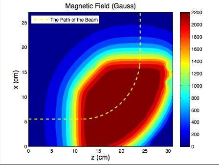
17 RF-GUN developed by LAL RF Gun Normal conducting 2+1/2 cell RF cavity Acceleration under the gradient of 85 MV/m Optimized for high charge, low electrical breakdown and dark current (half cell wall angle, elliptical irises) Optimized for good dynamic vacuum as a necessity for high charge production ( NEG, coating of anti-chamber ) Two coils for the proper focusing of the beam. Gradient (MV/m) z (cm)

18 Laser Laser Developed by RAL


19 Dream Laser DreamLaser Wavelength Pulse length Energy/pulse Train length Rep. rate Beamsize Position


20 Laser setup Harmonics Phase-coding test Phasecoding test Booster amplifie r Cooling 1.5 GHz Synched oscillator Cw preamplifier 10W 3-pass amplifier 3.5kW 2-pass 8.3kW 7.8kW amplifier 14.8mJ in 1.2μs 2ω 3.6kW 4.67mJ in 1.2μs 4ω 1.25kW 1.5mJ in 1.2μs Harmonics test stand Feedback stab. AMP1 head assembly HighQ front end AMP1 and AMP2
21 Laser in IR Laser in UV Electrons Phin parameters DRIVE beam PHIN CLIC charge/bunch (nc) train length (ns) bunch spacing(ns) bunch length (ps) bunch rep rate (GHz) number of bunches machine rep rate (Hz) margine for the laser charge stability <0.25% <0.1% Cathode lifetime (h) at QE > 3% >50 >150 laser wavelegth (nm) energy/micropulse on cathode (nj) energy/micropulse laserroom (nj) energy/macrop. laserroom (uj) 9.8E E+05 mean power (kw) average power at cathode wavelength(w) micro/macropulse stability 1.30% <0.1% conversion efficiency energy/macropulse in IR (mj) energy/micropulse in IR (uj) mean power in IR (kw) average power on second harmonic (W) average power in final amplifier (W) 9 608

22 The maximum achievable charge has been measured as 4.4 nc in this example due to a small laser spot size Charge measurement
23 Charge production Showed in CTF2 already the bunch charge needed (> 10 nc) Total charge test performed in the cathode lab (> 1 mc) 460 h with 1.5% QE have been shown in excellent vacuum Combination of those together has not yet been demonstrated Cathode lifetime under this rough conditions is a big concern Charge production with PHIN
24 Beam loading compensation No Beam RF power in the gun Beam On RF power in the gun Reflected power Reflected power


25 Beam size and Emittance Emittance-meter OTR Profiling
26 Transverse Diagnostics Solenoid scan
27 Multi slit emittance measurment


28 Multi slit emittance, intensity of individual beamlets., mean positions of the beamlets. Emittance Calculation The definition of the transverse geometric emittance., divergences of the beamlets, spread on the divergences.

29 Data analysis


30 Example measurement vs simulation Example: = 10.7 mm mrad for 1.28 nc beam at the energy of 5.5 MeV. The measurement was performed with the laser spot size of 4 mm.
31 Emittance vs charge rf ~ 1.4 mm mrad th < 1 mm mrad It is all about the space charge distribution Can be optimized by laser shaping
32 Time resolved emittance measurements Beam size
33 Time resolved emittance measurements
34 Correlation with rf power


35 Spectrometer Spectrometer

36 Energy and energy spread


37 Time resolved energy spread segmented beam dump
38 QE (%) Cathode lifetime Measurements from 1996 for Cs2Te Lifetime of photocathodes No 36 and QE 37 = 15.3e -t/21 QE 37 = 2.8e -t/476 QE 36 = 6e -t/74 1 QE 36 = 3.2e -t/217 No 36 : Copper plug and : Al = 200 nm; Mg = 370nm ; Te = 10.2 nm ; Cs = 12.2 nm No 37 : Copper plug and : Mo = 200 nm ; Te = 10 nm ; Cs = 13.8 nm RF utilization time (hours) New software enables continuous Qe monitoring

39 Cathode life time studies Correlation with vacuum and bunch charge
40 Cathode life time studies Again strong correlation with the pressure in the gun 9.2 nc! Cathode #185 Cs 2 Te


41 Phase coding 333ps switch 999ps switch
42 Streak measurements after AMP1&2 A.N. Rabiller 999ps switch Using 523nm 2 nd harmonic 333ps switch
43 Streak measurements with Cherenkov-line 333ps switch 999ps switch FCT signal with phase switching A.N. Rabiller

44 Correlation Between the Laser and the electron Beam

45 worst best Stability In laser room In PHIN Macrop IR Green UV Laser RMS Current RMS Train length(ns) RMS stability 0.23% 0.8% 1.3% 1.3% RMS 0.8% RMS 1250 Nonlinear conversion increases noise and causes amplitude variations along the train 2.6% 2.4% 1300 Beam stability seems almost entirely determined by laser stability First tests of feedback system is encouraging We need 0.1% RMS stability
 0.74 (27%) 0.067 (19%) Size y 0.67 2.73 0.")
46 Beam pointing stability June histnlx histnlx 0 Beamposition X stdev=0.079mm sigmasize 0.522mm histnly histnly 0 Beam position Y stdev=0.067mm 0.34mmsigma mm June 2010 no cover Feb 2011 HighQ input & cover Size x Feb 2011 fiber input &cover June 2010 δ movement 0.21 (32%) 0.74 (27%) (19%) Size y δ movement 0.14 (21%) 0.87 (32%) (15.2%)
47 Continuing research program Photo injector option PHIN: study cathode lifetime: lifetime vs bunch charge (2-8 nc), total charge (0.5-4 s pulse length), vacuum activate NEG chamber (partially done) test Cs 3 Sb with green light (next run March 2012) study 8.4 nc beam dynamics, lower gradient? CLIC DB beam: Design 1 GHz rf gun and investigate if full pulse length can be demonstrated
48 CLIC DB injector specifications Parameter Nominal value Unit Beam Energy 50 MeV Pulse Length / s / ns Beam current 4.2 A Bunch charge 8.4 nc Number of bunches Total charge per pulse 590 C Bunch spacing ns Emittance at 50 MeV 100 mm mrad Repetition rate 100 Hz Energy spread at 50 Mev 1 % FWHM Bunch length at 50 MeV 3 mm rms Charge variation shot to shot 0.1 % Charge flatness on flat top 0.1 % Allowed satellite charge < 7 % Allowed switching time 5 ns
49 Challenges for the Photo injector option High single bunch charge 8.4 nc Extremely high total charge per pulse 590 C Cathode life time, dynamic vacuum Extremely high average power for the laser Challenging stability requirements, laser, rf, Challenging 1 GHz rf system, 140 s long pulse RF design and engineering for the rf gun, gradient and cooling Budget situation
50 Conclusions PHIN completely constructed and commissioned Experimental characterizations agrees with simulations Design parameters for CTF3 demonstrated including phase coding and high average charge Pretty good beam and laser stability, needs to be improved for CLIC Working towards a photo injector option for the CLIC DB injector
Diagnostic Systems for Characterizing Electron Sources at the Photo Injector Test Facility at DESY, Zeuthen site
 1 Diagnostic Systems for Characterizing Electron Sources at the Photo Injector Test Facility at DESY, Zeuthen site Sakhorn Rimjaem (on behalf of the PITZ team) Motivation Photo Injector Test Facility at
ICFA ERL Workshop Jefferson Laboratory March 19-23, 2005 Working Group 1 summary Ilan Ben-Zvi & Ivan Bazarov
 ICFA ERL Workshop Jefferson Laboratory March 19-23, 2005 Working Group 1 summary Ilan Ben-Zvi & Ivan Bazarov Sincere thanks to all WG1 participants: Largest group, very active participation. This summary
Introduction. Thermoionic gun vs RF photo gun Magnetic compression vs Velocity bunching. Probe beam design options
 Introduction Following the 19/05/04 meeting at CERN about the "CTF3 accelerated programme", a possible french contribution has been envisaged to the 200 MeV Probe Beam Linac Two machine options were suggested,
The New Superconducting RF Photoinjector a High-Average Current & High-Brightness Gun
 The New Superconducting RF Photoinjector a High-Average Current & High-Brightness Gun Jochen Teichert for the BESSY-DESY-FZD-MBI collaboration and the ELBE crew High-Power Workshop, UCLA, Los Angeles 14
Short Introduction to CLIC and CTF3, Technologies for Future Linear Colliders
 Short Introduction to CLIC and CTF3, Technologies for Future Linear Colliders Explanation of the Basic Principles and Goals Visit to the CTF3 Installation Roger Ruber Collider History p p hadron collider
Photo Injector Test facility at DESY, Zeuthen site
 Photo Injector Test facility at DESY, Zeuthen site PITZ EXPERIENCE ON THE EXPERIMENTAL OPTIMIZATION OF THE RF PHOTO INJECTOR FOR THE EUROPEAN XFEL Mikhail Krasilnikov (DESY) for the PITZ Team FEL 2013
CERN EUROPEAN ORGANIZATION FOR NUCLEAR RESEARCH CTF3 DRIVE BEAM INJECTOR OPTIMISATION
 CERN EUROPEAN ORGANIZATION FOR NUCLEAR RESEARCH CLIC Note 1060 CTF3 DRIVE BEAM INJECTOR OPTIMISATION - 1 Sh. Sanaye Hajari 1, 2, * H. Shaker 1, 2 and S. Doebert 2 Institute for Research in Fundamental
Status of linear collider designs:
 Status of linear collider designs: Electron and positron sources Design overview, principal open issues G. Dugan March 11, 2002 Electron sourcesfor 500 GeV CM machines Parameter TESLA NLC CLIC Cycle rate
VELA/CLARA as Advanced Accelerator Studies Test-bed at Daresbury Lab.
 VELA/CLARA as Advanced Accelerator Studies Test-bed at Daresbury Lab. Yuri Saveliev on behalf of VELA and CLARA teams STFC, ASTeC, Cockcroft Institute Daresbury Lab., UK Outline VELA (Versatile Electron
Accelerator R&D Opportunities: Sources and Linac. Developing expertise. D. Rubin, Cornell University
 Accelerator R&D Opportunities: Sources and Linac D. Rubin, Cornell University Electron and positron sources Requirements Status of R&D Linac Modeling of beam dynamics Development of diagnostic and tuning
Experimental Optimization of Electron Beams for Generating THz CTR and CDR with PITZ
 Experimental Optimization of Electron Beams for Generating THz CTR and CDR with PITZ Introduction Outline Optimization of Electron Beams Calculations of CTR/CDR Pulse Energy Summary & Outlook Prach Boonpornprasert
SLS at the Paul Scherrer Institute (PSI), Villigen, Switzerland
, Villigen, Switzerland") SLS at the Paul Scherrer Institute (PSI), Villigen, Switzerland Michael Böge 1 SLS Team at PSI Michael Böge 2 Layout of the SLS Linac, Transferlines Booster Storage Ring (SR) Beamlines and Insertion Devices
SLS at the Paul Scherrer Institute (PSI), Villigen, Switzerland Michael Böge 1 SLS Team at PSI Michael Böge 2 Layout of the SLS Linac, Transferlines Booster Storage Ring (SR) Beamlines and Insertion Devices
SRF GUN CHARACTERIZATION - PHASE SPACE AND DARK CURRENT MEASUREMENTS AT ELBE*
 SRF GUN CHARACTERIZATION - PHASE SPACE AND DARK CURRENT MEASUREMENTS AT ELBE* E. Panofski #, A. Jankowiak, T. Kamps, Helmholtz-Zentrum Berlin, Berlin, Germany P.N. Lu, J. Teichert, Helmholtz-Zentrum Dresden-Rossendorf,
Experimental Measurements of the ORION Photoinjector Drive Laser Oscillator Subsystem
 Experimental Measurements of the ORION Photoinjector Drive Laser Oscillator Subsystem D.T Palmer and R. Akre Laser Issues for Electron RF Photoinjectors October 23-25, 2002 Stanford Linear Accelerator
LCLS Injector Prototyping at the GTF
 LCLS Injector Prototyping at at the GTF John John Schmerge, SLAC SLAC November 3, 3, 23 23 GTF GTF Description Summary of of Previous Measurements Longitudinal Emittance Transverse Emittance Active LCLS
Investigations on the electron bunch distribution in the longitudinal phase space at a laser driven RF-electron source for the European X-FEL
 Juliane Rönsch Universität Hamburg / DESY Investigations on the electron bunch distribution in the longitudinal phase space at a laser driven RF-electron source for the European X-FEL 5/27/2009 1 Contents
Simulations of the IR/THz Options at PITZ (High-gain FEL and CTR)
") Case Study of IR/THz source for Pump-Probe Experiment at the European XFEL Simulations of the IR/THz Options at PITZ (High-gain FEL and CTR) Introduction Outline Simulations of High-gain FEL (SASE) Simulation
Case Study of IR/THz source for Pump-Probe Experiment at the European XFEL Simulations of the IR/THz Options at PITZ (High-gain FEL and CTR) Introduction Outline Simulations of High-gain FEL (SASE) Simulation
Tomographic transverse phase space measurements at PITZ.
 Tomographic transverse phase space measurements at PITZ. > Photo-Injector Test facility at DESY in Zeuthen - PITZ > Tomography in beam diagnostics > Hardware > Measurements & evaluation Georgios Kourkafas,
Design of an RF Photo-Gun (PHIN)
") Design of an RF Photo-Gun (PHIN) R. Roux 1, G. Bienvenu 1, C. Prevost 1, B. Mercier 1 1) CNRS-IN2P3-LAL, Orsay, France Abstract In this note we show the results of the RF simulations performed with a 2-D
Design of an RF Photo-Gun (PHIN) R. Roux 1, G. Bienvenu 1, C. Prevost 1, B. Mercier 1 1) CNRS-IN2P3-LAL, Orsay, France Abstract In this note we show the results of the RF simulations performed with a 2-D
ASTRA simulations of the slice longitudinal momentum spread along the beamline for PITZ
 ASTRA simulations of the slice longitudinal momentum spread along the beamline for PITZ Orlova Ksenia Lomonosov Moscow State University GSP-, Leninskie Gory, Moscow, 11999, Russian Federation Email: ks13orl@list.ru
Introduction to the benchmark problem
 Introduction to the benchmark problem M. Krasilnikov (DESY) Working group 4: Low emittance electron guns 37th ICFA Beam Dynamics Workshop Future Light Sources 15 19 May 6 DESY, Hamburg, Germany Outline
Dark current at the Euro-XFEL
 Dark current at the Euro-XFEL Jang-Hui Han DESY, MPY Observations at PITZ and FLASH Estimation for the European XFEL Ideas to reduce dark current at the gun DC at FLASH RF gun M1 M2 M3 M4 M5 M6 M7 6 undulator
Development of Soft X-rayX using Laser Compton Scattering
 26 th Advanced ICFA Beam Dynamics Workshop on Nanometre-Size Colliding Beams September 2-6, 2002 at Lausanne Development of Soft X-rayX Source using Laser Compton Scattering R. Kuroda*, S. Kashiwagi*,
Modeling of the secondary electron emission in rf photocathode guns
 Modeling of the secondary electron emission in rf photocathode guns J.-H. Han, DESY Zeuthen 8 June 2004 Joint Uni. Hamburg and DESY Accelerator Physics Seminar Contents 1. Necessity of secondary electron
Dark Current at Injector. Jang-Hui Han 27 November 2006 XFEL Beam Dynamics Meeting
 Dark Current at Injector Jang-Hui Han 27 November 2006 XFEL Beam Dynamics Meeting Considerations for the guns Ultra-low slice emittance of electron beams higher gradient at the gun cavity solenoid field
Low Energy RHIC electron Cooling (LEReC)
") Low Energy RHIC electron Cooling (LEReC) LEReC overview: project goal and cooling approach Alexei Fedotov MEIC Collaboration Meeting 30 31 LEReC Project Mission/Purpose The purpose of the LEReC is to provide
Low Energy RHIC electron Cooling (LEReC) LEReC overview: project goal and cooling approach Alexei Fedotov MEIC Collaboration Meeting 30 31 LEReC Project Mission/Purpose The purpose of the LEReC is to provide
Novel, Hybrid RF Injector as a High-average. Dinh Nguyen. Lloyd Young
 Novel, Hybrid RF Injector as a High-average average-current Electron Source Dinh Nguyen Los Alamos National Laboratory Lloyd Young TechSource Energy Recovery Linac Workshop Thomas Jefferson National Accelerator
Time resolved transverse and longitudinal phase space measurements at the high brightness photo injector PITZ
 Time resolved transverse and longitudinal phase space measurements at the high brightness photo injector PITZ 1. Motivation 2. Transverse deflecting structure 3. Longitudinal phase space tomography 4.
THz Electron Gun Development. Emilio Nanni 3/30/2016
 THz Electron Gun Development Emilio Nanni 3/30/2016 Outline Motivation Experimental Demonstration of THz Acceleration THz Generation Accelerating Structure and Results Moving Forward Parametric THz Amplifiers
SwissFEL INJECTOR DESIGN: AN AUTOMATIC PROCEDURE
 Proceedings of FEL03, New York, NY, USA SwissFEL INJECTOR DESIGN: AN AUTOMATIC PROCEDURE S. Bettoni, M. Pedrozzi, S. Reiche, PSI, Villigen, Switzerland Abstract The first section of FEL injectors driven
Status of Proof-of-Principle Experiment of Coherent Electron Cooling at BNL
 Status of Proof-of-Principle Experiment of Coherent Electron Cooling at BNL Outline 2 Why we doing it? What is Coherent electron Cooling System description Subsystem performance Plan for Run 18 e-n Luminosity
LOLA: Past, present and future operation
 LOLA: Past, present and future operation FLASH Seminar 1/2/29 Christopher Gerth, DESY 8/5/29 FLASH Seminar Christopher Gerth 1 Outline Past Present Future 8/5/29 FLASH Seminar Christopher Gerth 2 Past
1. Beam based alignment Laser alignment Solenoid alignment 2. Dark current 3. Thermal emittance
 Beam based alignment, Dark current and Thermal emittance measurements J-H.Han,M.Krasilnikov,V.Miltchev, PITZ, DESY, Zeuthen 1. Beam based alignment Laser alignment Solenoid alignment 2. Dark current 3.
AWAKE: The Proton Driven Plasma Wakefield Acceleration Experiment at CERN. Alexey Petrenko on behalf of the AWAKE Collaboration
 AWAKE: The Proton Driven Plasma Wakefield Acceleration Experiment at CERN Alexey Petrenko on behalf of the AWAKE Collaboration Outline Motivation AWAKE at CERN AWAKE Experimental Layout: 1 st Phase AWAKE
High Gradient Tests of Dielectric Wakefield Accelerating Structures
 High Gradient Tests of Dielectric Wakefield Accelerating Structures John G. Power, Sergey Antipov, Manoel Conde, Felipe Franchini, Wei Gai, Feng Gao, Chunguang Jing, Richard Konecny, Wanming Liu, Jidong
Juliane Rönsch Hamburg University. Investigations of the longitudinal phase space at a photo injector for the X-FEL
 Juliane Rönsch Hamburg University Investigations of the longitudinal phase space at a photo injector for the X-FEL Juliane Rönsch 1/15/28 1 Contents Introduction PITZ Longitudinal phase space of a photoinjector
Emittance and photocathodes
 Cornell Laboratory for Accelerator-based ScienceS and Education () Emittance and photocathodes Ivan Bazarov Where we are today Injector performance Ongoing work Venues for improvements Next generation
DIAGNOSTIC TEST-BEAM-LINE FOR THE MESA INJECTOR
 DIAGNOSTIC TEST-BEAM-LINE FOR THE MESA INJECTOR I.Alexander,K.Aulenbacher,V.Bechthold,B.Ledroit,C.Matejcek InstitutfürKernphysik,JohannesGutenberg-Universität,D-55099Mainz,Germany Abstract With the test-beam-line
Development of Cs 2 Te photocathode RF gun system for compact THz SASE-FEL
 Development of Cs 2 Te photocathode RF gun system for compact THz SASE-FEL R. Kuroda, H. Ogawa, N. Sei, H. Toyokawa, K. Yagi-Watanabe, M. Yasumoto, M. Koike, K. Yamada, T. Yanagida*, T. Nakajyo*, F. Sakai*
AREAL Test Facility for Advanced Accelerator and Radiation Sources Concepts
 2 nd European Advanced Accelerator Concepts AREAL Test Facility for Advanced Accelerator and Radiation Sources Concepts V. Tsakanov CANDLE SRI 13-19 Sep 2015, La Biodola, Isola d'elba Introduction 2nd
Short Pulse, Low charge Operation of the LCLS. Josef Frisch for the LCLS Commissioning Team
 Short Pulse, Low charge Operation of the LCLS Josef Frisch for the LCLS Commissioning Team 1 Normal LCLS Parameters First Lasing in April 10, 2009 Beam to AMO experiment August 18 2009. Expect first user
Laser acceleration of electrons at Femilab/Nicadd photoinjector
 Laser acceleration of electrons at Femilab/Nicadd photoinjector P. Piot (FermiLab), R. Tikhoplav (University of Rochester) and A.C. Melissinos (University of Rochester) FNPL energy upgrade Laser acceleration
Recent Progress at the CLIC Test Facility 3 at CERN
 Recent Progress at the CLIC Test acility 3 at CERN P. Urschütz Talk outline Introduction to the CLIC two-beam scheme The CLIC Test acility CT3 Results from CT3 Past Recent Results Outlook on future activities
The VELA and CLARA Test Facilities at Daresbury Laboratory Peter McIntosh, STFC on behalf of the VELA and CLARA Development Teams
 The VELA and CLARA Test Facilities at Daresbury Laboratory Peter McIntosh, STFC on behalf of the VELA and CLARA Development Teams Outline VELA & CLARA Accelerators VELA Commissioning VELA Exploitation
Simulations of the IR/THz source at PITZ (SASE FEL and CTR)
") Simulations of the IR/THz source at PITZ (SASE FEL and CTR) Introduction Outline Simulations of SASE FEL Simulations of CTR Summary Issues for Discussion Mini-Workshop on THz Option at PITZ DESY, Zeuthen
Simulations of the IR/THz source at PITZ (SASE FEL and CTR) Introduction Outline Simulations of SASE FEL Simulations of CTR Summary Issues for Discussion Mini-Workshop on THz Option at PITZ DESY, Zeuthen
X-band Experience at FEL
 X-band Experience at FERMI@Elettra FEL Gerardo D Auria Elettra - Sincrotrone Trieste GdA_TIARA Workshop, Ångström Laboratory, June 17-19, 2013 1 Outline The FERMI@Elettra FEL project Machine layout and
CERN EUROPEAN ORGANIZATION FOR NUCLEAR RESEARCH THE CLIC POSITRON CAPTURE AND ACCELERATION IN THE INJECTOR LINAC
 CERN EUROPEAN ORGANIZATION FOR NUCLEAR RESEARCH CLIC Note - 819 THE CLIC POSITRON CAPTURE AND ACCELERATION IN THE INJECTOR LINAC A. Vivoli 1, I. Chaikovska 2, R. Chehab 3, O. Dadoun 2, P. Lepercq 2, F.
THERMAL EMITTANCE MEASUREMENTS AT THE SwissFEL INJECTOR TEST FACILITY
 THERMAL EMITTANCE MEASUREMENTS AT THE SwissFEL INJECTOR TEST FACILITY E. Prat, S. Bettoni, H. H. Braun, M. C. Divall, R. Ganter, T. Schietinger, A. Trisorio, C. Vicario PSI, Villigen, Switzerland C. P.
BERLinPro. An ERL Demonstration facility at the HELMHOLTZ ZENTRUM BERLIN
 BERLinPro An ERL Demonstration facility at the HELMHOLTZ ZENTRUM BERLIN BERLinPro: ERL demonstration facility to prepare the ground for a few GeV ERL @ Berlin-Adlershof Goal: 100MeV, 100mA beam Small emittance,
Commissioning of the new Injector Laser System for the Short Pulse Project at FLASH
 Commissioning of the new Injector Laser System for the Short Pulse Project at FLASH Uni Hamburg tim.plath@desy.de 05.11.2013 Supported by BMBF under contract 05K10GU2 & FS FLASH 301 Motivation short pulses
The CeB6 Electron Gun for the Soft-X-ray FEL Project at SPring-8
 May 25, 2004 DESY, Hamburg, Germany The CeB6 Electron Gun for the Soft-X-ray FEL Project at SPring-8 K. Togawa SPring-8 / RIKEN Harima Institute T. Shintake, H. Baba, T. Inagaki, T. Tanaka SPring-8 / RIKEN
Low slice emittance preservation during bunch compression
 Low slice emittance preservation during bunch compression S. Bettoni M. Aiba, B. Beutner, M. Pedrozzi, E. Prat, S. Reiche, T. Schietinger Outline. Introduction. Experimental studies a. Measurement procedure
Free-electron laser SACLA and its basic. Yuji Otake, on behalf of the members of XFEL R&D division RIKEN SPring-8 Center
 Free-electron laser SACLA and its basic Yuji Otake, on behalf of the members of XFEL R&D division RIKEN SPring-8 Center Light and Its Wavelength, Sizes of Material Virus Mosquito Protein Bacteria Atom
THE LCLS-II INJECTOR DESIGN*
 THE LCLS-II INJECTOR DESIGN* J.F. Schmerge #, A. Brachmann, D. Dowell, A. Fry, R.K. Li, Z. Li, T. Raubenheimer, T. Vecchione, F. Zhou, SLAC, Menlo Park, CA 94025, USA A. Bartnik, I. Bazarov, B. Dunham,
Motivation of emission studies at PITZ
 Motivation of emission studies at PITZ PITZ activities to understand the discrepancies between measurements and simulations in: Transverse phase space Optimum machine parameters Auxiliary measurements
Accelerator Activities at PITZ
 Accelerator Activities at PITZ Plasma acceleration etc. Outline > Motivation / Accelerator Research & Development (ARD) > Plasma acceleration Basic Principles Activities SINBAD > ps-fs electron and photon
Injector Experimental Progress
 Injector Experimental Progress LCLS TAC Meeting December 10-11 2001 John Schmerge for the GTF Team GTF Group John Schmerge Paul Bolton Steve Gierman Cecile Limborg Brendan Murphy Dave Dowell Leader Laser
Alignment requirement for the SRF cavities of the LCLS-II injector LCLSII-TN /16/2014
 Alignment requirement for the SRF cavities of the LCLS-II injector LCLS-II TN-14-16 12/16/2014 R. K. Li, C. Papadopoulos, T. O. Raubenheimer, J. F. Schmerge, and F. Zhou December 16, 2014 LCLSII-TN-14-16
Positron Source using Channelling for the Baseline of the CLIC study
 CLIC = Compact Linear Collider Positron Source using Channelling for the Baseline of the CLIC study Louis Rinolfi With contributions from: X. Artru 2, R. Chehab 2, O. Dadoun 3, E. Eroglu 4, K. Furukawa
New Electron Source for Energy Recovery Linacs
 New Electron Source for Energy Recovery Linacs Ivan Bazarov 20m Cornell s photoinjector: world s brightest electron source 1 Outline Uses of high brightness electron beams Physics of brightness High brightness
Beam dynamics studies for PITZ using a 3D full-wave Lienard-Wiechert PP code
 Beam dynamics studies for PITZ using a 3D full-wave Lienard-Wiechert PP code Y. Chen, E. Gjonaj, H. De Gersem, T. Weiland TEMF, Technische Universität Darmstadt, Germany DESY-TEMF Collaboration Meeting
Particle Driven Acceleration Experiments
 Particle Driven Acceleration Experiments Edda Gschwendtner CAS, Plasma Wake Acceleration 2014 2 Outline Introduction Motivation for Beam Driven Plasmas Wakefield Acceleration Experiments Electron and proton
PAL LINAC UPGRADE FOR A 1-3 Å XFEL
 PAL LINAC UPGRADE FOR A 1-3 Å XFEL J. S. Oh, W. Namkung, Pohang Accelerator Laboratory, POSTECH, Pohang 790-784, Korea Y. Kim, Deutsches Elektronen-Synchrotron DESY, D-603 Hamburg, Germany Abstract With
WG2 on ERL light sources CHESS & LEPP
 Charge: WG2 on ERL light sources Address and try to answer a list of critical questions for ERL light sources. Session leaders can approach each question by means of (a) (Very) short presentations (b)
4GLS Status. Susan L Smith ASTeC Daresbury Laboratory
 4GLS Status Susan L Smith ASTeC Daresbury Laboratory Contents ERLP Introduction Status (Kit on site ) Plan 4GLS (Conceptual Design) Concept Beam transport Injectors SC RF FELs Combining Sources May 2006
Pushing the limits of laser synchrotron light sources
 Pushing the limits of laser synchrotron light sources Igor Pogorelsky National Synchrotron Light Source 2 Synchrotron light source With λ w ~ several centimeters, attaining XUV region requires electron
Multivariate Optimization of High Brightness High Current DC Photoinjector. Ivan Bazarov
 Multivariate Optimization of High Brightness High Current DC Photoinjector Ivan Bazarov Talk Outline: Motivation Evolutionary Algorithms Optimization Results 1 ERL Injector 750 kv DC Gun Goal: provide
Microbunching Workshop 2010 March 24, 2010, Frascati, Italy. Zhirong Huang
 Measurements of the LCLS Laser Heater and its impact on the LCLS FEL Performance Z. Huang for the LCLS commissioning team LCLS 1 1 Outline Introduction LCLS setup and measurements Effects on FEL performance
COMBINER RING LATTICE
 CTFF3 TECHNICAL NOTE INFN - LNF, Accelerator Division Frascati, April 4, 21 Note: CTFF3-2 COMBINER RING LATTICE C. Biscari 1. Introduction The 3 rd CLIC test facility, CTF3, is foreseen to check the feasibility
Development of reliable and sophisticated photo injector system and future plan
 Development of reliable and sophisticated photo injector system and future plan Hiromitsu Tomizawa Accelerator Division, Japan Synchrotron Radiation Research Institute (JASRI/SPring-8) Kouto, Sayo-cho,
A Polarized Electron PWT Photoinjector for the ILC
 2005 ALCPG & ILC Workshops Snowmass, U.S.A. A Polarized Electron PWT Photoinjector for the ILC David Yu, Yan Luo, Alexei Smirnov, DULY Research Inc., Rancho Palos Verdes, CA 90275 Ivan Bazarov, Cornell
FACET-II Design Update
 FACET-II Design Update October 17-19, 2016, SLAC National Accelerator Laboratory Glen White FACET-II CD-2/3A Director s Review, August 9, 2016 Planning for FACET-II as a Community Resource FACET-II Photo
Magnetized Beam LDRD. Abdullah Mamun On behalf of JLab Injector Group. JLEIC Collaboration Meeting Spring 2018, March 26-28,, Jefferson Lab
 Magnetized Beam LDRD Abdullah Mamun On behalf of JLab Injector Group JLEIC Collaboration Meeting Spring 2018, March 26-28,, Jefferson Lab Outline Magnetized Bunched-Beam Electron Cooling LDRD Magnetized
Emittance and Quantum Efficiency Measurements from a 1.6 cell S- Band Photocathode RF Gun with Mg Cathode *
 LCLS-TN-4-3 SLAC PUB 763 September, 4 Emittance and Quantum Efficiency Measurements from a.6 cell S- Band Photocathode RF Gun with Mg Cathode * J.F. Schmerge, J.M. Castro, J.E. Clendenin, D.H. Dowell,
Photo Injector Test facility at DESY, Zeuthen site. PITZ: facility overview
 Photo Injector Test facility at DESY, Zeuthen site. PITZ: facility overview Mikhail Krasilnikov (DESY) for the PITZ Team Mini-workshop on THz option at PITZ, Zeuthen, 22.09.2015 Photo Injector Test facility
Jlab FEL Photoemission DC Guns
 Jlab FEL Photoemission DC Guns Fay Hannon On behalf of the FEL team FLS 2010, 2 nd March 2 Operational Guns 1. FEL Gun 60m Gun Test Stand (GTS) 2. Backup gun, test stand with beam characterization beamline
Photoinjector design for the LCLS
 SLAC-PUB-8962 LCLS-TN-01-05 Revised November 2001 Photoinjector design for the LCLS P.R. Bolton a, J.E. Clendenin a, D.H. Dowell a, M. Ferrario b, A.S. Fisher a, S.M. Gierman a, R.E. Kirby a, P. Krejcik
Generation and characterization of ultra-short electron and x-ray x pulses
 Generation and characterization of ultra-short electron and x-ray x pulses Zhirong Huang (SLAC) Compact XFEL workshop July 19-20, 2010, Shanghai, China Ultra-bright Promise of XFELs Ultra-fast LCLS Methods
The MAX IV Thermionic preinjector
 The MAX IV Thermionic preinjector David Olsson ESLS RF, Lund, 2015-09-30 Injection Requirements I Full-energy injection from the LINAC 1.5 GeV and 3 GeV extraction points. Both storage rings will be operated
Magnetized Beam Update (LDRD)
") Magnetized Beam Update (LDRD) JLEIC Collaboration Meeting March 29, 2016 Riad Suleiman and Matt Poelker Outline Magnetized Bunched Electron Beam Requirements Magnetized Sources JLEIC Magnetized Beam LDRD
Magnetized Beam Update (LDRD) JLEIC Collaboration Meeting March 29, 2016 Riad Suleiman and Matt Poelker Outline Magnetized Bunched Electron Beam Requirements Magnetized Sources JLEIC Magnetized Beam LDRD
ERL FACILITY AT CERN FOR APPLICATIONS
 ERL FACILITY AT CERN FOR APPLICATIONS Erk Jensen (CERN) Big thanks to contributors: A. Bogacz (JLAB), O. Brüning, R. Calaga, V. Chetvertkova, E. Cormier (CELIA), R. Jones, M. Klein, A. Valloni, D. Pellegrini,
Diagnostics at the MAX IV 3 GeV storage ring during commissioning. PPT-mall 2. Åke Andersson On behalf of the MAX IV team
 Diagnostics at the MAX IV 3 GeV storage ring during commissioning PPT-mall 2 Åke Andersson On behalf of the MAX IV team IBIC Med 2016, linje Barcelona Outline MAX IV facility overview Linac injector mode
LCLS Accelerator Parameters and Tolerances for Low Charge Operations
 LCLS-TN-99-3 May 3, 1999 LCLS Accelerator Parameters and Tolerances for Low Charge Operations P. Emma SLAC 1 Introduction An option to control the X-ray FEL output power of the LCLS [1] by reducing the
Progress towards slice emittance measurements at PITZ. Raffael Niemczyk for the PITZ team, Würzburg, March 20 th 2018
 Progress towards slice emittance measurements at PITZ Raffael Niemczyk for the PITZ team, Würzburg, March 20 th 2018 PITZ Overview Photo-Injector Test Facility at DESY, Zeuthen Site > Three Emittance Measurement
Multivariate Optimization of High Brightness High Current DC Photoinjector. Ivan Bazarov Cornell University
 Multivariate Optimization of High Brightness High Current DC Photoinjector Ivan Bazarov Cornell University Talk Outline: Motivation Parallel Evolutionary Algorithms Results & Outlook Ivan Bazarov, Multivariate
Optimum beam creation in photoinjectors using spacecharge expansion II: experiment
 Optimum beam creation in photoinjectors using spacecharge expansion II: experiment J. Rosenzweig, A. Cook, M. Dunning, R.J. England, G. Travish, UCLA P. Musumeci, C. Vicario, D. Filippetto, M. Ferrario,
Cornell Injector Performance
 Cornell Injector Performance Adam Bartnik 1 Cornell Injector Performance as an ERL injector 2 Cornell Injector Performance as an ERL injector as an FEL injector (e.g. LCLS-II) as an injector for EIC applications
Field Emission and Channeling Radiation for High-Spectral-Brilliance X-ray Sources
 Field Emission and Channeling Radiation for High-Spectral-Brilliance X-ray Sources Charles Brau, Bo Choi, William Gabella, Anthony Hmelo, John Kozub, Borislav Ivanov, Jonathan Jarvis, Marcus Mendenhall
THE COMPACT LINEAR COLLIDER (CLIC) STUDY
 STUDY") THE COMPACT LINEAR COLLIDER (CLIC) STUDY J.P.Delahaye for The Compact LInear Collider Study Team The CLIC study is a site independent feasibility study aiming at the development of a realistic technology
THE COMPACT LINEAR COLLIDER (CLIC) STUDY J.P.Delahaye for The Compact LInear Collider Study Team The CLIC study is a site independent feasibility study aiming at the development of a realistic technology
CLIC THE COMPACT LINEAR COLLIDER
 CLIC THE COMPACT LINEAR COLLIDER Emmanuel Tsesmelis Directorate Office, CERN 9 th Corfu Summer Institute 4 September 2009 1 THE CLIC ACCELERATOR 2 Linear Collider Baseline LEP: 209 GeV next Electron-Positron
ThomX Machine Advisory Committee. (LAL Orsay, March ) Ring Beam Dynamics
 Ring Beam Dynamics") ThomX Machine Advisory Committee (LAL Orsay, March 20-21 2017) Ring Beam Dynamics A. Loulergue, M. Biagini, C. Bruni, I. Chaikovska I. Debrot, N. Delerue, A. Gamelin, H. Guler, J. Zang Programme Investissements
ThomX Machine Advisory Committee (LAL Orsay, March 20-21 2017) Ring Beam Dynamics A. Loulergue, M. Biagini, C. Bruni, I. Chaikovska I. Debrot, N. Delerue, A. Gamelin, H. Guler, J. Zang Programme Investissements
THE CLIC PROJECT - STATUS AND PROSPECTS
 THE CLIC PROJECT - STATUS AND PROSPECTS E. Adli, University of Oslo, Norway On behalf of the CLIC/CTF3 collaboration Abstract Following the feasibility demonstration of the novel CLIC technology and the
SCSS Prototype Accelerator -- Its outline and achieved beam performance --
 SCSS Prototype Accelerator -- Its outline and achieved beam performance -- Hitoshi TANAKA RIKEN, XFEL Project Office 1 Content 1. Light Quality; SPring-8 v.s. XFEL 2. What are the critical issues? 3. Mission
Tomography module for transverse phase-space measurements at PITZ.
 Tomography module for transverse phase-space measurements at PITZ. > Photo-Injector Test facility @ DESY in Zeuthen - PITZ > Tomography module > Measurement results > Conclusions and outlook G. Asova for
DESIGN AND CONSTRUCTION OF LOW ENERGY ELECTRON ACCELERATORS AT SINP MSU
 DESIGN AND CONSTRUCTION OF LOW ENERGY ELECTRON ACCELERATORS AT SINP MSU V. Shvedunov Skobeltsyn Institute of Nuclear Physics Lomonosov Moscow State University 26 November 2013 Betatron 1959-1985 Low intensity
ASTRA BASED SWARM OPTIMIZATIONS OF THE BERLinPro INJECTOR
 ASTRA BASED SWARM OPTIMIZATIONS OF THE BERLinPro INJECTOR M. Abo-Bakr FRAAC4 Michael Abo-Bakr 2012 ICAP Warnemünde 1 Content: Introduction ERL s Introduction BERLinPro Motivation Computational Aspects
The design for the LCLS rf photo-injector
 SLAC-PUB-8054 January 1999 The design for the LCLS rf photo-injector R. Alley, V. Bharadwaj, J. Clendenin, P. Emma, A. Fisher, J. Frisch, T. Kotseroglou, R. Miller, D. T. Palmer, J. Schmerge, J. C. Sheppard,
Simulation of the Beam Dump for a High Intensity Electron gun
 EUROPEAN ORGANIZATION FOR NUCLEAR RESEARCH CERN BEAMS DEPARTMENT CERN-BE-2014-007 BI Simulation of the Beam Dump for a High Intensity Electron gun S. Doebert; T. Lefèvre; A, Jeff; CERN Geneva/CH K. Pepitone
TTF and VUV-FEL Injector Commissioning
 TESLA Collaboration Meeting Sep. 6-8, 2004 Orsay TTF and VUV-FEL Injector Commissioning Siegfried Schreiber, Klaus Floettmann DESY Brief description of the injector Basic measurements Preliminary results
High gradient, high average power structure development at UCLA and Univ. Rome in X-X. band
 High gradient, high average power structure development at UCLA and Univ. Rome in X-X and S-S band May 23-25, 25, 2007 US High Gradient Research Collaboration Workshop Atsushi Fukasawa, James Rosenzweig,