Investigations on the electron bunch distribution in the longitudinal phase space at a laser driven RF-electron source for the European X-FEL
|
|
|
- Sharon Burke
- 5 years ago
- Views:
Transcription
1 Juliane Rönsch Universität Hamburg / DESY Investigations on the electron bunch distribution in the longitudinal phase space at a laser driven RF-electron source for the European X-FEL 5/27/2009 1
2 Contents Introduction & Motivation PITZ (Photoinjector Test facility DESY, Zeuthen site) Example for the longitudinal phase space distribution Devices for longitudinal phase space measurement at PITZ Measurements and simulations of longitudinal phase space at PITZ Summary 2
3 Introduction Free Electron Laser produces light with the following properties: short wavelength (XFEL: down to 0.1 nm, FLASH: down to 6 nm) -> small structures coherent -> holography, imaging of single nanoscale objects short pulses ( 100 fs) -> fast processes high peak brightness -> investigate matter under extreme conditions 3
4 Introduction To obtain a highly brilliant light pulse a high energy electron beam with the following properties is required: a high peak current, means a high charge within a short bunch length (in the range of 100 fs) a small energy spread a small transverse emittance FLASH layout 4
 a small energy spread a small transverse emittance FLASH layout production of bunches with high charge (1nC), medium bunch duration")

5 Motivation To obtain a highly brilliant light pulse a high energy electron beam with the following properties is required: a high peak current, means a high charge within a short bunch length (in the range of 100 fs) a small energy spread a small transverse emittance FLASH layout production of bunches with high charge (1nC), medium bunch duration (20ps), small energy spread and small transverse emittance acceleration of electron bunches and conservation of transverse emittance compression of the bunches to reach a high peak current compression: requires the knowledge of long. phase space distribution generation of brilliant light pulse by the SASE (Self amplified spontanious emission) process 5

6 PITZ: Photoinjector test facility at DESY, Zeuthen site Goals: Test, analyse and optimize electron sources for FELs Development of diagnostics to analyse the electron bunch properties Comparison of measurements and simulations to prove the understanding of the beam dynamics in the photoinjector 6
7 PITZ : RF gun RFgun: L band (1.3 GHz) normal conducting standing wave 1.6 cell cavity Coaxial RF coupler 7
8 PITZ : RF gun RFgun: L band (1.3 GHz) normal conducting standing wave 1.6 cell cavity Cathode laser 257 / 262nm ~20ps (FWHM) Photo cathode (Cs2Te) QE~0.5 5% Vacuum mirror UHV Coaxial RF coupler Electron bunch 1nC, ~5 7MeV 7
9 PITZ : RF gun RFgun: L band (1.3 GHz) normal conducting standing wave 1.6 cell cavity Bucking solenoid Main solenoid, Bz_peak~0.2T Cathode laser 257 / 262nm ~20ps (FWHM) Photo cathode (Cs2Te) QE~0.5 5% Vacuum mirror UHV Coaxial RF coupler Electron bunch 1nC, ~5 7MeV 7
10 PITZ: RF gun launch phase E(t) Φ: launch phase ωt 8

11 PITZ: photocathode laser 8
12 PITZ: electron beam line GUN cavity BOOSTER cavity 10
13 PITZ diagnostics of electron beam properties bunch charge: faraday cups Integrating current transformers (ICTs) GUN cavity BOOSTER cavity beam position & size: view screens and CCD cameras wire scanners BPMs transverse phase space distribution and emittance: slit mask stations (slit scan method) tomography module slice emittance: RF deflector and tomography module dipole, slit, quadrupole quadrupole, silica aerogel and streak camera 10
14 Contribution to PITZ diagnostics diagnostics of longitudinal bunch properties HEDA1: High Energy Dispersive Arm 1 LEDA: Low Energy Dispersive Arm BOOSTER cavity GUN cavity modified in order to adjust to higher beam energies first measurements performed designed commissioned first measurements performed longitudinal phase space distribution: momentum distribution temporal distribution longitudinal phase space distribution HEDA2: High Energy Dispersive Arm 2 first design considerations 11
15 Simulated longitudinal phase space distribution 1 nc 60 MV/m 0.5 m after the cathode phase of max. momentum gain Bmain = 176 mt cathode laser: long.: flat top FWHM : 20 ps rise time : 2 ps transv.: flat top Ø : 2 mm pz (MeV/c) head tail pz (MeV/c) projections of longitudinal phase space distribution: longitudinal momentum distribution temporal distribution area of longitudinal phase space: longitudinal emittance εz εz = <(Δpz)2> <(Δz)2> <Δpz Δz>2 12

16 pz (MeV/c) Simulated longitudinal phase space distribution pmean = 6.87 MeV/c prms = 23.1 kev/c pz (MeV/c) 1 nc 60 MV/m 0.5 m after the cathode phase of max. momentum gain Bmain = 176 mt cathode laser: long.: flat top FWHM : 20 ps rise time : 2 ps transv.: flat top Ø : 2 mm 13
17 Simulated longitudinal phase space distribution pz (MeV/c) pmean = 6.87 MeV/c prms = 5.95 kev/c head tail pz (MeV/c) 0.1 nc 60 MV/m 0.5 m after the cathode phase of max. momentum gain Bmain = 176 mt cathode laser: long.: flat top FWHM : 20 ps rise time : 2 ps transv.: flat top Ø : 2 mm Reduction of the charge for 1 nc to 100 pc causes a reduction of space charge forces and thus momentum spread, slice momentum spread (<1 kev/c along the whole bunch) and bunch length 14
18 Devices for measurements of longitudinal phase space distributions at PITZ Temporal charge distribution: Silica aerogel (Cherenkov radiator) or OTR (optical transition radiator) as radiators and a streak camera RF deflector Beam momentum distribution: dipole magnet and a view screen Longitudinal phase space distribution: dipole magnet, radiator and streak camera RF deflector and dipole magnet 15
19 pz (MeV/c) Devices for measurements of plongitudinal = 6.87 MeV/c p = 23.1 kev/c phase space distributions at PITZ mean rms Temporal charge distribution: Silica aerogel (Cherenkov radiator) or OTR (optical transition radiator) as radiators and a streak camera pz (MeV/c) Simulated temporal charge density distribution (1 nc) 16

20 Devices for measurements of longitudinal distributions at PITZ Temporal charge distribution: Silica aerogel or OTR as radiators and a streak camera electron bunch produces a light pulse with similar temporal distribution by the Cherenkov effect or transition radiation light transport streak camera measurement Silica aerogel n = Cherenkov radiator 17


21 Devices for measurements of longitudinal distributions at PITZ number of photons emission angle difficult to image without light losses The number of photons produced by silica aerogel (up to 40 MV/m) is several orders of magnitude higher than the number of photons produced by an OTR screen. 18
22 Optical transmission line LEDA The optical system is contains telescopes consisting of achromatic lenses. HEDA1 LOW.Scr3 2 full cone 1 partial cone 2 full cone (old) HIGH1.Scr2 measured arrival time at the streak camera The optical system limits the temporal resolution due to dispersion. The temporal resolution can be reduced by using narrow bandwidth wavelength filter, but at the expense of the reduced number of photons. A system consisting of reflective optics is under development. 19
23 Influence of the streak camera (C5680) resolution is limited by: streak camera slit width and space charge slit width of 100 µm: Δt = 1.75 ps correction: deconvolution (signal without RF field) RF jitter and jitter of signal arrival time (due to the overlap of several measurements) diff. momentum of photo electrons for diff. wavelength from Hamamatsu home page, C5680 series ( comp.com) 20
![Temporal resolution Limitation of the temporal resolution by the different Cherenkov radiators p [MeV/c] n : index of refraction d : thickness Limitation of the temporal resolution by the optical](/docs-images/95/125565890/images/24-1.jpg "system using an optical transmission filter of 550 nm with 10 nm bandwidth and a streak camera slit width of 0.1 mm temporal resolution by the optical system and the streak camera (0.")
24 Temporal resolution Limitation of the temporal resolution by the different Cherenkov radiators p [MeV/c] n : index of refraction d : thickness Limitation of the temporal resolution by the optical system using an optical transmission filter of 550 nm with 10 nm bandwidth and a streak camera slit width of 0.1 mm temporal resolution by the optical system and the streak camera (0.1 mm slit width) is about 4 ps FWHM 21
25 Devices for the measurement of the longitudinal phase space distribution at PITZ Beam momentum distribution: dipole magnet and a view screen simulated longitudinal momentum distribution (1 nc) 22
26 Devices for the measurement of the momentum distribution at PITZ p = e / Bdipole (l) dl pc = e Bdipole leff / Δp = pc Δy / R16 yda y'da xda x'da tda ΔpDA/pDA p1 < p2 p1 p2 spatial distribution of the momenta in the bunch CCD camera YAG screen = R11 R12 R21 R R51 R R33 R34 R43 R R16 R R56 1 y0 y'0 x0 x'0 t0 Δp0/p0 vertical position of a particle: y = R11 y0 + R12 y'0 + R16 Δp0 /p0 R16 Δp0 /p0 R11 y0 + R12 y'0 23
27 Devices for the measurement of the longitudinal phase space distribution at PITZ Longitudinal phase space distribution: dipole magnet, radiator and streak camera simulated longitudinal phase space distribution (1 nc) 13 24
28 Devices for the measurement of the longitudinal phase space distribution at PITZ y = R11 y0 + R12 y'0 + R16 Δp0 /p0 t = R51 y0 + R52 y'0 + t0 + R56 Δp0 /p0 R16 Δp0 /p0 R11 y0 + R12 y'0 correction by shearing the image correction by deconvolution electron bunch spatial distribution of the momenta in the bunch CCD camera light distribution equivalent to temporal and spatial distribution of the electron bunch behind the dipole (produced by a radiator) YAG screen/ radiator light pulse equivalent to temporal distribution of the electron bunch (produced by a radiator) radiator with optical transmission line transported to streak camera 25
29 Example for a spectrometer magnet (first high energy dispersive arm - HEDA1) L1 L2 Booster Q2 180 dipole magnet S2 D Gun L2 S1 Q1 Dump 1 M S= 0 0 L 1 +L Slit 1 L 1 L 2 2ρ M D= vertical distribution y = R11 y0 + R12 y'0 + R16 Δp0 /p0 R16 Δp0 /p0 R11 y0 + R12 y'0 26
 L1 L2 Booster Q2 S2 D 180 dipole")

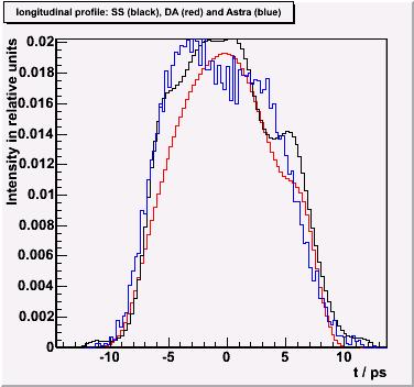
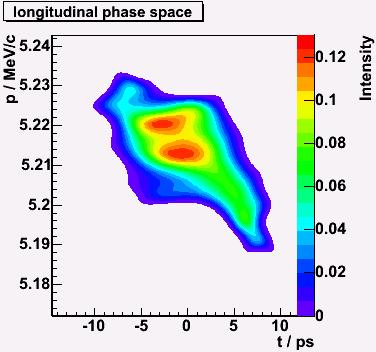
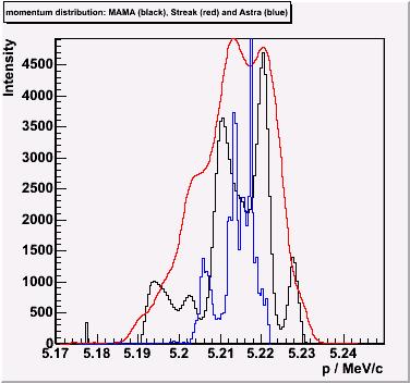
30 Example for a spectrometer magnet (first high energy dispersive arm - HEDA1) L1 L2 Booster Q2 S2 D 180 dipole magnet Gun L2 S1 Q1 Dump Measurement Slit ASTRA Simulation Simulation convoluted with resolution of streak beam line 27
31 The longitudinal phase space distribution is affected by: Space charge RF field distribution of gun and booster cavity (field strength, initial phase) Laser properties (duration of the laser pulse) transverse and longitudinal charge distribution/density Emission effects Mirror charge Schottky like effect (emission enhancement due to electric field at the cathode ) These properties and effects are coupled. 28
32 Measurements of longitudinal phase space distribution Dependence on bunch charge: pz & prms for different gun phases after the gun z after the gun longitudinal phase space distribution after the gun Dependence on increased beam energy pz vs. gun gradient pz vs. booster gradient pz & z vs. gun and booster phase Dependence on laser properties z vs. xy laser long. phase space distribution for diff. temp. laser distribution 29


33 Momentum measurement (influence of gun phase and bunch charge) simulation 1 nc 30 pc measurement simulation 1 nc 30 pc measurement Gun gradient: ~40MV/m The dependence of the mean momentum on the launch phase is similar for different charge highest mean momentum: 4.8 MeV/c at launch phase: of about 37 minimum momentum spread: 30 pc: 5 kev/c at launch phase: of about 35 1 nc: 13 kev/c at launch phase: of about 30 for phase from 80 to 100 the momentum distribution is cut by the screen 1nC: space charge increases momentum spread 30 pc: phase of max. momentum gain is close to phase of min. momentum spread space charge forces small 30
34 Bunch length measurement (influence of charge) 40 MV/m phase of max. momentum gain laser: long.: flat top FWHM : 20 ps risetime : 7 ps transv.: flat top Ø : 2 mm 31

35 Simulations of the longitudinal phase space at different long. positions and charges 38 pc Astra measured 1 nc - 45 MV/m, - flat-top temporal and transverse laser distribution, - phase of max. momentum gain modulation in the initial laser distribution cause modulations in the longitudinal phase space distribution small charges: strong modulations appear in the longitinal phase space distribution 32


36 Measurements of the longitudinal phase space distribution at different charges Measurement ASTRASimulation Momentum distribution Temporal bunch distribution 30 pc 0.2 nc 1 nc ASTRA streak YAG ASTRA disp. arm temp. distr. 33
37 Momentum measurement (influence of gun gradient) pmax (MeV/c) ASTRA Simulation max. <p> without SCF max. <p> with SCF min prms with SCF difference SCF (space charge forces are reduced faster max. mean momentum scales linear with the gradient (for Ecath > 20 MV/m) for E < 18 MV/m: phase of max. mean momentum gain = 0 for E < 6 MV/m: no acceleration 34

38 Momentum measurement (influence of booster gradient) TESLA booster (9 cell copper cavity) field distribution is only roughly known the average power is limited by the cavity cooling The points display measurementon different days during an measurement periode for: - gun and booster phase of max. momentum gain 35


39 Momentum measurement (influence of gun & booster phase) 1 nc gun gradient: 40 MV/m gun phase of max. momentum gain (top) booster gradient: 12.5 MV/m Laser: long.: flat top FWHM : 20 ps rise : 7 ps transv.: flat top Ø : 2 mm 36

40 Bunch length downstream the booster cavity simulations Bunch duration vs. the booster phase pzmean = 15.9 MeV/c Parameter: 800 pc transv. laser diameter = 1.5mm Flat-top laser strong off-crest operation: balistic bunching low beam energy space charge transverse emittance growth 37
41 Bunch length measurements 1 nc 60 MV/m laser: long.: gaussian FWHM : 2 ps transv.: flat top Ø : variable space charge dominated beam coupling of the transverse beam size and the longitudinal bunch properties 38
42 Influence of laser temporal modulations on longitudinal phase space distribution (simulations for old cathode laser system) Different initial laser distributions momentum distributions Resulting different charge distributions longitudinal phase space distributions 1 nc z=8m gun gradient: 60 MV/m gun & booster phase of max. momentum gain booster gradient (CDS): MV/m Laser: transv.: flat top Ø : 2 mm The modulations in the temporal laser distribution introduce modulations in the longitudinal phase space and momentum distribution. 39
 simulated (flat top) measured simulated (10")

43 Influence of laser temporal modulations on longitudinal phase space distribution (new cathode laser system) Different initial laser distributions Resulting different momentum distributions measured simulated (10 gauss) simulated (flat top) measured simulated (10 gauss) simulated (flat top) FWHM = 20 ps rise time = 2 ps modulations in the temporal laser distribution translate into modulations in themomentum distribution 500 pc gun gradient: 60 MV/m gun phase of max. momentum gain 10 Laser: transv.: flat top Ø : 1.5 mm 40
44 Summary A method to measure the longitudinal phase space distribution and its projection used at PITZ was presented. The limit of the resolution of this method was analysed: the major limitation of the temporal resolution is the optical system. an optical system of reflective optics is under development. The spectrometer dipole magnets were optimized for high momentum resolution. The influence of space charge force on the longitudinal phase space distribution was studied in dependence on the bunch charge The impact of the increased gun gradient onto the longitudinal phase space distribution has been investigated. Bunch length dependence by off-crest booster operation was studied. A transformation of longitudinal modulations of the laser into momentum modulations has been experimentally observed and can be generally reproduced by simulations. Space charge density increase causes strong coupling between transverse and longitudinal bunch properties. 41
45 Thanks to: You, for your attention J. Roßbach, B. Schmidt, S. Schreiber, C. Hagner J. Bähr, F. Stephan, D. Lipka, M. Krasilnikov, C. Boulware, S. Khodyachykh, S. Rimjaem, K. Rosbach and all the colleagues at PITZ K. Flöttmann D. Dowell, C. Limbourg and P. Emma T. Kamps 42
Juliane Rönsch Hamburg University. Investigations of the longitudinal phase space at a photo injector for the X-FEL
 Juliane Rönsch Hamburg University Investigations of the longitudinal phase space at a photo injector for the X-FEL Juliane Rönsch 1/15/28 1 Contents Introduction PITZ Longitudinal phase space of a photoinjector
RF-Gun Experience at PITZ - Longitudinal Phase Space
 - Collaboration meeting 9th of October 2006 Hamburg University Juliane Rönsch 1 Motivation special device to measure the longitudinal phase space at low momentum typical high energy diagnostics can not
Diagnostic Systems for Characterizing Electron Sources at the Photo Injector Test Facility at DESY, Zeuthen site
 1 Diagnostic Systems for Characterizing Electron Sources at the Photo Injector Test Facility at DESY, Zeuthen site Sakhorn Rimjaem (on behalf of the PITZ team) Motivation Photo Injector Test Facility at
Time resolved transverse and longitudinal phase space measurements at the high brightness photo injector PITZ
 Time resolved transverse and longitudinal phase space measurements at the high brightness photo injector PITZ 1. Motivation 2. Transverse deflecting structure 3. Longitudinal phase space tomography 4.
Introduction to the benchmark problem
 Introduction to the benchmark problem M. Krasilnikov (DESY) Working group 4: Low emittance electron guns 37th ICFA Beam Dynamics Workshop Future Light Sources 15 19 May 6 DESY, Hamburg, Germany Outline
Experimental Optimization of Electron Beams for Generating THz CTR and CDR with PITZ
 Experimental Optimization of Electron Beams for Generating THz CTR and CDR with PITZ Introduction Outline Optimization of Electron Beams Calculations of CTR/CDR Pulse Energy Summary & Outlook Prach Boonpornprasert
Simulations of the IR/THz Options at PITZ (High-gain FEL and CTR)
") Case Study of IR/THz source for Pump-Probe Experiment at the European XFEL Simulations of the IR/THz Options at PITZ (High-gain FEL and CTR) Introduction Outline Simulations of High-gain FEL (SASE) Simulation
Case Study of IR/THz source for Pump-Probe Experiment at the European XFEL Simulations of the IR/THz Options at PITZ (High-gain FEL and CTR) Introduction Outline Simulations of High-gain FEL (SASE) Simulation
ASTRA simulations of the slice longitudinal momentum spread along the beamline for PITZ
 ASTRA simulations of the slice longitudinal momentum spread along the beamline for PITZ Orlova Ksenia Lomonosov Moscow State University GSP-, Leninskie Gory, Moscow, 11999, Russian Federation Email: ks13orl@list.ru
Photo Injector Test facility at DESY, Zeuthen site. PITZ: facility overview
 Photo Injector Test facility at DESY, Zeuthen site. PITZ: facility overview Mikhail Krasilnikov (DESY) for the PITZ Team Mini-workshop on THz option at PITZ, Zeuthen, 22.09.2015 Photo Injector Test facility
Modeling of the secondary electron emission in rf photocathode guns
 Modeling of the secondary electron emission in rf photocathode guns J.-H. Han, DESY Zeuthen 8 June 2004 Joint Uni. Hamburg and DESY Accelerator Physics Seminar Contents 1. Necessity of secondary electron
Simulations of the IR/THz source at PITZ (SASE FEL and CTR)
") Simulations of the IR/THz source at PITZ (SASE FEL and CTR) Introduction Outline Simulations of SASE FEL Simulations of CTR Summary Issues for Discussion Mini-Workshop on THz Option at PITZ DESY, Zeuthen
Simulations of the IR/THz source at PITZ (SASE FEL and CTR) Introduction Outline Simulations of SASE FEL Simulations of CTR Summary Issues for Discussion Mini-Workshop on THz Option at PITZ DESY, Zeuthen
Projected and slice emittance measurements using multi-quadrupole scan and streak readout at PITZ
 Projected and slice emittance measurements using multi-quadrupole scan and streak readout at PITZ R. Spesyvtsev, DESY, Zeuthen site September 14, 29 1 Introduction The Photo Injector Test Facility at DESY,
Photo Injector Test facility at DESY, Zeuthen site
 Photo Injector Test facility at DESY, Zeuthen site PITZ EXPERIENCE ON THE EXPERIMENTAL OPTIMIZATION OF THE RF PHOTO INJECTOR FOR THE EUROPEAN XFEL Mikhail Krasilnikov (DESY) for the PITZ Team FEL 2013
Low energy high brilliance beam characterization
 Low energy high brilliance beam characterization J. Bähr, DESY, Zeuthen, Germany Abstract Low energy high brilliance beam characterization plays an important role for electron sources and injectors of
Motivation of emission studies at PITZ
 Motivation of emission studies at PITZ PITZ activities to understand the discrepancies between measurements and simulations in: Transverse phase space Optimum machine parameters Auxiliary measurements
SRF GUN CHARACTERIZATION - PHASE SPACE AND DARK CURRENT MEASUREMENTS AT ELBE*
 SRF GUN CHARACTERIZATION - PHASE SPACE AND DARK CURRENT MEASUREMENTS AT ELBE* E. Panofski #, A. Jankowiak, T. Kamps, Helmholtz-Zentrum Berlin, Berlin, Germany P.N. Lu, J. Teichert, Helmholtz-Zentrum Dresden-Rossendorf,
Tomographic transverse phase space measurements at PITZ.
 Tomographic transverse phase space measurements at PITZ. > Photo-Injector Test facility at DESY in Zeuthen - PITZ > Tomography in beam diagnostics > Hardware > Measurements & evaluation Georgios Kourkafas,
START-TO-END SIMULATIONS FOR IR/THZ UNDULATOR RADIATION AT PITZ
 Proceedings of FEL2014, Basel, Switzerland MOP055 START-TO-END SIMULATIONS FOR IR/THZ UNDULATOR RADIATION AT PITZ P. Boonpornprasert, M. Khojoyan, M. Krasilnikov, F. Stephan, DESY, Zeuthen, Germany B.
Dark Current at Injector. Jang-Hui Han 27 November 2006 XFEL Beam Dynamics Meeting
 Dark Current at Injector Jang-Hui Han 27 November 2006 XFEL Beam Dynamics Meeting Considerations for the guns Ultra-low slice emittance of electron beams higher gradient at the gun cavity solenoid field
Start-to-End Simulations
 AKBP 9.3 Case Study for 100 µm SASE FEL Based on PITZ Accelerator for Pump-Probe Experiment at the European XFEL Start-to-End Simulations Outline Introduction Beam Optimization Beam Transport Simulation
Diagnostic Systems for High Brightness Electron Injectors
 Diagnostic Systems for High Brightness Electron Injectors Henrik Loos 48 th ICFA Advanced Beam Dynamics Workshop on Future Light Sources SLAC 2010 1 1 Henrik Loos LCLS Injector Injector Diagnostics Characterize
Progress towards slice emittance measurements at PITZ. Raffael Niemczyk for the PITZ team, Würzburg, March 20 th 2018
 Progress towards slice emittance measurements at PITZ Raffael Niemczyk for the PITZ team, Würzburg, March 20 th 2018 PITZ Overview Photo-Injector Test Facility at DESY, Zeuthen Site > Three Emittance Measurement
Multi-quadrupole scan for emittance determination at PITZ
 Multi-quadrupole scan for emittance determination at PITZ Susan Skelton University of St Andrews, Scotland Email: ses@st-andrews.ac.uk DESY Zeuthen Summer Student Program th th July 5 September 8 7 PITZ
The New Superconducting RF Photoinjector a High-Average Current & High-Brightness Gun
 The New Superconducting RF Photoinjector a High-Average Current & High-Brightness Gun Jochen Teichert for the BESSY-DESY-FZD-MBI collaboration and the ELBE crew High-Power Workshop, UCLA, Los Angeles 14
LOLA: Past, present and future operation
 LOLA: Past, present and future operation FLASH Seminar 1/2/29 Christopher Gerth, DESY 8/5/29 FLASH Seminar Christopher Gerth 1 Outline Past Present Future 8/5/29 FLASH Seminar Christopher Gerth 2 Past
1. Beam based alignment Laser alignment Solenoid alignment 2. Dark current 3. Thermal emittance
 Beam based alignment, Dark current and Thermal emittance measurements J-H.Han,M.Krasilnikov,V.Miltchev, PITZ, DESY, Zeuthen 1. Beam based alignment Laser alignment Solenoid alignment 2. Dark current 3.
LCLS Injector Prototyping at the GTF
 LCLS Injector Prototyping at at the GTF John John Schmerge, SLAC SLAC November 3, 3, 23 23 GTF GTF Description Summary of of Previous Measurements Longitudinal Emittance Transverse Emittance Active LCLS
Commissioning of the new Injector Laser System for the Short Pulse Project at FLASH
 Commissioning of the new Injector Laser System for the Short Pulse Project at FLASH Uni Hamburg tim.plath@desy.de 05.11.2013 Supported by BMBF under contract 05K10GU2 & FS FLASH 301 Motivation short pulses
Tomography module for transverse phase-space measurements at PITZ.
 Tomography module for transverse phase-space measurements at PITZ. > Photo-Injector Test facility @ DESY in Zeuthen - PITZ > Tomography module > Measurement results > Conclusions and outlook G. Asova for
Phase space measurements with tomographic reconstruction at PITZ.
 Phase space measurements with tomographic reconstruction at PITZ. > PITZ Photo-Injector Test facility @ DESY in Zeuthen > Emittance measurements at PITZ > Tomographic reconstruction with 2 quadrupoles
PAL LINAC UPGRADE FOR A 1-3 Å XFEL
 PAL LINAC UPGRADE FOR A 1-3 Å XFEL J. S. Oh, W. Namkung, Pohang Accelerator Laboratory, POSTECH, Pohang 790-784, Korea Y. Kim, Deutsches Elektronen-Synchrotron DESY, D-603 Hamburg, Germany Abstract With
TTF and VUV-FEL Injector Commissioning
 TESLA Collaboration Meeting Sep. 6-8, 2004 Orsay TTF and VUV-FEL Injector Commissioning Siegfried Schreiber, Klaus Floettmann DESY Brief description of the injector Basic measurements Preliminary results
SwissFEL INJECTOR DESIGN: AN AUTOMATIC PROCEDURE
 Proceedings of FEL03, New York, NY, USA SwissFEL INJECTOR DESIGN: AN AUTOMATIC PROCEDURE S. Bettoni, M. Pedrozzi, S. Reiche, PSI, Villigen, Switzerland Abstract The first section of FEL injectors driven
Beam Dynamics and SASE Simulations for XFEL. Igor Zagorodnov DESY
 Beam Dynamics and SASE Simulations for XFEL Igor Zagorodnov 4.. DESY Beam dynamics simulations for the European XFEL Full 3D simulation method ( CPU, ~ hours) Gun LH M, M,3 E = 3 MeV E = 7 MeV E 3 = 4
Generation and characterization of ultra-short electron and x-ray x pulses
 Generation and characterization of ultra-short electron and x-ray x pulses Zhirong Huang (SLAC) Compact XFEL workshop July 19-20, 2010, Shanghai, China Ultra-bright Promise of XFELs Ultra-fast LCLS Methods
THERMAL EMITTANCE MEASUREMENTS AT THE SwissFEL INJECTOR TEST FACILITY
 THERMAL EMITTANCE MEASUREMENTS AT THE SwissFEL INJECTOR TEST FACILITY E. Prat, S. Bettoni, H. H. Braun, M. C. Divall, R. Ganter, T. Schietinger, A. Trisorio, C. Vicario PSI, Villigen, Switzerland C. P.
Simulation of transverse emittance measurements using the single slit method
 Simulation of transverse emittance measurements using the single slit method Rudolf Höfler Vienna University of Technology DESY Zeuthen Summer Student Program 007 Abstract Emittance measurements using
FURTHER UNDERSTANDING THE LCLS INJECTOR EMITTANCE*
 Proceedings of FEL014, Basel, Switzerland FURTHER UNDERSTANDING THE LCLS INJECTOR EMITTANCE* F. Zhou, K. Bane, Y. Ding, Z. Huang, and H. Loos, SLAC, Menlo Park, CA 9405, USA Abstract Coherent optical transition
Laser acceleration of electrons at Femilab/Nicadd photoinjector
 Laser acceleration of electrons at Femilab/Nicadd photoinjector P. Piot (FermiLab), R. Tikhoplav (University of Rochester) and A.C. Melissinos (University of Rochester) FNPL energy upgrade Laser acceleration
Linac Driven Free Electron Lasers (III)
") Linac Driven Free Electron Lasers (III) Massimo.Ferrario@lnf.infn.it SASE FEL Electron Beam Requirements: High Brightness B n ( ) 1+ K 2 2 " MIN r #$ % &B! B n 2 n K 2 minimum radiation wavelength energy
Linac Driven Free Electron Lasers (III) Massimo.Ferrario@lnf.infn.it SASE FEL Electron Beam Requirements: High Brightness B n ( ) 1+ K 2 2 " MIN r #$ % &B! B n 2 n K 2 minimum radiation wavelength energy
Transverse emittance measurements on an S-band photocathode rf electron gun * Abstract
 SLAC PUB 8963 LCLS-01-06 October 2001 Transverse emittance measurements on an S-band photocathode rf electron gun * J.F. Schmerge, P.R. Bolton, J.E. Clendenin, F.-J. Decker, D.H. Dowell, S.M. Gierman,
VELA/CLARA as Advanced Accelerator Studies Test-bed at Daresbury Lab.
 VELA/CLARA as Advanced Accelerator Studies Test-bed at Daresbury Lab. Yuri Saveliev on behalf of VELA and CLARA teams STFC, ASTeC, Cockcroft Institute Daresbury Lab., UK Outline VELA (Versatile Electron
Dark current at the Euro-XFEL
 Dark current at the Euro-XFEL Jang-Hui Han DESY, MPY Observations at PITZ and FLASH Estimation for the European XFEL Ideas to reduce dark current at the gun DC at FLASH RF gun M1 M2 M3 M4 M5 M6 M7 6 undulator
Expected properties of the radiation from VUV-FEL / femtosecond mode of operation / E.L. Saldin, E.A. Schneidmiller, M.V. Yurkov
 Expected properties of the radiation from VUV-FEL / femtosecond mode of operation / E.L. Saldin, E.A. Schneidmiller, M.V. Yurkov TESLA Collaboration Meeting, September 6-8, 2004 Experience from TTF FEL,
Photo Injector Test facility at DESY, Zeuthen site.
 Photo Injector Test facility at DESY, Zeuthen site. Tunable IR/THz source based on PITZ (-like) accelerator for pump probe experiments at the European XFEL Mikhail Krasilnikov (DESY) for the PITZ Team
Femto-second FEL Generation with Very Low Charge at LCLS
 Femto-second FEL Generation with Very Low Charge at LCLS Yuantao Ding, For the LCLS commissioning team X-ray Science at the Femtosecond to Attosecond Frontier workshop May 18-20, 2009, UCLA SLAC-PUB-13525;
$)ODW%HDP(OHFWURQ6RXUFHIRU/LQHDU&ROOLGHUV
ODW%HDP(OHFWURQ6RXUFHIRU/LQHDU&ROOLGHUV") $)ODW%HDP(OHFWURQ6RXUFHIRU/LQHDU&ROOLGHUV R. Brinkmann, Ya. Derbenev and K. Flöttmann, DESY April 1999 $EVWUDFW We discuss the possibility of generating a low-emittance flat (ε y
$)ODW%HDP(OHFWURQ6RXUFHIRU/LQHDU&ROOLGHUV R. Brinkmann, Ya. Derbenev and K. Flöttmann, DESY April 1999 $EVWUDFW We discuss the possibility of generating a low-emittance flat (ε y
Simulations for a bunch compressor at PITZ Study of high transformer ratios
 Simulations for a bunch compressor at PITZ Study of high transformer ratios G.Asova, A.Oppelt Zeuthen, 22.09.2015 Transformer Ratio (TR) Bunches with symmetric current profile drive pulse witness pulse
Layout of the HHG seeding experiment at FLASH
 Layout of the HHG seeding experiment at FLASH V. Miltchev on behalf of the sflash team: A. Azima, J. Bödewadt, H. Delsim-Hashemi, M. Drescher, S. Düsterer, J. Feldhaus, R. Ischebeck, S. Khan, T. Laarmann
FLASH/DESY, Hamburg. Jörg Rossbach University of Hamburg & DESY, Germany - For the FLASH Team -
 First Lasing below 7nm Wavelength at FLASH/DESY, Hamburg Jörg Rossbach University of Hamburg & DESY, Germany - For the FLASH Team - email: joerg.rossbach@desy.de FLASH: The first FEL user facility for
Photo Injector Test facility at DESY, Zeuthen site.
 Photo Injector Test facility at DESY, Zeuthen site. Update on THz studies at PITZ Tunable IR/THz source based on PITZ-like accelerator for pump probe experiments at the European XFEL Mikhail Krasilnikov
Accelerator Activities at PITZ
 Accelerator Activities at PITZ Plasma acceleration etc. Outline > Motivation / Accelerator Research & Development (ARD) > Plasma acceleration Basic Principles Activities SINBAD > ps-fs electron and photon
Emittance and Quantum Efficiency Measurements from a 1.6 cell S- Band Photocathode RF Gun with Mg Cathode *
 LCLS-TN-4-3 SLAC PUB 763 September, 4 Emittance and Quantum Efficiency Measurements from a.6 cell S- Band Photocathode RF Gun with Mg Cathode * J.F. Schmerge, J.M. Castro, J.E. Clendenin, D.H. Dowell,
Developing an Eletron source for the XFEL -
 Developing an Eletron source for the XFEL - the Photo Injector Test Facility at Zeuthen, PITZ Introduction, Motivation & Parameters Examples of International Experimental Results on Photo Injector Developments
Low slice emittance preservation during bunch compression
 Low slice emittance preservation during bunch compression S. Bettoni M. Aiba, B. Beutner, M. Pedrozzi, E. Prat, S. Reiche, T. Schietinger Outline. Introduction. Experimental studies a. Measurement procedure
FACET-II Design Update
 FACET-II Design Update October 17-19, 2016, SLAC National Accelerator Laboratory Glen White FACET-II CD-2/3A Director s Review, August 9, 2016 Planning for FACET-II as a Community Resource FACET-II Photo
Experimental Measurements of the ORION Photoinjector Drive Laser Oscillator Subsystem
 Experimental Measurements of the ORION Photoinjector Drive Laser Oscillator Subsystem D.T Palmer and R. Akre Laser Issues for Electron RF Photoinjectors October 23-25, 2002 Stanford Linear Accelerator
Linac optimisation for the New Light Source
 Linac optimisation for the New Light Source NLS source requirements Electron beam requirements for seeded cascade harmonic generation LINAC optimisation (2BC vs 3 BC) CSR issues energy chirp issues jitter
X-band RF driven hard X-ray FELs. Yipeng Sun ICFA Workshop on Future Light Sources March 5-9, 2012
 X-band RF driven hard X-ray FELs Yipeng Sun ICFA Workshop on Future Light Sources March 5-9, 2012 Motivations & Contents Motivations Develop more compact (hopefully cheaper) FEL drivers, L S C X-band (successful
Optimum beam creation in photoinjectors using spacecharge expansion II: experiment
 Optimum beam creation in photoinjectors using spacecharge expansion II: experiment J. Rosenzweig, A. Cook, M. Dunning, R.J. England, G. Travish, UCLA P. Musumeci, C. Vicario, D. Filippetto, M. Ferrario,
ICFA ERL Workshop Jefferson Laboratory March 19-23, 2005 Working Group 1 summary Ilan Ben-Zvi & Ivan Bazarov
 ICFA ERL Workshop Jefferson Laboratory March 19-23, 2005 Working Group 1 summary Ilan Ben-Zvi & Ivan Bazarov Sincere thanks to all WG1 participants: Largest group, very active participation. This summary
Longitudinal Measurements at the SLAC Gun Test Facility*
 SLAC-PUB-9541 September Longitudinal Measurements at the SLAC Gun Test Facility* D. H. Dowell, P. R. Bolton, J.E. Clendenin, P. Emma, S.M. Gierman, C.G. Limborg, B.F. Murphy, J.F. Schmerge Stanford Linear
EXPERIMENTAL STUDIES WITH SPATIAL GAUSSIAN-CUT LASER FOR THE LCLS PHOTOCATHODE GUN*
 SLAC-PUB-14571 EXPERIMETAL STUDIES WITH SPATIAL GAUSSIA-CUT LASER FOR THE LCLS PHOTOCATHODE GU* F. Zhou +, A. Brachmann, P. Emma, S. Gilevich, and Z. Huang SLAC ational Accelerator Laboratory, 575 Sand
Emission-related Activities at PITZ Proposals for the DFG-Networking "Hi 2 PE"
 Emission-related Activities at PITZ Proposals for the DFG-Networking "Hi 2 PE" Ye Chen for the PITZ team 22.09.2017, Helmholtz-Zentrum Berlin, Germany Contents Photoemission (PE) Dark Current (DC) Other
Injector Experimental Progress
 Injector Experimental Progress LCLS TAC Meeting December 10-11 2001 John Schmerge for the GTF Team GTF Group John Schmerge Paul Bolton Steve Gierman Cecile Limborg Brendan Murphy Dave Dowell Leader Laser
LCLS Commissioning Status
 LCLS Commissioning Status Paul Emma (for the LCLS Commissioning Team) June 20, 2008 LCLS ANL LLNL UCLA FEL Principles Electrons slip behind EM wave by λ 1 per undulator period ( (λ u ) x K/γ e λ u v x
Free-electron laser SACLA and its basic. Yuji Otake, on behalf of the members of XFEL R&D division RIKEN SPring-8 Center
 Free-electron laser SACLA and its basic Yuji Otake, on behalf of the members of XFEL R&D division RIKEN SPring-8 Center Light and Its Wavelength, Sizes of Material Virus Mosquito Protein Bacteria Atom
AWAKE: The Proton Driven Plasma Wakefield Acceleration Experiment at CERN. Alexey Petrenko on behalf of the AWAKE Collaboration
 AWAKE: The Proton Driven Plasma Wakefield Acceleration Experiment at CERN Alexey Petrenko on behalf of the AWAKE Collaboration Outline Motivation AWAKE at CERN AWAKE Experimental Layout: 1 st Phase AWAKE
Towards a Low Emittance X-ray FEL at PSI
 Towards a Low Emittance X-ray FEL at PSI A. Adelmann, A. Anghel, R.J. Bakker, M. Dehler, R. Ganter, C. Gough, S. Ivkovic, F. Jenni, C. Kraus, S.C. Leemann, A. Oppelt, F. Le Pimpec, K. Li, P. Ming, B. Oswald,
Introduction. Thermoionic gun vs RF photo gun Magnetic compression vs Velocity bunching. Probe beam design options
 Introduction Following the 19/05/04 meeting at CERN about the "CTF3 accelerated programme", a possible french contribution has been envisaged to the 200 MeV Probe Beam Linac Two machine options were suggested,
Numerical modelling of photoemission for the PITZ photoinjector
 Numerical modelling of photoemission for the PITZ photoinjector Ye Chen, Erion Gjonaj, Wolfgang Müller, Herbert De Gersem, Thomas Weiland TEMF, TU Darmstadt DESY-TEMF Collaboration Meeting DESY, Hamburg,
Beam dynamics studies for PITZ using a 3D full-wave Lienard-Wiechert PP code
 Beam dynamics studies for PITZ using a 3D full-wave Lienard-Wiechert PP code Y. Chen, E. Gjonaj, H. De Gersem, T. Weiland TEMF, Technische Universität Darmstadt, Germany DESY-TEMF Collaboration Meeting
Jitter measurement by electro-optical sampling
 Jitter measurement by electro-optical sampling VUV-FEL at DESY - Armin Azima S. Duesterer, J. Feldhaus, H. Schlarb, H. Redlin, B. Steffen, DESY Hamburg K. Sengstock, Uni Hamburg Adrian Cavalieri, David
Observation of Coherent Optical Transition Radiation in the LCLS Linac
 Observation of Coherent Optical Transition Radiation in the LCLS Linac Henrik Loos, Ron Akre, Franz-Josef Decker, Yuantao Ding, David Dowell, Paul Emma,, Sasha Gilevich, Gregory R. Hays, Philippe Hering,
High average current photo injector (PHIN) for the CLIC Test Facility at CERN
 for the CLIC Test Facility at CERN") High average current photo injector (PHIN) for the CLIC Test Facility at CERN CLIC and CTF3 motivation Photo injectors, PHIN Emittance measurements Long pulse operation, time resolved measurements Cathode
High average current photo injector (PHIN) for the CLIC Test Facility at CERN CLIC and CTF3 motivation Photo injectors, PHIN Emittance measurements Long pulse operation, time resolved measurements Cathode
Summary of COTR Effects.
 Summary of COTR Effects. Stephan Wesch Deutsches Elektronen-Synchrotron, Hamburg 10 th European Workshop on Beam Diagnostics and Instrumentation for Particle Accelerators S. Wesch (DESY) Summary of COTR
SLS at the Paul Scherrer Institute (PSI), Villigen, Switzerland
, Villigen, Switzerland") SLS at the Paul Scherrer Institute (PSI), Villigen, Switzerland Michael Böge 1 SLS Team at PSI Michael Böge 2 Layout of the SLS Linac, Transferlines Booster Storage Ring (SR) Beamlines and Insertion Devices
SLS at the Paul Scherrer Institute (PSI), Villigen, Switzerland Michael Böge 1 SLS Team at PSI Michael Böge 2 Layout of the SLS Linac, Transferlines Booster Storage Ring (SR) Beamlines and Insertion Devices
Studies with Ultra-Short Pulses
 Studies with Ultra-Short Pulses E. Hass, A. Kuhl, T. Plath, M. Rehders, J. Rönsch-Schulenburg, J. Rossbach, V. Wacker: Universität Hamburg, Institut für Experimentalphysik; N.-I. Baboi, M. Bousonville,
Short Pulse, Low charge Operation of the LCLS. Josef Frisch for the LCLS Commissioning Team
 Short Pulse, Low charge Operation of the LCLS Josef Frisch for the LCLS Commissioning Team 1 Normal LCLS Parameters First Lasing in April 10, 2009 Beam to AMO experiment August 18 2009. Expect first user
Femtosecond X-ray Pulse Temporal Characterization in Free-Electron Lasers Using a Transverse Deflector. Abstract
 SLAC PUB 14534 September 2011 Femtosecond X-ray Pulse Temporal Characterization in Free-Electron Lasers Using a Transverse Deflector Y. Ding 1, C. Behrens 2, P. Emma 1, J. Frisch 1, Z. Huang 1, H. Loos
STATUS OF E-157: METER-LONG PLASMA WAKEFIELD EXPERIMENT. Presented by Patrick Muggli for the E-157 SLAC/USC/LBNL/UCLA Collaboration
 STATUS OF E-157: METER-LONG PLASMA WAKEFIELD EXPERIMENT Presented by Patrick Muggli for the E-157 SLAC/USC/LBNL/UCLA Collaboration OUTLINE Basic E-157 Acelleration, Focusing Plasma Source Diagnostics:
Fast Simulation of FEL Linacs with Collective Effects. M. Dohlus FLS 2018
 Fast Simulation of FEL Linacs with Collective Effects M. Dohlus FLS 2018 A typical X-FEL gun environment photo cathode cavity, solenoid, drift straight cavity, quadrupole, drift dispersive bend, quadrupole,
E-886 (Piot) Advanced Accelerator Physics Experiments at the Fermilab/NICADD Photoinjector Laboratory (FNPL)
 Advanced Accelerator Physics Experiments at the Fermilab/NICADD Photoinjector Laboratory (FNPL)") E-886 (Piot) Advanced Accelerator Physics Experiments at the Fermilab/NICADD Photoinjector Laboratory (FNPL) Chicago, DESY, Fermilab, Georgia, INFN-Milano, LBNL, Northern Illinois, Rochester, UCLA Status:
E-886 (Piot) Advanced Accelerator Physics Experiments at the Fermilab/NICADD Photoinjector Laboratory (FNPL) Chicago, DESY, Fermilab, Georgia, INFN-Milano, LBNL, Northern Illinois, Rochester, UCLA Status:
Short Wavelength SASE FELs: Experiments vs. Theory. Jörg Rossbach University of Hamburg & DESY
 Short Wavelength SASE FELs: Experiments vs. Theory Jörg Rossbach University of Hamburg & DESY Contents INPUT (electrons) OUTPUT (photons) Momentum Momentum spread/chirp Slice emittance/ phase space distribution
H. Maesaka*, H. Ego, T. Hara, A. Higashiya, S. Inoue, S. Matsubara, T. Ohshima, K. Tamasaku, H. Tanaka, T. Tanikawa, T. Togashi, K. Togawa, H.
 H. Maesaka*, H. Ego, T. Hara, A. Higashiya, S. Inoue, S. Matsubara, T. Ohshima, K. Tamasaku, H. Tanaka, T. Tanikawa, T. Togashi, K. Togawa, H. Tomizawa, M. Yabashi, K. Yanagida, T. Shintake and Y. Otake
Ellipsoidal Laser Status & Results Introduction Laser system & on-table data Results Redesign Outlook
 Ellipsoidal Laser Status & Results Introduction Laser system & on-table data Results Redesign Outlook James Good PITZ Collaboration Meeting 14 Jun 2017 Introduction > Motivation: Further improvement of
SPPS: The SLAC Linac Bunch Compressor and Its Relevance to LCLS
 LCLS Technical Advisory Committee December 10-11, 2001. SPPS: The SLAC Linac Bunch Compressor and Its Relevance to LCLS Patrick Krejcik LCLS Technical Advisory Committee Report 1: July 14-15, 1999 The
Accelerator Physics Issues of ERL Prototype
 Accelerator Physics Issues of ERL Prototype Ivan Bazarov, Geoffrey Krafft Cornell University TJNAF ERL site visit (Mar 7-8, ) Part I (Bazarov). Optics. Space Charge Emittance Compensation in the Injector
What have we learned from the LCLS injector?*
 SLAC-PUB-14644 LCLS-TN-11-4 October 19, 2011 What have we learned from the LCLS injector?* Feng Zhou and Axel Brachmann for the LCLS injector team The LCLS injector reliably delivered a high quality electron
SPARCLAB. Source For Plasma Accelerators and Radiation Compton with Laser And Beam
 SPARCLAB Source For Plasma Accelerators and Radiation Compton with Laser And Beam EMITTANCE X X X X X X X X Introduction to SPARC_LAB 2 BRIGHTNESS (electrons) B n 2I nx ny A m 2 rad 2 The current can be
DIAGNOSTIC TEST-BEAM-LINE FOR THE MESA INJECTOR
 DIAGNOSTIC TEST-BEAM-LINE FOR THE MESA INJECTOR I.Alexander,K.Aulenbacher,V.Bechthold,B.Ledroit,C.Matejcek InstitutfürKernphysik,JohannesGutenberg-Universität,D-55099Mainz,Germany Abstract With the test-beam-line
Hiromitsu TOMIZAWA XFEL Division /SPring-8
 TUPLB10 (Poster: TUPB080) Non-destructive Real-time Monitor to measure 3D- Bunch Charge Distribution with Arrival Timing to maximize 3D-overlapping for HHG-seeded EUV-FEL Hiromitsu TOMIZAWA XFEL Division
Normal-conducting RF Photo Injectors for Free Electron Lasers
 Normal-conducting RF Photo Injectors for Free Electron Lasers Frank Stephan (DESY, Zeuthen site) for the PITZ team Content: Introduction: FELs and their electron sources Different NC photo injectors at
S2E (Start-to-End) Simulations for PAL-FEL. Eun-San Kim
 Simulations for PAL-FEL. Eun-San Kim") S2E (Start-to-End) Simulations for PAL-FEL Aug. 25 2008 Kyungpook Nat l Univ. Eun-San Kim 1 Contents I Lattice and layout for a 10 GeV linac II Beam parameters and distributions III Pulse-to-pulse stability
S2E (Start-to-End) Simulations for PAL-FEL Aug. 25 2008 Kyungpook Nat l Univ. Eun-San Kim 1 Contents I Lattice and layout for a 10 GeV linac II Beam parameters and distributions III Pulse-to-pulse stability
Excitements and Challenges for Future Light Sources Based on X-Ray FELs
 Excitements and Challenges for Future Light Sources Based on X-Ray FELs 26th ADVANCED ICFA BEAM DYNAMICS WORKSHOP ON NANOMETRE-SIZE COLLIDING BEAMS Kwang-Je Kim Argonne National Laboratory and The University
SPARCLAB. Source For Plasma Accelerators and Radiation Compton. On behalf of SPARCLAB collaboration
 SPARCLAB Source For Plasma Accelerators and Radiation Compton with Laser And Beam On behalf of SPARCLAB collaboration EMITTANCE X X X X X X X X 2 BRIGHTNESS (electrons) B n 2I nx ny A m 2 rad 2 The current
Excitements and Challenges for Future Light Sources Based on X-Ray FELs
 Excitements and Challenges for Future Light Sources Based on X-Ray FELs 26th ADVANCED ICFA BEAM DYNAMICS WORKSHOP ON NANOMETRE-SIZE COLLIDING BEAMS Kwang-Je Kim Argonne National Laboratory and The University
INVESTIGATIONS OF THE DISTRIBUTION IN VERY SHORT ELECTRON BUNCHES LONGITUDINAL CHARGE
 INVESTIGATIONS OF THE LONGITUDINAL CHARGE DISTRIBUTION IN VERY SHORT ELECTRON BUNCHES Markus Hüning III. Physikalisches Institut RWTH Aachen IIIa and DESY Invited talk at the DIPAC 2001 Methods to obtain
Initial measurements of the UCLA rf photoinjector
 Nuclear Instruments and Methods in Physics Research A 341 (1994) 379-385 North-Holland NUCLEAR INSTRUMENTS &METHODS IN PHYSICS RESEARCH Section A Initial measurements of the UCLA rf photoinjector J Rosenzweig
Operational Performance of LCLS Beam Instrumentation. Henrik Loos, SLAC BIW 2010, Santa Fe, NM
 Editor's Note: PDF version of slides from Beam Instrumentation Workshop 21, Santa Fe, NM Operational Performance of LCLS Beam Instrumentation Henrik Loos, SLAC BIW 21, Santa Fe, NM BIW 21 1 1 Henrik Loos