THE COMPACT LINEAR COLLIDER (CLIC) STUDY
|
|
|
- Millicent Burns
- 6 years ago
- Views:
Transcription
 STUDY J.P.")
1 THE COMPACT LINEAR COLLIDER (CLIC) STUDY J.P.Delahaye for The Compact LInear Collider Study Team The CLIC study is a site independent feasibility study aiming at the development of a realistic technology at an affordable cost for an e± Linear Collider in the post-lhc era for Physics in the multi-tev center of mass colliding beam energy range. CERN , CERN , CERN J.P.Delahaye Universite de Geneve
2 Outline The CLIC scheme Main challenges What has been achieved so far What remains to be demonstrated CTF3, the facility to address the key issues Plans and schedule Possible facilities at low energy Conclusion J.P.Delahaye Universite de Geneve
3 World wide CLIC collaboration BERLIN Technical University (Germany) : Structure simulations GdfidL Finnish Industry (Finland) : Sponsorship of a mechanical engineer INFN / LNF (Italy): CTF3 delay loop, transfer lines & RF deflectors JINR & IAP (Russia): Surface heating tests of 30 GHz structures KEK (Japan): Low emittance beams in ATF LAL (France) : Electron guns and pre-buncher cavities for CTF3 LAPP/ESIA (France) : Stabilization studies LLBL/LBL (USA) : Laser-wire studies North Western University (Illinois) : Beam loss studies & CTF3 equipment RAL (England) : Lasers for CTF3 and CLIC photo-injectors SLAC (USA) : High Gradient Structure testing, structure design, CTF3 drive beam injector design UPPSALA University (Sweden) : Beam monitoring systems for CTF3 J.P.Delahaye Universite de Geneve
 J.P.Delahaye Universite de Geneve 19-01-05 4")
4 Generic Linear Collider (courtesy C.Pagani) J.P.Delahaye Universite de Geneve
5 33.2 km Basic features of the CLIC scheme High acceleration gradient (150 MV/m) Compact collider-overall length 33 km Normal conducting accelerating structures High acceleration frequency (30 GHz) Two-Beam Acceleration Scheme RF power generation at high frequency Cost-effective & efficient (~ 10% overall) Simple tunnel, no active elements 5.2 km Overall layout for a center of mass energy of 3 TeV/c Central injector complex modular design, can be built in stages Easily expendable in energy J.P.Delahaye Universite de Geneve
6 Accelerating Gradients Loaded accelerating gradients in the TLC designs 1000 Accelerating gradient (MV/m) Surface heating (40 degres) Dark Current capture RF Breakdown limit? CLIC 100 VLEPP 10 TESLA 800 TESLA 500 SBLC 1000 SBLC 500 JLC(C) 1000 JLC(X) JLC(C) 500 NLC Frequency (GHz) J.P.Delahaye Universite de Geneve
7 QUAD C L I C QUAD CLIC Two-Beam scheme Drive beam A, 130 ns from 2 GeV to 200 MeV POWER EXTRACTION STRUCTURE ACCELERATING STRUCTURES 30 GHz MW CLIC TUNNEL CROSS-SECTION Main beam - 1 A, 100 ns from 9 GeV to 1.5 TeV BPM CLIC MODULE (6000 modules/linac at 3 TeV) 3.8 m diameter J.P.Delahaye Universite de Geneve


8 TESLA & NLC TUNNELS NLC TUNNEL CROSS-SECTION TESLA TUNNEL CROSS-SECTION J.P.Delahaye Universite de Geneve
9 General layout J.P.Delahaye Universite de Geneve
10 The CLIC main parameters Center of mass Energy (TeV) 0.5 TeV 3 TeV Luminosity (10 34 cm -1 s -1 ) Mean energy loss (%) Photons / electron Coherent pairs per X Rep. Rate (Hz) e ± / bunch 4 4 Bunches / pulse Bunch spacing (cm) H/V ε n (10-8 rad.m) 200/1 68/1 Beam size (H/V) (nm) 202/1.2 60/0.7 Bunch length (µm) Accelerating gradient (MV/m) Overall length (km) Power / section (MW) RF to beam efficciency (%) AC to beam efficiency (%) Total AC power for RF (MW) Total site AC power (MW) J.P.Delahaye Universite de Geneve
11 1.E+35 Performances of Lepton Colliders TESLA Luminosity (cm-2 sec-1) 1.E+34 1.E+33 1.E+32 1.E+31 1.E+30 CLIC JLC-C NLC LEP SLC Energy (TeV) J.P.Delahaye Universite de Geneve
12 0.42 TeV Stage C L I C CLIC Layout at various energies Linac 1 I.P. Linac 2 Injector Complex 1.9 km 1.5 km 1.5 km 6.8 km 1.9 km 1 TeV Stage Linac 1 I.P. Linac 2 Injector Complex 5.0 km 1.5 km 1.5 km 5.0 km 13.0 km 3 TeV Stage Linac 1 I.P. Linac 2 Injector Complex 14.0 km 2.6 km 2.6 km 14.0 km 33.2 km J.P.Delahaye Universite de Geneve
13 Luminosity Scaling Scaling laws for e+/e- Linear Colliders (J.P.Delahaye et al: NIM A p ) energy loss by beamstrahlung wall-plug to beam efficiency wall-plug power L = 2 1/2 AC k N frep δ B η b b beam 4π U * * cm σ x σ y U ε cm ny P 1/ 2 AC center-of-mass energy Vertical emittance Vertical beam emittance at I.P. as small as possible Wall-plug to beam efficiency as high as possible Beamstrahlung energy spread increasing with c.m. colliding energies J.P.Delahaye Universite de Geneve
14 Beam emittances at Damping Rings 10 Horizontal Emittance (µrad-m) SLC Vertical Emittance ( µrad-m) CLIC DR design CLIC 3000 NLC/JLC 500&1000 CLIC 500 ATF achieved TESLA 800 TESLA J.P.Delahaye Universite de Geneve
 SLAC and KEK")

15 Ultra low beam emittances achieved at ATF Damping Ring (KEK) SLAC and KEK physicists survey ring Goal Achieved Laser Wire J.P.Delahaye Universite de Geneve
16 Required and achieved magnet stability C L I C Stability requirements (> 4 Hz) for a 2% loss in luminosity Magnet Ix Iy Need active damping of vibrations Achieved stability on CERN vibration test stand Linac (2600 quads) 14 nm 1.3 nm Final Focus (2quads) 4 nm 0.2 nm CLIC tolerances Test made in noisy environment, active damping reduced vibrations by a factor about 20, to rms residual amplitudes of: Vert. Horiz. 0.9 ± 0.1 nm 1.3 ± 0.2 nm with cooling water 0.4 ± 0.1 nm Big step towards believing that nanobeams can be made colliding on sites with CERN-like stability J.P.Delahaye Universite de Geneve

 J.P.")
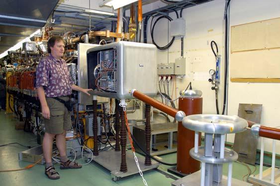
17 Nanometer stabilisation Latest stabilization technology applied to the accelerator field The most stable place on earth!!! Stabilizing quadrupoles to the 0.5 nm level! (up to 10 times better than supporting ground, above 4 Hz) J.P.Delahaye Universite de Geneve
18 Beam sizes at Collisions Vertical Beam Size (nm) CLIC 3000 CLIC 1000 FFTB NLC 1000 CLIC 500 NLC 500 SLC TESLA 500 TESLA Horizontal Beam Size (nm) J.P.Delahaye Universite de Geneve
19 Luminosity Spectrum Energy (TeV) L in 1% E cm 71% 56% 30% 25% L in 5% E cm 87% 71% 42% 34% Momentum spread after collision increases with colliding beam energy. Substantial luminosity from particles within small momentum spread. J.P.Delahaye Universite de Geneve
20 CLIC PHYSICS STUDY GROUP (Convener: A.De Roeck) From April in response to a growing interest in the physics potential of a multi-tev e+e- collider - a CLIC Physics Study Group has been set-up in order to: 1) Identify and investigate key processes that can help to optimize the machine design: luminosity spectrum, accelerator induced background, beam-beam background 2) Explore the physics program for CLIC and define a concept of the detector 3) Make a comparative assessment of the CLIC physics potential Report summarizing the physics potentials of a facility operating at a centre-ofmass energy from 1 to 5 TeV with luminosities in the order of cm -1 sec -2. Physics at the CLIC Multi-TeV Linear Collider : CERN J.P.Delahaye Universite de Geneve
21 The CLIC main challenges COMMON TO MULTI-TEV LINEAR COLLIDERS SPECIFIC TO THE CLIC TECHNOLOGY Accelerating gradient Generation and preservation of ultra-low emittance beams Beam Delivery & IP issues: nanometer size beams Sub-nanometer component stabilisation Physics with colliding beams in high beamstrahlung regime 30 GHz components with manageable wakefields Efficient RF power production by Two Beam Acceleration Operability at high power (beam losses) and linac environment (RF switch) addressed in Test Facilities J.P.Delahaye Universite de Geneve
22 Drive Beam Accelerator efficient acceleration in low frequency fully loaded linac powered by 450 low frequency high efficiency klystrons 50 Mwatts/100 µs The CLIC RF Power Source Delay Loop 2 gap creation, pulse compression & frequency multiplication RF Transverse Deflectors Combiner Ring 4 Combiner Ring 4 pulse compression & frequency multiplication Drive Beam Decelerator Section (22 in total) pulse compression & frequency multiplication Beam frequency multiplication and power compression by 32 Drive beam time structure - initial 30 GHz RF Power Extraction 68 GeV/c energy gain 624 m long Return Arc Bunch Compression Drive beam time structure - final 130 ns 130 ns 4.2 µs 100 µs train length sub-pulses 4.6 A 2 GeV - 64 cm between bunches J.P.Delahaye Universite de Geneve pulses A - 2 cm between bunches 22
23 What does the RF power Source do? The CLIC RF power source can be described as a black box, combining very long RF pulses, and transforming them in many short pulses, with higher power and with higher frequency 450 MBK Klystrons Low frequency High efficiency Power stored in electron beam Power extracted from beam in resonant structures Accelerating Structures High Frequency High field Long RF Pulses P 0, ν 0, τ 0 Electron beam manipulation Power compression Frequency multiplication Short RF Pulses P A = P 0 N 1 τ A = τ 0 / N 2 ν A = ν 0 N 3 J.P.Delahaye Universite de Geneve
24 Power flow from the grid to the beam Wall Plug 937 MHz RF Beam 30 GHz RF pulses of 250 MWatts *100 nsec J.P.Delahaye Universite de Geneve
 Toshiba MBK E-3736 6 beams, 10 MW, 1.")
25 Improving the efficiency Wall plug: 300 MW Wall plug: 230 MW Wall Plug & 30 GHz RF power in CLIC 1 GHz Klystron: 65% & Modulator: 90% 30 GHz: 120 MW New klystron development drive beam acceleration, manipulation & 30 GHZ RF power extraction 1 GHz Klystron: 80% & Modulator: 95% 30 GHz: 120 MW Efficiency, % CLIC MBK 30 beams, 50 MW, GHz (proposal) Toshiba MBK E beams, 10 MW, 1.3 GHz (project) Why Multi Beam? Low perveance (A/V 3/2 ) favor klystron efficiency. Multi Beam devices keep single beam perveance small to provide high efficiencies for high RF power output (tens of MW). Thales MBK TH beams, 10 MW, 1.3 GHz (measured) Perveance (A/V 3/2 ) x10-6 State-of-the-art klystron efficiencies vs. perveance for single beam multi-beam J.P.Delahaye Universite de Geneve
26 CTF2 goals : C L I C CLIC Test Facility (CTF2) RF gun to demonstrate feasibility of CLIC two-beam acceleration scheme to study generation of short, intense e-bunches using laser-illuminated PCs in RF guns to demonstrate operability of µ-precision active-alignment system in accelerator environment to provide a test bed to develop and test accelerator diagnostic equipment to provide high power 30 GHz RF power source for high gradient testing ~90 MW 16 ns pulses All-but-one of 30 GHz two-beam modules removed in 2000 to create a high-gradient test stand GHz TWS GHz TWS Idler cavity bunch compressor 48 bunches 1-14 nc MeV σ=0.6 mm CTF2 four 30 GHz power extracting structures spectrometers RF gun 3 GHz TW structure 1 bunch 0.6 nc 45 MeV σ=0.9 mm five 30 GHz accelerating structures laser train generator configuration of m J.P.Delahaye Universite de Geneve

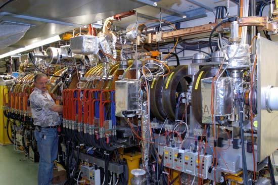
27 Two Beams set-up in CTF2 CTF II 30GHz MODULES Drive beam line Main beam line J.P.Delahaye Universite de Geneve

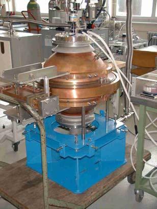
28 Power ExTraction Structure (PETS) Damping slots Broadband RF load Quarter geometry of C-PETS Circularly-symmetric Large aperture (25 mm) Very shallow sinus-type corrugations Eight 1 mm-wide damping slots Table 1. Parameters of the C-PETS. Beam chamber diameter, mm 25 Synch. mode frequency, GHz Synch. mode β g 0.85 c Synch. mode R /Q, Ω/m 244 Synch. mode Q-factor Peak transverse wakefield V/pC/m/mm 0.83 Transverse mode Q-factor (damped) < cm length of this structure produces about 560 MW of 30 GHz RF power enough to drive two CLIC accelerating structures J.P.Delahaye Universite de Geneve


29 Accelerating structure developments CONTROL OF TRANSVERSE WAKEFIELDS short-range wakes BNS damping long-range wakes damping and detuning + beam-based trajectory correction, ε bump For wake suppression - work still focused on here. Each cell is damped by 4 radial WGs terminated by waveguide-damped structures of type shown discrete SiC RF loads. 15 GHz model tested in ASSET Excellent agreement obtained between theory and experiment believe we can solve damping problem cell ASSET test results SiC load Damping WG J.P.Delahaye Universite de Geneve
 seem to suffer severe surface damage.")
 Investigating new materials that are resistant to arcing - tungsten looks promising J.P.")
30 Structure breakdown and damages High-power tests of copper accelerating structures indicates that for RF pulses >10 ns, the maximum surface field that can be obtained with copper is always around MV/m. At these field levels structures with large apertures (or rather with large a/λ ratios) seem to suffer severe surface damage. 1 mm Microscopic image of damaged iris Damaged iris longitudinal cut The CLIC study group is adopting a two-pronged approach to solving the breakdown problem Modify the RF design to obtain lower surface field to accelerating field ratio (Es/Ea ~ 2) Investigating new materials that are resistant to arcing - tungsten looks promising J.P.Delahaye Universite de Geneve


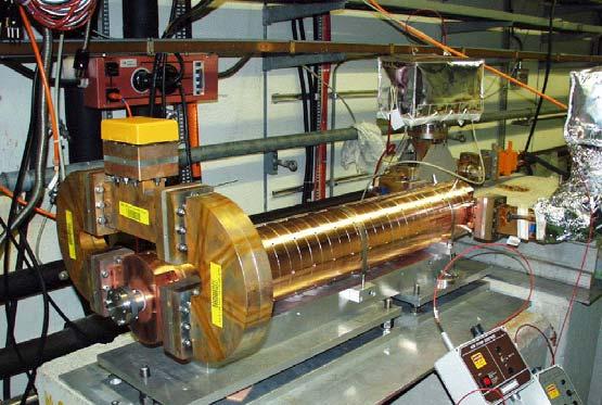
31 Tests of tungsten iris in CTF2 Irises after high-gradient testing to about the same field level Copper - damaged Test structure in external vacuum can, with clamped coupler cell Tungsten - undamaged Copper iris replaced by Tungsten iris J.P.Delahaye Universite de Geneve
 200 new design copper 30 cell clamped tungsten-iris")

32 Achieved accelerating fields in CTF2 High gradient tests of new structures with molybdenum irises reached 190 MV/m peak accelerating gradient without any damage well above the nominal CLIC accelerating field of 150 MV/m but with RF pulse length of 16 ns only (nominal 100 ns) 200 new design copper 30 cell clamped tungsten-iris structure Peak Accelerating field (MV/m) old design copper new design tungsten 3.5 mm tungsten iris mm tungsten iris after ventilation 3.5 mm copper structure 3.5 mm molybdenum structure CLIC goal loaded CLIC goal unloaded No. of shots x 10 6 A world record!!! J.P.Delahaye Universite de Geneve
33 Accelerating fields in Linear Colliders Accelerating fields in Linear Colliders 250 Mean accelerating field (MV/m) CLIC achieved NLC CLIC nominal JLC-C SLC TESLA 800 TESLA E+01 1.E+02 1.E+03 1.E+04 1.E+05 1.E+06 1.E+07 RF pulse duration (nanosec) J.P.Delahaye Universite de Geneve


34 RF pulse heating experiment The fatigue limit of cooper surface due to cyclic pulsed heating is being tested with an experimental setup based on 30 GHz FEM in Dubna, JINR. RF accessories designed and manufactured in Nizny Novgorod, IAP. 30 GHz, 25 MW, 200 ns RF pulse General views of the experimental setup Test H 012 cavity J.P.Delahaye Universite de Geneve
35 International Technical Review Committee Review of the various Linear Colliders studies requested by ICFA (February 2001) ILC-TRC Report (2003) Status of various studies (TESLA, JLC-C/X, NLC, CLIC) Ranking of R&D topics still to be made for each study R1: R&D needed for feasibility demonstration R2: R&D needed to finalize design choices R3: R&D needed before starting production R4: R&D desirable for technical/cost optimisation J.P.Delahaye Universite de Geneve
36 Key issues common to all Linear Colliders studies independently of the chosen technology R1: Feasibility: None R2: Design finalisation (9) Generation of ultra low emittances in Damping-ring (4) Electron cloud effects (also ATF, LHC) Fast ion instability Stability to < 10-3 of extraction kickers Emittance correction Low-emittance measurement and transport (3) Static tuning, including dynamic effects Beam instrumentation (intra-train L monitors, laser-wire profile monitors) On-girder sources of vibration Reliability (2) Evaluation of the reliability of critical subsystems, acceptable failure rate Beam based tuning procedures to align magnets and structures, in presence of beam and components errors More difficult in CLIC because of larger wakefields, smaller beam emittances and smaller beam sizes at IP J.P.Delahaye Universite de Geneve
37 R1: Feasibility CLIC technology-related key issues as pointed out by ILC-TRC R1.1: Test of damped accelerating structure at design gradient and pulse length R1.2: Validation of drive beam generation scheme with fully loaded linac operation R1.3: Design and test of damped ON/OFF power extraction structure R2: Design finalisation R2.1: Developments of structures with hard-breaking materials (W, Mo ) R2.2: Validation of stability and losses of drive beam decelerator; Design of machine protection system R2.3: Test of relevant linac sub-unit with beam R2.4: Validation of Multi-Beam Klystron with long RF pulse R2.5: Effects of coherent synchrotron radiation in bunch compressors R2.6 Design of an extraction line for 3 TeV c.m. Valid for any Multi-TeV Linear Collider independently of the technology J.P.Delahaye Universite de Geneve
38 Strategy Key issues common to all Linear Collider studies independently of the chosen technology: Collaboration with other Linear Collider studies and with European Laboratories in the frame of a Design Study proposed for funding by EU Framework Programme (FP6) Key issues specific to CLIC technology: Focus of the CLIC study All R1 (feasibility) and R2 (design finalisation) key issues addressed in new test facility: CTF3 except the Multi-Beam Klystron (MBK) which does not require R&D but development by industry (feasibility study already done) J.P.Delahaye Universite de Geneve

39 EUROTEV ( ) EU supported (9MEuros) Linear Colliders Design Study About common L.C. key issues J.P.Delahaye Universite de Geneve
40 27 collaborating institutes J.P.Delahaye Universite de Geneve
41 All R1 and R2 CLIC key issues addressed in CLIC Test Facility (CTF3) Test of Drive Beam Generation, Acceleration & RF Multiplication by a factor 10 Two Beam RF power generation & component tests with nominal fields & pulse length FULLY LOADED 3 GHZ ACCELERATION 3.5 A µs PULSE COMPRESSION FREQUENCY MULTIPLICATION 30 GHz MW ns 30 GHZ POWER EXTRACTION & COMPONENTS TEST 35 A ns RF DEFLECTORS J.P.Delahaye Universite de Geneve
42 CLIC Test Facility: CTF3 Collaboration CERN INFN LAL NWU RAL SLAC -Uppsala Damped accelerating structure (R1.1) INFN 2007 CLEX Stability bench marking (R2.1) CLIC sub-unit (R2.3) 2006 Drive beam generation scheme (R1.2) ON/OFF PETS (R1.3) J.P.Delahaye Universite de Geneve
 Beam Current 0.")
43 CTF3 - PRELIMINARY PHASE low-charge demonstration of electron pulse combination and bunch frequency multiplication by up to factor 5 Beam power and frequency multiplication Streak camera image of beam time structure evolution 1 st turn streak camera measurement RF deflectors 333 ps 2 nd 3 rd Beam time structure in linac Bunch spacing 333 ps 4 th 420 ns (ring revolution time) Beam Current 0.3 A 5 th turn 66 ps Beam Current 1.2 A Bunch spacing 66 ps Beam structure after combination time J.P.Delahaye Universite de Geneve
")
44 CTF3 Injector installation 7A Thermionic Gun (LAL-SLAC) Bunchers(LAL)&Solenoids(SLACstudy) Bunch length adjustment with magnetic chicane Accelerating structure with full beam loading Novel RF power compression with Barrel Open Cavity (BOC) J.P.Delahaye Universite de Geneve
! Beam stable!")
45 Nominal Beam parameters reached Injector commissioning 2003 Nominal Achieved I 3.5 A 4.5 A τ p 1.5 µs 1.5 µs E 20 MeV 20 MeV ε n,rms 100 π mm mrad π mm mrad Full Beam Loading demonstrated: >95 % efficiency! More than with Superconducting systems (when including cryogenics)! Beam stable! τ bunch,rms 5 ps < 6.5 ps First demonstration of full beam loading Output power from accelerating structure 1.6 µs compressed RF pulse Beam off ~ 24 MW Beam on ~ 0 MW 1.5 µs SiC wedges Damped DBA structure st 31 disc 4.2 A Coupler cell (2 waveguide ports) total length: 1.10 m dimple tuning holes J.P.Delahaye Universite de Geneve R. Corsini 18/08/2003

46 High-gradient test stand, CTF2 Two beam test stand Two-beam 30 GHz power production in CTF3 High-power transfer line CTF3 linac PETs branch J.P.Delahaye Universite de Geneve
 J.P.")
47 Bunch Compressor and Delay Loop C L I C (design, construction, resources by INFN-LNF) J.P.Delahaye Universite de Geneve
48 Work packages WP GHz High Gradient Test Stand WP 4 Probe Beam WP 1 Combiner Ring and Transfer Lines Test Beam Line WP 6 Relevant linac subunit Two-beam test stand WP 5 WP 2.2 CLEX Building WP 3 J.P.Delahaye Universite de Geneve
49 Extended collaboration C L I C Laboratories and Institutions are invited to contribute to this programme by: taking full responsibility for part, complete of one or several work-packages providing voluntary contributions a la carte in cash, in kind and/or in man-power Multilateral collaboration network of volunteer institutes (from which CERN is one of them) participating jointly to the technical coordination and management of the project. Expression of Interest from 12 Institutes at CLIC Collaboration Meeting (19/05/04) Commitment of laboratories and discussion of MoU Collaboration Agreement on 28/01/05 J.P.Delahaye Universite de Geneve
50 Schedule with extra resources Drive Beam Accelerator 30 GHz power test stand in Drive Beam accelerator 30 GHz power testing (4 months per year) R1.1 feasibility test of CLIC structure Delay Loop Combiner Ring R1.2 feasibility test of Drive beam generation CLIC Experimental Area (CLEX) R1.3 feasibility test PETS Probe Beam R2.2 feasibility test representativeclic linac section Test beam line R2.1 Beam stability bench mark tests J.P.Delahaye Universite de Geneve
51 Tentative long-term CLIC scenario Shortest and technically limited schedule Technology evaluation and Physics assessment based on LHC results for a possible decision on Linear Collider funding with staged construction starting with the lowest energy required by Physics Feasibility issues R1 (TRC) R&D Issues R2 (TRC) and Conceptual Design R&D Issues R3 & R4 (TRC) and Technical Design Engineering Optimisation and Project Approval Construction (possibly in stages) J.P.Delahaye Universite de Geneve
52 CONCLUSION CLIC only possible scheme to extend Linear Collider energy into the Multi-TeV range CLIC technology not mature yet, requires challenging R&D A development: complementary to Super-Conducting technology recently down-selected by ITRP for a TeV Linear Collider necessary in order to extend energy range of LC in the future Very promising performances already demonstrated in CTF2 Remaining key issues clearly identified (ILC-TRC) L.C. Key-issues independent of the technology studied by 2008 in a wide collaboration of European Institutes (Design Study submitted to EU FP6 funding) CLIC-related key-issues addressed in CTF3 (feasibility by 2007 and design finalisation by 2009) if extra resources can be found J.P.Delahaye Universite de Geneve
53 CONCLUSION Provides the High Energy Physics community with the information about the feasibility of CLIC technology for Linear Collider in due time when Physics needs will be fully determined following LHC results Safety net to the Super-Conducting technology in case sub-tev energy range is not considered attractive enough for Physics Possible construction in stages starting with low energy applications A lot still to be done before the CLIC technology can be made operational; Novel Ideas and Challenging work in world-wide collaborations needed YOU ARE ALL WELCOME to participate and make the CLIC scheme and technology a realistic tool in the best interest of Physics J.P.Delahaye Universite de Geneve
54 References Scaling laws for e+/e- Linear Colliders: NIM A421 (1999) p A 3 TeV e+/e- Linear Collider based on CLIC technology: CERN CTF3 Design Report: CERN/PS CLIC contribution to the Technical Review Committee on a 500 GeV e+/e- Linear Collider: CERN Physics at the CLIC Multi-TeV Linear Collider: CERN J.P.Delahaye Universite de Geneve
Recent Progress at the CLIC Test Facility 3 at CERN
 Recent Progress at the CLIC Test acility 3 at CERN P. Urschütz Talk outline Introduction to the CLIC two-beam scheme The CLIC Test acility CT3 Results from CT3 Past Recent Results Outlook on future activities
Short Introduction to CLIC and CTF3, Technologies for Future Linear Colliders
 Short Introduction to CLIC and CTF3, Technologies for Future Linear Colliders Explanation of the Basic Principles and Goals Visit to the CTF3 Installation Roger Ruber Collider History p p hadron collider
CLIC THE COMPACT LINEAR COLLIDER
 CLIC THE COMPACT LINEAR COLLIDER Emmanuel Tsesmelis Directorate Office, CERN 9 th Corfu Summer Institute 4 September 2009 1 THE CLIC ACCELERATOR 2 Linear Collider Baseline LEP: 209 GeV next Electron-Positron
Status of linear collider designs:
 Status of linear collider designs: Main linacs Design overview, principal open issues G. Dugan March 11, 2002 Linear colliders: main linacs The main linac is the heart of the linear collider TESLA, NLC/JLC,
The TESLA Dogbone Damping Ring
 The TESLA Dogbone Damping Ring Winfried Decking for the TESLA Collaboration April 6 th 2004 Outline The Dogbone Issues: Kicker Design Dynamic Aperture Emittance Dilution due to Stray-Fields Collective
CLIC Detector studies status + plans
 CLIC Detector studies status + plans Contents: - Introduction to CLIC accelerator - 2004 CLIC Study group report: "Physics at the CLIC Multi-TeV Linear Collider - CERN participation in Linear Collider
Report from the Luminosity Working Group of the International Linear Collider Technical Review Committee (ILC-TRC) Chairman: Greg Loew
 Chairman: Greg Loew") Report from the Luminosity Working Group of the International Linear Collider Technical Review Committee (ILC-TRC) Chairman: Greg Loew The ILC-TRC was originally constituted in 1994 and produced a report
Report from the Luminosity Working Group of the International Linear Collider Technical Review Committee (ILC-TRC) Chairman: Greg Loew The ILC-TRC was originally constituted in 1994 and produced a report
THE CLIC PROJECT - STATUS AND PROSPECTS
 THE CLIC PROJECT - STATUS AND PROSPECTS E. Adli, University of Oslo, Norway On behalf of the CLIC/CTF3 collaboration Abstract Following the feasibility demonstration of the novel CLIC technology and the
On the future plan of KEK for ILC(International Linear Collider) Junji Urakawa(KEK) Contents
 Junji Urakawa(KEK) Contents") On the future plan of KEK for ILC(International Linear Collider) Junji Urakawa(KEK) 2004.10.24 Contents 0. Outline until now. Review of SC-LC(TESLA) and R&D items. R&D Items at ATF. R&D plans for Superconducting
On the future plan of KEK for ILC(International Linear Collider) Junji Urakawa(KEK) 2004.10.24 Contents 0. Outline until now. Review of SC-LC(TESLA) and R&D items. R&D Items at ATF. R&D plans for Superconducting
PARTICLE BEAMS, TOOLS FOR MODERN SCIENCE AND MEDICINE Hans-H. Braun, CERN
 5 th Particle Physics Workshop National Centre for Physics Quaid-i-Azam University Campus, Islamabad PARTICLE BEAMS, TOOLS OR MOERN SCIENCE AN MEICINE Hans-H. Braun, CERN 3 rd Lecture Introduction to Linear
e + e - Linear Collider
 e + e - Linear Collider Disclaimer This talk was lifted from an earlier version of a lecture by N.Walker Eckhard Elsen DESY DESY Summer Student Lecture 3 rd August 2006 1 Disclaimer II Talk is largely
ILC Beam Dynamics Studies Using PLACET
 ILC Beam Dynamics Studies Using PLACET Andrea Latina (CERN) July 11, 2007 John Adams Institute for Accelerator Science - Oxford (UK) Introduction Simulations Results Conclusions and Outlook PLACET Physical
Accelerator R&D Opportunities: Sources and Linac. Developing expertise. D. Rubin, Cornell University
 Accelerator R&D Opportunities: Sources and Linac D. Rubin, Cornell University Electron and positron sources Requirements Status of R&D Linac Modeling of beam dynamics Development of diagnostic and tuning
The International Linear Collider. Barry Barish Caltech 2006 SLUO Annual Meeting 11-Sept-06
 The International Linear Collider Barry Barish Caltech 2006 SLUO Annual Meeting 11-Sept-06 Why e + e - Collisions? elementary particles well-defined energy, angular momentum uses full COM energy produces
X-band high-gradient and CLIC R&D for future colliders
 Talk outline The work plan issues, organization & timescale Recent R&D results High-gradient structures CTF3 Other R&D activities Beam physics Technical issues Conclusion X-band high-gradient and CLIC
Current and Future Developments in Accelerator Facilities. Jordan Nash, Imperial College London
 Current and Future Developments in Accelerator Facilities Jordan Nash, Imperial College London Livingston chart (circa 1985) Nearly six decades of continued growth in the energy reach of accelerators Driven
COMBINER RING LATTICE
 CTFF3 TECHNICAL NOTE INFN - LNF, Accelerator Division Frascati, April 4, 21 Note: CTFF3-2 COMBINER RING LATTICE C. Biscari 1. Introduction The 3 rd CLIC test facility, CTF3, is foreseen to check the feasibility
WG2 on ERL light sources CHESS & LEPP
 Charge: WG2 on ERL light sources Address and try to answer a list of critical questions for ERL light sources. Session leaders can approach each question by means of (a) (Very) short presentations (b)
THE ACTIVE PREALIGNMENT OF THE CLIC COMPONENTS H. MAINAUD DURAND, T. TOUZE CERN
 THE ACTIVE PREALIGNMENT OF THE CLIC COMPONENTS H. MAINAUD DURAND, T. TOUZE CERN Overview Introduction : the CLIC study The alignment of CLIC Steps of alignment The active prealignment The situation of
High average current photo injector (PHIN) for the CLIC Test Facility at CERN
 for the CLIC Test Facility at CERN") High average current photo injector (PHIN) for the CLIC Test Facility at CERN CLIC and CTF3 motivation Photo injectors, PHIN Emittance measurements Long pulse operation, time resolved measurements Cathode
High average current photo injector (PHIN) for the CLIC Test Facility at CERN CLIC and CTF3 motivation Photo injectors, PHIN Emittance measurements Long pulse operation, time resolved measurements Cathode
Introduction. Thermoionic gun vs RF photo gun Magnetic compression vs Velocity bunching. Probe beam design options
 Introduction Following the 19/05/04 meeting at CERN about the "CTF3 accelerated programme", a possible french contribution has been envisaged to the 200 MeV Probe Beam Linac Two machine options were suggested,
ILC concepts / schematic
 INFN School on Electron Accelerators 12-14 September 2007, INFN Sezione di Pisa Lecture 1a ILC concepts / schematic Carlo Pagani University of Milano INFN Milano-LASA & GDE The Standard Model Fundamental
The CLIC Study. R. Aßmann. Lecture to the CERN summer students. 28 July 2004 CERN AB/ABP
 The CLIC Study Lecture to the CERN summer students 28 July 2004 R. Aßmann CERN AB/ABP For the CLIC Study Team Acknowledgements to R. Corsini, J.P. Delahaye, G. Guignard, S. Redaelli, D. Schulte, F. Tecker,
CLIC Project Status. Roger Ruber. Uppsala University. On behalf of the CLIC Collaborations. Thanks to all colleagues for materials
 CLIC Project Status Roger Ruber Uppsala University On behalf of the CLIC Collaborations Thanks to all colleagues for materials IAS 2018 Program on High Energy Physics Hong Kong, 23 January 2018 CLIC Collaborations
Status and Future Prospects
 Status and uture Prospects for CLIC Introduction CLIC design CLIC Test acility (CT 3) results Outlook and Conclusions Steffen öbert, LINAC 08, 29.9-3.10, 2008, Victoria, Canada Introduction CLIC = Compact
III. CesrTA Configuration and Optics for Ultra-Low Emittance David Rice Cornell Laboratory for Accelerator-Based Sciences and Education
 III. CesrTA Configuration and Optics for Ultra-Low Emittance David Rice Cornell Laboratory for Accelerator-Based Sciences and Education Introduction Outline CESR Overview CESR Layout Injector Wigglers
ThomX Machine Advisory Committee. (LAL Orsay, March ) Ring Beam Dynamics
 Ring Beam Dynamics") ThomX Machine Advisory Committee (LAL Orsay, March 20-21 2017) Ring Beam Dynamics A. Loulergue, M. Biagini, C. Bruni, I. Chaikovska I. Debrot, N. Delerue, A. Gamelin, H. Guler, J. Zang Programme Investissements
ThomX Machine Advisory Committee (LAL Orsay, March 20-21 2017) Ring Beam Dynamics A. Loulergue, M. Biagini, C. Bruni, I. Chaikovska I. Debrot, N. Delerue, A. Gamelin, H. Guler, J. Zang Programme Investissements
Towards a Multi TeV Linear Collider; Drive Beam Generation with CTF3
 Towards a Multi TeV Linear Collider; rive Beam Generation with CT3 H.H. Braun / CERN, on behalf of the CT3 collaboration Introduction CLIC & CT3 CT3 status and achievements CT3 outlook CLIC aim: develop
A 6 GeV Compact X-ray FEL (CXFEL) Driven by an X-Band Linac
 Driven by an X-Band Linac") A 6 GeV Compact X-ray FEL (CXFEL) Driven by an X-Band Linac Zhirong Huang, Faya Wang, Karl Bane and Chris Adolphsen SLAC Compact X-Ray (1.5 Å) FEL Parameter symbol LCLS CXFEL unit Bunch Charge Q 250 250
A 6 GeV Compact X-ray FEL (CXFEL) Driven by an X-Band Linac Zhirong Huang, Faya Wang, Karl Bane and Chris Adolphsen SLAC Compact X-Ray (1.5 Å) FEL Parameter symbol LCLS CXFEL unit Bunch Charge Q 250 250
BEAM TESTS OF THE LHC TRANSVERSE FEEDBACK SYSTEM
 JINR BEAM TESTS OF THE LHC TRANSVERSE FEEDBACK SYSTEM W.Höfle, G.Kotzian, E.Montesinos, M.Schokker, D.Valuch (CERN) V.M. Zhabitsky (JINR) XXII Russian Particle Accelerator Conference 27.9-1.1. 21, Protvino
SPPS: The SLAC Linac Bunch Compressor and Its Relevance to LCLS
 LCLS Technical Advisory Committee December 10-11, 2001. SPPS: The SLAC Linac Bunch Compressor and Its Relevance to LCLS Patrick Krejcik LCLS Technical Advisory Committee Report 1: July 14-15, 1999 The
High-gradient X-band RF technology for CLIC and beyond
 High-gradient X-band RF technology for CLIC and beyond Philip Burrows 1 Oxford University Oxford, UK E-mail: Philip.Burrows@physics.ox.ac.uk Walter Wuensch CERN Geneva, Switzerland E-mail: Walter.Wuensch@cern.ch
1.1 Report on the First ILC Workshop, KEK (Japan) November 04
 November 04") 5 1.1 Report on the First ILC Workshop, KEK (Japan) November 04 1.1.1 Introduction Susanna Guiducci mail to: Susanna.Guiducci@lnf.infn.it LNF-INFN, Frascati, Italy The First International Linear Collider
5 1.1 Report on the First ILC Workshop, KEK (Japan) November 04 1.1.1 Introduction Susanna Guiducci mail to: Susanna.Guiducci@lnf.infn.it LNF-INFN, Frascati, Italy The First International Linear Collider
CERN EUROPEAN ORGANIZATION FOR NUCLEAR RESEARCH CTF3 DRIVE BEAM INJECTOR OPTIMISATION
 CERN EUROPEAN ORGANIZATION FOR NUCLEAR RESEARCH CLIC Note 1060 CTF3 DRIVE BEAM INJECTOR OPTIMISATION - 1 Sh. Sanaye Hajari 1, 2, * H. Shaker 1, 2 and S. Doebert 2 Institute for Research in Fundamental
Tools of Particle Physics I Accelerators
 Tools of Particle Physics I Accelerators W.S. Graves July, 2011 MIT W.S. Graves July, 2011 1.Introduction to Accelerator Physics 2.Three Big Machines Large Hadron Collider (LHC) International Linear Collider
Impedance & Instabilities
 Impedance & Instabilities The concept of wakefields and impedance Wakefield effects and their relation to important beam parameters Beam-pipe geometry and materials and their impact on impedance An introduction
X-band Experience at FEL
 X-band Experience at FERMI@Elettra FEL Gerardo D Auria Elettra - Sincrotrone Trieste GdA_TIARA Workshop, Ångström Laboratory, June 17-19, 2013 1 Outline The FERMI@Elettra FEL project Machine layout and
Emittance preservation in TESLA
 Emittance preservation in TESLA R.Brinkmann Deutsches Elektronen-Synchrotron DESY,Hamburg, Germany V.Tsakanov Yerevan Physics Institute/CANDLE, Yerevan, Armenia The main approaches to the emittance preservation
EUROPEAN ORGANIZATION FOR NUCLEAR RESEARCH CERN - SL DIVISION. Multi-TeV CLIC Photon Collider Option. H. Burkhardt
 EUROPEAN ORGANIZATION FOR NUCLEAR RESEARCH CERN - SL DIVISION CERN-SL-2000-070 CLIC Note 463 AP Multi-TeV CLIC Photon Collider Option H. Burkhardt Considerations for an option of γγ collisions at multi-tev
Proton-driven plasma wakefield acceleration
 Proton-driven plasma wakefield acceleration Matthew Wing (UCL) Motivation : particle physics; large accelerators General concept : proton-driven plasma wakefield acceleration Towards a first test experiment
SLS at the Paul Scherrer Institute (PSI), Villigen, Switzerland
, Villigen, Switzerland") SLS at the Paul Scherrer Institute (PSI), Villigen, Switzerland Michael Böge 1 SLS Team at PSI Michael Böge 2 Layout of the SLS Linac, Transferlines Booster Storage Ring (SR) Beamlines and Insertion Devices
SLS at the Paul Scherrer Institute (PSI), Villigen, Switzerland Michael Böge 1 SLS Team at PSI Michael Böge 2 Layout of the SLS Linac, Transferlines Booster Storage Ring (SR) Beamlines and Insertion Devices
Linac Driven Free Electron Lasers (III)
") Linac Driven Free Electron Lasers (III) Massimo.Ferrario@lnf.infn.it SASE FEL Electron Beam Requirements: High Brightness B n ( ) 1+ K 2 2 " MIN r #$ % &B! B n 2 n K 2 minimum radiation wavelength energy
Linac Driven Free Electron Lasers (III) Massimo.Ferrario@lnf.infn.it SASE FEL Electron Beam Requirements: High Brightness B n ( ) 1+ K 2 2 " MIN r #$ % &B! B n 2 n K 2 minimum radiation wavelength energy
CERN - European Laboratory for Particle Physics / ~2»~7. CLIC Study Annual Report summarised by I. Wilson for the CLIC Study Group
 65 CLl(,-l\}OT - $"L?l B wj l I CERN - European Laboratory for Particle Physics / ~2»~7 CLIC Note 327 17.02.97 OCR Output CLIC Study Annual Report 1996 summarised by I. Wilson for the CLIC Study Group
LHC Luminosity and Energy Upgrade
 LHC Luminosity and Energy Upgrade Walter Scandale CERN Accelerator Technology department EPAC 06 27 June 2006 We acknowledge the support of the European Community-Research Infrastructure Activity under
VELA/CLARA as Advanced Accelerator Studies Test-bed at Daresbury Lab.
 VELA/CLARA as Advanced Accelerator Studies Test-bed at Daresbury Lab. Yuri Saveliev on behalf of VELA and CLARA teams STFC, ASTeC, Cockcroft Institute Daresbury Lab., UK Outline VELA (Versatile Electron
4GLS Status. Susan L Smith ASTeC Daresbury Laboratory
 4GLS Status Susan L Smith ASTeC Daresbury Laboratory Contents ERLP Introduction Status (Kit on site ) Plan 4GLS (Conceptual Design) Concept Beam transport Injectors SC RF FELs Combining Sources May 2006
Overview of Linear Collider Designs
 Overview of Linear Collider Designs SLAC-PUB-6244 April 1993 (4 R. H. Siemann Stanford Linear Accelerator Center, Stanford University, Stanford, CA 94309 I. INTRODUCTION Linear collider design and development
Beam-beam Effects in Linear Colliders
 Beam-beam Effects in Linear Colliders Daniel Schulte D. Schulte Beam-beam effects in Linear Colliders 1 Generic Linear Collider Single pass poses luminosity challenge Low emittances are produced in the
CERN EUROPEAN ORGANIZATION FOR NUCLEAR RESEARCH THE CLIC POSITRON CAPTURE AND ACCELERATION IN THE INJECTOR LINAC
 CERN EUROPEAN ORGANIZATION FOR NUCLEAR RESEARCH CLIC Note - 819 THE CLIC POSITRON CAPTURE AND ACCELERATION IN THE INJECTOR LINAC A. Vivoli 1, I. Chaikovska 2, R. Chehab 3, O. Dadoun 2, P. Lepercq 2, F.
Status of linear collider designs:
 Status of linear collider designs: Electron and positron sources Design overview, principal open issues G. Dugan March 11, 2002 Electron sourcesfor 500 GeV CM machines Parameter TESLA NLC CLIC Cycle rate
Lattice Design and Performance for PEP-X Light Source
 Lattice Design and Performance for PEP-X Light Source Yuri Nosochkov SLAC National Accelerator Laboratory With contributions by M-H. Wang, Y. Cai, X. Huang, K. Bane 48th ICFA Advanced Beam Dynamics Workshop
The CLIC active prealignment studies H. MAINAUD DURAND, T. TOUZE CERN
 The CLIC active prealignment studies H. MAINAUD DURAND, T. TOUZE CERN Overview The alignment of CLIC Steps of alignment The active prealignment The situation of the studies on the active prealignment Studies
Thanks to all Contributors
 Thanks to all Contributors High Gradient versus High Field Dr. José Miguel Jiménez CERN Technology Department Head CERN-Spain Liaison Officer 2 Main topics A worldwide success? Full exploitation of the
AWAKE: The Proton Driven Plasma Wakefield Acceleration Experiment at CERN. Alexey Petrenko on behalf of the AWAKE Collaboration
 AWAKE: The Proton Driven Plasma Wakefield Acceleration Experiment at CERN Alexey Petrenko on behalf of the AWAKE Collaboration Outline Motivation AWAKE at CERN AWAKE Experimental Layout: 1 st Phase AWAKE
LC Commissioning, Operations and Availability
 International Technology Recommendation Panel X-Band Linear Collider Path to the Future LC Commissioning, Operations and Availability Tom Himel Stanford Linear Accelerator Center April 26-27, 2004 Integrating
Overview on Compton Polarimetry
 General Issues O spin motion & alignment tolerances O beam-beam effects & upstream vs. Downstream Compton Polarimetry Basics O beam parameters & Compton detection methods O kinematics, cross sections &
Critical R&D Issues for ILC Damping Rings and New Test Facilities
 Critical R&D Issues for ILC Damping Rings and New Test Facilities Andy Wolski Cockcroft Institute/University of Liverpool PAC 2007, Albuquerque, New Mexico. 1 ILC Key Parameters Given the main linac parameters:
CLIC polarized e+ source based on laser Compton scattering
 CLIC polarized e+ source based on laser Compton scattering Frank Zimmermann CLIC Meeting, 16. December 2005 Thanks to Eugene Bulyak, Masao Kuriki, Klaus Moenig, Tsunehiko Omori, Junji Urakawa, Alessandro
LCLS Accelerator Parameters and Tolerances for Low Charge Operations
 LCLS-TN-99-3 May 3, 1999 LCLS Accelerator Parameters and Tolerances for Low Charge Operations P. Emma SLAC 1 Introduction An option to control the X-ray FEL output power of the LCLS [1] by reducing the
Diagnostic Systems for Characterizing Electron Sources at the Photo Injector Test Facility at DESY, Zeuthen site
 1 Diagnostic Systems for Characterizing Electron Sources at the Photo Injector Test Facility at DESY, Zeuthen site Sakhorn Rimjaem (on behalf of the PITZ team) Motivation Photo Injector Test Facility at
Experimental Measurements of the ORION Photoinjector Drive Laser Oscillator Subsystem
 Experimental Measurements of the ORION Photoinjector Drive Laser Oscillator Subsystem D.T Palmer and R. Akre Laser Issues for Electron RF Photoinjectors October 23-25, 2002 Stanford Linear Accelerator
ASTRA simulations of the slice longitudinal momentum spread along the beamline for PITZ
 ASTRA simulations of the slice longitudinal momentum spread along the beamline for PITZ Orlova Ksenia Lomonosov Moscow State University GSP-, Leninskie Gory, Moscow, 11999, Russian Federation Email: ks13orl@list.ru
Status of Accelerator R&D at ILC
 Status of Accelerator R&D at ILC 2013 년 8 월 12 일 경북대김은산 1 The Beginning an idea A Possible Apparatus for Electron-Clashing Experiments (*). M. Tigner Laboratory of Nuclear Studies. Cornell University -
REVIEW OF DIAGNOSTICS FOR NEXT GENERATION LINEAR ACCELERATORS
 REVIEW OF DIAGNOSTICS FOR NEXT GENERATION LINEAR ACCELERATORS M. Ross, Stanford Linear Accelerator Center, Stanford, CA 9439, USA Abstract New electron linac designs incorporate substantial advances in
SwissFEL INJECTOR DESIGN: AN AUTOMATIC PROCEDURE
 Proceedings of FEL03, New York, NY, USA SwissFEL INJECTOR DESIGN: AN AUTOMATIC PROCEDURE S. Bettoni, M. Pedrozzi, S. Reiche, PSI, Villigen, Switzerland Abstract The first section of FEL injectors driven
Transverse dynamics Selected topics. Erik Adli, University of Oslo, August 2016, v2.21
 Transverse dynamics Selected topics Erik Adli, University of Oslo, August 2016, Erik.Adli@fys.uio.no, v2.21 Dispersion So far, we have studied particles with reference momentum p = p 0. A dipole field
Outlook for PWA Experiments
 Outlook for PWA Experiments Ralph Assmann, Steffen Hillenbrand, Frank Zimmermann CERN, BE Department, ABP Group KET Meeting Dortmund 25 October 2010 themes community interest and potential first demonstration
ILC Particle Sources -Electron and PositronMasao KURIKI (Hiroshima University)
") ILC Particle Sources -Electron and PositronMasao KURIKI (Hiroshima University) Introduction Electron Polarization is important for ILC. NEA GaAs is practically the only solution. Positron polarization
ILC Particle Sources -Electron and PositronMasao KURIKI (Hiroshima University) Introduction Electron Polarization is important for ILC. NEA GaAs is practically the only solution. Positron polarization
CARE-ELAN Final Report
 CARE-ELAN Final Report ELAN in Summary: Country Number of institutes Finland 1 3 France 8 70 Germany 12 130 Italy 5 45 Netherlands 2 7 Poland 3 20 Portugal 1 3 Spain 3 9 Sweden 1 2 Switzerland 2 3 United
Challenges of the Beam Delivery System for the future Linear Colliders
 Challenges of the Beam Delivery System for the future s Eduardo Marin eduardo.marin.lacoma@cern.ch Dual year Russia-Spain: Particle Physics, Nuclear Physics and Astroparticle Physics Barcelona, SPAIN 10
CEPC Linac Injector. HEP Jan, Cai Meng, Guoxi Pei, Jingru Zhang, Xiaoping Li, Dou Wang, Shilun Pei, Jie Gao, Yunlong Chi
 HKUST Jockey Club Institute for Advanced Study CEPC Linac Injector HEP218 22 Jan, 218 Cai Meng, Guoxi Pei, Jingru Zhang, Xiaoping Li, Dou Wang, Shilun Pei, Jie Gao, Yunlong Chi Institute of High Energy
II) Experimental Design
 Experimental Design") SLAC Experimental Advisory Committee --- September 12 th, 1997 II) Experimental Design Theory and simulations Great promise of significant scientific and technological achievements! How to realize this
SLAC Experimental Advisory Committee --- September 12 th, 1997 II) Experimental Design Theory and simulations Great promise of significant scientific and technological achievements! How to realize this
Accelerator Activities at PITZ
 Accelerator Activities at PITZ Plasma acceleration etc. Outline > Motivation / Accelerator Research & Development (ARD) > Plasma acceleration Basic Principles Activities SINBAD > ps-fs electron and photon
6 Bunch Compressor and Transfer to Main Linac
 II-159 6 Bunch Compressor and Transfer to Main Linac 6.1 Introduction The equilibrium bunch length in the damping ring (DR) is 6 mm, too long by an order of magnitude for optimum collider performance (σ
Super-c-tau factory in Novosibirsk (WP7)
") Super-c-tau factory in Novosibirsk (WP7) E. Levichev Budker Institute of Nuclear Physics Novosibirsk, RUSSIA CREMLIN kick-off meeting, 6-7 October 2015 NRC Kurchatov Institute Budker Institute Founded
Super-c-tau factory in Novosibirsk (WP7) E. Levichev Budker Institute of Nuclear Physics Novosibirsk, RUSSIA CREMLIN kick-off meeting, 6-7 October 2015 NRC Kurchatov Institute Budker Institute Founded
PAL LINAC UPGRADE FOR A 1-3 Å XFEL
 PAL LINAC UPGRADE FOR A 1-3 Å XFEL J. S. Oh, W. Namkung, Pohang Accelerator Laboratory, POSTECH, Pohang 790-784, Korea Y. Kim, Deutsches Elektronen-Synchrotron DESY, D-603 Hamburg, Germany Abstract With
Generation and characterization of ultra-short electron and x-ray x pulses
 Generation and characterization of ultra-short electron and x-ray x pulses Zhirong Huang (SLAC) Compact XFEL workshop July 19-20, 2010, Shanghai, China Ultra-bright Promise of XFELs Ultra-fast LCLS Methods
Design of an RF Photo-Gun (PHIN)
") Design of an RF Photo-Gun (PHIN) R. Roux 1, G. Bienvenu 1, C. Prevost 1, B. Mercier 1 1) CNRS-IN2P3-LAL, Orsay, France Abstract In this note we show the results of the RF simulations performed with a 2-D
Design of an RF Photo-Gun (PHIN) R. Roux 1, G. Bienvenu 1, C. Prevost 1, B. Mercier 1 1) CNRS-IN2P3-LAL, Orsay, France Abstract In this note we show the results of the RF simulations performed with a 2-D
LHC operation in 2015 and prospects for the future
 LHC operation in 2015 and prospects for the future Moriond Workshop La Thuile March 2016 Jörg Wenninger CERN Beams Department Operation group / LHC For the LHC commissioning and operation teams 1 Moriond
Overview of Acceleration
 Overview of Acceleration R B Palmer, Scott Berg, Steve Kahn (presented by Steve Kahn) Nufact-04 RF Frequency Acc types and System Studies Linacs RLA s FFAG s Injection/Extraction US Study 2a acceleration
ELIC: A High Luminosity And Efficient Spin Manipulation Electron-Light Ion Collider Based At CEBAF
 ELIC: A High Luminosity And Efficient Spin Manipulation Electron-Light Ion Collider Based At CEBAF Lia Merminga and Yaroslav Derbenev Center for Advanced Studies of Accelerators, Jefferson Laboratory,
FACET-II Design Update
 FACET-II Design Update October 17-19, 2016, SLAC National Accelerator Laboratory Glen White FACET-II CD-2/3A Director s Review, August 9, 2016 Planning for FACET-II as a Community Resource FACET-II Photo
SIMULATION STUDY FOR MEIC ELECTRON COOLING*
 SIMULATION STUDY FOR MEIC ELECTRON COOLING* He Zhang #, Yuhong Zhang, JLab, Newport News, VA 23606, USA Abstract Electron cooling of the ion beams is one critical R&D to achieve high luminosities in JLab
THE ILC BEAM DELIVERY SYSTEM DESIGN AND R&D PROGRAMME
 THE ILC BEAM DELIVERY SYSTEM DESIGN AND R&D PROGRAMME T. Tauchi, KEK, 1-1 Oho, Tsukuba, Ibaraki, 306-0801, Japan Abstract The International Linear Collider (ILC) beam delivery system (BDS) has been designed
S2E (Start-to-End) Simulations for PAL-FEL. Eun-San Kim
 Simulations for PAL-FEL. Eun-San Kim") S2E (Start-to-End) Simulations for PAL-FEL Aug. 25 2008 Kyungpook Nat l Univ. Eun-San Kim 1 Contents I Lattice and layout for a 10 GeV linac II Beam parameters and distributions III Pulse-to-pulse stability
S2E (Start-to-End) Simulations for PAL-FEL Aug. 25 2008 Kyungpook Nat l Univ. Eun-San Kim 1 Contents I Lattice and layout for a 10 GeV linac II Beam parameters and distributions III Pulse-to-pulse stability
ICFA ERL Workshop Jefferson Laboratory March 19-23, 2005 Working Group 1 summary Ilan Ben-Zvi & Ivan Bazarov
 ICFA ERL Workshop Jefferson Laboratory March 19-23, 2005 Working Group 1 summary Ilan Ben-Zvi & Ivan Bazarov Sincere thanks to all WG1 participants: Largest group, very active participation. This summary
International Scientific Spring 2010, March 1-6, 1. R. Garoby. slhc
 International Scientific Spring 2010, March 1-6, 1 2010 R. Garoby slhc 1. Plans for future LHC injectors 2. Implementation stages 3. Final words R.G. 2 3/10/2009 R.G. 3 3 3/10/2009 Motivation 1. Reliability
First propositions of a lattice for the future upgrade of SOLEIL. A. Nadji On behalf of the Accelerators and Engineering Division
 First propositions of a lattice for the future upgrade of SOLEIL A. Nadji On behalf of the Accelerators and Engineering Division 1 SOLEIL : A 3 rd generation synchrotron light source 29 beamlines operational
CERN EUROPEAN ORGANIZATION FOR NUCLEAR RESEARCH ADVANCES IN HIGH-GRADIENT ACCELERATING STRUCTURES AND IN THE UNDERSTANDING GRADIENT LIMITS
 CERN EUROPEAN ORGANIZATION FOR NUCLEAR RESEARCH CLIC Note 1111 ADVANCES IN HIGH-GRADIENT ACCELERATING STRUCTURES AND IN THE UNDERSTANDING GRADIENT LIMITS Walter Wuensch CERN, Geneva, Switzerland Abstract
Optics considerations for
 Optics considerations for ERL x-ray x sources Georg H. Hoffstaetter* Physics Department Cornell University Ithaca / NY Georg.Hoffstaetter@cornell.edu 1. Overview of Parameters 2. Critical Topics 3. Phase
Status of Proof-of-Principle Experiment of Coherent Electron Cooling at BNL
 Status of Proof-of-Principle Experiment of Coherent Electron Cooling at BNL Outline 2 Why we doing it? What is Coherent electron Cooling System description Subsystem performance Plan for Run 18 e-n Luminosity
Simulation of Laser-wires at CLIC using BDSIM
 Simulation of Laser-wires at CLIC using BDSIM Grahame A. Blair, Royal Holloway Univ of London, UK. Abstract A laserwire system within the CLIC beam delivery system is simulated using Geant4. The issues
Lattice Design for the Taiwan Photon Source (TPS) at NSRRC
 at NSRRC") Lattice Design for the Taiwan Photon Source (TPS) at NSRRC Chin-Cheng Kuo On behalf of the TPS Lattice Design Team Ambient Ground Motion and Civil Engineering for Low Emittance Electron Storage Ring Workshop
Lattice Design for the Taiwan Photon Source (TPS) at NSRRC Chin-Cheng Kuo On behalf of the TPS Lattice Design Team Ambient Ground Motion and Civil Engineering for Low Emittance Electron Storage Ring Workshop
SRF GUN CHARACTERIZATION - PHASE SPACE AND DARK CURRENT MEASUREMENTS AT ELBE*
 SRF GUN CHARACTERIZATION - PHASE SPACE AND DARK CURRENT MEASUREMENTS AT ELBE* E. Panofski #, A. Jankowiak, T. Kamps, Helmholtz-Zentrum Berlin, Berlin, Germany P.N. Lu, J. Teichert, Helmholtz-Zentrum Dresden-Rossendorf,
Photo Injector Test facility at DESY, Zeuthen site
 Photo Injector Test facility at DESY, Zeuthen site PITZ EXPERIENCE ON THE EXPERIMENTAL OPTIMIZATION OF THE RF PHOTO INJECTOR FOR THE EUROPEAN XFEL Mikhail Krasilnikov (DESY) for the PITZ Team FEL 2013
Introduction to accelerators for teachers (Korean program) Mariusz Sapiński CERN, Beams Department August 9 th, 2012
 Mariusz Sapiński CERN, Beams Department August 9 th, 2012") Introduction to accelerators for teachers (Korean program) Mariusz Sapiński (mariusz.sapinski@cern.ch) CERN, Beams Department August 9 th, 2012 Definition (Britannica) Particle accelerator: A device producing
Introduction to accelerators for teachers (Korean program) Mariusz Sapiński (mariusz.sapinski@cern.ch) CERN, Beams Department August 9 th, 2012 Definition (Britannica) Particle accelerator: A device producing
International Linear Collider ILC Overview
 International Linear Collider ILC Overview Lyn EVANS, Shinichiro MICHIZONO and Akira YAMAMOTO The International Linear Collider (ILC) is proposed as an energy frontier electron-positron colliding accelerator,
NLC Luminosity and Accelerator Physics
 Stanford Linear Accelerator Center X-Band Linear Collider Path to the Future NLC Luminosity and Accelerator Physics International Technology Recommendation Panel April 26-27, 2004 Outline Talk will focus
Introduction to Collider Physics
 Introduction to Collider Physics William Barletta United States Particle Accelerator School Dept. of Physics, MIT The Very Big Picture Accelerators Figure of Merit 1: Accelerator energy ==> energy frontier
CLIC Status. Philip Burrows. John Adams Institute Oxford University
 CLIC Status Philip Burrows John Adams Institute Oxford University 1 CLIC Collaboration 29 Countries over 70 Institutes Accelerator collaboration Detector collaboration Accelerator + Detector collaboration