A consistent dynamic finite element formulation for a pipe using Euler parameters
|
|
|
- Brett Gordon
- 5 years ago
- Views:
Transcription
1 111 A consistent dynamic finite element formulation for a pipe using Euler parameters Ara Arabyan and Yaqun Jiang Department of Aerospace and Mechanical Engineering, University of Arizona, Tucson, AZ 85721, USA Received 10 June 1996 Revised 25 February 1998 A pipe element developed earlier for the analysis of combined large bending and torsional deformations of blood vessels under static loading is extended to model behavior in the presence of large rotations and time-varying external forces. As in the case of the earlier element, the enhanced element supports ovalization and warping of its cross-section. The enhancements presented in this paper are comprised of a mass matrix and gyroscopic effects resulting from fast rotation rates and large deformations. The effectiveness of the element is demonstrated by two examples, which simulate the three-dimensional behavior of a highly flexible pipe under dynamic loading conditions. 1. Introduction A straight pipe element that enables the efficient computation of large, three-dimensional deformations in blood vessels with initially circular cross-sections was presented in an earlier study by Jiang and Arabyan [5]. The important features of that formulation are that it can account for both rigid-body and constant strain modes, and captures all stresses except the normal stress across the wall thickness (i.e., thin shell is assumed). Euler parameters are used to describe rotational rigid-body modes and are incorporated into the element s vector of degrees of freedom. Under general loading (axial, transverse, bending and torsion), the element (called the RC element in Jiang and Arabyan [5]) allows large ovalization and warping of its cross section and large, three-dimensional, angular * Corresponding author: Tel.: ; Fax: ; arabyan@ame.arizona.edu. changes in the orientation of its reference axis. The formulation used to derive the element incorporates the nonlinear coupling between torsional and bending deformations. The RC element differs from previous formulations by Bathe and Almeida [3], and Ohtsubo [6] in that it captures both constant strain and rigid-body modes, and can be applied to any cases involving geometrically nonlinear large deformation problems. In [5] the variation in the performance of the RC element with grid refinement was shown in comparison to a pipe structure made up of four-node shell elements. It was shown that the stress resultants computed by the RC element converge to exact results (solutions obtained using very large number of four-node shell elements) with a smaller number of degrees of freedom than those obtained using four-node shell elements in ABAQUS [1]. These results were shown using static loading examples. In this paper, the RC element formulation is extended to include dynamic loads via a consistent formulation. In linear analysis, the simplest way to obtain the vector of inertia nodal forces is to take the inner product of a diagonal mass matrix with the nodal acceleration vector. This formulation and numerical procedure have been proven to be very effective in most applications. However, in the case of this pipe element, due to the special interpolation functions used, relations between the field variables and nodal displacements are nonlinear. Therefore the method used in linear analysis cannot account for all inertia effects. In order to capture all inertia effects and coupling among extension, torsion, and bending deformations, the dynamic formulation of the pipe element must be derived from the full geometrically non-linear shell theory by a consistent formulation. This paper presents a consistent formulation for the dynamic analysis of the three-dimensional pipe elements in which the inertia forces due to large deformations are fully accounted by capturing all the inertia couplings. The assumption of a thin pipe wall is carried through from previous work. The nodal co-ordinates, Shock and Vibration 5 (1998) ISSN / $ , IOS Press. All rights reserved
2 112 A. Arabyan and Y. Jiang / A consistent dynamic finite element formulation for a pipe incremental displacements and rotations are defined in terms of a fixed global co-ordinate system. 2. Review of the formulation for static analysis Here, some basic concepts and equations that were developed in [5] are reviewed, these being essential for the dynamic formulation that follows Basic assumption The following assumptions are made in the derivation of the non-linear behavior: 1. The pipe is assumed to be thin-walled, i.e., if h is the wall thickness, and R is the radius of the undeformed pipe, then h/r 1. As a result the behavior of the pipe can be described by a single surface which is chosen as the mid-surface (i.e., the surface exactly between the outer and inner surfaces of the pipe). 2. The material is assumed to remain linearly elastic throughout the range of deformation of the pipe. 3. Normals to the mid-surface remain straight after deformation. 4. Stresses along the pipe thickness direction is negligible Co-ordinate systems To describe the motion of the element, three reference frames (see Fig. 1) are defined: 1. A fixed global reference frame XY Z. 2. An elementreferenceframexyz in which the initial angular positions are defined. 3. A floating reference frame moving with the undeformed pipe cross section. Ovalization and warping are measured relative to this frame. The angular position of this frame relative to xyz is described by a rotation vector φ. In addition, two curvilinear coordinates, s and t, are defined such that t is a measure of length on the midsurface along a direction parallel to the pipe s longitudinal axis and s is a measure of length on the midsurface in a direction perpendicular to t Element interpolation functions The general displacement of the pipe element is assumed to consist of three parts (see Fig. 1): 1. The displacement of a point on the pipe axis, denoted by the vector v which is a function of t only. Fig. 1. Co-ordinate systems. 2. The rigid-body rotation of the pipe cross-section, denoted by Br, wherer = R[0, cos(θ), sin(θ)] T is the vector along the radius of the undeformed pipe, and B is the rotation matrix for the pipe cross section which varies only with t. 3. The ovalization and warping of the rotated crosssection, denoted by B r, where r(s, t) is the change in r as a result of the deformation of the cross section. Let a be the position vector defining a point on the pipe axis in the reference configuration. Then the position of a point on the mid-surface of the deformed configuration is x(s, t) = a(t) + v(t) + B(t)(r + r(s, t)). (1) The director field t 2 of the deformed configuration is defined in terms of Euler parameters e,as: t 2 (s, t) = A(e, t)t 2 (s), (2) where T 2 (s) is the unit normal of the mid-surface in the undeformed configuration, A(e, t) is the rotation matrix, and e is the vector of four Euler parameters which are functions of the rotational vector φ defined in [5]. Note that A(e, t) is defined independently from B in order to include transverse shears strain Generalized elasticity forces The virtual work method is employed to obtain the generalized elasticity forces. The virtual work done by
3 A. Arabyan and Y. Jiang / A consistent dynamic finite element formulation for a pipe 113 δw = ρ 0 ẍ δx d, (7) where δx is the variation of the position vector of a point on the deformed configuration of the midsurface, referred to an inertial frame of reference. The quantities δx and its time derivativesare expressed explicitly as: δx(s, t) = B N δq, (8) Fig. 2. Stress resultants acting on a differential shell element. and internal stress resultants is given by [ δπ = N T δε + M T δκ + Q T δγ ] d, (3) where N, M, andq are the stress resultants as described by Cook and Malkus [4] shown in Fig. 2, and ε, κ, γ are membrane strains, bending strains, and transverse shear strains, respectively, as defined in [5]. Using this formulation, the strain variations are δε = B ε δu, δκ = B κ δu, δγ = B γ δu, (4) where U T = {q T p T }, q is the vector of translational degrees of freedom and p is the vector of rotational degrees of freedom. B ε, B κ,andb γ are the material constitutive matrices. By substituting the above relations into Eq. (3), the virtual work of the elasticity force can be obtained as: ( δπ = N T B ε + M T B κ + Q T B γ ) da0 δu = Ψ T e δu, (5) where Ψ e is the generalized elastic force defined as ( Ψ e = B T ε N + BκM T + BγQ T ) d. (6) 3. Dynamic equations The virtual work of the inertia force can be expressed as where ẋ(s, t) = B N q, (9) ẍ(s, t) = ḂN q + B N q, (10) B N = [ L 1 (ζ)(i, R B1, B 1 N 1θ ), L 2 (ζ)(i, R B2, B 2 N 2θ ) ], (11) in which L 1 (ζ) = (1 ζ)/2, L 2 (ζ) = (1 + ζ)/2arethe Lagrangian interpolation functions defined in [5], and R Bi (i = 1, 2 for two axial-node element) is defined by δb i (r i + r i ) = R Bi δφ Bi, i = 1, 2. (12) Substituting Eqs (8) and (10) into Eq. (13), one obtains the variational expression for the virtual work done by the inertia forces: δw = ρ 0 ẍ T δx d = ρ 0 ẍb N δq d ( = ρ 0 BNḂN T d q ) T + ρ 0 BN T B N d q δq = ( C U + MÜ) T δu = Ψ T d δu, (13) where Ψ d is the generalized inertia force, and
4 114 A. Arabyan and Y. Jiang / A consistent dynamic finite element formulation for a pipe [ ] A C = 0 ρ 0 BNḂN T d [ A M = 0 ρ 0 BN TB ] N d 0. (14) 0 0 where the left superscript denotes at time τ + τ. Since the nodal forces τ+ τ Ψ e + τ+ τ Ψ d depend nonlinearly on nodal point displacements, τ+ τ U must be found by an iterative scheme. In this work, the generalized Newton Raphson method is used for this iteration. The relations used in the Newton iteration are In Eq. (14) C is a damping matrix and M is a consistent mass matrix. In the development of the inertia force, the entire mass of the pipe is assumed to be concentrated on the mid-surface. Normally, this approximation leads to adequate precision for thin walled pipes. 4. Equations of motion Now the elastic force, the inertia force, and external force T can be added together to obtain the equations of motion: Ψ d + Ψ e T = 0. (15) Using the mass and damping coefficient matrices of Eq. (14), we obtain: MÜ + C U + Ψ e (U) T = 0. (16) 5. Numerical method The equilibrium relation in Eq. (16) must be satisfied throughout the history of load application. Due to its nonlinearity, Eq. (16) must be solved iteratively for U(τ) for any time τ. The basic approach described by Bathe [2], in an incremental step-by-step solution is to assume that the solution U at time τ is known. In other words it is assumed that Ψ( τ U) = 0 (17) is satisfied. The solution for the discrete time τ + τ is required, where τ is a suitably chosen time increment. Hence, considering Eq. (16) at time τ + τ we want: Ψ( τ+ τ U) = τ+ τ Ψ e + τ+ τ Ψ d τ+ τ T = 0, (18) τ+ τ K (i 1) U (i) = ( τ+ τ Ψ (i 1) e + τ+ τ Ψ (i 1) d τ+ τ T ), τ+ τ U (i) = τ+ τ U (i 1) + U (i), (19) where τ+ τ K (i 1) is the tangential stiffness matrix in iteration i 1. This matrixis assumedto be nonsingular and is given by Bathe [2]. τ+ τ K (i 1) = Ψ e U + 1 τ+ τ τ+ τ U α( τ) 2 M (i 1), (20) (i 1) where α is an integration parameter (see below). The basic iteration formulae (19) provides a solution for nodal displacements for dynamic equilibrium at τ + τ. This solution must then be used to compute nodal velocities and accelerations. The Newmark method is used for that purpose, using the general formula in Bathe [2]: τ+ τ Ü = 1 τ α τ 2 U 1 α τ ( ) 1 2α 1 τ Ü, τ Ü τ+ τ U = τ U + τ(1 δ) τ Ü + δ τ τ+ τ Ü, (21) where α and δ are parameters that are chosen to obtain integration accuracy and stability. When δ = 1/2 and α = 1/6, relations (21) correspond to the linear acceleration method (also called trapezoidal rule). In this work, these parameters were picked as δ = 1/2 and α = 1/4, making the integration unconditionally stable with O( τ) accuracy. The relationsemployedin the integration scheme are τ+ τ K (i 1) U (i) = ( τ+ τ Ψ (i 1) e + τ+ τ Ψ (i 1) d τ+ τ T ), τ+ τ U (i) = τ+ τ U (i 1) + U (i),
5 A. Arabyan and Y. Jiang / A consistent dynamic finite element formulation for a pipe 115 τ+ τ Ü (i) = 1 α τ 2 U (i) 1 α τ Ü ( ) 1 2α 1 τ Ü, τ+ τ U (i) = τ U + τ(1 δ) τ Ü + δ τ τ+ τ Ü (i). (22) It is evident that the iterative scheme used in dynamic analysis is the same as that used in Jiang and Arabyan [5], except that the tangential stiffness matrix K now contains contributions from the inertia of the system. All the numerical results presented in the following sections have been obtained using this numerical scheme. For most dynamic analysis examples, the time step sizes were of the order of s. 6. Examples Two examples are given below to demonstrate the effectiveness of the formulation described above in dynamic analysis Flexible pipe with end rotation In this example, a pipe rotating vertically about a horizontally axis passing through one end is considered. Figure 3 shows the geometry of the pipe, which has the following properties: E = N/m 2, ν = 0.3, ρ = kg/m 2, L = 2m,R = 0.05 m, and h = 0.01 m. The pipe is subjected to a timevarying moment at the cantilevered end, and the other is free. The external moment increases linearly with time, beginning with zero and reaching a final value of 692 N m. The pipe is discretized using ten elements. Fig. 3. Rotation of flexible pipe. Fig. 5. Rotation of flexible pipe with end force. Fig. 4. Motion of rotating pipe.
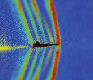
6 116 A. Arabyan and Y. Jiang / A consistent dynamic finite element formulation for a pipe (a) (b) (c) (d) Fig. 6. Motion of flexible pipe for τ = s: (a) τ = 0.07 s; (b) τ = 0.10 s; (c) τ = 0.12 s; (d) τ = 0.15 s. (a) (b) (c) (d) Fig. 7. Motion of flexible pipe for τ = s: (a) τ = 0.17 s; (b) τ = 0.20 s; (c) τ = 0.22 s; (d) τ = 0.24 s.
7 A. Arabyan and Y. Jiang / A consistent dynamic finite element formulation for a pipe 117 The time step size was set to and the relative error tolerance was set to The deformation of the pipe at several points in time are shown in Fig Fast rotating pipes with end lateral force The second example is a pipe rotating about a fixed horizontal axis passing through one end as illustrated in Fig. 5. The pipe has the following properties: E = N/m 2, ν = 0.3, ρ = kg/m 2, L = 3m, R = 0.05 m, and h = 0.01 m. In this simulation, 15 elements were used. Around the pipe cross section two Fourier terms were included for ovalization and warping deformations. This pipe was subjected to a time varying moment at one end, and a lateral force was applied at the other end (see Fig. 5). The moment was increased linearly with time beginning with zero and reaching a final value of 376 N m at τ = s. The final lateral force was 2 N (linearly increasing). The time step size is set to second and the relative error tolerance was set to The deformation at several points in time are shown in Figs 6 7. For a better view of the deformation, the radius of the pipe was magnified by a factor in Figs 6 7. The computation time this simulation was approximately 3 hours on a Sun Sparc Station Concluding remarks The pipe element described by Jiang and Arabyan [5] and this paper exhibits properties that may be very advantageous in the analysis of pipe like structures that undergo large and fast rotations and large deformations. Example of such structure range from umbilical cords used by astronautics and undersea divers to blood vessels in biosystems. The principal feature of the new element is its ability to capture both rigid-body and constant-strain modes. This feature enables the element to be used in circumstances of combined bending, torsional and pressure loads, and large deformations including large crosssectional ovalization and warping. This is a capability that other pipe elements (Bathe and Almeida [3], Ohtsubo [6], and ABAQUS theory manual [1]) do not have. In addition, the new element is substantially more cost efficient computationally than other elements because a pipe-like structure can be modeled with few elements. This advantage was demonstrated earlier in Jiang and Arabyan [5]. In its present form the new element cannot model large strains (by virtue of the strain definition and the total Lagrangian formulation used). The element can be easily modified to model large strains by replacing the strain definitions and the constitutive laws with the appropriate relationships. Such modifications would also have a significant impact on Eqs (13) and (14) and make the dynamic formulation substantially more complex, but remove the thin-shell restriction. Acknowledgements This work is partially supported by the National Science Foundation, Grant Number ECS References [1] ABAQUS Theory Manual, Hibbitt, Karlsson Sorensen, Inc., Version 5.2, [2] K.J. Bathe, Finite Element Procedures in Engineering Analysis, Prentice-Hall, Englewood Cliffs, NJ, [3] K.J. Bathe and C.A. Almeida, A simple and effective pipe elbow element-linear analysis, ASME J. Appl. Mech. 47 (1980), [4] R.D. Cook, D.S. Malkus and M.E. Plesha, Concepts and Applications of Finite Element Analysis, 3rd edn, Wiley, [5] Y. Jiang and A. Arabyan, The development of a new pipe element, Finite Elements in Analysis and Design 22 (1996), [6] H. Ohtsubo and O. Watanabe, Stress analysis of pipe bends by ring elements, J. Pressure Vessel Technol. Trans. ASME 100 (1978),


8 Rotating Machinery Engineering The Scientific World Journal Distributed Sensor Networks Sensors Control Science and Engineering Advances in Civil Engineering Submit your manuscripts at Electrical and Computer Engineering Robotics VLSI Design Advances in OptoElectronics Navigation and Observation Chemical Engineering Active and Passive Electronic Components Antennas and Propagation Aerospace Engineering Volume 2010 Modelling & Simulation in Engineering Shock and Vibration Advances in Acoustics and Vibration
Vibration analysis of circular arch element using curvature
 Shock and Vibration 15 (28) 481 492 481 IOS Press Vibration analysis of circular arch element using curvature H. Saffari a,. Tabatabaei a, and S.H. Mansouri b a Civil Engineering Department, University
Design and control of nonlinear mechanical systems for minimum time
 Shock and Vibration 15 (2008) 315 323 315 IOS Press Design and control of nonlinear mechanical systems for minimum time J.B. Cardoso a,, P.P. Moita b and A.J. Valido b a Instituto Superior Técnico, Departamento
Deflections and Strains in Cracked Shafts due to Rotating Loads: A Numerical and Experimental Analysis
 Rotating Machinery, 10(4): 283 291, 2004 Copyright c Taylor & Francis Inc. ISSN: 1023-621X print / 1542-3034 online DOI: 10.1080/10236210490447728 Deflections and Strains in Cracked Shafts due to Rotating
Mechanics of Inflatable Fabric Beams
 Copyright c 2008 ICCES ICCES, vol.5, no.2, pp.93-98 Mechanics of Inflatable Fabric Beams C. Wielgosz 1,J.C.Thomas 1,A.LeVan 1 Summary In this paper we present a summary of the behaviour of inflatable fabric
Fractal two-level finite element method for free vibration of cracked beams
 61 Fractal two-level finite element method for free vibration of cracked beams A.Y.T. Leung School of Engineering, University of Manchester, Manchester M13 9PL, UK R.K.L. Su Ove Arup & Partners, Hong Kong
Structural Dynamics Lecture 4. Outline of Lecture 4. Multi-Degree-of-Freedom Systems. Formulation of Equations of Motions. Undamped Eigenvibrations.
 Outline of Multi-Degree-of-Freedom Systems Formulation of Equations of Motions. Newton s 2 nd Law Applied to Free Masses. D Alembert s Principle. Basic Equations of Motion for Forced Vibrations of Linear
Structural Dynamics Lecture Eleven: Dynamic Response of MDOF Systems: (Chapter 11) By: H. Ahmadian
 By: H. Ahmadian") Structural Dynamics Lecture Eleven: Dynamic Response of MDOF Systems: (Chapter 11) By: H. Ahmadian ahmadian@iust.ac.ir Dynamic Response of MDOF Systems: Mode-Superposition Method Mode-Superposition Method:
Structural Dynamics Lecture Eleven: Dynamic Response of MDOF Systems: (Chapter 11) By: H. Ahmadian ahmadian@iust.ac.ir Dynamic Response of MDOF Systems: Mode-Superposition Method Mode-Superposition Method:
Dynamic Response Of Laminated Composite Shells Subjected To Impulsive Loads
 IOSR Journal of Mechanical and Civil Engineering (IOSR-JMCE) e-issn: 2278-1684,p-ISSN: 2320-334X, Volume 14, Issue 3 Ver. I (May. - June. 2017), PP 108-123 www.iosrjournals.org Dynamic Response Of Laminated
UNCONVENTIONAL FINITE ELEMENT MODELS FOR NONLINEAR ANALYSIS OF BEAMS AND PLATES
 UNCONVENTIONAL FINITE ELEMENT MODELS FOR NONLINEAR ANALYSIS OF BEAMS AND PLATES A Thesis by WOORAM KIM Submitted to the Office of Graduate Studies of Texas A&M University in partial fulfillment of the
Chapter 3. Load and Stress Analysis
 Chapter 3 Load and Stress Analysis 2 Shear Force and Bending Moments in Beams Internal shear force V & bending moment M must ensure equilibrium Fig. 3 2 Sign Conventions for Bending and Shear Fig. 3 3
VIBRATION PROBLEMS IN ENGINEERING
 VIBRATION PROBLEMS IN ENGINEERING FIFTH EDITION W. WEAVER, JR. Professor Emeritus of Structural Engineering The Late S. P. TIMOSHENKO Professor Emeritus of Engineering Mechanics The Late D. H. YOUNG Professor
Gyroscopic matrixes of the straight beams and the discs
 Titre : Matrice gyroscopique des poutres droites et des di[...] Date : 29/05/2013 Page : 1/12 Gyroscopic matrixes of the straight beams and the discs Summarized: This document presents the formulation
FINITE GRID SOLUTION FOR NON-RECTANGULAR PLATES
 th International Conference on Earthquake Geotechnical Engineering June 5-8, 7 Paper No. 11 FINITE GRID SOLUTION FOR NON-RECTANGULAR PLATES A.Halim KARAŞĐN 1, Polat GÜLKAN ABSTRACT Plates on elastic foundations
Using the finite element method of structural analysis, determine displacements at nodes 1 and 2.
 Question 1 A pin-jointed plane frame, shown in Figure Q1, is fixed to rigid supports at nodes and 4 to prevent their nodal displacements. The frame is loaded at nodes 1 and by a horizontal and a vertical
Mechanical Engineering Ph.D. Preliminary Qualifying Examination Solid Mechanics February 25, 2002
 student personal identification (ID) number on each sheet. Do not write your name on any sheet. #1. A homogeneous, isotropic, linear elastic bar has rectangular cross sectional area A, modulus of elasticity
CO-ROTATIONAL DYNAMIC FORMULATION FOR 2D BEAMS
 COMPDYN 011 ECCOMAS Thematic Conference on Computational Methods in Structural Dynamics and Earthquake Engineering M. Papadrakakis, M. Fragiadakis, V. Plevris (eds.) Corfu, Greece, 5-8 May 011 CO-ROTATIONAL
Buckling Analysis of Ring-Stiffened Laminated Composite Cylindrical Shells by Fourier-Expansion Based Differential Quadrature Method
 Applied Mechanics and Materials Vol. 225 (2012) pp 207-212 (2012) Trans Tech Publications, Switzerland doi:10.4028/www.scientific.net/amm.225.207 Buckling Analysis of Ring-Stiffened Laminated Composite
CIVL 8/7117 Chapter 12 - Structural Dynamics 1/75. To discuss the dynamics of a single-degree-of freedom springmass
 CIV 8/77 Chapter - /75 Introduction To discuss the dynamics of a single-degree-of freedom springmass system. To derive the finite element equations for the time-dependent stress analysis of the one-dimensional
A NOTE ON RELATIONSHIP BETWEEN FIXED-POLE AND MOVING-POLE APPROACHES IN STATIC AND DYNAMIC ANALYSIS OF NON-LINEAR SPATIAL BEAM STRUCTURES
 European Congress on Computational Methods in Applied Sciences and Engineering (ECCOMAS 212) J. Eberhardsteiner et.al. (eds.) Vienna, Austria, September 1-14, 212 A NOTE ON RELATIONSHIP BETWEEN FIXED-POLE
BENCHMARK LINEAR FINITE ELEMENT ANALYSIS OF LATERALLY LOADED SINGLE PILE USING OPENSEES & COMPARISON WITH ANALYTICAL SOLUTION
 BENCHMARK LINEAR FINITE ELEMENT ANALYSIS OF LATERALLY LOADED SINGLE PILE USING OPENSEES & COMPARISON WITH ANALYTICAL SOLUTION Ahmed Elgamal and Jinchi Lu October 07 Introduction In this study: I) The response
D : SOLID MECHANICS. Q. 1 Q. 9 carry one mark each.
 GTE 2016 Q. 1 Q. 9 carry one mark each. D : SOLID MECHNICS Q.1 single degree of freedom vibrating system has mass of 5 kg, stiffness of 500 N/m and damping coefficient of 100 N-s/m. To make the system
Dynamic Model of a Badminton Stroke
 ISEA 28 CONFERENCE Dynamic Model of a Badminton Stroke M. Kwan* and J. Rasmussen Department of Mechanical Engineering, Aalborg University, 922 Aalborg East, Denmark Phone: +45 994 9317 / Fax: +45 9815
COPYRIGHTED MATERIAL. Index
 Index A Admissible function, 163 Amplification factor, 36 Amplitude, 1, 22 Amplitude-modulated carrier, 630 Amplitude ratio, 36 Antinodes, 612 Approximate analytical methods, 647 Assumed modes method,
Dynamic and buckling analysis of FRP portal frames using a locking-free finite element
 Fourth International Conference on FRP Composites in Civil Engineering (CICE8) 22-24July 8, Zurich, Switzerland Dynamic and buckling analysis of FRP portal frames using a locking-free finite element F.
Analytical Strip Method for Thin Isotropic Cylindrical Shells
 IOSR Journal of Mechanical and Civil Engineering (IOSR-JMCE) e-issn: 2278-1684,p-ISSN: 2320-334X, Volume 14, Issue 4 Ver. III (Jul. Aug. 2017), PP 24-38 www.iosrjournals.org Analytical Strip Method for
Chapter 2: Rigid Bar Supported by Two Buckled Struts under Axial, Harmonic, Displacement Excitation..14
 Table of Contents Chapter 1: Research Objectives and Literature Review..1 1.1 Introduction...1 1.2 Literature Review......3 1.2.1 Describing Vibration......3 1.2.2 Vibration Isolation.....6 1.2.2.1 Overview.
Analysis of thin plate structures using the absolute nodal coordinate formulation
 345 Analysis of thin plate structures using the absolute nodal coordinate formulation K Dufva 1 and A A Shabana 2 1 Department of Mechanical Engineering, Lappeenranta University of echnology, Lappeenranta,
The CR Formulation: BE Plane Beam
 6 The CR Formulation: BE Plane Beam 6 Chapter 6: THE CR FORMUATION: BE PANE BEAM TABE OF CONTENTS Page 6. Introduction..................... 6 4 6.2 CR Beam Kinematics................. 6 4 6.2. Coordinate
DETERMINATION OF STRESS INTENSITY FACTORS ALONG CRACKED SURFACES IN PIPING ELBOWS STRUCTURES E.M.M.FONSECA*, F.Q.MELO**, R.A.F.
 1 th PORTUGUESE CONFERENCE ON FRACTURE - 6 DETERMINATION OF STRESS INTENSITY FACTORS ALONG CRACKED SURFACES IN PIPING ELBOWS STRUCTURES E.M.M.FONSECA*, F.Q.MELO**, R.A.F.VALENTE** *CENUME IDMEC Instituto
GEOMETRIC NONLINEAR ANALYSIS
 GEOMETRIC NONLINEAR ANALYSIS The approach for solving problems with geometric nonlinearity is presented. The ESAComp solution relies on Elmer open-source computational tool [1] for multiphysics problems.
On Nonlinear Buckling and Collapse Analysis using Riks Method
 Visit the SIMULIA Resource Center for more customer examples. On Nonlinear Buckling and Collapse Analysis using Riks Method Mingxin Zhao, Ph.D. UOP, A Honeywell Company, 50 East Algonquin Road, Des Plaines,
Consider an elastic spring as shown in the Fig.2.4. When the spring is slowly
 .3 Strain Energy Consider an elastic spring as shown in the Fig..4. When the spring is slowly pulled, it deflects by a small amount u 1. When the load is removed from the spring, it goes back to the original
Modelling and Finite Element Analysis of Double Wishbone Suspension
 Modelling and Finite Element Analysis of Double Wishbone Suspension Amol Patil, Varsha Patil, Prashant Uhle P.G. Student, Dept. of Mechanical Engineering, S S B T S College of Engineering, Jalgaon, Maharastra,
Model tests and FE-modelling of dynamic soil-structure interaction
 Shock and Vibration 19 (2012) 1061 1069 1061 DOI 10.3233/SAV-2012-0712 IOS Press Model tests and FE-modelling of dynamic soil-structure interaction N. Kodama a, * and K. Komiya b a Waseda Institute for
MATHEMATICAL ANALYSIS OF FLY FISHING ROD STATIC AND DYNAMIC RESPONSE
 MATHEMATICAL ANALYSIS OF FLY FISHING ROD STATIC AND DYNAMIC RESPONSE DER-CHEN CHANG, GANG WANG, AND NORMAN M. WERELEY We develop two mathematical models to study the fly fishing rod static and dynamic
ME751 Advanced Computational Multibody Dynamics
 ME751 Advanced Computational Multibody Dynamics November 2, 2016 Antonio Recuero University of Wisconsin-Madison Quotes of the Day The methods which I set forth do not require either constructions or geometrical
Chapter 5 Structural Elements: The truss & beam elements
 Institute of Structural Engineering Page 1 Chapter 5 Structural Elements: The truss & beam elements Institute of Structural Engineering Page 2 Chapter Goals Learn how to formulate the Finite Element Equations
Stress analysis of a stepped bar
 Stress analysis of a stepped bar Problem Find the stresses induced in the axially loaded stepped bar shown in Figure. The bar has cross-sectional areas of A ) and A ) over the lengths l ) and l ), respectively.
Mechanics of Materials II. Chapter III. A review of the fundamental formulation of stress, strain, and deflection
 Mechanics of Materials II Chapter III A review of the fundamental formulation of stress, strain, and deflection Outline Introduction Assumtions and limitations Axial loading Torsion of circular shafts
Outline. Structural Matrices. Giacomo Boffi. Introductory Remarks. Structural Matrices. Evaluation of Structural Matrices
 Outline in MDOF Systems Dipartimento di Ingegneria Civile e Ambientale, Politecnico di Milano May 8, 014 Additional Today we will study the properties of structural matrices, that is the operators that
Introduction to Continuous Systems. Continuous Systems. Strings, Torsional Rods and Beams.
 Outline of Continuous Systems. Introduction to Continuous Systems. Continuous Systems. Strings, Torsional Rods and Beams. Vibrations of Flexible Strings. Torsional Vibration of Rods. Bernoulli-Euler Beams.
Module 3 : Equilibrium of rods and plates Lecture 15 : Torsion of rods. The Lecture Contains: Torsion of Rods. Torsional Energy
 The Lecture Contains: Torsion of Rods Torsional Energy This lecture is adopted from the following book 1. Theory of Elasticity, 3 rd edition by Landau and Lifshitz. Course of Theoretical Physics, vol-7
D : SOLID MECHANICS. Q. 1 Q. 9 carry one mark each. Q.1 Find the force (in kn) in the member BH of the truss shown.
 in the member BH of the truss shown.") D : SOLID MECHANICS Q. 1 Q. 9 carry one mark each. Q.1 Find the force (in kn) in the member BH of the truss shown. Q.2 Consider the forces of magnitude F acting on the sides of the regular hexagon having
D : SOLID MECHANICS Q. 1 Q. 9 carry one mark each. Q.1 Find the force (in kn) in the member BH of the truss shown. Q.2 Consider the forces of magnitude F acting on the sides of the regular hexagon having
Unit 15 Shearing and Torsion (and Bending) of Shell Beams
 of Shell Beams") Unit 15 Shearing and Torsion (and Bending) of Shell Beams Readings: Rivello Ch. 9, section 8.7 (again), section 7.6 T & G 126, 127 Paul A. Lagace, Ph.D. Professor of Aeronautics & Astronautics and Engineering
Unit 15 Shearing and Torsion (and Bending) of Shell Beams Readings: Rivello Ch. 9, section 8.7 (again), section 7.6 T & G 126, 127 Paul A. Lagace, Ph.D. Professor of Aeronautics & Astronautics and Engineering
Horizontal bulk material pressure in silo subjected to impulsive load
 Shock and Vibration 5 (28) 543 55 543 IOS Press Horizontal bulk material pressure in silo subjected to impulsive load Radosław Tatko a, and Sylwester Kobielak b a The Faculty of Environmental Engineering
. D CR Nomenclature D 1
 . D CR Nomenclature D 1 Appendix D: CR NOMENCLATURE D 2 The notation used by different investigators working in CR formulations has not coalesced, since the topic is in flux. This Appendix identifies the
CHAPTER THREE SYMMETRIC BENDING OF CIRCLE PLATES
 CHAPTER THREE SYMMETRIC BENDING OF CIRCLE PLATES * Governing equations in beam and plate bending ** Solution by superposition 1.1 From Beam Bending to Plate Bending 1.2 Governing Equations For Symmetric
1 Nonlinear deformation
 NONLINEAR TRUSS 1 Nonlinear deformation When deformation and/or rotation of the truss are large, various strains and stresses can be defined and related by material laws. The material behavior can be expected
NUMERICAL SIMULATION OF STEEL CATENARY RISER
 SIMMEC/EMMCOMP 214 XI Simpósio de Mecânica Computacional II Encontro Mineiro de Modelagem Computacional Juiz De Fora, MG, 28-3 de Maio De 214 NUMERICAL SIMULATION OF STEEL CATENARY RISER Marcus V. S. Casagrande
Lecture 7: The Beam Element Equations.
 4.1 Beam Stiffness. A Beam: A long slender structural component generally subjected to transverse loading that produces significant bending effects as opposed to twisting or axial effects. MECH 40: Finite
CE 715: Advanced Strength of Materials
 CE 715: Advanced Strength of Materials Lecture 1 CE 715 Course Information Instructor: Tasnim Hassan Office: Mann Hall 419 Office Hours: TTh 2:00-4:00 pm Phone: 515-8123 Email: thassan@eos.ncsu.edu 1 Course
Chapter 2 Finite Element Formulations
 Chapter 2 Finite Element Formulations The governing equations for problems solved by the finite element method are typically formulated by partial differential equations in their original form. These are
Numerical simulation of the coil spring and investigation the impact of tension and compression to the spring natural frequencies
 Numerical simulation of the coil spring and investigation the impact of tension and compression to the spring natural frequencies F. D. Sorokin 1, Zhou Su 2 Bauman Moscow State Technical University, Moscow,
Nonlinear analysis in ADINA Structures
 Nonlinear analysis in ADINA Structures Theodore Sussman, Ph.D. ADINA R&D, Inc, 2016 1 Topics presented Types of nonlinearities Materially nonlinear only Geometrically nonlinear analysis Deformation-dependent
Chapter 5 Elastic Strain, Deflection, and Stability 1. Elastic Stress-Strain Relationship
 Chapter 5 Elastic Strain, Deflection, and Stability Elastic Stress-Strain Relationship A stress in the x-direction causes a strain in the x-direction by σ x also causes a strain in the y-direction & z-direction
University of Groningen
 University of Groningen Nature-inspired microfluidic propulsion using magnetic actuation Khaderi, S. N.; Baltussen, M. G. H. M.; Anderson, P. D.; Ioan, D.; den Toonder, J.M.J.; Onck, Patrick Published
Review of Strain Energy Methods and Introduction to Stiffness Matrix Methods of Structural Analysis
 uke University epartment of Civil and Environmental Engineering CEE 42L. Matrix Structural Analysis Henri P. Gavin Fall, 22 Review of Strain Energy Methods and Introduction to Stiffness Matrix Methods
Structural Matrices in MDOF Systems
 in MDOF Systems http://intranet.dica.polimi.it/people/boffi-giacomo Dipartimento di Ingegneria Civile Ambientale e Territoriale Politecnico di Milano April 9, 2016 Outline Additional Static Condensation
Table of Contents. Preface... 13
 Table of Contents Preface... 13 Chapter 1. Vibrations of Continuous Elastic Solid Media... 17 1.1. Objective of the chapter... 17 1.2. Equations of motion and boundary conditions of continuous media...
Codal Provisions IS 1893 (Part 1) 2002
 2002") Abstract Codal Provisions IS 1893 (Part 1) 00 Paresh V. Patel Assistant Professor, Civil Engineering Department, Nirma Institute of Technology, Ahmedabad 38481 In this article codal provisions of IS 1893
Abstract Codal Provisions IS 1893 (Part 1) 00 Paresh V. Patel Assistant Professor, Civil Engineering Department, Nirma Institute of Technology, Ahmedabad 38481 In this article codal provisions of IS 1893
Geometry-dependent MITC method for a 2-node iso-beam element
 Structural Engineering and Mechanics, Vol. 9, No. (8) 3-3 Geometry-dependent MITC method for a -node iso-beam element Phill-Seung Lee Samsung Heavy Industries, Seocho, Seoul 37-857, Korea Hyu-Chun Noh
Beam Models. Wenbin Yu Utah State University, Logan, Utah April 13, 2012
 Beam Models Wenbin Yu Utah State University, Logan, Utah 843-4130 April 13, 01 1 Introduction If a structure has one of its dimensions much larger than the other two, such as slender wings, rotor blades,
Methods of Analysis. Force or Flexibility Method
 INTRODUCTION: The structural analysis is a mathematical process by which the response of a structure to specified loads is determined. This response is measured by determining the internal forces or stresses
Geometric nonlinear formulation for curved beams with varying curvature
 THEORETICAL & APPLIED MECHANICS LETTERS 2, 636 212) Geometric nonlinear formulation for curved beams with varying curvature Keqi Pan, a) and Jinyang Liu b) School of Naval Architecture, Ocean and Civil
7. Hierarchical modeling examples
 7. Hierarchical modeling examples The objective of this chapter is to apply the hierarchical modeling approach discussed in Chapter 1 to three selected problems using the mathematical models studied in
Lecture 15 Strain and stress in beams
 Spring, 2019 ME 323 Mechanics of Materials Lecture 15 Strain and stress in beams Reading assignment: 6.1 6.2 News: Instructor: Prof. Marcial Gonzalez Last modified: 1/6/19 9:42:38 PM Beam theory (@ ME
Study of coupling between bending and torsional vibration of cracked rotor system supported by radial active magnetic bearings
 Applied and Computational Mechanics 1 (2007) 427-436 Study of coupling between bending and torsional vibration of cracked rotor system supported by radial active magnetic bearings P. Ferfecki a, * a Center
Example 3.7 Consider the undeformed configuration of a solid as shown in Figure 3.60.
 162 3. The linear 3-D elasticity mathematical model The 3-D elasticity model is of great importance, since it is our highest order hierarchical model assuming linear elastic behavior. Therefore, it provides
Introduction to Aerospace Engineering
 Introduction to Aerospace Engineering Lecture slides Challenge the future 1 Aircraft & spacecraft loads Translating loads to stresses Faculty of Aerospace Engineering 29-11-2011 Delft University of Technology
New implicit method for analysis of problems in nonlinear structural dynamics
 Applied and Computational Mechanics 5 (2011) 15 20 New implicit method for analysis of problems in nonlinear structural dynamics A. A. Gholampour a,, M. Ghassemieh a a School of Civil Engineering, University
Correspondence should be addressed to Kuo Mo Hsiao,
 Mathematical Problems in Engineering Volume 2, Article ID 4655, 29 pages doi:.55/2/4655 Research Article A Corotational Finite Element Method Combined with Floating Frame Method for Large Steady-State
NONLINEAR CONTINUUM FORMULATIONS CONTENTS
 NONLINEAR CONTINUUM FORMULATIONS CONTENTS Introduction to nonlinear continuum mechanics Descriptions of motion Measures of stresses and strains Updated and Total Lagrangian formulations Continuum shell
CRITERIA FOR SELECTION OF FEM MODELS.
 CRITERIA FOR SELECTION OF FEM MODELS. Prof. P. C.Vasani,Applied Mechanics Department, L. D. College of Engineering,Ahmedabad- 380015 Ph.(079) 7486320 [R] E-mail:pcv-im@eth.net 1. Criteria for Convergence.
Large Amplitude Vibrations and Modal Sensing of Intelligent Thin Piezolaminated Structures
 Large Amplitude Vibrations and Modal Sensing of Intelligent Thin Piezolaminated Structures S. Lentzen and R. Schmidt Insitut of General Mechanics, RWTH Aachen University Contents MRT FOSD theory of shells
Presented By: EAS 6939 Aerospace Structural Composites
 A Beam Theory for Laminated Composites and Application to Torsion Problems Dr. BhavaniV. Sankar Presented By: Sameer Luthra EAS 6939 Aerospace Structural Composites 1 Introduction Composite beams have
Finite Element Analysis Prof. Dr. B. N. Rao Department of Civil Engineering Indian Institute of Technology, Madras. Module - 01 Lecture - 13
 Finite Element Analysis Prof. Dr. B. N. Rao Department of Civil Engineering Indian Institute of Technology, Madras (Refer Slide Time: 00:25) Module - 01 Lecture - 13 In the last class, we have seen how
Mechanical Design in Optical Engineering
 Torsion Torsion: Torsion refers to the twisting of a structural member that is loaded by couples (torque) that produce rotation about the member s longitudinal axis. In other words, the member is loaded
Verification Examples. FEM-Design. version
 FEM-Design 6.0 FEM-Design version. 06 FEM-Design 6.0 StruSoft AB Visit the StruSoft website for company and FEM-Design information at www.strusoft.com Copyright 06 by StruSoft, all rights reserved. Trademarks
3-D FINITE ELEMENT NONLINEAR DYNAMIC ANALYSIS FOR SOIL-PILE-STRUCTURE INTERACTION
 13 th World Conference on Earthquake Engineering Vancouver, B.C., Canada August 1-, 4 Paper No. 157 3-D FINITE ELEMENT NONLINEAR DYNAMIC ANALYSIS FOR SOIL-PILE-STRUCTURE INTERACTION B.K. MAHESHWARI 1,
Finite Element Method in Geotechnical Engineering
 Finite Element Method in Geotechnical Engineering Short Course on + Dynamics Boulder, Colorado January 5-8, 2004 Stein Sture Professor of Civil Engineering University of Colorado at Boulder Contents Steps
Lecture Pure Twist
 Lecture 4-2003 Pure Twist pure twist around center of rotation D => neither axial (σ) nor bending forces (Mx, My) act on section; as previously, D is fixed, but (for now) arbitrary point. as before: a)
JEPPIAAR ENGINEERING COLLEGE
 JEPPIAAR ENGINEERING COLLEGE Jeppiaar Nagar, Rajiv Gandhi Salai 600 119 DEPARTMENT OFMECHANICAL ENGINEERING QUESTION BANK VI SEMESTER ME6603 FINITE ELEMENT ANALYSIS Regulation 013 SUBJECT YEAR /SEM: III
BAR ELEMENT WITH VARIATION OF CROSS-SECTION FOR GEOMETRIC NON-LINEAR ANALYSIS
 Journal of Computational and Applied Mechanics, Vol.., No. 1., (2005), pp. 83 94 BAR ELEMENT WITH VARIATION OF CROSS-SECTION FOR GEOMETRIC NON-LINEAR ANALYSIS Vladimír Kutiš and Justín Murín Department
Bending of Simply Supported Isotropic and Composite Laminate Plates
 Bending of Simply Supported Isotropic and Composite Laminate Plates Ernesto Gutierrez-Miravete 1 Isotropic Plates Consider simply a supported rectangular plate of isotropic material (length a, width b,
Strength of Materials Prof S. K. Bhattacharya Department of Civil Engineering Indian Institute of Technology, Kharagpur Lecture - 18 Torsion - I
 Strength of Materials Prof S. K. Bhattacharya Department of Civil Engineering Indian Institute of Technology, Kharagpur Lecture - 18 Torsion - I Welcome to the first lesson of Module 4 which is on Torsion
Large Thermal Deflections of a Simple Supported Beam with Temperature-Dependent Physical Properties
 Large Thermal Deflections of a Simple Supported Beam with Temperature-Dependent Physical Properties DR. ŞEREF DOĞUŞCAN AKBAŞ Civil Engineer, Şehit Muhtar Mah. Öğüt Sok. No:2/37, 34435 Beyoğlu- Istanbul,
Hand Calculations of Rubber Bearing Seismic Izolation System for Irregular Buildings in Plane
 Hand Calculations of Rubber Bearing Seismic Izolation System for Irregular Buildings in Plane Luan MURTAJ 1, Enkelejda MURTAJ 1 Pedagogue, Department of Structural Mechanics Faculty of Civil Engineering
A Multi-nodal Ring Finite Element for Analysis of Pipe Deflection
 A Multi-nodal Ring Finite Element for Analysis of Pipe Deflection 109 A Multi-nodal Ring Finite Element for Analysis of Pipe Deflection E.M.M. Fonseca 1, F.J.M.Q. de Melo and M.L.R. Madureira 3 1 Department
Basic Equations of Elasticity
 A Basic Equations of Elasticity A.1 STRESS The state of stress at any point in a loaded bo is defined completely in terms of the nine components of stress: σ xx,σ yy,σ zz,σ xy,σ yx,σ yz,σ zy,σ zx,andσ
MITOCW MITRES2_002S10linear_lec07_300k-mp4
 MITOCW MITRES2_002S10linear_lec07_300k-mp4 The following content is provided under a Creative Commons license. Your support will help MIT OpenCourseWare continue to offer high quality educational resources
Aeroelastic effects of large blade deflections for wind turbines
 Aeroelastic effects of large blade deflections for wind turbines Torben J. Larsen Anders M. Hansen Risoe, National Laboratory Risoe, National Laboratory P.O. Box 49, 4 Roskilde, Denmark P.O. Box 49, 4
Virtual distortions applied to structural modelling and sensitivity analysis. Damage identification testing example
 AMAS Workshop on Smart Materials and Structures SMART 03 (pp.313 324) Jadwisin, September 2-5, 2003 Virtual distortions applied to structural modelling and sensitivity analysis. Damage identification testing
ON EFFECTIVE IMPLICIT TIME INTEGRATION IN ANALYSIS OF FLUID-STRUCTURE PROBLEMS
 SHORT COMMUNICATIONS 943 ON EFFECTIVE IMPLICIT TIME INTEGRATION IN ANALYSIS OF FLUID-STRUCTURE PROBLEMS KLAUS-JURGEN BATHE? AND VUAY SONNADS Dcpaflment of Mechanical Engineering, Massachusetts Institute
Degenerated shell element for geometrically nonlinear analysis of thin-walled piezoelectric active structures
 IOP PUBLISHING Smart Mater. Struct. 17 (2008) 015030 (10pp) SMART MATERIALS AND STRUCTURES doi:10.1088/0964-1726/17/01/015030 Degenerated shell element for geometrically nonlinear analysis of thin-walled
Static & Dynamic. Analysis of Structures. Edward L.Wilson. University of California, Berkeley. Fourth Edition. Professor Emeritus of Civil Engineering
 Static & Dynamic Analysis of Structures A Physical Approach With Emphasis on Earthquake Engineering Edward LWilson Professor Emeritus of Civil Engineering University of California, Berkeley Fourth Edition
M.S Comprehensive Examination Analysis
 UNIVERSITY OF CALIFORNIA, BERKELEY Spring Semester 2014 Dept. of Civil and Environmental Engineering Structural Engineering, Mechanics and Materials Name:......................................... M.S Comprehensive
Part D: Frames and Plates
 Part D: Frames and Plates Plane Frames and Thin Plates A Beam with General Boundary Conditions The Stiffness Method Thin Plates Initial Imperfections The Ritz and Finite Element Approaches A Beam with
3. BEAMS: STRAIN, STRESS, DEFLECTIONS
 3. BEAMS: STRAIN, STRESS, DEFLECTIONS The beam, or flexural member, is frequently encountered in structures and machines, and its elementary stress analysis constitutes one of the more interesting facets
4. SHAFTS. A shaft is an element used to transmit power and torque, and it can support
 4. SHAFTS A shaft is an element used to transmit power and torque, and it can support reverse bending (fatigue). Most shafts have circular cross sections, either solid or tubular. The difference between
Dispersion relation for transverse waves in a linear chain of particles
 Dispersion relation for transverse waves in a linear chain of particles V. I. Repchenkov* It is difficult to overestimate the importance that have for the development of science the simplest physical and