University Politehnica Timisoara The Faculty of Electrical and Power Engineering. Habilitation Thesis Teza de abilitare
|
|
|
- Deirdre Wheeler
- 6 years ago
- Views:
Transcription

1 University Politehnica Timisoara The Faculty of Electrical and Power Engineering Teza de abilitare Intelligent monitoring systems achievement applied in power systems Doru VĂTĂU Associate professor, PhD. Reg. no. M.E.N. 2014
2 CONTENTS 1. Abstract Abstract Rezumat Technical Presentation Overview of Activity and Results, Systems for monitoring and analysis of the technical status of the materials, electrical machines and electrical equipment used in power systems Power quality monitoring equipment designed for the connection points between the transmission and distribution network Power generation, transmission and delivery environment impact monitoring systems Development. Future Works References General References List of Publications List of Grants Selection Annex
3 1. ABSTRACT 1.1. Abstract In the frame of the habilitation thesis are prezented the most important personal achievements on scientific, professional and academical plan that I ve obtained in the period of time January 1997 June This period follows to my public presentation of the PhD thesis that took place on January 17 th, 1997 (later confirmed by the Order of the Ministry of Education No from June 2 nd, 1997). The habilitation thesis is structured in three parts: the abstract, the technical presentation and the bibliographic references. The habilitation thesis starts with an abstract that includes the synthesis of the habilitation thesis typed in English, as well as in Romanian language. The second part of the thesis, named Technical Presentation includes five sections. In the first section are presented briefly the remarkable achievements obtained through research and educational activities (list with publications and grants classified on three research directions, new disciplines introduced in the education plans, taught courses, contributions brought to the development of the syllabus, invited professor, practice activities with students, conducting license and dissertation theses, endowed laboratories and library, international cooperation, management activities, etc.). It has to be mentioned that in the period of time I ve published a number of 87 scientific articles, I ve participated in the frame of 13 research grants / contracts won through competition (at 6 of them I was project director) and I ve elaborated 10 books in the fields connected to the present thesis. The second section presents the contributions adequate to the first research direction Systems for monitoring and analysis of the technical status of the materials, electrical machines and electrical equipment used in power systems. Studies performed in the frame of this research direction were unfurled initially separately on three planes: materials used in electrical and power engineering, electrical apparatus and equipment used in electric power installations, respectively electrical machines. Afterwards, a part of the obtained results were used in conceiving and achieving some products and some monitoring and analysis systems for the assessment of technical conditions inside power systems. The contributions brought in this research direction were published in 7 specialty books and 72 articles, the researches being unfurled in the frame of 8 research grants / contracts, whereas at 2 of them I was director. The first two works presented refer to the results obtained the study of varistors with zinc oxide (the influence of the manufacturing technology used on their qualities, the wear of the varistors based on ZnO during exploitation, a new method for the increase of the heat absorbtion capacity for a varistor based on ZnO etc.). The next paper presents an overvoltage protection module BMS 01 conceived, designed, achieved, tested, homologated and afterwards marketed by the author. At the respective moment, it was the first protection module class D entirely designed and achieved in Romania. The next two contributions presented make reference to the monitoring and analysis systems of the technical conditions of some high voltage electrical equipments. The last contributions presented refer to electrical induction machines and hydrogenerators. The third section makes reference to the contributions obtained in the second research direction Power quality monitoring equipment designed for the connection points between the transmission and distribution network. The contributions brought on this topic were published in 2 specialty books and 6 articles, the researches being unfurled in the frame of 3 research grants / contracts, whereas at 2 of them I was director. It is presented a power quality 3
4 monitoring system, at the voltage level of 110 kv, considering the existing situation at the respective moment. There are presented and commented a series of experimental results for different electric substations in the frame of the Romanian Power Grid Company Transelectrica, Transport Subsidiary Sibiu. The fourth section presents the contributions from the third research direction Power generation, transmission and delivery environment impact monitoring systems. The contributions brought in this research direction were published in a specialty book and 9 articles, the researches being unfurled in the frame of 2 research grants / contracts, where I was director. It is presented an on-line system for the permanent monitoring of the impact on the environment, as well as a series of data registered with this system at different transforming stations in Romania. The registered data are then commented, being presented a series of measures for the protection of people and of the environment that must be considered during the exploitation of the installations. The last section presents the evolution and development plan regarding the professional, scientific and academic career, as well as exact methods of putting them into practice. The conceived action plan includes three directions of research / teaching / practical applications that are: renewable energy sources; materials, equipments, methods and work techniques under high voltage; the impact of electrical installations on the environment. There are proposed a series of actual studies, such as: the study of the behavior of insulation systems to external loads (high temperature and/or high electric fields and/or high magnetic fields); studies of the electrical equipments destined to the work under high voltage (LST); achievement of laboratory tests and epidemiologic analysis for the evaluation of the influence of electric and/or magnetic field on human body; modelling of photovoltaic systems, in the meaning of extracting the maximal possible energy; the integration of fuel cells in different applications, etc. There are presented, as well, some methods for reaching these targets (objectives). The third part of the habilitation thesis is dedicated to the bibliographic references grouped into: general references, list with publications in the period of time and list with grants unfurled in the period of time The habilitation thesis ends with an annex regarding the overvoltage protection module, class D, manufactured by S.C. Protenergo S.A. from Timişoara, company where I was marketing director Rezumat În cadrul tezei de abilitare sunt prezentate cele mai importante realizări personale în plan ştiinţific, profesional şi academic pe care le-am obţinut în perioada ianuarie 1997 iunie Această perioadă urmează susţinerii publice a tezei mele de doctorat, care a avut loc în 17 ianuarie 1997 (confirmată ulterior prin Ordinul ministrului învăţământului nr din 2 iunie 1997). Teza de abilitare este structurată pe trei părţi: rezumatul, prezentarea tehnică şi referinţele bibliografice. Lucrarea debutează cu un rezumat ce cuprinde sinteza tezei de abilitare redactat atât în limba engleză cât şi în limba română. Partea a doua a tezei, denumită Prezentare tehnică cuprinde cinci secţiuni. În prima secţiune sunt prezentate sumar realizările remarcabile obţinute în activitățile de cercetare şi didactică (listă de publicații şi granturi clasificate în trei direcții de cercetare, discipline nou introduse în planurile de învățământ, cursuri predate, contribuții aduse la 4
5 dezvoltarea syllabusurilor, profesor invitat, activități de practică cu studenții, conducerea lucrărilor de licență şi disertație, dotare laboratoare şi bibliotecă, cooperare internațională, activități de management etc.). De menționat că în perioada am publicat un număr de 87 de articole ştiințifice, am participat în cadrul a 13 granturi/contracte de cercetare câştigate prin competiție (la 6 dintre ele fiind director de proiect) şi am elaborat 10 cărți în domenii conexe prezentei teze. A doua secţiune prezintă contribuţiile aferente primei direcţii de cercetare Sisteme de monitorizare şi analiză a stării tehnice a materialelor, maşinilor, aparatelor şi echipamentelor electrice utilizate în instalaţiile electroenergetice. Studiile efectuate în cadrul acestei direcţii de cercetare s-au desfăşurat iniţial separat pe trei planuri: materiale electrotehnice, aparate şi echipamente electrice şi respectiv maşini electrice. Apoi, o parte dintre rezultatele obţinute au fost utilizate în conceperea şi realizarea unor produse şi unor sisteme de monitorizare şi analiză a stării tehnice a activelor din instalaţiile electroenergetice. Contribuţiile aduse în această direcţie de cercetare au fost publicate în 7 cărţi de specialitate şi 72 articole, cercetările derulându-se în cadrul a 8 granturi/contracte de cercetare, la 2 dintre ele fiind director. Primele două lucrări prezentate se referă la rezultatele obţinute în studiul varistoarelor pe bază de oxid de zinc (influenţa tehnologiei de fabricaţie folosite asupra calităţii acestora, uzura varistoarelor pe bază de ZnO în exploatare, o nouă metodă pentru creșterea capacității de absorbție termică pentru un varistor pe bază de ZnO etc.). Următoarea lucrare prezintă un modul de protecţie contra supratensiunilor BMS 01 conceput, proiectat, realizat, încercat, omologat si apoi comercializat pe piaţă de către autor. A fost, la momentul respectiv, primul modul de protecţie clasa D conceput şi realizat integral în România. Următoarele două contribuţii prezentate se referă la sisteme de monitorizare şi analiză a stării tehnice a unor echipamente electrice de înaltă tensiune. Ultimele contribuţii prezentate se referă la maşinile electrice de inducţie şi hidrogeneratoare. Secţiunea a treia se referă la contributiile obţinute în a doua direcţie de cercetare Sisteme de monitorizare a calităţii energiei electrice la interfaţa dintre reţeaua de transport şi cea de distribuţie. Contribuţiile aduse pe această tematică au fost publicate în 2 cărţi de specialitate şi 6 articole, cercetările derulându-se în cadrul a 3 granturi/contracte de cercetare, la 2 dintre ele fiind director. Se prezintă un sistem de monitorizare a calităţii energiei electrice, la nivelul de tensiune 110 kv, avându-se în vedere situaţia existentă la momentul respectiv. Sunt prezentate şi comentate o serie de rezultate experimentale pentru diverse staţii electrice din cadrul Companiei Naţionale de Transport al Energiei Electrice Transelectrica SA., Sucursala de Transport Sibiu. A patra secţiune prezintă contribuţiile din a treia direcţie de cercetare Sisteme de monitorizare a impactului instalaţiilor de producere, transport şi distribuţie a energiei electrice asupra mediului înconjurător. Contribuţiile aduse în această direcţie de cercetare au fost publicate într-o carte de specialitate şi 9 articole, cercetările derulându-se în cadrul a 2 granturi/contracte de cercetare, la ambele fiind director. Se prezintă un sistem on-line de monitorizare permanentă a impactului asupra mediului înconjurător precum şi o serie de date înregistrate cu acest sistem în diverse staţii electrice de transformare din Romania. Datele înregistrate sunt apoi comentate, prezentându-se o serie de măsuri de protecţie a oamenilor şi mediului, care trebuiesc avute în vedere pe parcursul exploatării instalaţiilor. Ultima secţiune prezintă planul de evoluție şi dezvoltare cu privire la cariera profesională, ştiințifică şi academică precum şi modalitățile concrete de punere a acestora în practică. Planul de acţiuni conceput include trei direcţii de cercetare / predare / aplicaţii practice, şi anume: surse de energie regenerabile; materiale, echipamente, metode şi tehnici de lucru sub înaltă tensiune; impactului instalaţiilor electroenergetice asupra mediului înconjurător. Sunt propuse o serie de studii de actualitate precum: studiul comportării sistemelor de izolaţie la solicitări extreme (temperatură înaltă şi/sau câmpuri electrice mari 5
6 şi/sau câmpuri magnetice mari); studii asupra echipamentelor electrice destinate lucrului sub înaltă tensiune (LST); realizarea unor teste de laborator şi anchete epidemiologice în vederea evaluării influenţei câmpului electric şi/sau magnetic asupra organismului uman; modelarea sistemelor electroenergetice solare, în sensul captării unei energii maxime posibile; integrarea pilelor de combustie în diverse aplicaţii etc.. Sunt prezentate, de asemenea, unele modalităţi de atingere a acestor planuri. Partea a treia a tezei de abilitare este dedicată referinţelor bibliografice grupate în: referinţe generale, lista publicaţiilor din perioada şi lista granturilor derulate în intervalul Teza de abilitare se încheie cu o anexă, referitoare la modulul de protecţie contra supratensiunilor, clasa D, produs de către S.C. Protenergo S.A. din Timişoara, firmă la care am fost director de marketig. 2. TECHNICAL PRESENTATION 2.1. Overview of Activity and Results On January 17 th, 1997 I ve asserted publicly the PhD thesis with the title Contributions to the design of the electromagnetic devices for the vehiculation of electric conducting liquids. Applications to the magneto-hydrodynamic repulsion pump. Afterwards, by the Order of the Ministry of Education No from June 2 nd, 1997, I ve obtained the title of Doctor Engineer. The personal achievements in the scientific, professional and academic plane shall be presented below, only for the period of time June During this period of time, as teaching staff of the Politehnica University of Timişoara I ve asserted a series of disciplines, correlated with the local and international standards, that are: Electrical apparatus and equipment (3rd year, Electrical Engineering, Faculty of Electrical and Power Engineering); Electrical energy use and large consumers 3rd year, Power Engineering, Faculty of Electrical and Power Engineering); Materials and technologies (2nd year, Economical Engineering, Faculty of Management in Production and Transport); Solid physics (1st year, Economical Engineering, Faculty of Management in Production and Transport); Materials used in electrical engineering (2th year, Electrical Engineering, Faculty of Electrical and Power Engineering); Materials used in power engineering (2nd year, Power Engineering, Faculty of Electrical and Power Engineering); Environment power facilities impact (3rd year, Power Engineering, Faculty of Electrical and Power Engineering); Power plants, substations and electrical networks (4th year, Electrical Engineering, Faculty of Electrical and Power Engineering); Renewable energy use in industry and buildings (2nd year MsC, Renewable energy engineering and 2nd year MsC, Energy and ecology in thermal and transport vehicles field, Mechanical Faculty); Energy efficient use (postgraduate learning program for the power managers in energy management field, based on the regulations provided by the decision 6
7 no. 58 / elaborated by the Romanian Agency for Energy Conservation published in Official Romanian Monitor, 1st part no. 423 / , regarding the approval of "Guidelines for students' training and testing in energy management field"). The assimilation of the mentioned disciplines, the development of analytic programs and their assertion was possible only by a full correlation between the teaching and research activity. The special results registered in the frame of the research activity were found also in the elaborated teaching materials. The research activity, unfurled in the frame of the University Politehnica Timişoara, as well as at other renamed European universities (University Paul Sabatier of Toulouse, University of Chemical Technology and Metallurgy of Sofia a.o.) and companies (S.C. Protenergo S.A. in Timişoara where I was marketing director in the period of time ), was structured on following research activities: Systems for monitoring and analysis of the technical status of the materials, electrical machines and electrical equipment used in power systems; Power quality monitoring equipment designed for the connection points between the transmission and distribution network; Power generation, transmission and delivery environment impact monitoring systems. In each of these three research directions I ve had important contributions. The contributions regarding the systems for monitoring and analysis of the technical status of the materials, electrical machines and electrical equipment used in power systems are presented in chapter 2.2. In this chapter I ve made reference to a series of results obtained from researches performed in this field, results presented in: 7 specialty books published at publishing companies of the country, recognized by CNCSIS, among them being one typed in French language, [Book99_1], [Book99_2], [Book01_1], [Book03_1], [Book05_1], [Book09_1], [Book12_1]; 9 articles published in the volumes of international scientific manifestations (proceedings), quoted ISI, [ISI07_1], [ISI07_2], [ISI07_4], [ISI08_1], [ISI08_2], [ISI08_3], [ISI09_1], [ISI10_1], [ISI13_1]; 3 articles published in specialty journals, indexed in international data basis (BDI), [BDI06_1], [BDI06_2], [BDI09_1]; 6 articles published in the volumes of some international scientific manifestations (proceedings), indexed in international data basis (BDI), [BDI98_1], [BDI00_1], [BDI10_1], [BDI10_2], [BDI11_2], [BDI11_3]; 3 articles published in other specialty journals abroad, [Paper99_1], [Paper07_1], [Paper07_2]; 9 articles published in the volumes of some scientific manifestations abroad, [Paper00_1], [Paper00_2], [Paper04_1], [Paper04_2], [Paper07_3], [Paper07_4], [Paper07_5], [Paper08_1], [Paper08_2]; 27 articles published in specialty journals in the country, recognized by CNCSIS (category B), [Paper97_1], [Paper97_2], [Paper98_1], [Paper98_2], [Paper98_3], [Paper98_4], [Paper98_5], [Paper98_6], [Paper98_7], [Paper99_2], [Paper99_3], [Paper01_1], [Paper01_2], [Paper01_3], [Paper01_4], [Paper01_5], [Paper01_6], [Paper01_7], [Paper02_1], [Paper02_2], [Paper03_1], [Paper03_2], [Paper05_1], [Paper05_2], [Paper07_6], [Paper07_7], [Paper07_8]; 15 articles published in the volumes of some international scientific manifestations organized in Romania (with scientific referents), [Paper97_3], [Paper98_8], [Paper99_4], [Paper00_3], [Paper00_4], [Paper00_5], 7
8 [Paper00_6], [Paper00_7], [Paper01_8], [Paper01_9], [Paper01_10], [Paper01_11], [Paper01_12], [Paper01_13], [Paper01_14]. A great part of the published results that treat problems specific to materials used in the electrical and power engineering, electrical machines and electrical equipments was obtained as a result of researches performed in the frame of: 4 international research grants won through competition [Grant_01], [Grant_02], [Grant_05], [Grant_06]; a national research grant (CNCSIS) won through competition, [Grant_08]; 3 research contracts / consultancy unfurled on the demand and under the financing of some companies in Romania, [Grant_10], [Grant_11] and [Grant_12]. I mention that, as grant director, I ve coordinated the research activities unfurled in the frame of 3 international research grants that are: o Varistance haut puissance à base d oxyde de zinc, grant unfurled in the frame of the program INCO-COPERNICUS HIPOVAR, [Grant_01]; o Système de formation continue par la recherche dans le domaine de la maintenance des installations électriques, grant unfurled with the financial support of the University Agency of Francofony, [Grant_02]; o Modélisation et caractérisation des propriétés thermiques dans des fluides contenant des nano inclusions anisotropes de forme différente, grant unfurled with the financial support of the University Agency of Francofony, [Grant_05]; The contributions regarding the power quality monitoring equipment designed for the connection points between the transmission and distribution network are presented in chapter 2.3. In chapter 2.3 I ve made reference to one of the results obtained from the researches performed, results that I ve presented afterwards in: 2 specialty books published at publishing companies inside the country, recognized by CNCSIS, among which one was published in French language, [Book04_1] and [Book08_2]; 2 articles published in the volumes of some international scientific manifestations (proceedings), indexed ISI, [ISI09_2] and [ISI09_4]; 4 articles published in the volumes of some international scientific manifestations (proceedings), indexed in international data basis (BDI), [BDI12_1], [BDI12_2], [BDI12_3] and [BDI12_4]. A part of the published results, regarding different problems connected to the power quality was obtained as a result of researches performed in the frame of: 2 international research grants won through competition [Grant_03] and [Grant_04]; a national research grant (CNCSIS) won through competition, [Grant_09]. I mention that, as grant director, I ve coordinated the research activities unfurled in the frame of 2 international research grants that are: o La qualité de l'énergie électrique transferée entre l'europe de l'est et l'europe de L'Ouest, grant unfurled with the financial support of the University Agency of Francofony, [Grant_03]; o Tehimpuls-Brokinnovoucher Support for the cooperation and innovation of small and medium enterprises in the area Romania - Hungaria, Project financed through the Program Phare CBC Romania - Hungaria Regional Center of Innovation and Technological Transfer [Grant_04]; The contributions regarding the power generation, transmission and delivery environment impact monitoring systems are presented in chapter 2.4. In this chapter I ve 8
9 made reference to a series of results obtained from researches performed in this field, results presented in: one specialty book published by a publishing company inside the country, recognized CNCSIS, [Book08_1]; 2 articles published in the volumes of some international scientific manifestations (proceedings), indexed ISI, [ISI07_3] and [ISI09_3]; 7 articles published in the volumes of some international scientific manifestations (proceedings), indexed in international data basis (BDI), [BDI11_1], [BDI11_4], [BDI11_5], [BDI11_6], [BDI12_2], [BDI13_1] and [BDI14_1]; A part of the published results that treat problems regarding the impact of electrical installations on the environment was obtained as a result of researches performed in the frame of: one international research grant won through competition [Grant_03]; one international research contract won through competition, [Grant_13]. I mention that, as grant director, I ve coordinated the research activities unfurled in the frame of 2 international research grants that are: o La qualité de l'énergie électrique transferée entre l'europe de l'est et l'europe de L'Ouest, grant unfurled with the financial support of the University Agency of Francofony, [Grant_03]; o L'impact des installations électriques sur l environnement et Matériaux pour le génie électrique, contract unfurled with the financial support of the University Agency of Francofony, [Grant_13]. I mention, as well, that I ve finished the entire material needed for being published in a new specialty book entitled Impact of electrical installations on the environment. The work shall be published in the frame of the year 2014 and shall be useful for each studend and engineer that is active in the electrical and energy field. In the period of time , by filling in the things mentioned above, I ve unfurled a series of other teaching and scientific activities, such as: I ve contributed to the development of the material base in accordance with the specific standards of the laboratories of Electrical apparatus and equipment and Electrotechnic materials, by: the modernization of the computation technique, by the acquisition of some kits of devices and equipments specific for the endowment of these laboratories, the acquisition of samples of electrotechnic materials and the endowment of the laboratories library with new prospects, standards and specialty books. I ve participated to the optimal unfurling of 4 programs POSDRU. I underline only activities regarding the professional improvement in the scientific activity unfurled in the frame of the project POSDRU/21/1,5/G/13798 Doctoral school to the support of the research under the European context. In the frame of this project I ve guided next to the doctorate coordinator Prof.Dr.Eng. Flavius Dan Şurianu the activity of an active doctorate student in the field of Engineering sciences Power engineering. I ve received 5 citations in specialty journals and in the volumes of some scientific manifestations (proceedings), indexed ISI, respectively 4 citations in specialty journals and volumes of some scientific manifestations (proceedings), indexed ISI BDI. It must be remarked also the fact that two of my books published in the French language ( Considerations sur la qualitée de l énergie électrique and Matériaux pour le genie électrique ) were chosen for the 25 th prize Roberval at the category Enseignement Supérieur. 9
10 I ve asserted 20 invited presentations in the plenum of some international scientific manifestations, respectively 9 invited presentations in the plenum of some national scientific manifestations. I was member of the publishing teams or scientific committees of some journals and national and international manifestations: 1 indexed ISI, 6 indexed other BDI and 3 not indexed. I was referent in 6 national doctorate boards. I was member in the management of some international and national professional associations: o Long time expert at the Regional bank of Experts at the Francophone University Agency Office for Central and Eastern Europe in Bucharest, expertise field D 122 electrical and power engineering; o Long time expert in the field of electrical and power engineering of the Agency of Credits and Study Scholarships (with the old denomination National Center for Study Scholarships Abroad). I was member of different international and national professional associations: o International Council on Large Electric Systems (France), o Institute of Electrical and Electronics Engineers (United States of America), o Romanian Association of Marketing, o Association for Multidisciplinary Research in Romania, o Romanian Live Working Association (ALST), o The Society of Power Engineers in Romania. In the period of time I ve unfurled, as well, a series of managing and administrative activities to the support of the teaching, research-development process, etc., among which I mention following: I was the coordinator of 4 bilateral agreement with: University Paul Sabatier of Toulouse, France (period of time nowadays), University of Limoges University Technology Institute of Limousin, France (period of time nowadays), University of Technology and Economy in Budapest, Hungaria (period of time nowadays), University of Chemical Technology and Metallurgy in Sofia, Bulgaria (period of time nowadays), in the framework of Erasmus agreement regarding the mobility of students and teaching staff. I was executive director of the Research Center Modern methods and techniques in the exploitation and protection of electric installations ( ), research center where were unfurled lots of the research activities mentioned in present thesis. I was marketing director ( ) at S. C. Protenergo S. A. in Timişoara, Trade Company that valued a part of the achievements obtained in the field of the protection of electric installations at overvoltages. Vice-Dean (2013- nowadays) of the Faculty of Electrical and Power Engineering. Scientific secretary of the Department of Power Engineering ( ) at the Faculty of Electrical and Power Engineering. Secretary of the Admission Electric Field ET + ETC + AC ( ). Member in the Council of the Department of Power Engineering ( ) at the Faculty of Electrical and Power Engineering. Member of the Council of the Faculty of Electrical and Power Engineering (2013- nowadays). Member of the Center of Information and Documentation Ressources (at the Rectorate of University Politehnica Timisoara) starting with the year
11 Member of the Research Center for the Analysis and Optimization of Power Systems Regimes (University Politehnica Timisoara) starting with the year Member of the board of specializations in the field of Power Engineering. Considering all performances obtained and presented summary above, the request of the habilitation attest in Power Engineering (or Electrical Engineering) represents, from my point of view, a natural continuation of the personal activity, with the aim of the future development of a research and university career as doctorate coordinator Systems for monitoring and analysis of the technical status of the materials, electrical machines and electrical equipment used in power systems The problem that characterizes the power transmission system is that the electric lines and stations that form the power system were built, mainly, in the period of the years , at the technological level of that period of time. According to the existing standards on national and international plane regarding the normal functioning duration of electric equipments, there might me remarked that they shall reach, reached or even exceeded this time, such as the electricity companies have to make serious investments in their re-technologization and replacement, Fig n Assessment number Putting into operation Modernization Replacement Putting into operation new assessment (year) Fig Putting into operation and taking decisions regarding electrical installations 11 Time Due to the ageing and wear of the electrical equipments existing in the power system and to the extremely rapid technological evolution, there must be taken an opportune and adequate decision (maintenance, repair, relocation, modernization, replacement) regarding the morally and/or physic worn elements and to the adding of some additional elements (facilities), including the introduction of new technologies. Presently (and in the last 15 years), among the main objectives of the electric energy companies is the introduction of new solutions for the monitoring, diagnosis and valuation of the technical condition of the assessment (by the assessment being understood switches, transformers, electrical machines, etc.) and the valuation of the life span, respectively the choice of the maintenance and of the expansion possibilities for the life span of the active elements existing in the administration. The development of the monitoring devices represented in the past 15 years and represents also today a topic of great importance on national, as well as on international plan. With the apparition and improvement of the monitoring structures, there were removed the
12 barriers between operator and control system, among the computer world and automation. In the future is followed the achievement of monitoring and diagnosis devices that shall allow the complete supervision of all electrical equipments in a transforming station. Studies performed in this research direction were initially unfurled separately on three fields: materials used in electrical and power engineering, electrical apparatus and equipment used in electric power installations and respectively electrical machines. Afterwards, a part of the obtained results were used in the conception and achievement of some: Products (block with multiple sockets protected at overvoltages BMS 01. The overvoltage protection module BMS 01 was designed by the author and marketed by S.C. PROTENERGO S.A. in Timişoara, company where I was marketing diretor. It was the first protection module class D designed and achieved in Romania. It is the direct result of the implementation of varistor s technology with ZnO in a field that is less approached by the tradition manufacturers in Romania. The product was homologated according to the company standard SF16/2001. It was tested in the Laboratory of High Voltage of the Faculty of Electrical and Power Engineering in Timişoara and in the Laboratory LAPLACE in Toulouse, being marketed starting with month May 2001.) Monitoring and analysis systems for the assessment of technical conditions inside power systems. A. Researches concerning materials used in electrical and power engineering. There were performed especially researches on varistors based on zinc oxide (ZnO). There was analyzed successively: the static characteristics current-voltage for a varistor based on ZnO, the influence of the used manufacturing technology on its quality, the wear of varistors based on ZnO in exploitation (degradation, degradation mechanisms, and destruction). Secondary there were done researches on the behaviour of dielectrics at different external loads and on some conducting metal powders used at the manufacturing of electric contacts of high power (tearing) with hight voltage ( kv). The majority of these researches (approx. 90 %) were unfurled at the Laboratory LAPLACE at the University Paul Sabatier Toulouse, accredited C.N.R.S. (The French National Centre for Scientific Research), the rest of the researches (approx. 10 %) being unfurled at the University of Chemical Technology and Metallurgy in Sofia and at S.C. Ceramica Crinul S.A. in Timisoara. The researches were unfurled especially in the frame of 3 international research grants [Grant_01], [Grant_02], [Grant_05], that I ve coordinated as grant director. The results obtained in the research of materials were published in 24 works, [Book12_1], [BDI10_1], [BDI10_2], [Book09_1], [ISI08_1], [Paper08_1], [Paper08_2], [Paper07_3], [Paper07_6], [Paper07_7], [Paper07_8], [BDI06_1], [BDI06_2], [Book05_1], [Paper05_1], [Paper04_1], [Book03_1], [Paper03_2], [Paper01_4], [Paper01_7], [Paper01_8], [Paper01_9], [Paper98_5], [Paper98_8]. B. Researches concerning electrical apparatus and equipment used in electric power installations. In this field I ve performed researches and brought a series of contributions, such as: Optimal system design software and numerical analysis of electromagnetic devices located inside electrical equipment; Methodology for studying partial discharges on polluting insulators; Conception of command and control schemas, integrating PLC's, for electric power equipment; Technical status assessment method for the contacts of high voltage power switches (110 kv); 12
13 Computer-aide study for thermo-bimetal relays; Fuzzy algorithm for predictive maintenance of high voltage electrical equipment ; Comparative study between electrical and magnetic contacts; System measurement and analysis of electromagnetic phenomena inside contactors; Study on the difficulty of diagnosis in industrial electrical equipment; Making an intelligent system for control of a IO - 20 kv circuit breaker operation in a RAR cycle; Condition Assessment Method for circuit breakers with sulfur hexafluoride (SF 6 ); Fuzzy method based on-line control for a power process; Study on the working under high voltage techniques for 220 kv OHL (overhead lines). The majority of these researches were unfurled in the frame of the Electrical Apparatus and Equipment Laboratory at the University Politehnica Timişoara, the rest of researches (aprox. 15 %) being unfurled at the Society for Transmission Network Maintenance Service (SMART), Sibiu subsidiary. There researches were unfurled in the frame of 6 grants/ research contracts [Grant_02], [Grant_06], [Grant_08], [Grant_10], [Grant_11] and [Grant_12], at one of which I was grant director. The results obtained from the research of electric devise and equipments were published in 44 works, [ISI10_1], [BDI11_3],, [ISI13_1], [ISI08_2], [ISI08_3], [ISI07_1], [ISI07_2], [Paper07_1], [Paper07_2], [Paper07_5], [Paper05_2], [Paper04_2], [Paper03_1], [Paper02_1], [Paper02_2], [Book01_1], [Paper01_1], [Paper01_2], [Paper01_3], [Paper01_5], [Paper01_6], [BDI00_1], [Paper00_1], [Paper00_2], [Paper00_3], [Paper00_4], [Paper00_6], [Paper00_7], [Book99_1], [Book99_2], [Paper99_1], [Paper99_2], [Paper99_3], [Paper99_4], [BDI98_1], [Paper98_1], [Paper98_2], [Paper98_3], [Paper98_4], [Paper98_6], [Paper98_7], [Paper97_1], [Paper97_2], [Paper97_3]. C. Researches concerning electrical machines. There were performed especially researches on the induction machines. The brought contributions made reference to: Determination of air-gap magnetic induction for three phase induction squirrel cage electric motors powered by static frequency converters; Determination of penetration the depth for the electromagnetic field of machine rotor bars in slots squirrel-cage induction motor powered by inverters; The influence of frequency modulation factor and cage material on the penetration depth of the electromagnetic field in the rotor bars in induction machine slots fed by voltage inverters; Winding parameters modeling for three phase squirrel-cage induction motors fed by static frequency converters; Modeling electrical losses that arise in three-phase squirrel-cage induction motors fed by static frequency converters. Other researches sanctioned the Hydrogenerators Refurbishment within Romanian Power System. There was issued and published a study therefore. Another performed study followed the valuation of the technical condition of induction motors used in different industrial applications. The researches were unfurled in cooperation with the colleagues of the Department of Electrical Engineering at the University Politehnica Timişoara, a part of them being unfurled by the Society for Transmission Network Maintenance Service (SMART), Sibiu subsidiary. The researches were unfurled in the frame of 2 research grants [Grant_06] and [Grant_08]. The results obtained in the research of electric machines were published in 10 works, [BDI11_2], [ISI09_1], [BDI09_1], [ISI07_4], [Paper01_10], [Paper01_11], [Paper01_12], [Paper01_13], [Paper01_14], [Paper00_5]. 13

14 Further on I shall present some of original contributions, as they were at the respective moment. The first contribution presented refers to A new ZnO based material for low voltage varistors [ISI07_1]. Metal Oxide Varistors (also named ZnO varistors, due to their most important component) are today used for making state of the art surge arresters for all voltage levels, from domestic low voltage to high voltage transport lines. Their main goal is to protect any piece of electrical equipment against any type of over voltage which occurs on the power supplying network (technical incident, induced voltages or lightning stroke) [A1]. They are applied in modern technologies due to some important advantages such as: a high level of non-linearity for the current-voltage characteristic, a high energy absorption capacity and an excellent response time. They are essentially ceramic poly-crystalline n semiconductors. They are made from a mixture of metal oxides such ZnO (more than 90 %), Sb 2 O 3, MnO 2, Bi 2 O 3, Cr 2 O 3, Co 3 O 4 and many others [Book03_1]. But, for different purposes, not all the ingredients are necessary. This paper intends to demonstrate this. ZnO in his natural state is an excellent semiconductor. Generally it is more likely to find more Zn2+ ions inside his structure. By introducing other metal oxides, Zn2+ ions are substituted inside the crystal structure only by bivalent metal ones. The others will be placed between the ZnO fragments and work like a supplementary potential barrier. Fig. A1 shows us the microstructure of a metal oxide varistor, as observed on the electronic microscope. We notice the large ZnO crystal grains and the inter-granular layer of other oxides, which, in fact, gives the varistance effect by introducing a supplementary potential barrier. This micro-structure looks like a stone-wall having ZnO grains as stones and other oxides acting as cement [Book03_1]. Fig. A1: Micro-structure of a ZnO varistor The varistance effect consists in a non-linear (non-ohmic) relation between the crossing current (the crossing current density. In fact, at low voltage, the varistor acts as an insulator and at higher voltages, it acts like a conductor. So, it is ideal for any protective devices made for voltage suppression. Cr 2 O 3 and MnO 2 are used in order to obtain different structure phases during the elaboration process. It s obviously that the amount of Cr 2 O 3 and MnO 2 used during manufacturing has a highly influence over all electrical proprieties of that varistor [Book03_1]. The main purpose of this paper is to determine the influence of Cr 2 O 3 and MnO 2 concentration over the electrical capacity of that varistor. The opening voltage of a certain varistor VN is the DC voltage measured between the faces of the varistor, conventionally, when a 1 ma DC current is established through that varistor [A3]. All phases of the varistor manufacturing process are shortly described bellow: 14
15 First, all metal oxide powders are carefully weighed. After weighing, all components are mixed and grinded by using pure water and organic solvents for a few hours. Water and organic solvents are removed by slowly heating that mixture. Another grinding operation is necessary after removing those solvents. The resulting powder mixture is sifted to avoid formation of large pieces. The resulting powder is put into moulds and carefully exposed to higher pressure (hundred of barrs). After pressing, the resulting piece is gradually submitted to extreme heating (at temperatures higher than 1000 C) for a few hours. Next, the varistor is naturally cooled down. When the varistor is cooled at the environmental temperature, a small layer of Ag is applied to both ends, as electrodes. The Ag based compound is a semi liquid paste which has to be dried before any other action could be performed (by slowly heating again). Then, the final phase of the technological process consists in submerging the heated piece into an epoxy resin powder in order to obtain the rapid polymerization of that organic insulator [A1]. Generally, all physical and electrical proprieties are depending of the chemical composition. Weighing all ingredients (after establishing a correct composition) is an important operation. This operation is made by using a standard METTLER electronic balance for weights more than 0.1 mg. This operation is relatively simple, because all the ingredients are delivered as powders, having a very uniform and well determined granulation. The initial chemical composition of a standard varistor having 5 additional oxides is shown in Table A1 [Book03_1], according to a technology developed by the Génie Electrique Laboratory in Toulouse, France. All masses are reported to 500 g of mixture. The role of each component is different. There are many oxides inside this material, but the role of the last 4 oxides is not very important, because they are used only for grain growth. Substance Percentage [%] Mass [g] for 500 g mixture ZnO MnO Cr 2 O Co 3 O NiO Bi 2 O Sb 2 O B 2 O MgO Al(NO 3 ) Table A1. The initial chemical composition of a varistor (with 5 additive oxides) Substance Percentage [%] Mass [g] for 500 g mixture ZnO MnO Cr 2 O Sb 2 O B 2 O MgO Al(NO 3 ) Table A2. The initial chemical composition of a varistor (with 2 additive oxides) The authors developed, during their stages at the Génie Electrique Laboratory form the PAUL SABATIER University of Toulouse, France, another varistor material which could be 15

16 used for telecommunication applications, due to its reduced electrical capacity. It is based only to no more than 2 additive oxides (having a reduced electrical capacity). This initial chemical composition is shown in Table A2 (all masses are reported to 500 g of mixture. By comparing to the initial composition, we notice that only the Sb 2 O 3 amount has been modified. We insist that this is only the initial chemical composition. It will be changed after passing all the phases of the manufacturing process, due to the vaporization and decomposition of many supple mentary oxides. Practically, only the first two useful oxides will remain inside the electrical material. A 7 mm varistor made according to this technology, during all phases of the manufacturing process, is shown in Fig. A2. For the two remaining oxides we can say that their roles are: - Cr2O3 is used mostly for grain growth limitation; - MnO2 is used as a doping element. As we mentioned before, the rest of the oxides will be decomposed after passing through all the phases of the manufacturing process [A2]. after mixing after pressing after baking after deposing the electrodes with connections coated in epoxy Fig. A2. The results for the main phases of the manufacturing process For telecommunication equipment (such as digital phone centers), supplied from the low voltage power network, it is necessary to measure the electrical capacity of the varistor at 50 Hz. There is an original, simple and efficient method, described below, which could be applied by using a simple digital oscilloscope. This method is base don the fact that the varistor is a non-linear electric device, having, at this frequency, an important capacity. The varistor is equivalent to a parallel electrical schema having a capacity C V and a resistance R V (variable with the applied voltage, but constant for a certain voltage). This schema, together with the principle schema for carrying out measurements is presented in Fig. A3. A SEFRAM 5064DC two channel digital oscilloscope was used. The PC is recommended, but not absolutely necessary. One channel is reserved to the varistor voltage and another is reserved for observing, by using the Rd resistance, the current passing through the varistor. The varistor was connected to 250 Vef (UMCOV, the maximum RMS voltage value in normal conditions). If the supplying voltage is higher, the varistor is a conductor and the resistive part of the current is higher. If the voltage is lower, that varistor acts like an insulator, and the capacitive component is higher than the resistive one. All measurements made at 50 Hz AC were performed at the Faculty of Electrical Engineering in Timisoara. In principle, we can separate the two current components, I r the resistive one, in phase with the main voltage, and I c, the capacitive one, with a 90 degrees delay. 16
17 We have to measure the maximum capacitive current I cmax, obtained, obviously, to the maximum 90 degrees distance, when the main voltage reaches 0. By knowing this value, we can wrote this relation for the varistor capacity C V : C V = I cmax / (V max ω) (A1) We know that V max = = 352 V, ω = 314 rad/s After obtaining the C V capacity at 50 Hz, we can measure its relative permittivity, ε r for this 250 Vef voltage and 50 Hz frequency. The computing relation is: ε r = (4 h C V )/(ε 0 π d 2 ) (A2) where: h = 2.8 mm (for the 230 Vef classic varistors); d is the diameter; ε 0 = F/m (the absolute air permittivity). All results are shown in Table A3: RS or USB connection Digital oscilloscop IBM PC (optional) Variable transformer 230/500 Vef R V Ir Ic C V VARISTOR R d Fig. A3: The electrical schema for alternative measurements Type of the classic 230Vef Ic max [A] C V [nf] ε r Varistor (diameter) 7 mm mm mm Table A3: AC measurements at 250 V, 50 Hz 17
18 The measurements were carried out at an environmental temperature of 20 C. From Table A3, we notice that the average value for εr is around 1040, for a material having 5 additive oxides, used in common AC applications. Using the new material, applied to telecom-munication lines, with 2 additional oxides, only varistors for 48 Vdc were made. They have reduced εr. The maximum RMS value of the voltage (in AC regime) is about from the opening voltage (aprox. 40 Vef, not 38.9). We considered V max = = aprox V, ω = 314 rad/s Relations (A1) and (A2) are applied by knowing: h = 0.9 mm (the 48 Vcc varistor height); d = 7 mm. All results are shown in Table A4. From Table A4, we notice that the average value for εr is around 470, for a new material having 2 additive oxides, which could be used in common telecommunication applications. It gives a reduced electrical capacity and a higher capacitive reactance for the useful signals. Type of the new 48 Vdc Varistor (d) Ic max [A] C V [nf] ε r 7 mm Table A4: AC measurements at 40 V, 50 Hz This method is simple, easy to use, with equipment available in any electrical engineering laboratory, by medium qualified persons. It gives information about the performances of all those materials involved and gives also suggestion for their application domain. The results obtained by using this method are simple and they are confirmed by obtaining an ε r which is 2.2 times lower for the 2 oxides material by comparing with the 5 oxides one, which has a 2.11 higher granulation. They are also confirmed with the close range of values obtained for 230 Vef varistors. Generally, on literature, for this classic material, only values of are shown. The second contribution presents A Few Aspects Concerning the Modelling of Thermal Stability Control for a Low Voltage ZnO Varistor [ISI08_1]. Computer models are essential for an optimal design of any industrial product. Excellent software applied for solving such computational issues could bring an advantage in any area. This paper is an example of a software model applied for an optimal surge-arrester design. Modern surge-arresters are based on ZnO varistors. All electronic devices (including command and control equipment, industrial computers, PLCs etc.) are using low voltage varistors in order to protect those sensitive devices against any type of low voltage, mainly lightning strokes or induced overvoltages, both on power supply lines ass well as on data lines. ZnO varistors are essentially ceramic poly-crystalline n semiconductors. They are applied in modern technologies due to some important advantages such as: a high level of non-linearity for the current-voltage characteristic, a high energy absorption capacity and an excellent response time (less then 100 ns), which make them useful for protecting other sensible electronic devices. Knowing the service limits for a certain varistor included into a protection, measuring or control equipment is important in order to obtain maximum performance and safety for a long term use of that protection equipment. Another important aspect concerning ZnO varistors is improving their thermal behavior, by controlling the heat dissipation during permanent or shock regime. 18
19 The most important stage in computer simulation is to establish the initial conditions and problem formulation. In case of semiconductor devices, the current passing through that varistor is thermally activated. For a high energy short time shock (like a violent lightning stroke) or for a long time over voltage (a technical incident), there is an increased risk of overheating [B4]. When temperature increases (even the environmental temperature increases), the passing through current increases too, due to the diminution of the electrical resistance. An avalanche phenomenon could occur any moment, with devastating consequences both for the surge arrester as well as for the protected equipment. Heat produced inside the varistor is basically incontrollable, during a heavy duty permanent regime or after an extremely violent shock. Finding an efficient method to control heat dissipation or a technical solution to improve the thermal behavior by enlarging the safety stability reserve is very important. As a consequent of the thermo-activated current, the thermal stability of a ZnO based varistor could be controlled and analyzed in two different regimes [ISI09_4]: the permanent service regime, when the varistor is exposed to a long time accidentally over voltage, not very high, but destructive for the protected equipment; the shock (voltage impulse) regime, when the varistor is exposed to an extremely short time over voltage, but with a very high value (like a lightning stroke), destructive for any protected equipment. The increase of the energy absorption capacity in case of a voltage impulse could be done by using new materials, radiators, other cooling systems, etc. There is no mathematical model to predict such an incident; the experimental method is the only one used to characterize that type of electrical faults. In this paper we will not discuss about the shock regime, but only about the long term over voltage regime. Power produced inside the varistor has the expression: P dez qe Φ(U) k T 2 = U I = U A(U) T e (B1) Power dissipated in the environment has the expression: P = α S ( θ θ ) (B2) dis l a where: S l is the total dissipation surface; Φ (U) is the height of the potential barrier (as a function of the applied voltage); q e is the electrons charge; T e is the absolute temperature; k is Boltzmann s constant; α is the convective exchange coefficient. The two curves (Pdis and Pdez) given by (B1) and (B2), could be intersected in one or two equilibrium points (E and U on Fig. B1). The situation in which they do not intersect is corresponding to the situation of a permanent overheating regime (when the heat produced inside the varistor is too great to be dissipated in the environment). Fig. B1 presents a complete overview of the system stability for a varistor. The thermal stability of a varistor is given by the intersection of the two curves Pdis and Pdez. Point E (which is reached after a normal heating process caused by a small shock or a permanent accidental regime) is a stable equilibrium point. Any small increase in temperature (caused by the environment or the varistor itself) will place the system in a thermal stability reserve area, where it could dissipate more heat than it produces. 19

20 Point U is an instable equilibrium point. In fact, it gives the thermal stability limit for that varistor. Any increase in temperature after that point will place the system in the overheating area, where heat produced inside the varistor is higher than its heat dissipating capabilities. Any heat is considered as a power (heat in a time unit). Thermal stability control for a certain varistor was analyzed only by taking in consideration the varistor temperature as the main perturbation. Fig. B1. The thermal stability control Maintaining the varistor inside the stability reserve area, by controlling its temperature is crucial for its performance. It is like the thermal stability zone of a nuclear reactor, where energy levels are high and cooling is vital (Chernobyl, Fukushima accidents prove this model). The passage through a varistor of a W shock wave, (the process is considered as adiabatic), imposes that the whole energy Q=W, produced by Joule-Lentz effect remains inside its mass, producing by this way the increase of its temperature θ 1. It is suitable that this growth would not lead to the over-passing of the temperature equilibrium limit, so all heat located inside could be dissipated. The value of the varistor temperature increases with θ 1 after having the Q heat accumulation: W = Q = m v c v θ 1 The whole heat Q is stored inside the varistor mass mv, having the cv specific mass heat. Q is given by the shock specificity, so it could not be modified, and cv is a specific material constant, which could be increased, but with fatal consequences on the material, especially concerning the electrical properties of that material. So, we consider it a constant for a certain varistor type. The increase of the varistors mass mv, is possible in the limits imposed by the electric parameters, being known the fact that the height of the varistor is being fixed by the operational voltage level. The solution is not always economically justified (the price of the disc type varistor is increasing with the diameter and its performances) and it brings no significant improvements, because the heat still remains stored inside the active mass of the varistor. (B3) 20

21 Heat pumping is an original technical solution used to control the thermal stability of the varistor. It consists in putting some additional masses on the varistor, these additional masses having a thermal contact with the varistor. The principle of this technical solution is shown in Fig. B2. Fig. B2. Additional mass principle Additional masses usage principle consists in dividing the absorption and the deposit of the heat produced inside the active part of the varistor, Q=W, in two fractions. One fraction called Q v (Q v = m v c v θ 2 ) remains inside the varistor, and the other fraction Q a (Q a = m a c a θ 2 ) is pumped inside the additional mass which is thermo-coupled with the varistor. Of course, ma is the additional mass and ca is its specific mass heat. Resuming, we have: W = Q = Q v + Q a = (m v c v + m a c a ) θ 2 Relation (B4) is valid because: 21 (B4) The additional mass resistance is eight to ten times smaller than the smallest varistor resistance, and, as a consequence, the additional mass is passive, the heat produced inside this mass is totally negligible, the varistor is considered the only heat source. The thermal contact between the varistor and the additional mass is very good, so heat is changed fast and uniform between those two small pieces. By consequent, both pieces will have the same temperature, θ 2. The process is fully adiabatic and we can apply the energy conservation principle. We can observe that θ 2 is smaller then θ 1, as given by (B4). The additional mass is acting like a heat pump, taking instantaneously a part of the varistors heat and, by this way, reducing its temperature and placing it inside a possible stability area. Because of the supplementary masses geometry, the heat evacuation surface is increasing (not as much as in the case of radiators). During the permanent regime, these additional masses can be assimilated to radiators, but with a reduced effect on the heat dissipation. By doing this, we can reduce, with a few degrees Celsius, the varistors temperature. But, having a reduced supplementary heat dissipation surface, we cannot call them radiators [B3]. Classical star-shaped radiators are difficult to put on a varistor submitted to high voltage shocks, having many electric field concentrators on the edges. Only higher metal cylinders could be partially used as radiators, solution close to our one. Many improvements could be done by acting on the material itself, in order to improve the heat parameters. But, it is a chemical research basically.

22 The material used by the authors for the additional masses is brass, having the following properties: A cheap material; It is easy to work ; A good thermal conductor; A sufficiently high specific mass heat; A reduced electric resistivity; It could be welded on the varistors surface; The material parameters are well known and can be easily determined; It is found even in the construction of electrodes of some overvoltage protection equipments. The advantage of using additional masses welded to the varistors could be proved only by using some numerical models combined with experimental results in order to obtain confirmation of the modeling hypothesis. We will present some results followed by experiments that we have done during the last years at the Politehnica University of Timisoara, Romania, Power Systems De-partment and at the LAPLACE (Génie Electrique) Laboratory, from the PAUL SABATIER University in France. All measurements and models were performed by using 30 mm commercial disk varistors. They have a 3 mm height and they are designed for standard 230 V European low voltage (domestic) power supply lines. The varistors are not totally covered in epoxy resin, having only the lateral edge coated for 1 mm. Metal electrodes are deposed on both sides. This configuration (varistor alone) is called the A configuration. The additional mass was a small cylinder made of brass, having 30 mm in diameter and a height of 5 mm. This configuration (varistor + additional mass on one side) is called the B configuration. Finite elements analysis is a powerful tool for modeling heat transfer, as well as electric fields. For modeling, we have used a dedicated software, which gave excellent results for our pieces, having a cylindrical symmetry [B1]. The finite elements mesh for each configuration is shown in Fig. B3 and Fig. B4. Fig. B3. Finite elements mesh for configuration A Fig. B4. Finite elements mesh for configuration B The finite elements mesh was generated by the software. We can easily see the geometrical properties of each configuration. In order to perform all computing procedures, some material parameters have to be specified, for all pieces involved. Those parameters are: For the varistor itself [B2]: the thermal conductivity [cal/(cm s C)]: λ = the radiation heat exchange coefficient: ε r =
23 the linear relation between the heat convection exchange coefficient and the temperature θ [W/(m 2 C)],: α c = 9 ( θ) the linear relation between the volume specific heat and temperature θ, [J/(m 3 C)]: c v = ( θ) the mass density [kg/m 3 ]: ρ = 5660 For the epoxy resin: the thermal conductivity [cal/(cm s C)]: λ = 0.15 the radiation heat exchange coefficient: ε r = 0.9 the linear relation between the heat convection exchange coefficient and the temperature θ [W/(m 2 C)], similar to the varistor: α c = 9 ( θ) the volume specific heat (constant,because the resin is not exposed to temperature variation), [J/(m 3 C)]: c v = the mass density [kg/m 3 ]: ρ = 1300 For the brass additional mass: the thermal conductivity [cal/(cm s C)]: λ = 0.26 the radiation heat exchange coefficient: ε r = 0.2 the linear relation between the heat convection exchange coefficient and the temperature θ [W/(m 2 C)]: α c = 5 ( θ) the volume specific heat (constant,because the additional mass is not exposed to temperature variation), [J/(m 3 C)]: c v = the mass density [kg/m 3 ]: ρ = 8400 Simulations for configuration A were made for an environmental temperature θ a of 25 C, and for configuration B, at 26 C. The simulation were performed by considering that a certain impulse energy Q = 90 J (given, in fact, by a real shock generator) is transformed in heat, producing the rapid increase of temperature for each configuration (as we said before, this process is fully adiabatic). After absorbing that energy, each configuration is cooled down naturally, performing temperature estimation at any moment, in any point, until reaching the environmental temperature. For configuration A, the overheating, τ e, [ C], is: Q τ e = m c v v 90 = = where: m V = 12 g is the mass of the varistor; c v = [J/(g C)], is the mass specific heat. The maximum estimated temperature for configuration A is: θ e = θ a + τ e = = C (5) For configuration B, the overheating, τ e, [ C], is: τ e = m v c v Q + m al c al 90 = = 4, , ,68 0,383 where: m V = 12 g is the mass of the varistor; c v = [J/(g C)], is the mass specific heat; m al = g is the mass of the brass; c al = [J/(g C)], is the brass specific heat. The maximum estimated temperature for configuration B is: θ e = θ a + τ e = = C (6) 23

 having a R = 12 mm radius, belonging to configuration A, is shown in")
24 In Fig. B5 and Fig. B6 we show the finite elements simulation results, at 60 s after the shock, for each configuration: Fig. B2. Temperature repartition for configuration A Fig. B3. Temperature repartition for configuration B The maximum temperature for configuration A was 28.7 C and the minimum was 28,22 C, with a step of 0,04 degrees Celsius for each colour. Time variation of the temperature for a point located on the top side (H = 3 mm) having a R = 12 mm radius, belonging to configuration A, is shown in Fig. B7. Fig. B4. Time variation of the temperature for a point located on configuration A 24

25 Fig. B5. Time variation of the temperature for a point located on configuration B The maximum temperature for configuration B was C and the minimum was C, with a step of 0,07 degrees Celsius for each colour. Time variation of the temperature for a point located on the top side (H = 3 mm) having a R = 12 mm radius, belonging to configuration B, is shown in Fig. B8. These are only estimations for the temperature. They must be verified experimentally. Each configuration was submitted to a voltage shock, by using a standard 8/20 shock generator. The shock generator is shown in Fig. B9. It is located at the LAPLACE (Génie Electrique) Laboratory, from the PAUL SABATIER University in France. Fig. B9. Shock generator Temperature was measured by putting Pt sensors soldered with silicone gel (a very good thermal conductor). The maximum measured temperature θ for the same point (3 mm, 12 mm), belonging to configuration A was: θ = 34,44 C Relation (B5) offers a very good estimation compared to (B7). The evolution of the temperature during the cooling process, for the same point is shown in Fig. B10. The same point was considered for configuration B. (B7) 25
26 Cooling process for point (3 mm,12 mm) belonging to configuration A Temperature [C] Time [s] Fig. B10. Cooling process for a point located on configuration A The maximum measured temperature θ for the same point (3 mm, 12 mm), belonging to configuration B was: θ = 32,13 C Relation (B6) offers a very good estimation compared to (B8), too. The evolution of the temperature during the cooling process, for the same point is shown in Fig. B11. (B8) Tim e Evolution of Cooling Tem perature in degrees C 29,5 Temperature [C] 29 28, , , , Tim e [s] Fig. B11. Cooling process for a point located on configuration B We observe a good correspondence between the estimated and the measured results. Software is a key element in any problem formulation. This paper presents the way in which a package of software elements could solve a technical issue. Starting from a finite elements model up to experimental parts, dedicated software was used any time. Only by taking in consideration the thermal stability concept, we can control the status of a varistor. In order to avoid any risk of overheating, the functional point of the varistor must remain inside the safety reserve area, as we noticed. The experi-ments described placed the varistor inside the thermal safety area, in order to avoid distruction and to verify the efficiency of the proposed technical solution. Because current inside a varistor is thermo activated, there is a major risk of overheating dur-ing permanent or shock regime. There are many technical solutions concerning the overheating reduction. But the most efficient ones involved working to improve the varistor material itself, a job basically for chemical engineers. The original solution proposed by the authors, dedi-cated to existing material and equipment, consists in an additional mass welded on the varistor, which act like a heating pump, extracting heat from the active part of the varistor and relocating it between the 26
27 two pieces. This solution proved to be efficient, offering more reduced temperatures compared to the single varistor one. This technical solution offers a high energy absorbtion capacity, placing the varistor inside the safety reserve area, for all normal voltage shocks. It is a natural form of heating self-control. We observed a good correspondence between the estimated and the measured results. This principle of controlling the thermal stability for a varistor, by improving the technical solutions for heat exchange, is applied to other industrial systems like chemical reactors, nuclear reactors (for example, the Chernobyl reactor exploded while functioning inside the overheating area, when heat produced inside was higher than heat dissipated, and the unstable equilibrium functional point, at the limit of the safety reserve area, was over passed). Of course, the scale of the events is not similar, but the principle is the same. And the main task (increasing power networks stability and reducing any fire or explosion risk) is similar too. The third contribution makes reference to Overvoltage Protection Systems for Low Voltage and Domestic Electric Consumers [ISI10_1]. The development and diversification of low voltage electric receivers and consumers and the consecutive expansion of low voltage electric distribution networks have recently imposed the intensification of studies concerning suppliers' preoccupation for insuring high quality power and finding modern technical solutions for protecting these equipment against certain electro-magnetic disturbances which can appear in the power supply. Taking into account the fact that the protection of low voltage apparatus and equipment against overcurrents is practically solved, researches are now directed towards getting protecting systems against overvoltages which can answer the more and more rigorous quality requirements imposed by modern electric consumers such as : IT, electronic apparatus for measurements and control, medical electronic apparatus, home consumers, audio-video apparatus power electronics, etc. The users' interest in these equipment working efficiently, as well as their relatively high cost price justify the researches. The protecting systems against overvoltages which envisage directly the electric consumers are meant to work at low voltages in power supply installations in buildings, having the role of completing the already existing ones. This way co-ordination and selectivity of protections have been realized. Although all over the world there is a clear policy concerning protection against overvoltages of low voltage apparatus and equipment, in Romania, due to the lack of standards requiring the presence of such protecting systems, this policy is practically absent, it also implying the lack of users' technical culture in the field. That is why this paper intends to present some useful information for both economic agents and common people who may be interested in the use of such protecting systems. The protecting systems against overvoltages produced all over the world make more and more use of variable resistors based on metal oxides known under the name of varistors as they present a series of advantages when compared with other similar protecting systems. Any protecting system must fulfil the following requirements: not to allow the destruction of the isolation of the protected electric equipment, to avoid accidental interruptions in the power supply, to limit the risk of electrocution due to the increase in the electric potential of some parts of the equipment, not to allow the apparition of fire because of the priming of some electric arcs or the overheating of the electric equipment or of its power supply. From simple to complex, the protecting systems against overvoltages are grouped in lightning rods, protecting conductors, LC series protections, automatic circuit breakers and spark gap parallel protections, avalanche diodes and varistors. Among these, parallel protections are the ones which prove high efficiency for protecting electric installations and equipment against overvoltages, irrespective of their 27
28 atmospheric or internal nature. These protections, as a rule, make a transitory connection of very low impedance between the installation to be protected and earth, which is effective for a relatively short period of time, but one long enough for the transitory overvoltages produced by the direct or indirect atmospheric discharges, respectively the ones caused by the manoeuvres in the electric networks to be limited by a value inferior to the level of protection that the isolation of the installation provides. The category of parallel protections used in power systems include spark gaps, horn dischargers, tubular fibre dischargers, gas dischargers and dischargers with variable resistance (DRV), which, in their turn, may be Silicon Carbon, (SiC), with Zenner selenium diode or with silicon, with silicon diodes and semi-conductor ceramics, with zinc oxides or with other metal oxides. A comparison between the properties of these protecting devices has been presented in Table C1. Due to the advantages they present, the most frequently used protecting devices are the ones made of ceramics and ZnO, called ZnO varistors. First used in the realization of DRV for high and medium voltage, they have recently been used in the field of low voltage, too for realizing the protecting equipment against overvoltages in IT, electronic medical apparatus, electric home apparatus, air-conditioning, etc. Devices Properties Spark gap DRV with SiC Zenner diode with Si ZnO Ceramics Leakage current zero High medium low Power absorption capacity U n high Low low High Response time slow (10-6 s) medium (<10-8 s) medium (<10-8 s) rapid (<10-9 s) Scale of capacities 1 10pF µf 50 µf Cost price low High high Medium Complexity reduced High high Medium Application fields medium and high low and medium voltage in power voltage circuits low voltage low, medium and high voltage Advantages non-linear characteristic, high non-linear characteristic, high capacity of capacity of power absorption, Safety reduced response time, small current passage much reduced response losses in permanent regime capacity, reliability Disadvantages long response time, big losses in permanent regime big losses in permanent service, reduced thermal stability 28 unipolar element, reduced power absorption capacity, high price losses in permanent regime increase in temperature Table C1. Comparison between the properties of parallel protecting devices against overvoltages For protecting the low voltage electric installations and equipment against overvoltages ZnO varistors are not used alone but together with other electronic devices, forming a unit known under the name of module of protection against overvoltages [C6]. As a rule, such a module includes: one or two varistors having the role of absorbing the electromagnetic power of the voltage shock that it rapidly turns into heat that dissipates in the environment; a gas discharger having the role of disconnecting the varistor when the protected installation is working in normal regime and of fixing the value of the varistor priming voltage when there appear long-term overvoltages; a thermo-bimetal block having the role to disconnect the varistor if the temperature increases after a voltage shock, thus avoiding its thermal increase; a fuse for limiting the leakage currents, thus avoiding the destruction of the varistor;
29 one or two lamps indicating the working of the protecting module. The protecting modules of this type are produced world wide in five protection classes, so that they can co-ordinate the level of installation protection in buildings as following: Class A protecting modules placed outside the building, at the end of the supplying electric line; Class B protecting modules placed inside the building, at the entrance in the general switchboard; Class C protecting modules placed after the main electric meter of the building; Class D protecting modules placed in the plug area, before the entrance in the electric consumers; Class E protecting modules placed inside the electric apparatus and equipment. In Fig. C1 a, b there have been presented the electric schemes of modules of class B, respectively C produced by DENA Desarollos s. l. from Spain, and in Fig. C2 there has been presented the electric scheme of modules of class D used outside the supplying plugs of electric home consumers produced by DEHN & SOHNE Gmbh from Germany. Fig. C1. Protecting modules of class B and C Fig. C2. Class D protecting module There can be observed an increase in the complexity of the protecting module while approaching the bus of the protected element [C7]. 29
30 In Romania, the use of such protecting modules against overvoltages in low voltage distribution networks is convenient only for class A, B, and C, though, if we take into account the cost, these are not affordable but for a small part of the population. As to class D protecting modules, which show an electric scheme which can be applied to perfectly symmetrical and balanced networks, their use in our low voltage unbalanced and nonsymmetrical networks which in most cases show a strong neutral deviation is not always efficient. This situation has imposed the idea of designing and realizing a protecting module against overvoltages which should answer the requirements of such a distribution network and, at the same time be affordable to a number of people as large as possible[8]. The first Romanian protecting module designed and produced by the authors and then produced on a large scale by S.C. PROTENERGO S.A. Timisoara has been called with code numbers MPS- 01 and has an electric scheme with three ZnO varistors which realize phase-neutral, phaseearth and neutral-earth protection, as shown in Fig. C3. Fig. C3. The electric scheme of the Romanian protecting module MPS-01 The electric scheme realized on a printed-plate on a glass silk texture includes V250K20 type varistors produced by ISKRA Varistor Ljubljana, V1, V2, V3, fuses F1, F2, F3 conceived to work at a peak current of about 8 ka which prevent varistors from overheating and avoid phase-neutral or phase-earth short circuits, a neon lamp which signals the presence of voltage on the module and a resistor R which limits voltage on the neon lamp. The design of the electric scheme practically eliminates the possibility of the overheating of varistors through the fact that irrespective of the way of access of the overvoltage wave, varistors work in parallel. This makes possible giving up both the thermo-bimetal block and the gas discharger, reducing the cost price of the module. This protecting module can work both as an E class module imbedded at the entrance in the protected electric installation and a D class one as a component part of a plug type unit (inside or outside the wall) or of a multi-plug lengthener. A unit called 'Multi-plug Block Protected against Overvoltages BMS01' equipped with MPS01 protecting module produced and marketed by S.C. PROTENERGO S.A. Timisoara has been presented in Fig. C4. Product BMS01 can be used up to 2500 W. BMS01 has been homologated according to SF 16/2001 firm standard and has been tested in the High Voltage Laboratory of the Electrical Engineering and Power System Faculty from Timisoara and in Laboratoire de Génie Electrique of the University 'Paul Sabatier' of Toulouse - France, where it has got the Certificate of Conformity in Electromagnetic Compatibility for electric home apparatus. 30


31 The tests in the laboratory of "Génie Electrique" endorsed both tests of mechanic resistance of the carcass and the electric bonds as well as standards concerning the response at the voltage step and current signal with 8/20 µs standard waves having a peak voltage of 4 kv. Fig. C5 shows the response of multi-plug block BMS01 at the step signal. Taking into account that in the buildings there are many home consumers which at regular work, through inductive disconnections produce overvoltage 'wandering waves' which travel through the distribution network, the authors' preoccupation was that of determining the behavior of BMS block when meeting such 'wandering waves'. That is why the assembling in Fig. C6 has been conceived, where a car sparking-coil supplied, in primary, at 220V from the urban mains, produces, in secondary, a train of overvoltage waves of about 1.35 kv, which discharge on sparking plugs B1 and B2 as intermittent electric discharges of 50 Hz. Fig. C4. Multi-plug block protected against overvoltages BMS01 Fig. C5. Response of BMS01 to 8/20 µs standard waves If switch 1 is off, applying the voltage of the supplying network to the assembling we can see electric discharges on both sparking plugs. If switch I is on, applying block BMS01 to sparking plug B2, we can see that the electric discharge appears on sparking plug 1 only. The diagrams of the phenomena, supplied by a digital oscilloscope, presented in Fig. C7, shows 31
32 that the train of wandering waves is cut by the presence of block BMS01 at a third of the initial peak value, its effect not being felt any longer by the protected consumer. It is obvious that, using a multi-plug block BMS01 for supplying the electric home consumers which generate voltage inductive disturbances, the electric network of the building is protected against the nocuous effects of the overvoltage wandering waves (the premature fatigue of the condenser of the component of the electronic apparatus and of the 'economic' electric bulbs, the precocious aging of isolations, etc.). Fig. C6. Assembling for studying the behaviour of BMS01 block at a train of overvoltage wandering waves a) 32
33 b) Fig. C7. Diagrams of a train of overvoltage wandering waves applied to electric home consumer: a) without protection against voltages; b) with protection against overvoltages. A good working of consumers requires protecting measures to be adopted at low voltages, too. Such requirements, fairly common in Europe, have timidly entered Romania. There have appeared firms who produce protecting systems against over-voltages using ZnO varistors. The first Romanian product of this kind, realized in Timisoara, has demonstrated through the tests it was submitted to that it meets the European standards in the field. Designed for the specificity of the Romanian electric distribution network, this product responds in the best way to the ratio price / quality, being affordable to a large number of users. The experiments have demonstrated how opportune the use of BMS01 is for protecting against overvoltages both industrial electronic installations and the electric distribution networks of the buildings. The fourth contribution presents some basic theoretical concepts with regard to the predictive maintenance of the high voltage electrical equipment as well as a method (off line) of supervision and diagnosing the state of their main contacts [ISI07_2]. The long experience in the capacities domain of reparations as part of transportation and distribution branches of the electrical energy it found the existence of conception suited the activity of reparations particularly ţhe investments in modern endowments and technologies represent the expenses without economical efficiency. In the list of the priorities of investment and the specific documentation s, the component elements of the base of knowledge s and the material base afferent activity of maintenance appear on last positions. That is the present paper it propose to take the elements in the support of the idea maintenance in case in which is correct formulated, organized and applied it can be a source of benefit. The maintenance in the broad sense of the notion is defined as being the assemble of the actions destined of the maintained and re-establishment of function state of a produce. Maintenance can be: curative - detecting and connecting accidental faults, preventive - preventing faults throughout periodical interventions, 33
34 predictive - forecasting faults and avoiding their apparition. An important design of the maintenance it constitute the improvement of interventions through the reduction of the duration of execution and of the associate costs. Since the benefit represent the difference between emoluments (venituri) and expenses result clearly the increase of the benefit is realized through the increase of emoluments and/or in the decrease of expenses. The solutions of reduction of the expenses are followings: the increase of weight of the predictive maintenance; the established of the policy of maintenance on the base some studies of market (demand and supply services); the decrease of the stocks of pieces of exchange and materials and of the expenses with manpower s through the (gestionare informatizată) in integral system. The utilized of the predictive maintenance avoid the effectuation some revisions and reparations which are not necessary in that moment. The main goals of the high voltage electrical devices predictive maintenance policy refer to: collecting, analyzing and interpreting the data of the important working characteristics of the equipment; elaborating the informational diagnosis concerning the SIT status to prevent the apparition of its faults; reducing the periods of unavailability in order to make work more effective. The faults in the high voltage electrical devices depend on: type of construction, voltage level of the installation, location in the diagram of primary commutation etc. Percentage, the situation of the allocation of shortcomings on equipment types is given in the Fig. D1. 15% 13% 3% 13% 40% 21% 39% 29% 15% 12% 40% -switchs 29%- 15%- 13%- 3% - a) 39% 21% 13% 12% 15% b) Fig. D1. The allocation of the shortcoming on equipment types: a) the part of high voltage; b) the part of medium voltage. In [D3] according to some research work done at S.C. Electrica S.A. - S.D.E.E. Sibiu, there have been established the main sources of faults on SIT: an increase in the contact electric resistance corresponding to the close status of these equipment of maneuver separation, breaking of the support isolators respectively acting ones, other causes, 34
35 whose importance is illustrated by Fig. D2. 25% 43% 32% 43% - improper materials and adjustments 32% - breaking through of isolators 25% - other causes Fig. D2. The cause of faults in 110 kv exterior isolating switches. Among the causes of the increase, in the electric resistance the there have been mentioned [D3], [D1]: the decrease in the push force in the contact as a result of the fatigue of the springs used, function of the number of commutations made; the reduction of the real contact area, as a result of pollution oscillation and fatigue of the microscopic contact pins; the improper maintenance operations etc. Their effect is an increase in the voltage drop while functioning: at contacts above the admissible values [D3]. A way of diagnosing of state of principal contacts of the high voltage electrical devices which they suited to the periodical monitoring (off line) it based on the measured of contact resistance of the device according scheme in the Fig. D3. Fig.3. Block diagram of measuring and recording contact resistance. 1 coaxial shunt, 2 monopolar contactor, 3 12 V, 66 Ah battery, 4 CDR, 5 limiting resistance. According to this method applicable to disconnecting the installation where the checked separator is found, a current of A is injected through it, both voltage drop U 2 between the equipment buses and current I through closed contacts of the maneuver / separator apparatus being measured. The CDR (Contact Disturbance Recorder) acquisition interface records, calculates, compares, transmits to the managing point and stores information obtained through the measurements done according to the diagram in Fig. D3, recording at the same time the number of commutations N made by the separator between two successive acts of monitoring. 35
36 The data obtained from the periodical measurements of the contact resistance after N maneuvers with separator R NC are used to calculate nominated error δ j (N) versus the value of the same parameter established at the end of the latest revision, R CO. R CO δ ( N)= 1 (D1) j R CN as well as the variation of this value after N commutation cycles (between two consecutive measurements) ε j (N) ε ( N) = δ ( N) δ ( N 1 ) (D2) j j j If δ j (N) < δ j (N-1) that return on the base of relation (D1) R cn-1 > R cn, hence the contact resistance decrease from acting at another, then this value shall not be taked in consideration, stooping the most large value. The explication of decrease of the contact resistance (accidental) in the exploitation of the high voltage electrical devices be due the modification of placed, of the number and size of the contact real microscopic surfaces [D3], [D4] as a result of the self-cleaned (D2) at the manipulated of the device. Placing δ j (N) and ε j (N) in fuzzy multitudes of Fig. D4 and linking them to fuzzy values SP, MP, LP, we can pass to the calculation of the final functions of output to a fuzzy multitude µ (SP) = MAX[ MIN( µ ( x ))] (D3) j x i i µ ( MP) MAX[ MIN( µ ( x ))] j x i i µ ( LP) MAX[ MIN( µ ( x ))] j x i i = (D4) = (D5) Fig. D4. Fuzzy multitudes and belonging functions. The calculation of functions µ f (SP), µ f (MP) and µ f (LP) is realized on the basis of Table D1 and decision table of fuzzy multitudes and belonging function. ε j δ j SP MP LP SP SP MP MP MP MP MP LP LP LP LP LP Table D1. Fuzzy rules 36
37 The following step consists of determining belonging function µ output from the algorithm presented in Fig. 5 in relations: µ = MAX[ µ (SP), µ ( MP), µ ( LP) (D6) output f f f Initial data: R CO, R CN, N Calculates: δ j (N), ε j (N) δ j (N)<δ j (N-1) DA NU Calculates: µ f (SP), µ f (MP), µ f (LP) Establishes µ iesire as linguistic value Execut conversion µ iesire µ % µ adm <0,9µ adm NU DA Displays analysis results Fast maintenance Fig. D4. Block diagram of algorithm of establishing the period of predictive maintenance of high voltage electrical device of electric contacts Through the conversion of the linguistic value of µ output into a numerical value µ % (representing fatigue of high voltage electrical device of electric contacts in percentage) and comparing the latter with admissible fatigue of SIT electric contacts, µ dam, there has been established the moment of the next diagnosis test and revision. The methods presented in this paper allow high confidence diagnosis of the technical status of the commutation sub-assembly of high voltage isolating switches providing detailed information on: contact electric resistance; grade of fatigue of main contacts; the best moment for predictive maintaining work with these equipment. 37
38 The monitoring off line system of contact resistance of the isolating switches found in high voltage stations presented in the paper allows the prevention exploiting of their breaking increasing the efficiency of the activity through the periods of unavailability, respectively increasing the reliability if these equipment s. The management of a program of predictive maintenance for a whole system of transport and distribution of electrical energy is a difficult pack. But, cooping the method presents with another forms of supervised and diagnosing can obtain a more cheap maintenance and evident a substantial benefit. A fifth contribution presents such an automatic system for monitoring and diagnosis of a SF 6 high voltage switching device [ISI08_2]. At this time, the control methods and the tests made by the constructor of a switching device and also made by the user of that switching device (introduced in a high voltage power system) are well defined and currently applied. But, after the assembly of that switching device in the power system, it appears the problem of low cost maintenance, at a minimum fault risk and a very short interrupting time. The answer to such a problem is a continuous monitoring and diagnosis of the technical status of the electrical device, by using special systems for monitoring and diagnosis. The specialist s opinions concerning the methods used for monitoring and diagnosis of the technical status of a switching device are different. These methods could present an interest in the measure in which they avoid the operation incidents, increase the maintenance of the device, and also they presents an economical advantage. During the exploitation of a high voltage power system, one of the major aspects, which can cause perturbations and economical problems, is the fault, the out of use of a systems` component, which can cause also the disconnection of many consumers. The accident s effects could be limited if the fault component is disconnected before the beginning of the fault s manifestation, so that s why it s interesting to know the symptoms of a fault. The economical objective of any switching device user is to reduce at a minimum level the lifetime cost (C) of that switching device, cost given by the equation (E1): 4 C = C i (E1) i= 1 where: C1 is the install cost, which contains also the cost of the diagnosis systems; C2 the cost of the programmed maintenance (preventive and planned); C3 the cost of the unprogrammed maintenance (corrective); C4 the cost of exploitation (in use). The monitoring and diagnosis systems will allow to know the maintenance intervals by analyzing the technical status of all the equipment and switching devices of the power system. This paper presents such an automatic system for monitoring and diagnosis of a SF 6 high voltage switching device. All the information about the SF 6 switching devices in a power systems are obtained by measurements (quantitative data). The measurements present the risk of errors (accidentally or systematically). The information obtained by measurements could be already old in the moment of introduction in the system the status of the switching device could be another at that moment. There are also errors due to the processing of the information. The man who decides could be affected by subjectivity; also the hardware and the software could suffer technical restrictions and theoretical errors. 38

39 All the hazard factors presented increase the risk associated with a decision taken based on incomplete and / or wrong information. After taking the decision, there are also two risk factors: the delay in the application of the decision and the errors in the application of that decision. The intervention of errors in information and all the errors and delays in processing the information impose the use of fuzzy techniques for taking that decision. The logical scheme of a decisional process in conditions of hazard is presented in Fig. E1, [E1]. Fig. E1. The logical scheme of a decisional process in conditions of hazard. The function of the monitoring and diagnosis system is to control the main function of the switching device and to compare the measured values of the parameters with the preset values of a good status switching device, or with the previous values for the same equipment. This comparison could be done continuous or after each maneuver for a better detection of any incident which can cause a fault for the switching device. The monitoring and diagnosis system for the SF 6 switching devices is based on an expert system (presented in Fig. E2) filled with information obtained from the constructors` tests and from the monitoring switching device [E2], [E3], [E4]. The algorithm for the monitorisation and diagnosis system is presented in Fig. E3. N is the number of the switching cycles, U C is the voltage on the contacts, I r is the equivalent current disconnected by the equipment, p 1 is the pressure of SF 6 inside the contacts` camera, p 2 is the pressure in the hydraulically command circuit, θ c is the temperature in the contact area, x c is the distance between the contacts, f % is the degradation of the technical status of the switching device (as a percentage), f ad is the maximum degradation admitted for the equipment. The monitoring and diagnosis system presented in this paper has some advantages such as: it could be easily integrated in the command and the protection of the power station where it is installed, it is applicable to all new and already existent equipment, the diagnosis functions could be easy extended, the detection of symptoms for fault and small incidents is precise. The fuzzy algorithm allows the prediction of the evolution of the technical status for the switching device, with a very good precision. 39
40 Fig. E2. The block scheme of the monitoring and diagnosis system for the SF 6 switching devices status (in a high voltage power system). Fig. E3. The algorithm proposed for evaluation of the technical status of a SF 6 switching device. 40
41 Following contribution refers Analysis of the Magnetic Losses from the Induction Machines Supplied by Inverters, [ISI07_4]. In the case of a voltage-inverter supplying method used on an induction machine its parameters and its functional dimensions are more or less changed when comparing with the direct supply following the thermo conduct of the machine and its efficiency will be different from the sine state functioning mode. In this context, a comparative study of the machine losses in the two different supplying situations (sine-mode supplying system and deforming supplying system) it s of high importance. In the paper here presented will be studied the way in which the magnetic losses are being influenced when the study is being realized on an squirrel-cage tri-phased induction machine of small and medium power supplied by IGBT voltage inverters. The following deductions are being based upon the over stepping effects principle having as simplifying hypotheses the neglected ness of the saturation effect. The principal stator iron losses are produced by the utile flux. As measures are the hysteresis losses ph, and the eddy currents, pw. These losses are present in the teeth and yoke (backiron) of the machine. In the teeth, the magnetic field is alternant and generates this type of losses. In the case of the direct supplying system (sine-wave mode), the total losses from the stator s teeth p zl are being composed from the magnetic hysteresis losses, p zlh and the eddy currents losses, p zlw. pz1 = pz1h + pz1w. (F1) The magnetic hysteresis losses from the stator s teeth are given by the relation: 2 zh 1 h 1 zm 1 z1 p =σ f B G, (F2) where: σ h is a material constant depending on the thickness and the quality of the steel sheet from which the ferromagnetic circuit of the machine is being realized; f 1 is the supplying frequency of the machine; B zlm represents the magnetic induction in the middle of the stator s tooth; G zl represent the weight of the stator s teeth. The losses in the stator s teeth given by the eddy currents can be computed using the following relation: 2 zw 1 w( 1 zm 1 ) z1 p =σ f B G, (F3) where: σ w is a material constant similar to σ h, depending on the sheet thickness and quality from which the ferromag-netic circuit of the machine is being realized; represents the thickness of the sheet. Replacing (F2) and (F3) in (F1) is being obtained: pz1 = ( σh f1+σw f1 ) Bz1m Gz1. (F4) The magnetic induction from the middle of the tooth B zlm is given by the expression: li τc1 Bδ 2τ1 Bzm 1 1+ kfe l b z1m 3, (F5) where: l i is the ideal length of the machine; l is the axial length of the inductor; k Fe is the filling factor of the sheets core; τ c1 is the step of stator s slot; τ 1 is the Heyland dispersion factor; B δ represents the magnetic induction from the air gap. Generally, the magnetic cores of the induction machines of medium and low power (till 45 [kw]), which are taken in counter in the paper, are begin unitary executed, without ventilation channels. In this situation the ideal length of the machine is exactly the axial length of the inductor, and the relation (F5) can be written as following: τc1 Bδ 2τ1 Bzm 1 = 1+ k b 3. (F6) Fe z1m 41
42 Generally the total losses from the stators teeth are bigger than the ones given by computing the relation (F4). This error is highly due to the mechanic modification of the stator s sheets. Due to this fact, relation (F4) must be adjusted with two correction factors: k zh and k zw having the mission of underlining the hysteresis loosing increment, respectively the eddy currents losses increment due to the mechanical modifications. Relation (F4) becomes: z1 ( zh h 1 zw w 1 ) z1m z1 p = k σ f + k σ f B G. (F7) In the case of converters-mode supplying system, due to the deformant state, at the total losses from the stators teeth caused by the fundamental must be taken in counter the losses induced by the superior time harmonics. By applying the principle of over-position effect the machine is being considered as a linear medium where the hysteresis phenome-non is not being present. For an exact analytic expression in the following is being proposed an analysis method of the iron losses based upon the equalization of the hysteresis losses with the eddy currents ones. For start is considered in the supplying system as being present only the fundamen-tal. Distinct from the sine-mode supplying system, when in most cases the supplying frequency is f 1 = f 1n = 50 [Hz], is the fact that in the case of inverter based supplying system the fundamental frequency can take values higher than 50 [Hz]. At magnetization frequencies f1 very high it must be taken in counter the influence of the skin effect. It consists in that the induction is not anymore uniform distributed onto the whole thickness of the sheet, but in this case it is decreas-ing to the side walls of the sheets through the midway plan. In the following is being determined the minimum value of the magnetization frequency and for that it must be consid-ered the skin effect. The computing relation for the magneti-zation frequency f 1 is the following: 2 ξ ρ f 1 =. (F8) µπ With the values: µ r = 600 and ρ = [Ωm] are available for the steel sheets, with a content of 4 % Si and 0.5 [mm] thickness, a value of the skin factor at which the skin effect must be considered an being present of ξ=0.8 the minimum magnetization frequency f min, computed with the relation (F8), from which the skin effect must be considered is 140 [Hz]. So, in the fundamental - wave supplying mode, at which usually we have f1 120 [Hz], the principal losses from the stators teeth, can be written as following: zh h 1 zw w 1 z1 p z11 () ( k f k f ) B z1m() 1 G = σ + σ, (F9) where B z1m(1) represents the magnetic induction from the middle of the tooth: Bzm 1 () 1 = Bzm 1. (F10) For being able to apply the principle of over position effects, the machine is being considered as being ideal, so we are neglecting the hysteresis phenomenon. For this, is being proposed the equalization of the hysteresis losses with the eddy current losses, a presumption that allows the linearization of the machines equations. Through this equalization, the real machine that is practically non-linear and in which the principal losses are made of a sum of two components: the one of eddy currents losses and the one of hysteresis losses, the real machine is being replaced with a theoretical linear machine, characterized only by its eddy currents losses. Energetically speaking, the two machines must be equivalent. As a following, if we take p* z1w(1) as the eddy currents losses according to the fundamental, which are appearing in the theoretical model of the machine adopted, than these losses must be equal to the principal losses from the stator s teeth characteristic to the real machine, losses given through the relation (F9): * pzw 1 () 1 = pz 11 (). (F11) 42
43 These equivalent losses, p* z1w(1), we consider equal to the real losses through eddy currents according to the fundamental, p z1w(1), multiplied with a k z1e(1) factor. This is an equalization factor of the real losses from stators teeth with losses resulted only from p z1w(1) fundamental-mode supplying state: * pzw 1 () 1 = kze 1 () 1 pzw 1 () 1. (F12) We consider that through this equalization factor is being obtained a covering value of the principal stator s teeth losses. The relation (F11) made explicit becomes: ( kzh σh f1+ kzw σw f1 ) Bzm 1 () 1 Gz1 =, (F13) = kze 1 () 1 kzw σw f1 Bzm 1 () 1 Gz1 and: σh kzh 1 Kz kze 1 () 1 = + 1= 1+ (F13 ) σ 2 2 w kzw f1 f1 σh kzh where we have Kz =. σ w kzw Because of the fact that the common used sheets have the thickness =0.5 [mm]=const, it can be taken as: Kz kze 1 () 1 = 1+, (F14) f1 2 where we have Kz = K z /. In the following part we consider present in the supplying wave only the ν order harmonic, characterized by the mag-netization frequency f 1(ν) =ν f 1. So, the principal losses from the teeth of a real machine which corresponds to the ν order time harmonic, must be corrected through the two factors k h(ν) and k w(ν), which are a function of the reaction of the eddy currents: pz 1( ν) = ( kzh kh( ν) σh ν f1 + kzw kw( ν). (F15) σw ν f1 ) Bzm 1 ( ν) Gz1 In the relation (F15), B z1m(ν) represents the magnetic induc-tion according to the ν order time harmonic from the middle of the tooth, having the expression: τ 2τ c1 1( ν) Bzm 1 ( ν) = Bδ( ν) 1+. (F16) kfe b z1m 3 The factors k h(ν) and k w(ν) have the expressions: ξ( ν) shξ ( ν) + sin ξ( ν) kh( ν) = ; 2 chξ( ν) cosξ( ν) (F17) 3 shξ( ν) sin ξ( ν) kw( ν) = ; ξ( ν) chξ( ν) cosξ( ν) where the refulation factor given for the ν harmonic, ξ(ν), is being computed with the relation: µ ω ( ν) ξ ( ν) = = 2ρ µ π ν f. (F18) ρ
44 As well as in the fundamental-wave supplying case, the real machine is being replaced with a theoretical machine, linear, which has only losses given by the eddy currents. Thinking in the same way as in the fundamental case, we obtain: K 1 k z h( ν) K k z h( ν) kze 1 ( ν) = 1+ = 1+, (F19) 2 ν f1 kw( ν) ν f1 kw( ν) * pz 1( ν) = pz 1w( ν) = kz 1e( ν) pz 1w( ν) = kz 1e( ν) kzw. (F20) kw( ν) σw ν f1 Bz 1m( ν) Gz1 If we have p z1(csf) the losses from the stators teeth while the machine is being supplied by inverters, than, applying the principle of over position effects for the theoretical linear model of the machine, it will be written: pz 1( CSF) = pz 11 ( ) + pz 1( ν ). (F21) ν 1 Relation (F21) expressed explicit using the relations (F12) and (F20) become: pz 1( CSF) = kzw σw f1 Bz 1m( 1) Gz1 2 B 2 zm 1 ( ).(F22) ν kze 1 ( 1) kze 1 ( ν) k + w( ν) ν ν 1 B zm 1 () 1 The value of B zm 1 ( ν) / B zm 1 ( 1) fraction from the above relation is obtained by splitting the relation (F16) at (F6): Bzm 1 ( ν) 3+ 2τ1( ν) kbz 1 ( ν,1 ) = = kb δ( ν,1 B ). (F22 ) zm 1 () τ11 () For analyzing the modification that appears in the principal losses in the stators teeth while the motor is being supplied by inverter versus the sine-mode supplying system we analyze the rapport between the relations (F22) and (F7). After making the intermediary computations in which is taking in counter the relations (F13), (F14) and (F22) we obtain: 1 ( ) 1 ( ) 1 = pz CSF = 1 + kz e ν kpz k ( ) 2 2 w ν ν kbz 1 ( ν,1).(f23) pz1 ν 1 kze 1 () 1 In the case of the direct mode supplying system of the machine, the principal yoke losses, is being made from hysteresis losses, p j1h and eddy currents losses, p j1w : p = p + p. (F24) j1 j1h j1w The hysteresis losses can be computed with the following: 2 jh 1 h 1 j1 jh 1 j1 p =σ f B k G, (F25) where B jl is the magnetic induction in the stator s yoke and G jl represents the weight of the stator s yoke. The yoke induction expression has the following shape: Φ (1 +τ1) B j1 =, (F26) 2 l kfe hj1 where h jl is the height of the stator s yoke. The eddy current losses are having a similar expression with the hysteresis ones: 2 jw 1 w( 1 j1) jw 1 j1 p =σ f B k G, (F27) 44
45 where: k = k k. (F28) jw 1 jw 1 1 jw 1 2 k j1w1 is a coefficient that corresponds to the non uniform repartition of the magnetic induction in yoke, and k j1w2 is a coefficient that corresponds to the currents closing perpen-dicular to the sheets, through the places with imperfections in the sheets isolation layer, and also in the wholes realized in the cutting process, depending in a high measure of the realization method used. Taking in counter the relation (F25) and (F27), the principal losses in the stators yoke, in the case of sine-mode supplying system, can be expressed in the following shape: j1=σ ( h 1 j1h+σw 1 j1w) j1 j1 p f k f k B G. (F29) In the case on an inverter supplying system, due to the deformant state, at the total losses from the stator s yoke caused by the fundamental, must be added the superior time harmonics losses. For start, in the supplying system of the machine is being considered present only the fundamental. For applying the principle of over-position effect the method is similar to the one used in the teeth principal losses. We are equalizing energetically the real machine with the linear theoretical one where we consider only the eddy currents losses. As a following, for the fundamental supplying mode, the principal losses in the stator s yoke for a real machine, p j1(1), are: p j11 () =σ ( h f 1 k j1h+σw f 1 k j1w) B j11 () G j1.(f30) If we have p* j1w(1) as losses in eddy currents accordingly to the fundamental, than these must be equalized with the principal losses from the stator s yoke, described with the relation (F30): * pjw 1 () 1 = pj 11 (). (F31) These equivalent losses, p* j1w(1) are considered as being equal to the real eddy currents losses p j1w(1), multiplied with an equalizing factor of the real yoke losses with p j1w(1) type losses, k j1e(1) : * pjw 1 () 1 = kje 1 () 1 pjw 1 () 1. (F32) Similar with point A, as a following of the equalization we obtain the relation: Kw Kw k je 1 () 1 = 1+ = 1+, (F33) 2 f f where we have: K w σh k j1h K w = and K w = 2 σ k w j1w 1 ) 1 As a following we consider present in the supplying system of the machine only the ν order superior time harmonic. Because of the fact that the magnetization frequency f 1(ν) is the fundamental one multiplied with ν, the principal losses from the stator yoke which are appearing in the fundamental must be adjusted with the two coefficients: k h(ν) and k w(ν). These factors are taking in counter the skin effect, respectively the eddy currents reaction. pj 1( ν) = ( kh( ν) σh ν f1 kj1h +.(F34) kw( ν) σw ν f1 kj1w) Bj 1( ν) Gj1 In the relation (F34), B j1(ν) represents the magnetic induction accordingly to the ν order harmonic and has the expression: 45
46 Φ ( ν) (1 +τ1( ν) ) B j1( ν) =. (F35) 2 l kfe hj1 Through the energetically equalization realized from the replacement of the real machine with the linear model, we obtain the equalizing factor of the stator s yoke losses, with the p j1w(ν) type losses: K 1 k w h( ν) K k w h( ν) k je 1 ( ν) = 1+ = 1+. (F36) 2 ν f1 kw( ν) ν f1 kw( ν) In conclusion, the principal losses in the stator s yoke, accordingly to the ν order time harmonic can be written by equalizing under the shape: p * j1( ν) = p j1w( ν) = k j1e( ν) p j1w( ν), (F37) where: pjw 1 ( ν) = kw( ν) σw ν f1 kj1w Bj 1( ν) Gj1.(F38) As a following we have considered the situation of the machine supplied by the fundamental and the superior time harmonics as well. Taking p j1(csf) as the global losses that are occurring in the stator s yoke due to the converter supplying mode, applying the over position effect principle on the theoretical linear model we can write: pj 1( CSF) = pj 11 ( ) + pj 1( ν ), (F39) ν 1 relation which can be extended with the relations (F31), (F32), (F37) and (F38) and becomes: pj 1( CSF) =σw f1 kj1w Bj 11 ( ) Gj1 2 B 2 j1( ). (F40) ν kje 1 ( 1) kje 1 ( ν) k + w( ν) ν ν 1 B j11 () B j1 For defining the rapport ( ν ), is dividing the relation (F35) at the relation (F26), B j11 () taking in counter the fact that B j1(1) =B j01. After the intermediary computations are being finished we have: 1+τ1( ν) kbj 1 ( ν,1 ) = kbδ( ν,1). (F41) 1+ τ1 For analyzing the changes that the principal losses from the stator s yoke are suffering when the machine is being supplied through an inverter versus the sine-mode supplying case we divide the relation (40) at (29). After finishing the computations we have: p j1( CSF) k pj1 = = p j1. (F42) k 1 ( ν) je 2 2 = 1+ k w( ν) ν kbj 1 ( ν,1) ν 1 k 1 () 1 je We can distinguish surface supplementary losses and pulsing supplementary losses. 46
47 In the case of network supplying mode, the magnetic induction repartition curve over the polar step is not very different from a sine-curve. The surface stator losses are given by the expression: 1 τc1 b41 Pσ1 = pσ1 l π D, (F43) 2 τc1 where p σ1 are the surface specific losses and are being computed with the relation: 1,5 2 σ1 o( c2 ) ( c2 2 δ2 δ) p = k N n τ β k B. (F44) In the relations (F43) and (F44) the dimensions signification is the following: D is the inner diameter of the stator, τ c1 is the step of the stator slot, and τ c2 is the step of the rotor slot, b 41 is the opening of the stator slot, N c2 is the number of stator slots, n is the rotation speed, β 2 is a factor dependent to the rapport b 42 /δ (b 42 is the opening of the rotor slot), k δ2 is an air gap factor, k o is an adjustment factor which depends of the materials resistivity and its magnetically permeability. If is being introduced (F44) in (F43) the following relation will be obtained: 1 τc1 b41 1,5 Pσ 1 = l π D ko ( Nc2 n) 2 τc1. (F45) 2 τ ( β k B ) c2 2 δ2 In the case of inverter supplying method, due to the deforming state at the supplementary losses produced by the fundamental must be considered the surface losses produced by the superior time harmonics. Because of the fact that the surface losses in the polar pieces are being treated as the eddy current losses developed in the inductor sheets, we can apply the over position effect principle without any further parallelism. So, the surface supplementary losses in the stator, while the machine is being supplied by inverters can be computed with the relation: Pσ 1( CSF ) = Pσ 11 ( ) + Pσ 1( ν), (F46) where the surface losses corresponding to the fundamental are: 1 τc1 b41 1,5 Pσ 11 () = l π D ko ( Nc2 n) 2 τc1, (F47) 2 τ ( c2 β2 kδ2 Bδ() 1 ) and the surface losses corresponding to the ν order harmonic can be written as: 1 τc1 b41 1,5 Pσ 1( ν) = l π D ko ( Nc2 n) 2 τc1. (F48) 2 τ ( c2 β2 kδ2 Bδν ( )) ν 1 By replacing the relation (47) and (48) in relation (46) can be obtained the final computing relation of the supplementary stators surface losses in the case of inverter supplying system: 1 τc1 b41 1,5 Pσ 1( CSF ) = l π D ko ( Nc2 n) 2 τc1 2 B.(F49) 2 δν ( ) τ ( c2 β2 kδ2 Bδ() 1 ) 1 + ν 1 B δ() 1 δ 47
48 Dividing the supplementary losses in the stator surface when we are having an inverter supplying system for the machine, P σ1(csf), with the supplementary losses in the stator surface when we are having the sine-mode supplying system for the machine, P σ1, and making the intermediary compu-tations we obtain the increment factor of the supplementary stator surface losses in the inverter versus the sine-mode supplying case, k Pσ1, as following: k Pσ1 P ( ) ( ) σ1 CSF Bδ ν = = 1+ = Pσ 1 ν 1 Bδ() 1. (F50) 2 = 1+ k B > 1 δν (,1) ν 1 By analyzing the relation (F50) it is being noticed the fact that the k Pσ1 factor is flows to 1 because of the fact that the value is practically very low. As a following the surface supplementary losses are increasing due to the inverter supplying system in a measure that is not to be taken in consideration. In the case of sine-mode supplying system, the pulsation supplementary losses in the stator, in the case in which the magnetic field along the polar step is not much different from a sine-wave, have the following expression: 1 2 P 1 = σwkwp1( Nc2 n BP1) Gz1, (F51) 2 where k wp1 is an increment coefficient of the stator losses by eddy currents due to processing, and B P1 is the induction of pulsation in the stator teeth, having the following expression: γδ 2 kδ BP1 = Bzm 1. (F52) 2τc1 In the relation (F52), k δ is the total air gap factor, and γ 2 are constant for the one and the same machine, depended on the opening of the stator slot and the air gap dimension. If we take in counter the relation (F52) in the relation (F51) we have: γδ 2 kδ 2 P1 = σw wp1 ( c2 ) z1 z1m 2 2τc1 P k N n G B.(F53) In the situation in which the machine is being supplied by inverters and applying the over position effect principle, the following expression for the supplementary pulsation losses in the stator P P1(CSF) : PP 1( CSF) = PP 11 ( ) + PP 1( ν ), (F54) ν 1 where the supplementary pulsation losses in the stator accordingly to the fundamental are given by the relation: 1 2 γδ 2 kδ PP 11 () = σw kwp1 ( Nc2n) 2 2τc1, (F55) 2 Gz1 Bzm 1 () 1 and the supplementary pulsation losses in the stator accordingly to the ν order harmonic are given by the relation:
49 1 2 γδ 2 kδ PP 1( ν) = σw kwp1 ( Nc2n) 2 2τc1, (F56) 2 Gz1 Bzm 1 ( ν) Replacing the relations (55) and (56) in (54) we obtain: 1 2 γδ 2 kδ PP 1( CSF) = σw kwp1 ( Nc2n) 2 2τc1 2. (F57) 2 1 ( ν) Bzm G 1 1 () 1 1+ z Bzm ν 1 B 1 () 1 zm Dividing the pulsation stator losses in the case of inverter supplying system P P1(CSF), to the pulsation stator losses in the case of sine-mode supplying system P P1, is being obtained the increment factor of the supplementary pulsation losses in the inverter versus sine-wave supplying system, k Pp1 : k Pp1 P ( ) ( ) 1 CSF Bz 1m ν = = 1+ = P 1 ν 1 B 1 () 1 zm. (F58) 2 = 1+ kbz 1 ( ν,1) > 1 ν 1 By analyzing the relation (F58) we can state the fact that in the case of an inverter supplied machine is not being registered a significant increment of the pulsation losses in 2 the stator due to the small value of the kbz1 ( ν,1) factor. In the case of the sine-mode supplying system of the machine, the principal rotor iron losses are insignificant due to the very small slipping frequency. The affirmation stands even for the fundamental-wave supplying system. For the superior time harmonics the functioning condition of the machine are being changed: because the slipping values are very close to 1, the phenomenon within the rotor are charac-terized by high pulsation frequencies f 2(ν) =s (ν) ν f 1. This fact takes to the need of analyzing the principle losses in the rotor iron due to the superior harmonics and the measure in which these losses affect the efficiency of the motor. For applying the over-position effect principle, the principal losses from the rotor core are being produces only by the eddy currents and the hysteresis phenomenon. The theoretical machine has been energetically equalized to the real one in which the principal losses are being produced only by the eddy currents. For start is being considered present in the supplying system of the machine only one superior time harmonic, of an average order ν. The real losses that this harmonic produces in the rotor s teeth have the expression: pz2( ν) = ( kzh kh( ν) σh s( ν) ν f1 + kzw kw( ν). (F59) σw s( ν) ν f1 ) Bz2m( ν) Gz2 In the relation (F59), B z2m(ν) represents the magnetic induc-tion corresponding to the ν order harmonic from the middle of the rotor tooth and it can be computed with the relation: τc2 Bδ( ν) Bz2m( ν) =. (F60) kfe bz2m In the theoretical model adopted, these losses given by the relation (F59) are being produced only by eddy currents:
50 p * z2( ν) = p z2w( ν) = k z2e( ν) p z2w( ν), (F61) where k z2e(ν) is an equalizing factor of the real losses from the rotor s teeth with the p z2w(ν) type losses, accordingly to the ν order time harmonic. Developing the relation (F61) using the relation (F59), after finishing the intermediary computations, we obtain: K 1 k z h( ν) kz2e( ν) = 1+ = 2 s( ν) ν f1 kw( ν). (F62) K k z h( ν) = 1+ s( ν) ν f1 kw( ν) As a following, the principal losses from the rotor s teeth, accordingly to the ν order time harmonic can be written by equalization in the following shape: pz 2 ( ν) = kz 2 e( ν) kzw kw( ν) σw s( ν) ν f 1. (F63) 2 2 Bz2m( ν) Gz2 In the conditions in which the supplying system of the machine are being present all the superior time harmonics, the principal losses in the rotor teeth can be written in the following shape: pz2( CSF) = pz2( ν). (F64) ν 1 In the hypotheses in which in the supplying system is being present only the ν order harmonic, the real principal losses induced by it in the rotor s yoke have the expression: pj2( ν) = ( kh( ν) σh s( ν) ν f1 kj1h + kw( ν) σw,(f65) s( ν) ν f1 kj2w) Bj2( ν) Gj2 where Φ( ν) B j2( ν) =. (F66) 2 l kfe hj2 Through the energetically equalization, due to the replace-ment of the real machine with a theoretical linear model we can obtain the equality: p * j2( ν) = p j2w( ν) = k j2e( ν) p j2w( ν). (F67) Proceeding to a similar judgment as in the anterior cases, we can determine the equalizing factor of the real losses in the rotor s yoke, with the p j2w(ν) type losses: K 1 k w h( ν) k j2e( ν) = 1+ = 2 s( ν) ν f1 kw( ν). (F68) K k w h( ν) = 1+ s( ν) ν f1 kw( ν) As a following the principal rotor s yoke losses corre-sponding to the ν order harmonic can be written by equaliza-tion under the shape: 2 2 pj2( ν) = kj2 e( ν) kj2w kw( ν) σw s( ν) ν. (F69) f1 Bj2( ν) Gj2 50
51 Disregarding all these, in the case of inverter supplying system the total principal losses in the rotor s yoke, p j2(csf), are being computed with the relation: pj2( CSF) = pj2( ν). (F70) ν 1 As well as in the stators case, are being distinguished two types of losses: supplementary surface losses and supple-mentary pulsation losses: If the machine is being supplied directly from the network, the surface supplementary rotor losses are being computed with the relation: 1 τc2 b42 Pσ2 = pσ2 l π ( 2 δ), (F71) 2 τc2 where the specific rotor surface losses p σ2 have the expression: 1,5 2 σ2 o( c1 ) ( c1 1 δ1 δ) p = k N n τ β k B. (F72) In the relations (F71) and (F72) has been considered b 42 as the opening of the rotor slot, N c1 the number of rotor slots, β 1 a factor dependent on the rapport b 41 /δ and k δ1 the air gap factor. Proceeding similar it can be obtained the expres-sion of the increment factor of the supplementary losses in the rotor surface while the machine is being supplied by inverters versus the sine-mode supplying system, k Pδ2. k Pσ2 P ( ) ( ) σ2 CSF Bδ ν = = 1+ = Pσ 2 ν 1 Bδ() 1. (F73) 2 = 1+ kbδν (,1) = kpσ1 > 1 ν 1 The supplementary pulsation rotor losses, in the sine-mode supplying system have the following expression: 1 2 PP 2 = σw kwp2( Nc1 n BP2) Gz2. (F74) 2 B P2 represents the pulsation induction in the rotor teeth, with the following expression: γ1 δ kδ BP2 = Bz2m. (F75) 2τc2 Replacing (F75) in (F74) is being obtained: γδ 1 kδ 2 P2 = σw wp2( c1 ) z2 z2m 2 2τc2 P k N n G B (F76) As a following, taking in counter the fact that: Bz2m( ν) B ( ) kb (,1 B = δ ν ) z2m() 1 B = δ ν, (F77) δ() 1 we obtain: PP2 ( CSF) 2 kpp2 = 1 kbδν (,1) 1 P = + >. (F78) P2 ν 1 In the case of an inverter supplied machine, the supple-mentary iron losses are being increased due to the dispersion flux from the winding ends and to the dispersion flux created by the bending of the rotor slots (a dispersion flux due to the asymmetry), which at the harmonics frequencies can produce important losses. The end dispersion losses are losses created by the eddy currents in the ferromagnetic core, due to the end slipping flux, which crosses the iron (the ferromagnetic core) in axial direction. The dispersion losses due to the
52 bending of the rotor slots are the effect of the flux slips due to the squirrel cage induction motors in which the rotor slots are asymmetric comparing to the stator ones. In this way are appearing angular differences across the ferromagnetic core between the top values of the rotor and stator magnetic voltage. This difference establishes in the air gap a slipping flux due to the asymmetry which pro-duces supplementary losses in the stator and rotor iron. The increment of the supplementary losses due to the dispersion flux from the windings end and the dispersion flux due to the rotor slot bending, in the inverter mode supplying system versus the sine mode one, can be appreciated in an increment factor defined: k Pst pst( CSF ) pst( ν) = 1 + p p =. (F79) st st Generally, the precise determination of these losses is difficult, these losses depending very much on the construc-tion of the machine and the magnetic characteristics of the machine composing parts. An surrounding appreciation can be realized using the Alger, august and Davis relation which have been showing that these losses are proportional with the harmonics order, the relative frequency and the current corresponding to the harmonics: ( ) ~ ( 1( ) ) x ( 1 ) y pst ν I ν ν f r, (F80) ν 1 where x and y are two coefficients depending on the constructive type of the machine. It has been experimental proven the fact that it can be obtained a surrounding evalua-tion of this type of losses if it is being considered x=2 and y=1.5[m5]. The relation (F80) becomes: 2 1,5 pst( ν) ~ I1( ν) ( ν f1r ). (F81) ν 1 In the fundamental case, respectively in the sine-mode supplying system we have: 2 1,5 1 1r p ~ I f. (F82) st Considering the relations (F81) and (F82) in the relation (F79), it is being obtained: k Pst ν 1 1,5 2 I1( ν)( ν f1r ) 1+ = 2 1,5 I1 f 1r. (F83) 2 I 1( ν) 1,5 = 1+ ν > 1 ν 1 I 1 In the situation of the inverter supplying system of a machine takes place an increment of the supplementary losses in the zone of the windings end and an increment of the supplementary losses due to the rotor asymmetry. This increasing process is being underlined by the increment factor k Pst, which evaluation from the quantity and the quality point of view is presented in part III. In Table F1 are being presented the values of the rapport k Bδ(ν,1) =B δ(ν) /B δ(1) for the 0,37[kW]x1500[rpm] machine supplied by inverter at m f =9,21, and respectively 39 (f1 (1) =50 [Hz] and m a =0,6). It can be underlined in the first place the reduced value of the k Bδ(ν,1) factor. For example for ν=7 (of reversed succession), k Bδ(ν,1) =0,0114, and in the second place with the increment of the m f value, the factor becomes smaller. 52
53 TABLE F1. VALUES OF THE k Bδ(ν,1)=B δ(ν)/b δ(1) RAPPORT ACCORDINGLY TO THE INVERTER SUPPLYING SYSTEM OF A 0,37[kW]x1500[rpm] MACHINE, AT THE f1(1)=50 [Hz] FREQUENCY, m a=0,6, for m f=9, 21, AND RESPECTIVELY 39 m f =9 m f =21 m f =39 Bδν ( ) Bδ( ν) Bδν ( ) ν kb δν (,1) = ν kb δν B (,1) = ν kb δν δ() 1 B (,1) = δ() 1 Bδ() , , , , , , , , , , , , , , , , , , , , , , , , , , , , , , , , , , , , In Fig. F1-a,b,c are being presented the variations k pz1 = f(m f ) curves 1, k pj1 =f(m f ) curves 2, k pσ1 =k pσ2 =k pp2 = f(m f ) curves 3 and k pp1 =f(m f ) curves 4. The variations are being determined in the inverter supplying system for a 0.37[kW]x1500[rpm] machine, for a amplitude modulation factor m a =0,6, la: f 1(1) =30 [Hz] Fig. F1- a, f 1(1) =50 [Hz] Fig. F1- b and f 1(1) =60 [Hz] Fig. F1- c. From analyzing Fig. F1 can be drawn the following conclusions: The stator teeth losses are recoding the most significant increment in the inverter supplying system versus the sine-mode one. In this way, for f 1(1) =30[Hz] and m f =9, k pz1 = 1.06, so with a 6% increment for p z1(csf) versus p z1. At the same frequency, but for m f =39, k p1z =1,037, so the increment of p z1(csf) versus p z1 is being reduced at approx 3.7[%]. At the fundamentals working frequency f 1(1) = 60[Hz] is being noticed a natural increment of the k pz1 rapport, due to the fact that pfe~f 1 2. So for m f =9 k pz1 = 1,12, and for m f =39 k pz1 =1,075, so with an increment with 12[%], respectively 7,5[%] for p z1(csf) versus p z1 ; The stator yoke losses have a similar conduct with the teeth ones, but the increments are smaller. So, for f 1(1) = 30 [Hz] and m f =9, k pj1 =1,056, and for m f =39, k pj1 =1,016, as a following the increment of m f from 9 to 39, the increment of the losses in the stator yoke due to the presence of the inverter diminishes from 5,6 [%] at approx 1,6 [%]. For f 1(1) =60[Hz], the increments in the stator yoke losses due to the deforming regime varies between 3,5 [%] - corresponding to m f =9 and 1,5 [%] - for m f =39; 53
54 The supplementary surface and pulsation losses are suffering not taking in counter the increments in the case of inverter supplying system versus the direct supplying case. So the most significant increments are being supported by the pulsation losses in the stator teeth: for m f =9: 0.14 [%] at f 1(1) =30 [Hz] and 0.18 [%] at f 1(1) =60 [Hz]. For the other factors is recording at m f =9: k pσ1 =k pσ2 =k pp2 = 1,00027 (0,027 [%] increment) at f 1(1) =30 [Hz], respectively k pσ1 = k pσ2 =k pp2 =1,0006 (0,06 [%] increment) for f 1(1) =60 [Hz]; We can clearly establish the diminishing of the supple-mentary losses due to the motor with the increment of the frequency modulation factor m f. In Fig. F2 is being presented the influence of the modulation factor over the iron losses. They are being represented the variations: k pz1 =f (m a ), k pj1 =f (m a ), k pσ1 =k pσ2 =k pp2 =f (m a ) and k pp1 =f (m a ) for the inverter supplying system case for the 0.37[kW] x 1500[rpm], at f 1(1) =50 [Hz], for m f =39. The most pronounced increments of the analyzed losses are being recorded for small values of ma (the machine is being supplied with low voltage. So, for m a =0,2 is being obtained k pz1 =1,26 (increment of 26[%]), k pj1 =1,061 (increment of 6,1[%], k pp1 =1,00023 (increment of 0,023 [%]), k pσ1 =k pσ2 = k pp2 =1,00005 (increment of 0,005 [%]). The increment of the losses is diminishing with the increment of m a, so for working at amplitude modulation factor of m a =1, are being obtained: k pz1 =1,036 (increment of 3,6[%]), k pj1 =1,008 (increment of 0,8[%], k pp1 =1,00009 (increment of 0,009 [%]), k pσ1 =k pσ2 =kpp2= 1,00002 (increment of 0,002[%]). 1) kpz1=f(mf), MAS 0,37*1500, alim. CSF, f1(1)=30hz, ma=0,6; 2) kpj1=f(mf), MAS 0,37*1500, alim. CSF, f1(1)=30hz, ma=0,6; 3) kpσ1, kpσ2, kpp2=f(mf), MAS 0,37*1500, alim. CSF, f1(1)=30hz, ma=0,6; 4) kpp1=f(mf), MAS 0,37*1500, alim. CSF, f1(1)=30hz, ma=0,6. k pz1, k pj1, k pσ1, k pσ2, k pp1, k pp m f a) 54
55 k pz1, k pj1, k pσ1, k pσ2, k pp1, k pp ) kpz1=f(mf), MAS 0,37*1500, alim. CSF, f1(1)=50hz, ma=0,6; 2) kpj1=f(mf), MAS 0,37*1500, alim. CSF, f1(1)=50hz, ma=0,6; 3) kpσ1, kpσ2, kpp2=f(mf), MAS 0,37*1500, alim. CSF, f1(1)=50hz, ma=0,6; 4) kpp1=f(mf), MAS 0,37*1500, alim. CSF, f1(1)=50hz, ma=0, m f b) k pz1, k pj1, k pσ1, k pσ2, k pp1, k pp ) kpz1=f(mf), MAS 0,37*1500, alim. CSF, f1(1)=60hz, ma=0,6; 2) kpj1=f(mf), MAS 0,37*1500, alim. CSF, f1(1)=60hz, ma=0,6; 3) kpσ1, kpσ2, kpp2=f(mf), MAS 0,37*1500, alim. CSF, f1(1)=60hz, ma=0,6; 4) kpp1=f(mf), MAS 0,37*1500, alim. CSF, f1(1)=60hz, ma=0, m f c) Fig. F1. The variation curves k pz1 =f(m f ) curves 1, k pj1 =f(m f ) curves 2, k pσ1 =k pσ2 =k pp2 =f(m f ) curves 3 and k pp1 =f(m f ) curves 4, in the inverter supplying system case for a 0.37[kW]x1500[rpm] machine, at m a =0,6, and: a). f 1(1) =30 [Hz]; b). - f 1(1) =50 [Hz]; c). - f 1(1) =60 [Hz]. 55
56 k pz1, k pj1, k pσ1, k pσ2, k pp1, k pp ) kpz1=f(ma), MAS 0,37*1500, alim. CSF, f1(1)=50hz, mf=39; 2) kpj1=f(ma), MAS 0,37*1500, alim. CSF, f1(1)=50hz, mf=39; 3) kpσ1, kpσ2, kpp2=f(mf), MAS 0,37*1500, alim. CSF, f1(1)=50hz, mf=39; 4) kpp1=f(ma), MAS 0,37*1500, alim. CSF, f1(1)=50hz, mf= m a Fig. F2. The variation curves k pz1 =f(m a ) curves1, k pj1 =f(m a ) curves2, k pσ1 =k pσ2 =k pp2 =f(m a ) curves 3 and k pp1 =f(m a ) curves 4, in the inverter supplying system for a 0.37[kW]x1500[rpm] motor, at f 1(1) =50 [Hz] and m f =39. As a conclusion for the above mentioned, it can be consid-ered that in the case of the inverter supplying system for a 0.37[kW]x1500[rpm] motor, the iron losses are recording a small increment, which can take to annulling this dimension in some applications. The increment is as smaller as the inverter is being able to work at increased values of m f (at high commutation frequencies). This takes place in the case of inverters made from IGBT transistors. There is still a category of losses in which is recorded important increments, the supplementary losses due to the windings end dispersion, respectively to the dispersion due to the bending of the slots. These losses are increasing very much due to the presence of the superior harmonics in the machines supplying system: k pst =2,88 ( 288[%] increment) at f 1(1) =50 [Hz], m f =39 and m a =0,8 (for the 0.37[kW]x 1500[rpm] motor), being able to take even higher values, as k pst =4,48 (448[%] increment) for m a =0,6 and m f =15, at f 1(1)= 60 [Hz]. By realizing the empty working test has been separated the iron losses from the mechanical ones, for the sine-mode supplying system and for the inverter method. In Table F2 and Table F3 are synthetically presented the increments of the ferromag-netic core losses which are being recorded in the two inverter supplied induction motors of 0.37[kW] and 1.1[kW]. As well are being presented the mechanical losses (by friction and ventilation) experimentally determined in the two supplying cases. In Table F4 and Table F5 are being synthetically presented the values of the increment factors of the iron losses components in the inverter supplying system of the two motors 0.37[kW] and 1.1[kW], comparing with the sine-mode supplying system. The results are being obtained with the assistance of the CALCMOT program which has been created for this purpose. 56
57 No TABLE F2. IRON LOSSES AND THE MECHANICAL LOSSES WHICH ARE EXPERIMENTALLY DETERMINED IN THE SINE-MODE VERSUS THE INVERTER MODE SUPPLYING SYSTEM FOR THE 0.37 [kw]x1500 [rpm] MOTOR f 1(1) [Hz] U 10(1) [V] p m [W] p m(csf) [W] p Fe [W] p Fe(CSF) [W] pfe( CSF ) pfe 100 pfe [%] ] ,355 4,297 12,808 16,105 25,74-1, ,132 5,190 22,303 25,829 15,808 1, ,437 8,240 36,090 38,451 6,54 2, ,841 8,913 27,153 28,747 5,87 0,8 pmcsf ( ) pm 100 pm [% No TABLE F3. IRON LOSSES AND THE MECHANICAL LOSSES WHICH ARE EXPERIMENTALLY DETERMINED IN THE SINE-MODE VERSUS THE INVERTER MODE SUPPLYING SYSTEM FOR THE 1.1 [kw] x 1500 [rpm] MOTOR f 1(1) [Hz] U 10(1) [V] p m [W] p m(csf) [W] p Fe [W] p Fe(CSF) [W] pfe( CSF ) pfe 100 pfe [%] ] ,071 8,167 30,666 35,37 15,339 1, ,609 12,660 42,746 51,111 19,56 0, ,852 18,174 55,176 58,08 5,26-3, ,482 26,179 46,222 49,368 6,8 1,1 pmcsf ( ) pm 100 pm [% TABLE F4. THEORETICAL VALUES OF THE INCREMENT FACTORS FOR THE IRON LOSSES DETERMINED IN THE SINE-MODE VERSUS THE INVERTER MODE SUPPLYING SYSTEM FOR THE 0.37 [kw]x1500 [rpm] MOTOR f 1(1) No [Hz] U 1(1) [V] k pj1 [-] k pz1 [-] k pσ1 [-] k pσ2 [-] k pp1 [-] k pp [-] k pst [-] ,012 1, , , ,06 1,22 1, , , , , ,008 1,036 1, , , , , ,006 1,028 1, , , , ,84 TABLE F5. THEORETICAL VALUES OF THE INCREMENT FACTORS FOR THE IRON LOSSES DETERMINED IN THE SINE-MODE VERSUS THE INVERTER MODE SUPPLYING SYSTEM FOR THE 1.1 [kw] MOTOR No f 1(1) [HzU 1(1) [V] k pj1 [-] k pz1 [-] k pσ1 [-] k pσ2 [-] k pp1 [-] k pp2 [-] k pst [-] ] ,006 1, , , ,096 1,22 1, , , , , ,0089 1,036 1, , , , , ,0055 1,026 1, , , , ,3 57
58 On the theoretical and experimental values presented in Tables F2, F3, F4 and F5 it can be drawn the following conclusions: In the case on an inverter supplied motor it takes place an increment of the iron losses, specially due to the supple-mentary losses which occur in the ferromagnetic core in the winding ends zone and the supplementary losses due to the rotor asymmetry. The increment of the iron losses (percentage) is more pronounced at fundamentals supplying frequencies of f 1(1) <50 [Hz]. The surface supplementary losses and the pulsation ones are remaining practically not modified. The hypothesis that p m p m(csf) is experimental confirmed as well. The differences recorded as a following of the losses separation is insignificant and is due to the linear approximation error of the p Fe + p m = f(u 2 10(1)) shape. Conclusions: In the case of inverter supplied machines versus the sine-mode supplying system, the increments in the stator iron have a reduced value due to the small amount of the fundamental wave present in the magnetic induction, according to the ν order harmonic in the air gap. From the category of the stator iron losses, the biggest increment is the one of the stator teeth losses, followed by the stator yoke. The supplementary surface and pulsation losses are suffering considerable increments. In the situation of inverter supplying system of the machine, in the rotor are being present the principal iron losses, due to the superior time harmonics. The value of these losses is still very low. Having the same reduced order the rotor supplementary losses can be disregarded. Although there is a category of iron losses that are registering important increments in the expression of the supplementary losses due to the winding end dispersion, respectively to the dispersion due to the rotor asymmetry caused by the bending of the rotor slot. These losses are increasing considerable because of the superior harmonic presence in the supplying system of the machine. Last contribution presents Hydrogenerators Refurbishment within Romanian Power System, [BDI11_2]. The updating of existing power generators located in the Romanian network is one of the most important tasks of power producers in Romania. It is extremely necessary in order to fulfill all European Power Quality requirements, due to the interconnection between the Romanian power system and the European one. Inside the Romanian National Power System (NPS) we will find electrical generators located in thermal, hydro and nuclear power plants. All those power generators are interconnected. This inter-connection involves: maintaining a constant rotation of the powering machine; maintaining a constant value of the voltage given by the generator; maintaining the constant phase between the generated voltage and the NPS voltage; maintaining all voltage variations that occur during transient regimes, inside the accepted limits. In order to fulfill those inter-connection tasks, all power generators, no matter their type or size, must be equipped with, [G1]: a control system for speed-frequency-active power; a control system for voltage reactive power power factor field current; a protection system for both generator and line. 58
59 Each of the first two systems must have the possibility to choose the controlled parameter and a manual-automatic mode switch. They must have limitation blocks and well defined speed limits for the executive element. These inter-connection tasks are demanded by the simple necessity of having a high stability power network. Nowadays, in Romania, each power producer connected to the NPS must, of course, be certified as service supplier inside the network. This procedure gives him the access to the national energy market. This certification is issued by the Romanian Power Grid Company, Transelectrica S.A., which acts as a dispatcher of the National Power System, surveying the quality of all services inside the NPS [G3]. At this national level, the NPS dispatcher must control mainly, [G3]: frequency stability; voltage stability. The first main function is realized by frequency/active power control systems and the second is done by voltage/ reactive power control ones. All the adjustments needed are done under the co-ordination of the NPS dispatcher/ operator, but control systems are located at the producers, on the transport lines and even at the final consumers. The most efficient way to control those two parameters is by using flexible excitation systems, which can act with high efficiency. Concerning the power synchronous generator, there are some extra-requirements, [G4]: the excitation control system must act continuously, without any instability, on the whole functioning area of the generator, including abnormal regimes; the generator must offer the nominal active power, repeatedly, for each functional point, starting from a power angle having cosφ = 0.85 inductive to a power angle having cosφ = 0.95, capacitive; the reactive power produced in a normal stable regime must be constant for voltage variations as ± 5 % for 400 kv lines and ± 10 % for 110 and 220 kv lines. That s why all these requirements impose an efficient and well-controlled excitation system. Excitation systems have evolved continuously. This evolution was necessary due to the bigger power demand and to the requirements imposed by the NPS, especially concerning system stability during transient regimes. Concerning the main excitation systems used today in Romania, we noticed 3 main categories, [G3]: excitation systems made by using DC current machines functioning as generators (about 60% of the existing solutions); excitation systems made by using inverse synchronous machines, connected through a rotating rectifier at the main synchronous generator (about 20 %); power electronic (static) excitation systems (about 20 %). Concerning the excitation connection solution, we can observe two situations, [G3]: connections made by two electrical wheel contacts, when excitation systems are not rotating; direct connections, when excitation systems are rotating together with the main rotor. The main functions of the excitation system are: to insure the necessary current for maintaining a constant voltage on the generator outputs, in any regime, including transient one; to have a self-excitation by using a DC current pulse and residual voltage; to have a rapid des-excitation when there is an increasing charge or an acceleration; 59
60 to produce a forced excitation when violent voltage variation appear; to maintain constant, between the imposed limits, the output voltage, the reactive power and the power factor, depending on the control parameter; to allow switching between automatic and manual mode, even from a remote equipment; to limit, instantaneously or delayed, all controlled parameters; to insure (automatically) the synchronous regime conditions; to insure the redundancy of the control system, for all important equipment; to realize a crash or incident recording, for a better analysis of the causes; to permit a rapid adjustment of parameters, for a flexible control; to be sensible or insensible to certain parameters imposed by the NPS; to have a reactive power control. Control systems, used for excitation systems in service across Romania are, today, based (as executive element) on [G3]: electromechanical regulators (less than 5 %); magnetic amplifiers having command made with classic equipment (less than 15 %); magnetic amplifiers having command made by using integrated electronic circuits (more than 60%); power electronic devices commanded by integrated electronic circuits (10 %); power electronic devices commanded by PLC s (10 %). The two last solutions are the most modern in service, especially when using dedicated controllers (such PLC s) for implementing the command strategy [G2]. All those solutions were applied by using equipment produced both by Romanian manufacturers as well as foreign ones. In fact, there is a huge variety of equipment in service, which is a problem for maintenance and personnel training. Table G1 shows us a comparison between the most used technical solutions described above, used in Romania. TABLE G1. COMPARISON BETWEEN DIFFERENT EXCITATION SYSTEMS APPLIED IN ROMANIA Excitation and Command Type DC excitation with electromechanical regulators Inverse synchronous excitation with magnetic amplifiers having analog command Inverse synchronous excitation with electronic (static) excitation and analog command Electronic (static) excitation and digital command Parameter Response time very short short satisfactory good Dead time period very long long long very short Complete regulating time period long long satisfactory short Contribution to the NPS stability small small satisfactory good SCADA inter-connection possibility no no heavy easy Insensibility region high high acceptable reduced Overload liability very good very good good satisfactory Optimization possibilities heavy heavy satisfactory good Behavior in case of abnormal regime not allowed not allowed not allowed partially allowed Rapid des-excitation long reaction time long reaction time long reaction time short reaction time Parameter adjustment possibilities reduced reduced satisfactory increased Remote data and command transmission not allowed not allowed allowed, but difficult allowed Power consumed for excitation high high high small Synchronization time very long very long long short Control system electromechanical electronic, discrete analogue, with IC digital In Romania, most of the existing power generators are old, and modernization is necessary. Many hydro-generators used by the National Hydro Power Company Hidroelectrica S.A. are more than 30 years old and their lifetime period is over-passed. By consequent, all 60
61 control equipment located on those generators is old, too, and their behavior is uncertain, especially during transient regimes [G4]. The Romanian NPS dispatcher is rapidly introducing IT techniques for control, efficiency, command, safety and recordings. This process involves special functions that actual excitation systems (and excitation control systems) could not perform. A few of the requirements, especially those related to the excitation control system, were already presented in Table G1, when speaking about the advantages and disadvantages of a certain excitation configuration and control. But one of the main tasks for power producers is increasing the efficiency of the whole generator system, and increasing unit power too. The digital excitation system is preferred today because of reducing the auxiliary consumption of the generator (and increasing its efficiency), too (without speaking about the other advantages). Speaking only about the existing situation in Romania, where, as we observed before, more than 80 % of existing excitation systems are made by using a DC machine or an inverse synchronous machine, all commanded by analog electronic devices or classic electrical apparatus, we notice some problems which appear during functioning of those old systems: generally, there is a higher power demand for the generator; maintenance is expensive and is often done; coal dust coming from the rotating contacts (brushes) of the excitation system is dangerous and overheats the generator; asbestos insulation system is old, un-efficient and not conform with the European safety requirements; there are driving problems with rotating machines not driven by the main axis of the generator; any spare part for these generators is hard to find, especially for the control system; there is a reduced possibility to connect these excitation systems to a SCADA control system; the response/reaction time is reduced, a major disadvantage when working in transient regimes; the number of mechanical rotating joints is high; vibration of these generators is important; there are even gearboxes which reduces mechanical efficiency and involves maintenance, too; the events recording is not available; there are many electromechanical pieces involved, with a reduced liability and a constant maintenance. All these disadvantages could be over-passed when using a static excitation system digitally control, the most modern and efficient existing solution. The advantages of the digital static excitation system are [G1]: a better limitation of supra and under excitation, which helps preserve all wiring; this solution allows the transition from automatic mode to manual mode, in case of an incident on the automatic channel, without reactive power shocks; it insures a rapid automatic correlation between the generator voltage and the NPS; all excitation speeds could be programmed by using a dedicated software; there is a possibility to operate in two quadrants which is useful for positive or negative overloads; 61
62 different control strategies could be applied, such us: voltage, reactive power, power factor or field current control; every parameter could be checked, and all incidents are easy to indicate and to record; it offers the possibility of creating a data base with all parameters and incidents; excitation control systems dedicated to high power special equipment have, at their basic level, the redundant control system, acting as a hot reserve ; this system allows a higher precision, which is situated around ± 25% of the nominal voltage; generally, in order to inform the operator and, for a better command of all equipment, the excitation system has a simple human-machine interface, based mostly on touchscreen displays; the control system could be completed with an additional control of the rate between voltage and frequency, which has to be limited, in order to avoid the deterioration of the magnetic circuit; the system has stability reserves, which could allow the compensation of reactive power or voltage oscillations on the NPS, when connecting a high reactive energy consumer (such asynchronous engines); it could be connected to a SCADA system, through a standard or a dedicated protocol (RS, USB etc.); all reaction times are reduced, and this could help to the stability of the NPS, during transient regimes; all death work times are reduced, too; excitation could be initiated from the internal services or from the DC bus bars, by using a switching device and a resistor, for current limitation; when voltage reaches 70% of the nominal one, excitation will be insured directly from the generator, by using a dry transformer. This solution is applied mostly for systems operating in an isolate network; all parameters could be on-line modified; this system allows a rapid des-excitation by using combined methods in order to insure the commutation to inverter mode or by blocking impulses on the command deck after connecting a des-excitation resistor or another dedicated equipment; at last, but not at least, this digital control system applied to an electronic excitation system consumes far less energy than traditional ones. Those are the advantages of using such an excitation system. But, like any technical solution, it has disadvantages too, like [G4]: the system must be equipped with supplementary protection devices, especially when there is a risk of accidental overloads; the inverse maximum voltage allowed by the power electronic commutation device (transistor, diode etc) must be well correlated with overvoltages occurring to active or reactive power shifts; any rectifier equipment must be equipped with RC protection circuits for commutation; generally, this system is more sensible and fragile, when overvoltages or overloads occur; cooling is essential for rectifiers especially. When a cooling fan drops, performances must be reduced; when contacts are made by using brushes, there is an increased risk of polluting the wiring of the generator with coal dust, with all possible bad consequences, such partial 62
63 discharges; because the rectifier must work starting from the unload regime current to double the nominal value, it works mostly at low power angle, which needs reactive power compensation. This problem could be partially solved by using a passive rectifier connected to an active one. The first works up to 70 % of the nominal value, and the other offers the rest. This procedure is now standardized by the IEC; the good dynamic performances of the electronic excitation and command system are limited by high time constants belonging to the windings of the generator. Despite these disadvantages, digitally controlled electronic excitation systems are the most modern and functional technical solution applied today and their advantages are more important. I will present two technical solutions which could be (and which are already) used in modernized or new power plants across Romania [G3]. A. Rotating Rectifier with Inverse Synchronous Excitation System Electronically Supplied This technical solution is presented in Fig. G1. It has, as possible supplying sources the ancillary services transformer (Services), the main contacts of the generator (GC) or the DC internal bar (connected to reserve batteries). This solution could be applied to most of the existing hydropower generators which have to be modernized. It was used mostly to vertical position generators. It was demanded by foreign clients of the Romanian companies, too. B. Static Excitation Electronically Supplied This technical solution is presented in Fig. G2. It has, as possible supplying sources the internal services transformer (Services), the main contacts of the generator (GC) or the DC internal bar (connected to reserve batteries). This solution is applied mostly to Bulb hydropower generators, having a machine less then the one above. By consequent, all physical dimensions are reduced and the whole equipment is less expensive, easy to install, with a reduced excavation cost. Fig. G1. Schema of the excitation system with an inverse synchronous machine (NPS - National Power System; MS Main Switch; SG Synchronous Generator; RR Rotating rectifier; ISE Inverse Synchronous Excitation Machine; ESEM Excitation Source for the Excitation Machine; PLC Programmable Logic Controller; VR Voltage Regulator; OP Operational Panel;, SCADA - Supervisory Control and Data Acquisition, system belonging to the plant or to the NPS; 63
64 SVR System Voltage Reaction; Vgen generator voltage reaction; f frequency reaction; Vexg field voltage of the generator.) Fig. G2. Schema of the excitation system electronically supplied (NPS National Power System; MS Main Switch; SG Synchronous Generator; ESG Excitation Source of the Generator; PLC Programmable Logic Controller; VR Voltage Regulator; OP Operational Panel; SCADA Supervisory Control And Data Acquisition, system belonging to the plant or to the NPS; SVR System Voltage Reaction; Vgen generator voltage reaction; f frequency reaction; Vexg field voltage of the generator; Iexg field current of the generator) The requirements imposed by the inter-connection of the Romanian Power System to the European one impose some important actions to the power producers inside the system. Power quality insurance could not be done with old generators, controlled by ancient systems and supplied from different uncontrolled sources. The main problems for these old pieces of equipment appear mostly when transient regimes occur or when reactive power must be compensated or delivered. The whole reduced liability of those ancient systems imposes a rapid change or modernization of the generators by changing the excitation type and command. Modern excitation systems are less then 20 % in Romania. The electronically supplied excitation systems, digitally controlled (in many cases by using PLCs), are the most modern and functional solution which could be applied (and is already applied) inside the Romanian National Power System, due to some important advantages. Their main disadvantage is their fragility when overvoltages occur. Two solutions for electronically supplied excitation systems, digitally controlled, are frequently applied in Romania. One is based on an inverse synchronous machine with a rotating rectifier and the other is based on a full electronically supplied excitation. They are the most recommended solution, both for modernization of the existing generators as well for new ones Power quality monitoring equipment designed for the connection points between the transmission and distribution network The quality of a product or service represents an amount of features and essential ones that define it and are able to meet the needs expressed or potential of the user. At the same time, the concept of quality must summarize those characteristics that, in relation to the specific product, they weights and distinct meanings. In any area of activity, the quality is not 64
65 a static concept; its content varies over time due to technological development and evolution of social life. Although the requirements of users are increasingly large, the product delivered will not ever be perfect and therefore it should be made permanent improvement in quality. Power quality (PQ) is a complex and controversial issue, the complexity resulting from the multitude of factors that condition it, and the controversy from how different researchers understand and present it differently. In 1985, the European Commission Directive 85/374 EC established that electricity is a 'product', which required clear definition of features. A perfect supply of electricity is one that is always available, with voltage and frequency within the admissible limits and a perfect sinusoidal as voltage curve, without 'noise'. I have brought several achievements within this field: Power quality analyser implementation between the transmission and the distribution networks from Gheorgheni substation 220 / 110 / 40 kv; Experimental determinations within Gheorgheni substation 220 / 110 / 40 kv ( ), before pilot analyser uninstall due to substation upgrading works; Power quality indicators analysis. The great majority of the power quality researches (around 90 %) have been conducted within The Society for Transmission Network Maintenance Service (SMART), Sibiu subsidiary. The 10 % difference has been performed within the Electrical Apparatus and Equipment Laboratory, at University Politehnica Timisoara. The researches in the frame of this research direction, regarding the monitoring of the power quality were unfurled in the frame of 3 research grants, whereby at 2 of them I was grant director, [Grant_03], [Grant_04] and [Grant_09]. There were published on this topic a number of 8 works where I brought a series of original contributions, [Book04_1], [Book08_2], [ISI09_2], [ISI09_4], [BDI12_1], [BDI12_2], [BDI12_3] and [BDI12_4]. Further on I shall present one of these contributions, as it was at the respective moment, [ISI09_4]. The paper presents some aspects of the power quality (PQ) monitoring on the interface between the power transmission network (TNE) and the power distribution network (DNE), on the voltage level of 110 kv, considering both the current situation and the perspective. Monitoring the PQ permanently or temporarily is done in the common connection point (CCP), where the system operator/provider has an obligation to provide electricity within the quality parameters of the contract, and the supplier/consumer is required to limit the system perturbations transmitted in the Romanian Power System (RPS) below the quota. Knowing the situation in TNE nodes and the sources of disturbance requires a complex program of measurements, using acquisition and processing equipment dedicated to the private TNE- DNE interface. The problems specific to CCP result in the under-load of the TNE and DNE and also in difficulties in maintaining the voltage within the admissible range in the TNE. The incidents that occur in the TNE cause large variations in voltage, gaps, short and long term power supply failures, leading to disturbances in the power supplied to consumers. PW in the DNE is affected both by the voltage going out of the admissible range, and by the distortion of the voltage and power curves. In DNE, PQ monitoring involves tracking it in the network nodes and in the user CCP, as well as establishing, for each connected user, the level of disturbance generated. Depending on the place where the disturbances occur, PQ indicators are divided into the primary PQ indicators, which are determined particularly through activities in the power generation, transmission and distribution, and secondary indicators determined mainly by the functioning of the consumers that cause the disturbances. They are monitored in the CCP, Fig. 65
; the voltage magnitude on the supply bars (controlled by adjusting")
66 H1, which, by definition, is an arbitrary node in the supply network, and not specific to a particular consumer. The primary PQ indicators are: the frequency of the supply voltage, (controlled in the power system by powerfrequency adjustment); the voltage magnitude on the supply bars (controlled by adjusting the reactive powervoltage and the power of the transformers and autotransformers from the network); the temporary and transient overvoltages (limited and controlled by systems of protection against overvoltages); voltage gaps (limited by the protection relays); short and long term power supply failures (indicators of quality of the power supply service ), set by the supplier together with the consumer, according to its requirements. The secondary PQ indicators are: harmonics and interharmonics (non-sinusoidal regimes); rapid fluctuations in voltage; slow fluctuations in voltage (flicker effect); nonsymmetries. Fig. H1. Common connection point Regarding the international PQ indicator systems, generally speaking, there is no single standard, accepted unanimously. Standard PQ norms exist in most countries and regard certain indicators, even if they don t always comply with the requirements of IEC, in what concerns their meaning and values. Having been developed at different stages, Romanian norms do not have a unitary framework, some being currently under revision and correlation with international, European, norms, taking into account the conditions and possibilities in Romania. Knowledge of the quality indicators, of the practical way to determine them and analyze the results of monitoring them, knowing the admissible limits of disturbances, present a special interest in ensuring standard quality power and in making decisions regarding the measures to be adopted in order to achieve the required level of quality. Monitoring PQ indicators implies their supervision over large periods of time, recording and storing them either throughout that particular period or only when they exceed preset limit values. Power quality is becoming more and more of an important parameter in the supplier offers to consumers and often decisive in the choice of supplier on the power market. On the new wholesale power market in Romania, the contractual relations, between the producer and the carrier, between the carrier and the distributor, and between the supplier/distributor and the consumer require the definition of commonly accepted contractual conditions, which may include parameters for measuring the PQ and for comparing their values within the established limits. The contractual relation implies defining certain conditions, which serve to follow the values of PQ parameters in order to compare them with the admissible limits. 66
67 The PQ monitoring system is composed of the equipment and software presented in Table H1. No. Equipment Produced by Type 1. Power Analyzer Measurement 7650 ION CEE Canada 2. Modem Courier 56K US Robotics PSTN Bussines 3. Data server Hewlet Procesor Packard Pentium 4 4. Power Software ION Measurement licenses Enterprise 5.5 Canada Table H1. Equipment and software used within the analyze Analyzer PQ type 7650 ION, manufactured by Power Measurement, is a three phase measuring device, having advanced power quality analysis features, metering and several communication ports. The analyzer is configured by the manufacturer to perform all the functions for basic electricity monitoring, providing increased monitoring facilities, analysis and control of the PQ within the three-phase power networks. The analyzer has a modular structure and an open design for the development of function utilities. It adapts itself to virtually any specific application, provides flexibility and computing power required for a full monitoring process. In general it is used as a fixed assembly. The ION 7650 analyzer has multiple communication ports: Ethernet, RS-232, RS-485, port optical front. The link between equipment and personal computer can be a RS-485, using a modem connected sites on leased telephone lines or dedicated, fiber optic and/or radio link. The equipment can be integrated into SCADA system or network equipment for monitoring energy management thereof, is available as a large variety of communication protocols. PSTN modem is a U.S. Robotics Courier 56K Business dial-up telephone line switched on baud/s speed of communication is selected. This type of modem settings own store in case of accidental voltage power. The data server is a personal computer HP Intel P4, 3GHz. Due to the high volume of data recorded, for processing in their various forms of statistical, capacity storage 1024MB RAM, 120GB HDD Sata is used. Auxiliary power is provided by UPS. The server database has an LCD monitor 19 and also a color multifunctional A4 printing system. The analyzers communication with the system is effectuated connecting the server to external modem outlined above, the analog telephone circuit. Operating system is Microsoft Windows NT. The analyzer PQ is compatible with software for monitoring ION Enterprise 5.5 company Power Measurement, installed on this server. Upon request to take data transmitted by light and automatically stored in a dedicated database. The system allows external storage of data transmitted through the built-rw and DVD while securing them. The entire database stored on the database server can be accessed, on demand, in order to generate one s own programs to process the primary data processing and to print the data, the graphs or the reports. Implementing the system requires carrying out works on two levels: in each measuring cell of the stations and in the central point. Fig. H2 shows the system architecture in a simplified version that includes only one on-field location and the central point. As seen in the figure, the analyzers have been installed in fixed assembly, on the metering closet pertaining to the monitored cell. The database server and the dedicated application have been installed in the central point. 67

68 Fig. H2. Implementing the system The experimental results from each point of measurement will offer: the normal operation schematics of the power substation the location of the measuring point through the dotted line delimitation of the area of the network element the continuity in the measuring point supply, the maintenance of the PQ analyzer installed in the measuring point, the graphical representation of the PQ indicators weekly analysis, the numerical representation of the PQ indicators annual analysis, the analysis of the non-compliance of the indicators with the admissible limits by capturing them in the active and reactive load curves. Active and reactive power circulated in both directions through the measuring point was recorded in the PQ analyzer, but also in power settlement counter. This counter has been installed thanks to the telecounting of the power on the wholesale market, providing a measurement accuracy superior to the PQ analyzer. The data recorded in the system of telecounting of the power on the wholesale market have been used in the following analyses. After developing a software dedicated to this analysis, there have been represented the monthly development of the active and reactive power. The Excel application is used to represent load curves (Fig. H3) and it contains an alphanumeric area that allows the selection of the interval analyzed and a graphics area that is used to represent the evolution in time of the power circulated through the network element. The work methodology consists of choosing the month from the option list, for which the evolution of the circulated powers will be represented in the chart at the top. 68

 which will be represented in the chart at the bottom.")
69 Fig. H3. Load curve representation application. Color code in these graphs is as follows: active power transferred by 110 kv navy blue, active power received by the 110 kv - red, reactive power received by the 110 kv - blue, reactive power transferred by the 110 kv - pink. Detailed analysis is also available via a set of buttons which serve to move the area of interest (green rectangle in the chart above) which will be represented in the chart at the bottom. This is the so-called magnifying glass effect that allows for the simultaneous observation of both the monthly evolution and of the evolution in the area of interest. The basic causes that lead to depreciation of the PQ indicators must be determined through indepth analysis of the recorded events, and more, through their correlation with the operation data pertaining to the stations and networks, including those stored in SCADA systems. Analysis of the causes of the PQ indicators non-compliance with the admissible limits has been achieved at the measuring point of the Gheorgheni 220 / 110 / 40 kv station (Fig. H4). This particular case study has been chosen because of the peculiar development of the supply voltage amplitude. All measurements within the Gheorgheni substation were carried out between the 25th of February and the 30th of December According to the numerical synthesis described in Fig. H5, a high number of short and long term power supply failures were recorded during , which was the time period when the AT1/110 kv autotransformer, including the corresponding measurement unit, was out of order. For October we obtained the following measurements: The synthesis of the PQ indicators from Fig. H5 stresses that, during this period, there was the smallest probability of complying with the admissible limits of several parameters like the voltage amplitudes on all phases, UR, US, UT and the long term flicker Plt. 69
70 Fig. H4. Normal schematics of the Gheorgheni substantion Disconnecting and connecting the AT1 autotrans-former produces the active and reactive power circulation shown in Fig. H6. According to the synthesis of the PQ indicators from Fig. H5, the supply voltage amplitudes on all phases, UR, US, UT and the long term flicker Plt do not comply with the admissible limits during the measurement period. Fig. H7 shows the voltage amplitude variation during out-of-order period of the AT1/110 kv autotransformer. These records are not trustworthy and, in order to avoid similar situations, we suggest, for the future, to ignore all measurement records during the maintenance period of the measurement group for that certain monitored point. This piece of information could be easily obtained by enabling the adequate pulse inputs on the ION 7650 PQ analyzer. CEE.Gheorgheni CALITATEA ENERGIEI ELECTRICE AT 1 / 110kV Analizor CEE fabricatie Power Measurement Canada tip ION 7650 sn:pj-0511a Probabilitatea de realizare saptamanala a indicatorilor CEE amplitudinea tensiunii de alimentare Ur, Us, Ut data inceput spt 2006/Feb/ /Mar/ /Mar/ /Mar/ /Mar/ /Apr/ /Apr/ /Apr/ /Apr/ /Apr/ /May/ /May/ /May/ /May/ /Jun/ /Jun/ /Jun/ /Jun/ /Jul/ /Jul/ /Jul/ /Jul/ /Jul/ /Aug/ /Aug/ /Aug/ /Aug/ /Sep/ /Sep/ /Sep/ /Sep/ /Sep/ /Oct/ /Oct/ /Oct/ /Oct/ /Nov/ /Nov/ /Nov/ /Nov/ /Dec/ /Dec/ /Dec/ /Dec/23 probabilitate[%] 95% = ind CEE realizat 90%Uc = Ur = 110%Uc 90%Uc = Us = 110%Uc 90%Uc = Ut = 110%Uc 70


71 Fig. H5. Synthesis of the PQ indicators of the Gheorgheni AT1 / 110 kv Fig. H6. Loads curves of the Gheorgheni AT1 / 110 kv 71
72 CEE.Gheorgheni CALITATEA ENERGIEI ELECTRICE AT 1 / 110kV Analizor CEE fabricatie Power Measurement Canada tip ION 7650 sn:pj-0511a probabilitate[%] Probabilitatea de realizare saptamanala a indicatorilor CEE amplitudinea tensiunii de alimentare Ur, Us, Ut data inceput spt /Sep/ /Sep/ /Oct/ /Oct/ /Oct/ /Oct/ /Nov/04 95% = ind CEE realizat 90%Uc = Ur = 110%Uc 90%Uc = Us = 110%Uc 90%Uc = Ut = 110%Uc Fig. H7. Disconnection of the AT1 autotransformer of the Gheorgheni substation Since for now many of the issues posed by PQ are not sufficiently well established, defined and unanimously accepted internationally, within CIGRE, CIRED, the research groups in Romania, there is intense concern for the clear definition of a set of basic notions and indicators which would allow: assessing PQ; setting their admissible limits; developing of methodologies for assigning the disturbance level; establishing a strategy for detecting the nodes which are disturbed; designing of specific solutions for improving power; establishing the damage that may occur upon exceeding the admissible limits of the PQ indicators. Monitoring the PQ indicators, performed via dedicated analyzers, portable or fixed, facilitates compliance to standard limits and create the database required for the completion and correction of the standards. Since the disturbances have a random character, the PQ analysis must be performed statistically, by means of appropriate mathematical models, and using improved tracking equipment and advanced digital techniques. The feasibility study conducted for this system stresses that its implementation will ensure rapid access to information needed for all the factors responsible. It will therefore increase efficiency with regards to the establishment of concrete measures to reduce electromagnetic disturbances and to diminish their effects in order to: reduce the additional losses in power TNE and in the consumers supplied directly from TNE, mainly by reducing the level of harmonics and voltage and power nonsymmetries in this type of networks; ensure the proper functioning of equipment with functions and performance affected by the presence of harmonics and voltage and/or current non-symmetries; reduce operating expenses for the preventive or corrective maintenance operations of the equipment that is affected by disturbances that damage PQ; increase the life span of the TNE equipment and consumers supplied directly from TNE, mainly by reducing the level of temporary overvoltages and the harmonic power and voltage on the network; increase the efficiency of generators, processing units, lines and electric motors; 72
73 reduce the costs of power generation/transmission and, in general, reducing investment in the Romanian Power System (RPS) that would be necessary in order to cover the effects of electromagnetic disturbances caused by exceeding the admissible limits; reduce the reactive power circulation and reduce the reactive power exchanges between TNE and DNE; reduce damage to consumers caused by voltage deviations from the nominal value, by voltage gaps and by short term power supply failures. Particular attention should be paid to large consumers that cause disturbances (metallurgical industry, mining industry, aluminum industry) and are connected directly to TNE. The disturbances introduced by these consumers spread throughout the high and very high voltage power network affecting PQ over large distances from the consumer s connection point. Only monitoring over large time periods and statistical processing of the results can provide the information necessary to make decisions regarding the consumer s compliance to the assigned voltage limits Power generation, transmission and delivery environment impact monitoring systems Electricity is one of the greatest discoveries of mankind. It is now used in almost all areas of activity: agriculture, industry, medicine, scientific research etc. In electricity, there are, among others, highly topical issues such as: sustainable use of energy resources; quality of electricity supplied; efficient use of electricity generated; reducing the environmental impact of energy facilities. Increased power consumption is a sustainable trend, shown from the beginning of using this form of energy, not having any sign of change it. Contrary, it is expected that the electricity should gradually occupy a larger share, among different forms of energy suitable for all population and economic activities. Simultaneously together with the development of sources of electricity and the increased need for transmission and distribution facilities, growth that will continue as long as the traditional power systems scheme will be best solution both technically and also economically. Raising the capacity of transmission facilities requests the increase of electrical overhead lines voltage, as well as the number of the lines. Of these two issues arising with environmental influences related to the installation and operation of transmission and distribution of electricity. The main issues considered are: visual pollution, noise pollution due to the corona phenomenon, electro-magnetic pollution due to electromagnetic field of low frequency (induced effects and biological), due to electromagnetic field pollution electromagnetic high frequency (disturbance broadcasts of radio and TV), psychological pollution, ecological pollution (land occupation, ozone production etc.). Some of these issues have a quantifiable method of computing and measurement, others, such as visual, psychological or biological, can not be sufficiently assessed correctly. For more than 30 years there are concerns both on the determination of the high voltage facilities electric field and magnetic field intensity by measurement and computing. Also the consequences they of the electromagnetic fields on health and safety of persons is studied. Biological effects can be grouped into two categories: Short-term effects, which are undeniable. Worldwide there is a consensus, which is materialized by defining the permissible limits on exposure of individuals; 73
74 Long-term effects (cancer, reproductive) which is subject to controversy Among the most important (but not only) international bodies dealing with regulations on permissible limits for electric and magnetic fields are: International Commission for protection against radiation nonionizing - ICNIRP; The European normalization in electro - CENELEC; Directorate General V of the European Commission. The first two institutions are the difference between the population and workers in high-voltage equipment, while the third refers only to workers. All these bodies have been proposed rules on permissible limits of intensity electric and magnetic heads for different frequencies. Can not but speak of a consensus on an international level. Electromagnetic Field generated by the power plants produces on the human beings and plants around, a series of effects, to which it is necessary to take special protection measures. The intensity of electric field and so its side effects increase with the increasing of installations nominal voltage. That is why especially at installations of high and very high voltage level is necessary to consider very carefully the effects of disturbance and protective measures required. The side effects of electromagnetic fields to which it is necessary to take action are: o disturbances broadcasts and radio and television reception; o audible noise; o public security and installations and objects to the voltages induced electrostatic and electromagnetic. The perturbations level radio and TV is deter-mined by the intensity of the field at the surface of conductor century, the question of partial corona discharges. The corona phenomenon is manifested in the form of autonomous software and incomplete, concentrated around the item under high voltage. The phenomenon is due to deformities of the power curve that makes software as a result of incomplete ionization air around the item under voltage. The amount of active power losses due to this phenomenon depends on factors found that: insulator type, the type columns, the conductor section, the distance between phases, the distance between the fascicules of conductors forming a conductor stages of factors and variables such as power plant service conditions weather, surface condition of conductors, clamps and fittings, and the degree of pollution insulators. Radio disturbances may occur between 0,5-1,6 MHz and depend on the rate of superficial voltage conductor, the number of conductors and the beam of a phase, the distance the radio to the line and weather conditions. In fine weather, radio disturbances are about 6 db, and the intense rain increased to db. Disturbances television show in the frequency bands between 24 and 216 MHz and increase the intensity of rain may reach levels of db, especially in the case of an unfavourable mountings the aerial receiver. Audible noises accompanying corona phenome-non occurring in the frequency band of Hz and grow quickly to the radius of conductors, the number of conductors in the beam of a phase and atmospheric humidity. The calculated level of intensity of sound varies between 40 and 60 db depending on the voltage service line, and the number of conductors phase, the weather conditions and the distance they carry out the calculation or measurement. Increased of the nominal voltage of the power plants, and the short of current networks, has a ninth problem, namely security and public installations near the front lines of voltages induced. Electric field produced by power lines, leads metal objects or isolated, or in vehicles, which can potentially become dangerous when people come in touch with them. Also, the people who are in intense electric fields can produce biological disturbance. The influence of 74
75 electric field on the human body is a debated issue alive and currently the world, especially with the introduction into service of installations very high voltages. Discussion is wearing around values to be normal for the intensity of the field, so as not to produce biological disturbance of people who are under the influence of this field, and protective measures required for installations in the vicinity of the line. In the case of a human body electrically isolated to earth (Fig. I1.a.), but located in an electric field, the body that will operate a current i C whose value will depend on the pulse ώ, depend on the factor ε 0, and depend of the electric field intensity E and equivalent area, S. Fig. I1. Electricity through the human body due to the electric field a) man isolated to earth; b) non-isolated man to earth. The ε 0 factor depends on the value of resistance R and the capacitance C. Assuming that the man in question, in the electric field, arrives for some reason in direct contact with the ground, (Fig. I1.b.), then in parallel with the circuit previously, appear a new circuit in which the human body and which will initially power capacitive current IP and unloading capacity of the human towards the earth. In these conditions electrostatic discharges occur between humans and the element linked to the ground. The values of the electric field produced by electrical airlines depend by the mainly voltage service line, the distance from the axis line where the measurement of the distance between the conductor under voltage and earth and height over the ground where the measurement is made (in generally 1 m from the ground). The influences electric field is limited by the maximum permissible values in Table I1 and Table I2. Electrical influence Ex USSR USA A B A B Canada Sweden Intensity of electric field at ground [kv/m] , ,6 The discharge capacitive current [ma] 4,5 4, The gradient at the conductor surface [kv/cm] ,5 17,4 The level of audibile noise [db] The level of radio and television perturbation[db/µv/m] , A difficult acces land B agricultural land Table I1. Maximum allowed values in different countries for the influence of high voltage overhead power lines 75
76 The influence of electricity Value UM. Use case Electric field intensity at 1.8 m above ground 10 kv/m 76 At crossings of roads, railways and areas of frequent movement 12 KV/m In areas with reduced movement Discharge capacitice current 5 ma - The level of radio-tv perturbations 40 db/(µv/m) - 60 db Compared to the residential buildings in the vicinity Audible noise 50 db Compared to the halls of sick or operation rooms in the vicinity 45 db Compared with parks, recreation and rest places in the vicinity Table I2. Maximum values recommended in Romania for the influence of electrical field generated by the overhead power lines I have performed researches and I have brought several achievements within this field: Designing the infrastructure for an electromagnetic field monitoring system generated by the high voltage substations; Accomplishment and implementation of the electromagnetic field monitoring system generated by the power substation facilities; Electric field intensity study in several substation points; Magnetic induction study in several substation points; Electromagnetic field components' measured values analysis and interpretation in several high voltage substations. Injury risk and professional disease level evaluation during work conditions from high voltage substations; Establishing decreasing measures for the electric and magnetic field effects over the human staff within the high voltage substations. The great majority of the electrical facilities impact over the environment researches (around 90 %) has been conducted within the Society for Transmission Network Maintenance Service (SMART), Sibiu subsidiary. The 10 % difference has been performed within the Electrical Apparatus and Equipment Laboratory, at University Politehnica Timisoara. The researches regarding the monitoring of the impact of electrical installations on the environment were unfurled in the frame of 2 research grants, where I was grant director, [Grant_03] şi [Grant_13]. There were published on this topic a number of 10 papers where I brought a series of original contributions, [Book08_1], [ISI07_3], [ISI09_3], [BDI11_1], [BDI11_4], [BDI11_5], [BDI11_6], [BDI12_2], [BDI13_1] and [BDI14_1]. Further on I shall present two of these contributions, as they were at the respective moment. The first contribution presents a system for monitoring the effects of perturbation of the electromagnetic fields generated by electrical installations of high voltage, [ISI09_3], [BDI11_5], [BDI12_1]. The system is composed of the following equipment and software (Table I3). Electric field is determined by measuring the potential gradient (electric field intensity) in kv / m, using the ICEMENERG gradient meter. It is part of the floating potential measuring type apparatus, the detector being included within the measuring probe. The measuring probe is a plane parallel dipole and is therefore made as a parallel plate probes isolated from them according to the IEC Standard 833 Measurement of the industrial
77 frequency electric fields. The ICEMENERG gradient meter, according to the IEC 61786/1998 Standard is part of the single axe sensor measuring instruments, for measuring the human body electric fields exposure. Magnetic field is determined by measuring the maximum induction B in mt, for the points established using Tesla device monitor. The measuring device is part of the magnetic field measurement using a coil probe calibrated in a uniform magnetic field created by a solenoid with a suitable size to ensure the uniformity of the field. Measuring device complies with IEC 61786/1998 Measurement of electric and magnetic fields regarding the human exposure. Special requirements for measuring devices and rules. The PSTN modem is U.S. Robotics Courier 56 K Business type for dial-up telephone line switchable. Selected communication speed is baud / s. This type of modem keeps its settings in case of accidental interruption of the supply voltage. The data server is an HP personal computer Intel P4, 3 GHz. Due to large volume of data recorded for processing into various statistical forms, capacity is 1024MB RAM, 120GB SATA HDD. Auxiliary power is provided by UPS. Data Server has an LCD monitor 19, a multi color print A4. Fujitsu Siemens notebook communication with the server system is achieved by connecting the external modem described above, to the analogue telephone circuit. Microsoft Windows NT operating system is used. On request, the data transmitted by the portable computer are automatically saved in a dedicated database. The system allows the external archiving of transmitted data by the DVD RW and also their security. The entire database saved on the server can be accessed on demand to generate the own primary data processing programs, data listing, graphical plots, reports. The implementation of the system requires the measurement of magnetic and electric field within the substations. It is followed by the transmission and storage of the measurements reports at the central point. Nr. Crt. Equipment Produced by Type Quantity 1 Device for measuring the electric field ICEMENERG Gradientmetru 1 2 Device for measuring the magnetic field Conrad Electronic Tesla Monitor 1 3 Laptop Fujitsu Siemens Procesor Pentium Modem PSTN US Robotics Courier 56K Bussines 1 5 Data server Hewlet Packard Procesor Pentium Software licence Power Measurement Canada ION Enterprise Table I3. Equipment used for measurements Experimental results from each measuring point will present: normal operating scheme for the substation; reports that measure the electric and magnetic field, containing the following information: test location test, test name, test date, technical requirements, test results in tabular form; checking of measured values within the admissible limits. Measurements have been performed in eight substations (see Fig. I2) belonging to the Romanian Power Grid Company Transelectrica, Sibiu Subsidiary: Alba 220 / 110 / 20 kv; Brasov 400 / 110 kv; Sibiu Sud 400 / 220 / 110 / 20 kv; 77

78 Darste 400 / 110 kv; Fântânele 220 / 110 / 20 kv; Gheorgheni 220 / 110 / 20 kv; Ungheni 220 / 110 / 20 kv; Iernut 400 / 220 / 110 kv. Fig. I2. Substations within C.N.T.E.E. Transelectrica S.A., Sibiu Subsidiary In the following only the experimental results corresponding to the 400 / 220 / 110 kv Iernut Substation, the 400 / 110 kv Darste Substation and the 400 /220 / 110 / 20 kv Sibiu Sud Substation are presented. The 400 / 220 / 110 kv Iernut Substation is an important bus within the National Power System (NPS) and the area north and central Transylvania in view of its multiple functions (Fig. I3): The 400 kv substation ensures the transit power from surplus areas of NPS to areas from Transylvania; The 220 kv substation NPS ensures evacuation of the power produced in thermo power-plant Iernut groups G1-125MVA, G2-125MVA, G5-250MVA and G6 250MVA; The 110 kv substation NPS ensures evacuation of the power produced thermo powerplant Iernut groups G3-125MVA and G4 125 MVA and power consumers in their own area. The rehabilitation works (for the 3 existing substations) were completed for 400 kv, 220 kv and 110 kv substation. For the Iernut substation measurements were effectuated in Within Darste Substation (Fig. I4) and Sibiu Sud Substation (Fig. I5) the measurements have been performed between
79 Reference standards for measuring the magnetic field and the maximum allowable magnetic field induction B levels for operating staff within 50 Hz frequency substations are: IEC 61786/ low frequency electric and magnetic field measurement with regard to exposure of human beings - special requirements for instruments and guidance for measurements ANSI / IEEE Standard IEEE Standard procedures for measurement of power frequency electric and magnetic fields from power lines; CENELEC - Project européen standards ENV , Exposition humaine aux champs électromagnétiques basses fréquences (0-10 khz) ; General safety rules developed by the Ministry of Labour and Social Safety, Ministry of Health The IEC 61786, ENV and general safety rules from Romania provide that the maximum allowable magnetic field induction B = 0.5 mt per work shift (8 hours daily). In case that the working staff is exposed to B = 5 mt, exposure duration will be less than 2 hours / work shift. The results of the magnetic field measurements, for the case of the 400 / 220 / 110 kv Iernut substation, are given in Table I4. All values measured induction B are much lower than the maximum allowable B = 0.5 mt and therefore are not necessary measures to protect personnel action against the magnetic field. Reference standards for measuring the electric field and the maximum allowable electric field strength for power facilities operating staff at 50 Hz frequency are: IEC 61786/ low frequency electric and magnetic field measurement with regard to exposure of human beings - special requirements for instruments and guidance for measurements; IEC 833/ Mesure de champs électriques a fréquence industrielle; CENELEC - Project de norme européenne ENV , Exposition humaine aux champs électromagnétiques basses fréquences (0-10 khz) ; General safety rules developed by the Ministry of Labour and Social Safety, Ministry of Health The IEC , ENV and general safety rules from Romania provide that the maximum allowable electric field strength E = 10 kv / m for 8 hours per day. If the working staff is exposed to E > 10 kv / m, then shortening the stationary electric field using the formula t = 80 / E, where t is time in hours is recommended. Results of electric field measurements on the 400 / 220 / 110 kv Iernut substation are given in Table I5. They conducted measurements in the 92 points and 66 points were found values of the intensity of the electric field from 10 kv / m. In these areas with E > 10 kv / m necessary measures to protect staff in accordance with international and domestic rules. The results of magnetic field measurements at 400 / 110 kv Darste substation are given in Table I6. All induction B measured values are much lower than the allowable maximum B = 0.5 mt and therefore measures to protect staff against the magnetic field action are not necessary. The electric field measurement results for 400/110 kv Darste substation are given in Table I7. Measurements were performed in 92 points; for 66 of them electric field strength values have been recorded above 10 kv / m. In those areas with E > 10 kv / m are necessary protecting measures in accordance with international and national staff. The E [kv / m] electric field measurement results, within the Sibiu Sud Substation, are synthesized within Table I8. In areas with E > 10 kv / m are necessary protecting measures in accordance with international and national staff. 79
80 The maximum magnetic induction level measured inside the Sibiu Sud Substation control room is 0,35 µt (Fig. I6). The maximum measured magnetic induction inside the AT3 Cell, at 400 / 220 kv Sibiu Sud Substation is 8,51 µt (Fig. I7). The maximum measured magnetic induction inside the AT4 Autotransformer, at 400 / 220 kv Sibiu Sud Substation is 9,30 µt (Fig. I8). The maximum measured magnetic induction inside the AT4 Cell and LEA Tantareni (Fig. I5., Measurement path 3), at 400 / 220 kv Sibiu Sud Substation is 10,54 µt (Fig. I9). The recorded values are over passing the maximum admissible limits. Considering these facts, additional work safety measures are necessary to be taken. The monitoring system presented allows: Measurement of electric field intensity for specific job activity operating and maintenance personnel for overhead lines (OHL) and 110 kv, 220 kv and 400 kv electric substations; Magnetic induction measurement for specific job activity operating and maintenance personnel for overhead lines (OHL) and 110 kv, 220 kv and 400 kv substations; Electric, respectively magnetic, field distribution numerical analysis determination, for the 110 kv, 220 kv and 400 kv OHL case, starting from a limited number of points; Electric and magnetic field induced and biologic effects evaluation and risk factor assessment of working and maintenance staff professional disease within the 110 kv, 220 kv and 400 kv substations; Establishment of concrete protecting measures to protect the operating personnel from 110 kv, 220 kv and 400 kv installlations against the electric and magnetic fields, based on the literature study. Regarding the magnetic induction values, in case of 400 / 220 / 110 kv Iernut Substation, 400 / 110 kv Darste Substation and 400 /220 / 110 / 20 kv Sibiu Sud Substation there have been recorded values greater that 0,5 mt. For these areas (0,5 mt < B < 5 mt) personnel safety protection measures have been taken: exposure duration will be less than 4 hours / work shift. Regarding the electric field intensity values, in case of 400 / 220 / 110 kv Iernut Substation, 400 / 110 kv Darste Substation and 400 /220 / 110 / 20 kv Sibiu Sud Substation there have been recorded values greater that 10 kv/m. For these areas (E > 10 kv/m) personnel safety protection measures have been taken: screens for reducing the electric field and working time interval mitigation for within the critic areas. As conceived it can be integrated in the monitoring of the power quality described in [BDI12_1] and [ISI09_4]. 80
![Fig. I3. Iernut s substation on-line scheme No. Measuring point Magnetic field B [mt] R S T 1. Blocking inductance BI cell 5 0.018 0.020 2. MOP-10 Mechanism cell 5 0.015 0.017 0.013 3.](/docs-images/77/76642281/images/81-0.jpg "DRV cell 5 0.013 0.011 4. Voltage transformer cell 5 0.016 0.019 5. Circuit-breaker IO cell 3 0.025 0.030 0.030 6. Blocking inductance BI cell 3 0.028 0.022 7. Circuit-breaker IO cell 2 0.015 0.")
 measurement results. Case study: 400 / 220 / 110 kv Iernut substation.")
81 Fig. I3. Iernut s substation on-line scheme No. Measuring point Magnetic field B [mt] R S T 1. Blocking inductance BI cell MOP-10 Mechanism cell DRV cell Voltage transformer cell Circuit-breaker IO cell Blocking inductance BI cell Circuit-breaker IO cell Circuit-breaker IO cell Relays cell Relays cell Voltage transformer cell Current transformer cell DRV cell At the autotransformer vat Command room Table I4. Magnetic induction B (mt) measurement results. Case study: 400 / 220 / 110 kv Iernut substation. 81
82 No. Measuring point Cell 5 Gadalin Electric field E [kv/m] R S T 1. IO-MOP Mechanism 18 V/m 16 kv/m 16 kv/m 2. SL Line separator 10 V/m 7 kv/m 9 kv/m 3. IO Bracker 12 kv/m 10 kv/m 12 kv/m 4. BB Blocking inductance 9 kv/m 11 kv/m 5. VT Voltage transformer 13 kv/m 9 kv/m 11 kv/m 6. DRV discharger 13 kv/m 9 kv/m 11 kv/m 7. BS 1 Bars separators 1 13 kv/m 10 kv/m 13 kv/m 8. BS 2 Bars separators 2 11 kv/m 8 kv/m 9 kv/m 9. B1 Under bars 1 16 kv/m 16 kv/m 16 kv/m 10. B2 Under bars 2 11 kv/m 9 kv/m 11 kv/m 11. VT-B1 Voltage transformer 12 kv/m 10 kv/m 12 kv/m 12. VT-B2 Voltage transformer 9 kv/m 7 kv/m 9 kv/m T: 35p-21p>10kV/m CELL VT Voltage transformer 13 kv/m 12 kv/m 16 kv/m 14. CT Current transformer 16 kv/m 13 kv/m 15 kv/m 15. Under bars B 12 kv/m 10 kv/m 12 kv/m 16. DRv Discharge 13 kv/m 13 kv/m 16 kv/m 17. BS Bars separator 12 kv/m 10 kv/m 13 kv/m 18. IO-MOP Bracker Mechanism 16 kv/m 14 kv/m 16 kv/m T: 18p-16p>10kV/m Table I5. Electric field intensity E (kv/m) measurement results. Case study: 400 / 220 / 110 kv Iernut substation. 82
![Fig. I4. Dârste s substation on-line scheme No. Measurement point Magnetic induction B [mt] R S T 1. Voltage transformer 0.055 0.038 0.045 2. TCCb Current transformer 0.014 0.019 0.017 3.](/docs-images/77/76642281/images/83-1.jpg "Current transformer Brasov OHL 0.012 0.014 0.019 4. Current transformer Brazi OHL 0.013 0.016 0.020 5. Protecting relays cabin 1 0.02 6. Protecting relays cabin 2 0.03 7. Protecting relays cabin 3 0.")
83 Fig. I4. Dârste s substation on-line scheme No. Measurement point Magnetic induction B [mt] R S T 1. Voltage transformer TCCb Current transformer Current transformer Brasov OHL Current transformer Brazi OHL Protecting relays cabin Protecting relays cabin Protecting relays cabin Control room 0.03 Table I6. Magnetic induction B (mt) measurement results. Case study: 400 / 110 kv Darste substation. 83
84 No. Measurement point Magnetic field intensity E [kv/m] R S T Cell Brasov OHL 1. SB 1 Isolator 10 V/m 8 kv/m 11 kv/m 2. SB 2 Isolator 7 V/m 7 kv/m 7 kv/m 3. IO-MOP mechanism 12,5 kv/m 11 kv/m 16 kv/m 4. IO circuit-breaker 11 kv/m 11 kv/m 12,5 kv/m 5. SL Line Isolator 9 kv/m 8 kv/m 10 kv/m 6. ST f Isolator 18 kv/m 13,5 kv/m 18 kv/m 7. TC Current transformer 11 kv/m 8 kv/m 9 kv/m 8. TT Voltage transformer 11 kv/m 9 kv/m 11 kv/m 9. DRV surge arrester 11 kv/m 9 kv/m 11 kv/m T: 27p-15p>10 kv/m Table I7. Electric field intensity E (kv/m) measurement results. Case study: 400 / 110 kv Darste substation. Fig. I5. Sibiu Sud Substation on-line operating scheme 84
85 No. Measurement point Electric field E [kv / m] Comments A phase B phase C phase Autotransformer 3 1. AT3 switch disconnector AT3 circuit breaker triggering mechanism Transversal bus-bar circuit breaker triggering mechanism Transversal bus-bar current transformer Transversal bus-bar voltage transformer Below bus-bar Surge arrester Current transformer T: 24 p 18 p > 10 kv / m Autotransformer 4 9. AT4 circuit breaker triggering mechanism Circuit breaker AT4 switch disconnector Below bus-bar Surge arrester T: 15 p 12 p > 10 kv / m Measurement group 14. Voltage transformer - bus-bar Voltage transformer - bus-bar T: 6 p 4 p > 10 kv / m Brasov overhead line 16. Bus-bar 2 selector switch disconnector Circuit breaker triggering mechanism Holding coil Voltage transformer Surge arrester T: 13 p 9 p > 10 kv / m Tantareni overhead line 21. Bus-bar 2 selector switch disconnector Bus-bar 1 selector switch disconnector Circuit breaker triggering mechanism Current transformer Surge arrester Voltage transformer Holding coil T: 20 p 15 p > 10 kv / m Mintia overhead line 28. Surge arrester Holding coil Bus-bar 1 selector switch disconnector Overhead line disconnector Bus-bar 2 selector switch disconnector Current transformer Circuit breaker triggering mechanism T: 20 p 14 p > 10 kv / m Iernut overhead line 35. Surge arrester Voltage transformer Holding coil Circuit breaker triggering mechanism Current transformer Bus-bar 1 selector switch disconnector Bus-bar 2 selector switch disconnector Below bus-bar T: 23 p 14 p > 18 kv / m 220 kv substation 43. Surge arrester bus-bar Transversal bus-bar circuit breaker triggering mechanism Lotru 2 overhead line 45. Circuit breaker triggering mechanism Lotru 1 overhead line 46. Circuit breaker triggering mechanism AT4 circuit breaker triggering mechanism AT3 circuit breaker triggering mechanism Bus-bar 2 selector switch disconnector Measurement group bus-bar
86 No. Measurement point Electric field E [kv / m] A phase B phase C phase 51. Measurement group bus-bar AT4 current transformer AT3 current transformer AT1 current transformer Below bus-bar, towards AT Table I8. Electric field intensity E (kv/m) measurement results. Case study: 400 / 220 / 110 / 20 kv Sibiu Sud Substation. Comments Fig. I6. B magnetic induction values inside Sibiu Sud Substation control room Fig. I7. B magnetic induction values inside AT3 Cell at 400/220 kv Sibiu Sud Substation Fig. I8. B magnetic induction values inside AT4 Autotransformer at 400/220 kv Sibiu Sud Substation 86
87 Fig. I9. B magnetic induction values inside AT4 Cell and LEA Tantareni at 400/220 kv Sibiu Sud Substation The second contribution presents Measurements and Numerical Simulation for Induced Voltages on the 220 kv Double Circuit Aerial Power Line Having a Passive Circuit, [ISI07_3]. The electromagnetic, almost stationary fields, having a low frequency (50 Hz), created by the aerial power transport and distribution lines affect the well function and service of all electrical equipment placed nearby, but they could produce some unwanted effects on the biological organisms located in that area. The electromagnetic field interferences (EMI) for the perturbation fields created by the electrical high voltage power lines produce three different types of influences on all things located in that area (including the nearby electric lines): Electrical influences made by capacitive connections between phases of the power aerial line and the nearby objects or electrical lines; Magnetic influences generated by inductive connections located in all loops of phases versus ground, nearby other electrical lines; Resistive influences produced by galvanic connections on the ground level and characterized by an important current passing through earth sockets of line s pillars or electrical stations located at the end of the line. All these influences are physically reflected on the voltage levels induced by the capacitive or inductive connections in all nearby circuits, on the electrical field intensity or potential, and on the value of the magnetic induction in different points located near the power line. The high accuracy measurements of those electromagnetic parameters is necessary in order to search for methods and techniques able to reduce all unwanted effects and to increase safety for all human personnel involved. There are many ways to determine all those parameters for an electrical line, like: Field measurements of the electromagnetic parameters by using dedicated equipment. This method is very important to establish some recommended values of them, and could be used as a reference for all the order methods. It has some disadvantages caused by the restrictive real service conditions, by relatively great errors of measurement, and by the impossibility of measuring nearby high voltage electrical lines; Experimental determinations in high voltage specialized laboratories, using physical models able to simulate the real situation. This method allows, theoretically, the making of all service regimes, but, even if it is intuitive from the physical point of view, it is restrictive from the point of being extended to all power line dimensions and topologies and it is also affected by errors duet of specific laboratory conditions; 87
88 Mathematical modeling of electromagnetic influences, which, by using modern and fast computing software allows, today, the numerical determination of all parameters of the power line, in any point located nearby and for any service regime. This method, fast, simple and generally efficient, could not be valid and sure until comparison between those results and the real measured values obtained by the means of the other two methods is no longer made. By taking in consideration all advantages of mathematical modeling and the necessity of experimental validation of those models, this paper presents a comparison between the field measurements of the electro-magnetic parameters induced on the passive double circuit line of 220 kv from Hydro-Unit Porţile de Fier to city of Reşiţa in Romania and the data obtained by using a specific software application developed in MATCAD. It allows the determination of all voltages induced by capacitive or inductive connections and the electrical currents intensity, produced by voltages in all earth-phase loops of the second passive circuit. All the measurements carried out on the double circuit 220 kv power line Porţile de Fier - Reşiţa have, as unique task, the determination of the electro-magnetic stress level on a disconnected power line, having a secondary full energized line nearby. Such a situation is frequently met in double circuit power line service, when one of the circuits must be disconnected for maintenance. In this case, immediately after disconnection, on the passive ground insulated circuit, induced capacitive voltages appear. They disappear after the earth connection of that line, but, inductive connection voltages/currents could occur inside all closed loops made by the three phases of the disconnected circuit and the earth. By considering both types of perturbations affecting the power line, from the moment of its disconnection, the measurements made concern the capacitive voltages induced between phases and, after that, the inductive connection voltages and their currents in the loops of the earth connected circuit. Both situations are shown in Fig. J1, Fig. J2 and Fig. J3. CIRCUIT ACTIV CIRCUIT PASIV CLP deschis CLP deschis V Fig. J1. Measurement of the induced capacitive voltages in the three phases of the disconected circuit of a double circuit power line. CIRCUIT ACTIV CIRCUIT PASIV CLP deschis CLP deschis A Fig. J2. Measurement of the grounded capacitive currents for the conductors of the passive circuit of a double circuit overhead power line. 88
89 CIRCUIT ACTIV CIRCUIT PASIV A a) CIRCUIT ACTIV CIRCUIT PASIV CLP închis CLP deschis V b) Fig. J3. Measurement of the induced inductive currents and voltages in the passive circuit of a double circuit overhead power line. The capacitive connection induced voltages were measured in the Reşiţa power station, by using an electro-static high voltage voltmeter immediately after disconnection, having no earth connections both at Porţile de Fier Station and at Reşiţa Station. After the earth connection of the passive line in Resita Station, the discharge currents appears. Those measurements are shown in Tables J1 and Table J2. No. Measurement method U R [kv] U S [kv] U T [kv] 1. Electro-static high voltage ,6 10,1 voltmeter Table J1. Capacitive connection induced voltages measured. No. Measurement method I R [A] I S [A] I T [A] 1 Ampere-metric clamps in Resita Station 3 3,2 0, Table J2. Discharge currents after the earth connection of the passive line in Resita Station We noticed that the two measurement methods give close values. The voltage induced on the S phase is more reduced due to its relatively symmetrical position versus the active three phase inductor system. Phase voltages of the active circuit at the measurements moment were: U R1 = 132 kv, U S1 = 130 kv and U T1 = 134 kv. The inductive connection voltages on the phases of the disconnected circuit Porţile de Fier Reşiţa were measured in Reşiţa Power Station when in Porţile de Fier Station, the line was earth connected. No earth connection was made in Reşiţa Station. Those measurements are shown in Table J3. 89
90 No. Measurement method U R [kv] U S [kv] U T [kv] 1. Electro-static high voltage 1,400 0,400 1,440 voltmeter Table J3. Inductive connection induced voltages measured. Here, the reduced voltage values obtained on the S phase could be explained by the symmetrical position of that phase versus the active inductor circuit, too. By earth connecting the line in Reşiţa Station, the second circuit was made completely passive at both terminals. The measurement of inductive connection voltages on the earthphase loops of the second passive circuit become practically impossible, but voltages could be noticed indirectly by measuring their effects. In order to do that, we have to measure the currents produced by those voltages in all earth-phase loops of the second passive circuit. The measurement of the induced currents in all three phases was made by using ampere metric clamps in Reşiţa Station. The results are shown in Table J4. During measurements, the currents and the voltages in all phases of the active circuit were: Phase R, I R1 = 440 A; U R1 = 132 kv; Phase S, I S1 = 480 A; U S1 = 130 kv; Phase T, I T1 = 460 A. U T1 =134 kv. No. Measurement method I R [A] I S [A] I T [A] 1. Ampere-metric clamps in 34 3,6 40 Resita Station Table J4. Currents produced by voltages in all earth-phase loops of the second passive circuit. By knowing that the induced voltage values depend both on lines geometry and charges, the mathematic model must contain, first, the geometrical design of the pillars sustaining that line and the matrix containing all capacities and mutual inductivities of the double-circuit line. The well knowing of all geometrical and electrical parameters for that line will allow the determination of all induced voltages, either electrical or magnetic, in any point located around the inductor circuit, including the wires of the disconnected second circuit of that double line. The algorithm used for making the mathematical model has all next steps: a) The geometrical parameters of a double circuit sustaining pillar are computed by knowing the distances between the wires of the double circuit, the distances between those wires and their images inside the earth and the maximum arrow made by lines' wires in a standard horizontal opening, like in Fig. J4.a and Fig. J4.b. The distance between the conductor and the return earth way is obtained by knowing earth's resistivity, based on the next equation: ρ D2 p = 550, where ρ is earth s resistivity, f is the line voltage frequency and the f medium heights of lines wires versus ground level result from: 2 h k = H max λ k iz f max. 3 90
91 Using the matrix for vertical and horizontal distances of the active wires, we can determine the distance matrix by using this relation: 2 ( d ) ( h ) 2 Dik = i, k i, k and the matrix of distances between conductors and their images inside the earth: ' ik 2 ' ( d ) ( h ) 2 D = + i, k i, k 1 1' d 21' 2 2' d 32' 3 3' d 12' d 13' λ iz f max λ iz H H 1 H 2 H max h 3 a) Fig. J4. Details concerning the geometrical parameters of the line. b) b) We calculate also the partial capacities between phases and between phases and the earth, by using this relations: 2πε 0ln for partial inter-phases capacities: Cik = Dik ln r0 2πε 0ln for partial capacities between phases and the earth: C pi = 2hi ln r0 where: l n is the per unit length of the considered conductor and r 0 is is the radius of the phase conductor. c) Next, we determine the mutual inductivities between phases of these two circuits of the double line, by using this relation: µ l 0 dl1dl2 L12 = 4π ( l1 l2 ) + D this, after serial development of the radicals and ignoring the superior degree terms became: µ D 0 cp L = i l 12 n 2π Dik d) The future step needs to calculate capacitive induced voltages on the disconnected circuit of the double line, by using this relation: 3 Cek U ck = U f, where U f is the phase voltage and C nk = Cik + C pk where C ek is the Cnk i= 1 partial capacity versus the earth for the considered phase. 91
92 e) Finally, we determine the induced voltages (created by means of inductive connection) inside all closed loops made by the three phases of the disconnected circuit and the earth. U ind k = jω Lik I l, where I is the RMS value of the charge inductor current passing through the active circuit of the double line and l is the length of the parallel trajectory of those two circuits. By using this algorithm, a computational program (in MATCAD 2001 PROFESIONAL) was made in order to determinate the voltages induced by capacitive and inductive connections between parallel power lines. This program was used for analytical determination of voltage induce don the real situation of the double circuit 220 kv line between Porţile de Fier and Reşiţa, simulating all services for that line, existing as experimental determinations. The numerical results are presented in Table J5 and Table J6, in comparison with the experimental ones, obtained by direct measurements. No. Measurement method U R [kv] U S [kv] U T [kv] 1. Electro-static high voltage 10,4 3,6 10,1 voltmeter Computed, using MATCAD 2. 9,606 2,891 9, Table J5. Voltages induced by capacitive connection No. Measurement method U R [kv] U S [kv] U T [kv] 1. Electro-static high voltage 1,400 0,400 1,440 voltmeter Computed, using MATCAD 2. 1,334 0,487 1, Table J6. Voltages induced by inductive connection By comparative analysis of results shown in Table J5 and Table J6, we notice a much closed similarity between them, which allows the validation of the computing program. By now, it becomes a very useful instrument for knowing the electrical and magnetic interferences generated by the electrical power lines in service on other parallel disconnected lines located nearby. In conclusion: The induced voltages, measured and calculated are situated between the medium limits described in literature (Design and Service Specifications 3.RE-Ip 41/92, concerning protection against influences caused by close power lines RENEL, ISPE, ICEMENERG ). The existence of the three phase inductor voltage system reduces, in a small way, the value of capacitive connection induced voltages. Voltages induced by capacitive connection are as bigger as close homologue phases are. A relative dispersion of the measured and computed values could be explained by some measurement errors and by perturbations which enter inside measurement apparatus or schemas, but also by the way of evaluation for all geometrical distances, which really have fluctuations in function of the crossed terrain. Voltages induced by inductive connection depend by the phase currents of the inductor circuit, by the length of parallel trajectories and the presence of closed loops which 92
93 can produce screen effects (the protection conductor connected to the earth at each pillar made such closed loops). Voltages induced by inductive connection are bigger for homologue close phases pairs. The existence of a three phase symmetrical current system can contribute to a reduction of induced voltages by means of inductive connection, by the compensation effect realized by phase adding of all magnetic fluxes produced Development. Future Works. For the development of the own professional, scientifical and academic career I ve designed a plan of actions that I ve startet to apply on January The evolution and development plan of my own professional, scientific and academic career includes 3 research / teaching / practical application directions that are: A. Renewable energy sources; B. Materials, equipments, methods and work techniques under high voltage; C. The impact of electrical installations on the environment. A. The first research direction regarding the renewable energy sources includes 3 types of action: Researches regarding the photovoltaic systems; Researches regarding the control of wind energy conversion systems; The efficient use of energy in industry and buildings by using renewable energy sources. Here are some actual solutions proposed in the frame of this research direction: Fundamental specific problems that appear in the modeling of photovoltaic systems, in the meaning of extracting the maximal possible energy; The functioning possibility of the system solar battery electric battery at maximal power; The energy losses in a wind energy conversion systems due to mechanical inertia; The determination of the rotational speed and of the optimal load at wind energy conversion systems functioning at the variable wind speeds; The control of wind energy conversion systems by the measurement of the wind speed; The integration of fuel cells in different applications. For the good unfurling of these researches I shall make appeal to the material base of the Research Institute of Renewable Energies - ICER TM and I shall base myself on the excellent cooperation relations with S.C. Enel Distribuţie Banat S.A. and the Laboratory LAPLACE in Toulouse. In the frame of this first research direction I ve received already a series of results. The brought original contributions were published in the international journal Revue Energy Conversion and Management, being indexed ISI and having an impat factor of 3,075 [ISI14_1]. B. The second research direction makes reference to materials, equipments, methods and work techniques under high voltage and includes 2 types of actions: The study of materials used in electrical and power engineering; The study regarding electrical equipments destined to work under high voltage (LST). 93
94 The LST technologies allow the intervention on electric line and station elements for repairs or modernization, without interrupting the supply of the respective installation with voltage, thus bringing important advantages to the network administrator, to the owner of the installation and last, but not least, to the consumers that benefit of a service without interruptions. In the frame of this research direction I propose a series of actual studies, such as: The determination of the material properties in the electric field; The valuation of the life span of electric insulated materials by using the techniques of artificial intelligence; The elaboration of new materials, respectively the study of the behaviour of new materials; The behaviour of insulation systems at extreme loads (high temperature and/or high electric fields and/or high magnetic fields); Design and/or computer-aided optimization of electrical equipment for high voltage working; Measurements and special high voltage tests. The good unfurling of these researches shall depend on the maintaining of cooperation relations with Laboratory LAPLACE in Toulouse, the Society for Transmission Network Maintenance Service (SMART), Sibiu subsidiary and the University of Chemical Technology and Metallurgy in Sofia. For the good unfurling of these researches there is imposed, as well the finding of fonds (from sponsoring, grants, etc.) for the modernization of the Laboratory of Electrotechnical Materials and the Electrical Apparatus and Equipment Laboratory. C. A third research direction regarding the impact of electric installations on the environment includes 2 types of actions: Researches regarding ecological materials; Studies sanctioning the valuation of the impact of high voltage installations on the environment with the aim of its minimization. Among actual studies that I intend to unfurl, I mention: The study of properties (electrical, thermal, mechanical, physical and chemical) for some ecologic materials appeared on the market; The influence of the electric and/or magnetic field on human body (laboratory tests and epidemiologic analysis); Technical and economical analysis regarding the purification of athmospheric air. Also in this case is recommended the maintaining of the existing excellent cooperation relations (especially in the frame of Program ERASMUS) with the University Paul Sabatier in Toulouse and the University of Chemical Technology and Metallurgy in Sofia. There must be maintained and anchored, as well, the cooperation relations with the University of Medicine and Pharmaceutics Victor Babeş in Timişoara, the National Agency for Environmental Protection (especially with the Agency of Environmental Protection Timiş) and the Society for Transmission Network Maintenance Service (SMART), Sibiu subsidiary. It is imposed the obtaining of funds (from sponsoring, grants, etc.) for the modernization of the Laboratory of High Voltage at the Faculty of Electrical and Power Engineering. It is needed, especially, the modernization of the installations for the measurement and data acquisition and the obtaining of the calibration attestation of the laboratory. All scientific results obtained during the research might be sent for being published in international prestigious journals indexed ISI and shall be presented at different conferences. 94
95 Parts of the research shall be, as well, included in courses that I teach at the University Politehnica Timişoara at different disciplines compatible with the mentioned research directions that are: o Renewable energy use in industry and buildings (research direction A); o Energy efficient use (research direction A); o Materials used in electrical engineering (research direction B and C); o Materials used in power engineering (research direction B and C); o Environment power facilities impact (research direction C); o Power plants, substations and electrical networks (research direction C); A series of actual subjects specific for the mentioned research directions shall be proposed to be studied at the doctoral school level. By obtaining the habilitation attestation I shall have the possibility to create (and afterwards to coordinate) a strong research team in order to contribute to the level of the doctoral school in the University Politehnica Timişoara General References 3. REFERENCES [A1] Frigura-Iliasa F.M. Stabilitatea termica a varistoarelor pe baza de ZnO. Aplicatii la joasa tensiune, «Orizonturi Universitare» Publishing House, Timisoara, Romania, [A2] Frigura-Iliasa F.M., Contribution à l`étude de l`amélioration de la tenue en énergie des varistances, Mémoire présenté en vue d`obtenir le diplôme d`ingénieur de l`u.p.t., Toulouse, France, [A3] Nishiwaki, S., Andoh, H., Failure Mechanisms and Recent Improvements in ZnO Arrester Elements, IEEE Electrical Insulation Magazine, Vol. 16, No. 1, January / February [B1] Entwistle K. M., Basic Principles of the Finite Element Method, Alden Press Oxford, Great Britain, [B2] Fakkar A., Bui Ai, Loubiere A., Penchenat G., Modelisation thermique des varistances à base d`oxyde de zinc, Revue générale de l`electricité, Paris, France, no.1, [B3] Nishiwaki, S., Andoh, H., Failure Mechanisms and Recent Improvements in ZnO Arrester Elements, IEEE Electrical Insulation Magazine, Vol. 16, No. 1, January / February [B4] Wang, H., a.o., Nonuniform Heating in Zinc Oxide Varistors Studied by Infrared Imaging and Computer Simulation, Journal of American Ceramic Society, Vol. 81, No. 8, August [C1] * * * INGESCO Products Catalogue, Dena Desarolles S.L., Spain,
96 [C2] * * * Metal Oxide, Catalog ISCRA Varistor, Lubjljiana, Slovenia, [C3] * * * Overvoltage Protection - Main Catalogue, DEHN & SOHNE Gmbh, Germany, [C4] * * * MURATRON S.A.: Catalogue 2000, France, [C5] * * * SF16/2001 / S.C. PROTENERGO S.A.: Fişa tehnică produsului BMS-01, Timişoara, [C6] MING. L. a.o. The Role of the CeO 2 in the High Electric Field ZnO Varistors, Journal of Applied Sciences, 6(8), 2006, [C7] Li S.T., Li J.I., a.o. Interfacial space charge between ZnO varistor ceramics and coatings, IEEE Conference on Electrical Insulation and Dielectric Phenomena, pages , Oct. 2002, Cancun, Mexico. [C8] Zhao, G., R. P. Joshi, V. K. Lakdawala, and H. Hjalmarson, Electro-Thermal Simulation Studies for Pulse Induced Energy Absorption in Nano-Crystalline ZnO Varistors," IEEE Transaction Dielectric and Electric Insulation 14, 100, [D1] Vătău, D., Asupra evaluării Fuzzy a duratelor de viaţă a întreruptoarelor de înaltă tensiune, vol.siae, pp , Editura Ergo, Galaţi, [D2] Vătău, D., Analiza mentenanţei aparatelor electrice cu comutaţie în ulei prin metode fuzzy, Vol. Simpozion S.I.G. 99, pp , Editura O.I.D.E, Bacău, [D3] Moldovan, L., Vasilievici, A., Suciu, I., Andea, P., Vătău, D., Cercetări asistate de calculator privind ameliorarea unor contacte electrice de la echipamentele electrice, contract cercetare ştiinţifică nr. 75/1994, U.P. Timişoara, F.R.E. Sibiu, Timişoara, [E1] W.J.M. Kickert, Fuzzy Theories on Decision Making, Martinus Nyhoff Social Sciences Division, Leiden / Boston / London, [E2] M. Adam, A. Baraboi, P. Leonte, Aspects Related with the Diagnosis of the Electric Arc in the case of Maintenance of Circuit Breakers, XIth Symposium of Physics of Switching Arc, Brno, Czech Republic., [E3] P. Barkan, J.A. Deni, A.K. McCabe, J.G. Reckleff, H.N. Scherer, R.C. Woodward, Méthodologie pour la sourveillance de l`état des disjoncteurs des haute tension, Rapport 13.04, CIGRE [E4] P. Hoff, A. Hohn, O. Karlem, U. Lager, U. Akesson, Condition Monitoring of SF6 Circuit Breakers, CIGRE [F1] Dordea T., Developing and construction of electrical machines. Vol. I, Part. I, IPTVT, Timisoara,
97 [F2] Mohan N., Underland M.T., Robins P.W., Power Electronics: Converters, Applications and Design. John Wiley & Sons, New-York, [F3] Lai J.S., Bose B.K., An induction motor drive using an improved high frequency resonant DC link inverter, Power Electronics, IEEE Transactions on Power Electronics, Vol. nr. 6, No. 3, July 1991, pp [F4] De Almeida R.G., Lopes J.A.P., Barreiros, J.A.L., Improving power system dynamic behavior through doubly fed induction machines controlled by static converter using fuzzy control, IEEE Transactions on Power Systems, Volume 19, Issue 4, Nov. 2004, pp [F5] Thiringer T., Luomi, J., Comparison of reduced-order dynamic models of induction machines, IEEE Transactions on Power Systems, Volume 16, Issue 1, Feb 2001,pp. : [F6] Nomikos B.M., Vournas C.D., Investigation of induction Machine contribution to power system oscillations, IEEE Transactions on Power Systems, Volume 20, Issue 2, May 2005, pp. : [F7] Roshen, W.A., Magnetic losses for non-sinusoidal waveforms found in AC motors, IEEE Transactions on Power Electronics, Volume 21, Issue 4, July 2006, pp [G1] Murdoch A., and others, Excitation System Protective Limiters and Their Effect on Volt/Var Control Design, Computer Modeling and Field Testing, IEEE Transactions on Energy Conversion, vol. 15, no.4, December 2000, pp [G2] Ohtsuka K., and others, A High Optimal Theory Based Generator Control System, IEEE Transactions on Energy Conversion, vol. 7, no.1, March 1992, pp [G3] Transelectrica S.A. Romania, Different Reports and Documents (in Romanian), from 2002 to [G4] Qihua Z, Jin J., Robust Controller Design for Generator Excitation Systems, IEEE Transactions on Energy Conversion, vol. 10, no.2, June 1995, pp [H1] CEI CEI : Electromagnetic compatibility (EMC) Part 2: Environment - Section 8 - Voltage dips and short interruptions on public electric power supply systems with statistical measurement results. [H2] CEI CEI : Electromagnetic compatibility (EMC) Part 4-7: Testing and measurement technique - General guide on harmonics and interharmonics measurements and instrumentation, for power supply systems. [H3] CEI CEI : Electromagnetic compatibility (EMC) - Part 4-27: Testing and measurement technique - Unbalance, immunity test. [H4] CEI CEI : Electromagnetic compatibility (EMC) - Part 4-15: Testing and measurement technique - Flickermeter - Functional and design specifications. 97
98 [H5] CEI CEI : 2003 Electromagnetic compatibility (EMC) Part 4-30: Testing and measurement technique - Power quality measurement methods. [H6] CENELEC Measurement guide for voltage characteristics, Electricity product characteristics and electromagnetic compatibility, EURELECTRIC, [H7] CENELEC EN 50160: Voltage characteristics of electricity supplied by public distribution systems. [H8] IEEE IEEE Recommended Practice on Monitoring Power Quality. [H9] IEEE IEEE Standard definitions for the measurement of electric power quantities under sinusoidal, nonsinusoidal, balanced, or unbalanced conditions. [H10] ISR SR CEI 50 Vocabular Electrotehnic International. [J1] Şurianu F.D., Măsurarea tensiunilor induse în LEA 220 kv d.c. şi în porţiuni de paralelism cu LEA 110 kv, Contract de asistenţă tehnică nr.287/2005, beneficiar CNTEE Transelectrica S.A. Sucursala de Transport Timişoara, Romania. [J2] Boudenot J.C., Labaune G., La Compatibilite Electromagnetique et Nucleare, Editura Ellipse, Paris, 1998, ISBN List of Publications [ISI14_1] Vătău D., Muşuroi S., BărbulescuC., Babescu M., PV systems modelling and optimal control, Revue Energy Conversion and Management, Volume 84, August 2014, pp [BDI14_1] Vătău D., Frigură Iliasa F.M., Oros C., Didactic Method for the Assessment of Electromagnetic Field Influence over the Environment, Proceedings of the 6th World Conference on Educational Sciences, 6-9 February 2014, Valetta, Malta, pp.1-6, SCOPUS [ISI13_1] Alexa F., Bârdeanu B., Vătău D., MIMO antenna system for LTE, Proceedings of the 36th International Conference on Telecommunications and Signal Processing (TSP2013), Rome, Italy, 2-4 July, pp , Digital Object Identifier : /TSP , ISBN [BDI13_1] Vătău D., Frigură Iliasa F.M., Rancov Sorin, High voltage substation electromagnetic field component measured values analysis. Sibiu Sud substation case study., Proceedings of the 12th International Conference on Environment and Electrical Engineering, Wroclav, Poland, May 2013, pp , ISBN , SCOPUS. 98
99 2012 [Book12_1] Vătău D., Materiale utilizate în ingineria electrică şi energetică, ISBN , 209 pagini, Editura Mirton, Timişoara, [BDI12_1] Vătău D., Bărbulescu C., Şurianu F.D., The power quality and efficient use of electricity generated. Romanian energy market case study, Proceedings of the 11th International Conference on Environment and Electrical Engineering, Venice, Italy, May 2012, paper 228, pp , ISBN , SCOPUS. [BDI12_2] Vătău D., Expert system used for power quality and environmental impact assessment, Proceedings of the NexTech 2012, The 6th International Conference on Advanced Engineering Computing and Applications in Sciences, Barcelona, Spain, September 23-28, 2012, pp , ISBN , INSPEC. [BDI12_3] Vătău D., Şurianu F.D., Olariu A.F., Power quality level measurement and estimation issues, Proceedings of the NexTech 2012, The 6th International Conference on Advanced Engineering Computing and Applications in Sciences, Barcelona, Spain, September 23-28, 2012, pp. 1-7, ISBN , INSPEC. [BDI12_4] Vătău D., Şurianu F.D., Romanian Energy Market Case Study, Proceedings of the 5th International Conference on Manufacturing Engineering, Quality and Production Systems (MEQAPS 2012), Viena, Austria, November 10-12, 2012, ISBN , INSPEC [BDI11_1] Vătău D., Alexa F., Crăciunescu A., Teslovan R., Sustainable Development Oriented Power Plant Environmental Impact Analysis, Proceedings of the 6th IEEE International Symposium on Applied Computational Intelligence and Informatics, May 19 21, 2011, Timisoara, Romania, pp , ISBN: , SCOPUS. [BDI11_2] Frigura Iliasa F.M., Vătău D., Vuc Gh., Greconici M., Vârtosu A., Hydrogenerators Refurbishment within Romanian Power System, Proceedings of the 3rd IEEE International Symposium on Exploitation of Renewable Energy Sources, March 11-12, 2011, Subotica, Serbia, pp , ISBN , SCOPUS. [BDI11_3] Mulec Gh., Vasiu R., Vătău D., Frigură Iliasa F.M., WLAN Security Performance Study, Recent Researches in Communications, Automation, Signal Processing, Nanotechnology, Astronomy and Nuclear Physics, Proceedings of the 10th International Conference on ELECTRONICS, HARDWARE, WIRELESS and OPTICAL COMMUNICATIONS (EHAC '11), the 10th International Conference on SIGNAL PROCESSING, ROBOTICS and AUTOMATION (ISPRA '11), the 3rd International Conference on NANOTECHNOLOGY (NANOTECHNOLOGY '11), the 6th International Conference on OPTICS-ASTROPHYSICSASTRONOMY (ICOAA '11) and the 2nd International Conference on PLASMA-FUSION-NUCLEAR PHYSICS (IPLAFUN '11), Cambridge, UK, February 20-22, 2011, pp , ISBN , ISSN , SCOPUS. 99
100 [BDI11_4] Vătău D., Şurianu F.D., Olariu A.F., Frigură Iliasa F.M., Power Facilities Environmental Impact. Neuro Fuzzy Methods Approach, Proceedings of European Computing Conference ECC'11, Paris, France, April 28-30, 2011, pp , ISBN , SCOPUS. [BDI11_5] Vătău D., Şurianu F.D., Bianu A.E., Olariu A.F., Considerations on the Electromagnetic Pollution Produced by High Voltage Power Plants, Proceedings of European Computing Conference ECC'11, Paris, France, April 28-30, 2011, pp , ISBN , SCOPUS. [BDI11_6] Vătău D., Şurianu F.D., Muşuroi S., Frigură Iliasa F.M., Proştean O., 220 kv and 400 kv Power Plant Electromagnetic Pollution Analysis, Proceedings of IEEE- EUROCON 2011, the International Conference on Computer as a Tool, Lisbon, Portugal, April 27-29, 2011, pp , ISBN , SCOPUS [ISI10_1] Vătău D., Andea P., Frigură Iliasa F.M., Şurianu F.D., Kilyeni Ş., Bărbulescu C., Overvoltage protection systems for low voltage and domestic electric consumers, Proceedings of the MELECON th IEEE Mediterranean Electrotehnical Conference, Apr. 2010, Malta, pp , ISBN [BDI10_1] Frigură Iliasa F.M., Dan C., Miheţ Popa L.N., Vătău D., A few aspects concerning the thermal connection of ZnO based varistors, Proceedings of the UPEC th International Universities' Power Engineering Conference, 31 Aug.-03 Sep. 2010, Cardiff, Wales, UK, pp. 1-6, ISBN , SCOPUS. [BDI10_2] Frigură Iliasa F.M., Vătău D., Miheţ Popa L.N., Bărbulescu C., Heat Dissipation Improvement for ZnO Based Varistors, Proceedings of the ICHQP th International Conference on Harmonics and Quality of Power, Sep. 2010, Bergamo, Italy, pp. 1-6, ISBN , SCOPUS [Book09_1] Vătău D., Frigură Iliasa F.M., Elemente moderne de materiale şi tehnologii pentru electrotehnică Ediţia a 2-a, ISBN , 210 pagini, Editura Orizonturi Universitare, Timişoara, [ISI09_1] Muşuroi S., Olărescu V.N., Vătău D., Şorândaru C., Equivalent parameters of induction machines windings in permanent nonsinusoidal regime. Theoretical and experimental determination., Proceedings of the 9th International Conference on Power Systems, Budapest, Hungary, September 3-5, 2009, pp.55-62, ISBN , ISSN [ISI09_2] Jude Ş., Ehegardner P., Andea P., Vătău D., Frigură Iliasa F.M., Power Quality Control on The Romanian Energy Market, Proceedings of the 11th International 100
101 Conference on AUTOMATIC CONTROL, MODELLING & SIMULATION (ACMOS'09) Istanbul, Turkey, May 30 - June 1, 2009, pp , ISBN , ISSN [ISI09_3] Ehegardner P., Jude Ş., Andea P., Vătău D., Frigură Iliasa F.M., A Model Concerning the High Voltage Systems Impact on the Environment inside a Romanian Power Substation, Proceedings of the 11th International Conference on AUTOMATIC CONTROL, MODELLING & SIMULATION (ACMOS'09) Istanbul, Turkey, May 30 - June 1, 2009, pp , ISBN , ISSN [ISI09_4] Vătău D., Şurianu F.D., Monitoring of the Power Quality on the Wholesale Power Market in Romania, Proceedings of the 9th International Conference on Electric Power Systems, High Voltages, Electric Machines, Genova, Italy, October 17-19, 2009, pp.59-64, ISBN , ISSN [BDI09_1] Muşuroi S., Olărescu V.N., Vătău D., Şorândaru C., Theoretical and experimental determination of equivalent parameters of three-phase induction motor windings in case of power electronic converters supply, WSEAS Transactions on Systems, Oct. 2009, vol. 8, Issue 10, pp , ISSN , SCOPUS. [Paper09_1] Vătău D., Muşuroi S., High voltage systems impact on the environment inside a Romanian power substation, Buletinul Ştiinţific al Universităţii Politehnica din Timişoara, Seria Energetică, Tom 54(68), Special Issue, Timişoara 2009, Proceedings of the 8th International Power Systems Conference, 4-6 nov. 2009, Timişoara, pp , ISSN , (CNCSIS, cat. B) [Book08_1] Vătău D., Borlea I., Jădăneanţ M., Laza I., Utilizarea eficientă a energiei - note de curs pentru managerii energetici Ediţia a 2-a, ISBN , 198 pagini, Editura Orizonturi Universitare, Timişoara, [Book08_2] Vătău D., Şurianu F.D., Frigură Iliasa F.M., Cambronne J. P., Considerations sur la qualité de l'énergie électrique, ISBN (10) , (13) , 148 pagini, Editura Orizonturi Universitare, Timişoara, [ISI08_1] Frigură Iliasa F.M., Frigură Iliasa M., Mâţiu Iovan L., Vătău D., A Few Aspects Concerning the Modelling of Thermal Stability Control for a Low Voltage ZnO Varistor, Proceedings of the 10th International Conference on AUTOMATIC CONTROL, MODELLING & SIMULATION (ACMOS'08) Istanbul, Turkey, May 27-30, 2008, pp , ISBN , ISSN [ISI08_2] Vătău D., Frigură Iliasa F.M., On-line Control of a Power Process. Fuzzy- Logic Applications, Proceedings of the 8th International Conference on Power Systems and Power Technology, Santander, Cantabria, Spain, September 23-25, 2008, pp , ISBN , ISSN [ISI08_3] Vătău D., Frigură Iliasa F.M., A few aspects concerning the on-voltage working techniques applied at S.T.Timisoara, as a way of reducing all maintenance costs and 101
102 to increase the availability of the power lines, Proceedings of the 8th International Conference on Power Systems and Power Technology, Santander, Cantabria, Spain, September 23-25, 2008, pp.34-49, ISBN , ISSN [Paper08_1] Frigură Iliasa F.M., Frigură Iliasa M., Mâţiu Iovan L., Vătău D., A Few Aspects Concerning the Thermal Finite Element Modelling of a Low Voltage ZnO Based Varistor with an Additional Mass, Proceedings 3rd International Conference "From Scientific Computing to Computational Engineering 3rd IC SCCE, 9-12 Iulie 2008, Athens, Greece, paper 078, ISBN [Paper08_2] Frigură Iliasa F.M., Frigură Iliasa M., Mâţiu Iovan L., Vătău D., A New Material Developed for Metal Oxide Varistors Applied in Electronics and Telecommunication, Proceedings of the 10th International Symposium Materials, Methods and Technologies, 2-6 iunie 2008, Sunny Beach Resort-Burgas, Bulgaria, pp.92-99, ISSN [ISI07_1] Frigură Iliasa F.M., Popa C.M., Mâţiu Iovan L., Vătău D., A Case Study about Mass Production of a Low Voltage Domestic Surge Arrester, Proceedings of the 5th International Conference on the Management of Technological Changes, august 2007, Alexandroupolis, Greece, Vol. 1, pp , ISBN , [ISI07_2] Frigură Iliasa F.M., Popa C.M., Mâţiu Iovan L., Vătău D., A Few Aspects Concerning the Real Time Predictive Maintenance of High Voltage Equipment, Proceedings of the 5th International Conference on the Management of Technological Changes, august 2007, Alexandroupolis, Greece, Vol. 2, pp , ISBN , [ISI07_3] Şurianu F.D., Andea P., Vătău D., Frigură Iliasa F.M., Bărbulescu C., Borlea I., Measurements and Numerical Simulation for Induced Voltages on the 220 kv Double Circuit Aerial Power Line Having a Passive Circuit, Proceedings of IEEE-EUROCON 2007, the International Conference on "Computer as a Tool", Warszaw, Poland, september 9-12, 2007, ISBN , pp , IEEE Catalog Number: 07EX1617C, Library of Congress: , pp [ISI07_4] Muşuroi S., Vătău D., Andea P., Şurianu F.D., Frigură Iliasa F.M., Bărbulescu C., Analysis of the Magnetic Losses from the Induction Machines Supplied by Inverters, Proceedings of IEEE-EUROCON 2007, the International Conference on "Computer as a Tool", Warszaw, Poland, september 9-12, 2007, ISBN , pp , IEEE Catalog Number: 07EX1617C, Library of Congress: , pp [Paper07_1] Frigură Iliasa F.M., Bărbulescu C., Kilyeni Ş., Vătău D., Optimization of Power Equipment Operating Conditions, Electronic Multi Topic Journal of International Research Publications, Volume 2, Issue Technomat and Infotel, "Materials, Methods and Technologies", pp , Iunie 2007, ScienceBg Publishing Burgas, Academia de Stiinte a Republicii Bulgaria, ISSN
103 [Paper07_2] Frigură Iliasa F.M., Bărbulescu C., Kilyeni Ş., Vătău D., Computer Program Developed in DELPHI Environment for Electrical Overhead Lines Optimal Realizing, Electronic Multi Topic Journal of International Research Publications, Volume 2, Issue Technomat and Infotel, "Materials, Methods and Technologies", pp , Iunie 2007, ScienceBg Publishing Burgas, Academia de Stiinte a Republicii Bulgaria, ISSN [Paper07_3] Bărbulescu C., Frigură Iliasa F.M., Vătău D., Kilyeni Ş., Structural Improvements to ZnO Based Varistors, Proceedings of the International Youth Conference on Energetics 2007 (IYCE 2007), 31.V-02.VI.2007, Budapest, Hungary, pp , ISBN [Paper07_4] Mâţiu Iovan L., Frigură Iliasa F.M., Vătău D., A Method to Determine the Coefficients in B-Spline Interpolation, Proceedings of the 5th International Conference on Electrical and Electronics Engineering, IEEE ELECO 2007, 5-9 December 2007, Bursa, Turkey, pp , ISBN [Paper07_5] Frigură Iliasa F.M., Vatău D., Bărbulescu C., A few aspects about a fuzzy logic method applied to high voltage switching device diagnosis, Contribution of Information, Technology, to Science, Economy, Society and Education, Greece, 5 September 2007, ISBN [Paper07_6] Aubert E., Teyssedre G., Rowe S., Vătău D., Frigură Iliasa F.M., Diagnostic optique pour le vieillissement électrique des résines époxides à faible champ, Buletinul Ştiinţific al Universităţii Politehnica din Timişoara, Seria Energetică, Tom 52(66), Fascicola 1-2, Timişoara 2007, Proceedings of the 7th International Power Systems Conference, nov. 2007, Timişoara, pp , ISSN , (CNCSIS, cat. B). [Paper07_7] Tahar S., Mahi D., Vătău D., Frigură Iliasa F.M., Study by Simulation for the Combined Effect of Space Charge and Cavities on Electric Field and Potential Distribution in Solid Insulation Containing Cavities, Buletinul Ştiinţific al Universităţii Politehnica din Timişoara, Seria Energetică, Tom 52(66), Fascicola 1-2, Timişoara 2007, Proceedings of the 7th International Power Systems Conference, nov. 2007, Timişoara, pp , ISSN , (CNCSIS, cat. B). [Paper07_8] Tahar S., Mahi D., Vătău D., Frigură Iliasa F.M., Effect of Temperature and Relative Humidity on Partial Discharges Activity in Artificial Air Gap Embedded in High Density Polyethylene, Buletinul Ştiinţific al Universităţii Politehnica din Timişoara, Seria Energetică, Tom 52(66), Fascicola 1-2, Timişoara 2007, Proceedings of the 7th International Power Systems Conference, nov. 2007, Timişoara, pp , ISSN , (CNCSIS, cat. B) [BDI06_1] Bărbulescu C., Cambronne J.P., Kilyeni Ş., Vătău D., Airflow control using a surface dielectric barrier discharge, Buletinul Institutului Politehnic din Iaşi, Secţiunea Electrotehnica, Energetica, Electronica, Romania, TOMUL LII (LVI), FASC. 5C, 2006, pp , ISSN , B+. 103
104 [BDI06_2] Bărbulescu C., Cambronne J.P., Kilyeni Ş., Vătău D., Plasma techniques in airflow control. Part II: Experimental results of surface dielectric barrier discharge, Acta Electrotehnica, Universitatea Tehnica din Cluj Napoca, Romania, vol. 47, Nr.4, pp , ISSN , B [Book05_1] Vătău D., Cambronne J. P., Şurianu F.D., Frigură Iliasa F.M., Choylev N., Ursa D., Matériaux pour le genie électrique, ISBN (10) , (13) , 104 pagini, Editura Orizonturi Universitare, Timişoara, [Paper05_1] Frigură Iliasa F.M., Vătău D., Şurianu F.D., An Experimental Metho Applied to ZnO Varistors in Order to Determine Their Voltage Limits for a Certain Environmental Temperature, Buletinul Ştiinţific al Universităţii Politehnica din Timişoara, Seria Energetică, Tom 50(64), Fascicola 1-2, Timişoara 2005, Proceedings of the 6th International Power Systems Conference, 3-4 nov. 2005, Timişoara, pp , ISSN , (CNCSIS, cat. B). [Paper05_2] Vătău D., Frigură Iliasa F.M., Şurianu F.D., A Few Aspects Concerning the On line Control of a Power Process. Fuzzy Logic Applications, Buletinul Ştiinţific al Universităţii Politehnica din Timişoara, Seria Energetică, Tom 50(64), Fascicola 1-2, Timişoara 2005, Proceedings of the 6th International Power Systems Conference, 3-4 nov. 2005, Timişoara, pp , ISSN , (CNCSIS, cat. B) [Book04_1] Vătău D., Borlea I., Jădăneanţ M., Laza I., Utilizarea eficientă a energiei - note de curs pentru managerii energetici, ISBN , 198 pagini, Editura Orizonturi Universitare, Timişoara, [Paper04_1] Frigură Iliasa F.M., Vătău D., Şurianu F.D., Cambronne J.P., A Few Aspects Concerning the Influence of the Electrodes on the SF6 Insulation Dielectric Behavior, Proceedings of the XV International Conference on Gas Discharges and their Applications, GD2004, 5-10 September 2004, Toulouse (France), pp , ISBN [Paper04_2] Vătău D., Frigură Iliasa F.M., Şurianu F.D., Cambronne J.P., A Few Aspects Concerning the State Diagnosis of SF6 Insulation in Capsulated Installations, Proceedings of the XV International Conference on Gas Discharges and their Applications, GD2004, 5-10 September 2004, Toulouse (France), pp , ISBN [Book03_1] Vătău D., Frigură Iliasa F.M., Elemente moderne de materiale şi tehnologii pentru electrotehnică, ISBN , 206 pagini, Editura Orizonturi Universitare, Timişoara,
105 [Paper03_1] Iftimie V., Frigură Iliasa F.M., Şurianu F.D., Vătău D., A Few Intelligent Measuring Solutions and Management Systems Applied to Heating Distribution Networks, Buletinul Ştiinţific al Universităţii Politehnica din Timişoara, Seria Energetică, Tom 48(62), Fascicola 1-2, Timişoara 2003, Proceedings of the 5th International Power Systems Conference, 6-7 nov. 2003, Timişoara, pp , ISSN , (CNCSIS, cat. B). [Paper03_2] Şurianu F.D., Vătău D., Frigură Iliasa F.M., Protection Against Overvoltages of Low Voltage Electric Apparatus and Equipment A Users' Priority, Buletinul Ştiinţific al Universităţii Politehnica din Timişoara, Seria Energetică, Tom 48(62), Fascicola 1-2, Timişoara 2003, Proceedings of the 5th International Power Systems Conference, 6-7 nov. 2003, Timişoara, pp , ISSN , (CNCSIS, cat. B) [Paper02_1] Vătău D., Frigură Iliasa F.M., Sistem inteligent pentru comanda unui întreruptor IO - 20 kv la funcţionarea într-un ciclu RAR, Analele Universităţii din Oradea, Fascicola Energetică, nr.8, vol. 1, pp , Editura Universităţii din Oradea, 2002, ISSN (CNCSIS, cat. B). [Paper02_2] Frigură Iliasa F.M., Vătău D., Soluţii tehnice privind protecţia împotriva supratensiunilor a reţelelor de joasă tensiune, Analele Universităţii din Oradea, Fascicola Energetică, nr.8, vol. 1, pp , Editura Universităţii din Oradea, 2002, ISSN (CNCSIS, cat. B) [Book01_1] Moldovan L., Vătău D., Elemente moderne în domeniul echipamentelor electrice de comutaţie, ISBN , 140 pagini, Editura AGIR, Bucureşti, [Paper01_1] Frigură Iliasa F.M., Vătău D., Asupra rolului radiatoarelor termice în functionarea echipamentelor de protectie contra supratensiunilor cu varistoare pe baza de ZnO, Analele Universităţii din Oradea, Fascicola Energetică, vol. 1, pp , 2001, ISSN (CNCSIS, cat. B). [Paper01_2] Vătău D., Frigură Iliasa F.M., Asupra dificultatii diagnosticului industrial în domeniul echipamentelor electrice, Analele Universităţii din Oradea, Fascicola Energetică, vol. 1, pp , 2001, ISSN (CNCSIS, cat. B). [Paper01_3] Vătău D., Frigură Iliasa F.M., Asupra proiectarii asistate de calculator a întreruptoarelor cu SF6, Analele Universităţii din Oradea, Fascicola Energetică, vol. 1, pp , 2001, ISSN (CNCSIS, cat. B). [Paper01_4] Frigură Iliasa F.M., Vătău D., Considerations on Paralleling the Varistors with ZnO base and on Performing the Thermal Coupling, Proceedings of the 6th International Conference on Engineering of Modern Electric Systems, Oradea, Mai 2001, Analele Universităţii din Oradea, Fascicola Electrotehnică, vol. 1, pp , 2001, ISSN (CNCSIS, cat. B). 105
106 [Paper01_5] Vătău D., Frigură Iliasa F.M., PC Measurement System for the Analysis of Operation of Electromagnetic Contactors, Proceedings of the 6th International Conference on Engineering of Modern Electric Systems, Oradea, Mai 2001, Analele Universităţii din Oradea, Fascicola Electrotehnică, vol. 1, pp , 2001, ISSN (CNCSIS, cat. B). [Paper01_6] Vătău D., Frigură Iliasa F.M., Muşuroi S., Aspects Regarding the Electric Beam Study Ocurring in a High Voltage Circuit Breaker, Proceedings of the 6th International Conference on Engineering of Modern Electric Systems, Oradea, Mai 2001, Analele Universităţii din Oradea, Fascicola Electrotehnică, vol. 1, pp , 2001, ISSN (CNCSIS, cat. B). [Paper01_7] Şurianu F.D., Frigură Iliasa F.M., Vătău D., On Connecting in Parallel ZnO Varistors Used at Low Voltage, Buletinul Ştiinţific al Universităţii Politehnica din Timişoara, Seria Energetică, Tom 46(60), Fascicola 1-2, Timişoara 2001, Proceedings of the Fourth International Power Systems Conference, 8-9 nov. 2001, Timişoara, pag , ISSN , (CNCSIS, cat. B). [Paper01_8] Frigură Iliasa F.M., Vătău D., A few aspect concerning the parallel connection and the thermal coupling of low voltage ZnO based varistors, Proceeding-ul celui de al 5-lea Simpozion Internaţional "Cercetarea Multidisciplinară Regională", Timişoara, 8-9 noiembrie 2001, pp , Editura Sudura, Timişoara, 2001, ISBN [Paper01_9] Frigură Iliasa F.M., Vătău D., A few aspect concerning the evaluation of the maximum continuos operating voltage at a specified ambient temperature for ZnO based varistors, Proceeding-ul celui de al 5-lea Simpozion Internaţional "Cercetarea Multidisciplinară Regională", Timişoara, 8-9 noiembrie 2001, pp , Editura Sudura, Timişoara, 2001, ISBN [Paper01-10] Muşuroi S., Vătău D., Determinarea inducţiilor magnetice din întrefierul motoarelor electrice de inducţie trifazate cu rotorul în scurtcircuit în cazul alimentării acestora prin convertoare statice de frecvenţă, A 3-a Conferinţă Internaţională de Sisteme Electromecanice şi Energetice SIELMEN 2001, Chişinău, pp , ISBN [Paper01-11] Muşuroi S., Vătău D., Determinarea adâncimii de pătrundere a câmpului electromagnetic în barele din crestăturile rotorice ale maşinilor de inducţie cu rotorul în colivie alimentate prin invertoare de tensiune, Simpozionul Ştiinţific Internaţional "Universitaria ROPET 2001", Editura "Focus" Petroşani, pp , ISBN [Paper01-12] Muşuroi S., Vătău D., Influenţa factorului de modulare în frecvenţă şi a materialului coliviei asupra adâncimii de pătrundere a câmpului electromagnetic în barele din crestăturile rotorice ale maşinilor de inducţie alimentate prin invertoare de tensiune, Simpozionul Ştiinţific Internaţional "Universitaria ROPET 2001", Editura "Focus" Petroşani, pp , ISBN [Paper01-13] Muşuroi S., Vătău D., Modelarea parametrilor înfăşurărilor motoarelor de inducţie trifazate cu rotorul în colivie, alimentate prin intermediul convertoarelor statice de frecvenţă, A 19-a Sesiune de comunicări ştiinţifice cu participare internaţională "Tehnologii moderne în secolul XXI", Academia Tehnică Militară, nov. 2001, Bucureşti, pp , ISBN
107 [Paper01-14] Muşuroi S., Vătău D., Modelarea pierderilor electrice care apar în motoarele de inducţie trifazate cu rotorul în colivie, alimentate prin intermediul convertoarelor statice de frecvenţă, A 19-a Sesiune de comunicări ştiinţifice cu participare internaţională "Tehnologii moderne în secolul XXI", Academia Tehnică Militară, nov. 2001, Bucureşti, pp , ISBN [BDI00_1] Vătău D., Trifu V., Predictive maintenance of the principal contacts of high voltage isolating switches, Proceedings of the IASTED International Conference Intelligent Systems and Control, Aug. 2000, Honolulu, Hawai, pp , ISBN , INSPEC. [Paper00_1] Vătău D., Bucătariu I., Considerations Regarding the Comparison Between Electrical and Magnetical Contacts, Proceedings of the 20th International Conference on Electric Contact Phenomena, iunie 2000, Stockholm, pp , ISBN [Paper00_2] Vătău D., Bucătariu I., High Voltage Devices State Prediction - Fuzzy Application, Proceedings of the 20th International Conference on Electric Contact Phenomena, iunie 2000, Stockholm, pp , ISBN [Paper00_3] Vătău D., Frigură Iliasa F.M., A few aspects concerning the on-line control of a power process, Proceeding-ul celui de al 4-lea Simpozion Internaţional "Cercetarea Multidisciplinară Regională", Timişoara, noiembrie 2000, pp , Editura Sudura, Timişoara, 2001, ISBN X. [Paper00_4] Frigură Iliasa F.M., Vătău D., PLC's application in command of a chemical reactor, Proceeding-ul celui de al 4-lea Simpozion Internaţional "Cercetarea Multidisciplinară Regională", Timişoara, noiembrie 2000, pp , Editura Sudura, Timişoara, 2001, ISBN X. [Paper00_5] Muşuroi S., Vătău D., Power losses in stator caused by the use of static frequency converters as power supply devices for squirrel-cage electrical machines, Proceeding-ul celui de al 4-lea Simpozion Internaţional "Cercetarea Multidisciplinară Regională", Timişoara, noiembrie 2000, pp , Editura Sudura, Timişoara, 2001, ISBN X. [Paper00_6] Vătău D., Conturnarea izolatorilor poluaţi. Implicaţii informatice şi energetice., Conferinţa Internaţională de Energetică Industrială CNEI-MILENIUM, Ediţia a III-a, nov., Bacău, pp , ISBN [Paper00_7] Vătău D., Tehnica şi filozofia mentenanţei echipamentelor electrice de înaltă tensiune, Conferinţa Internaţională de Energetică Industrială CNEI-MILENIUM, Ediţia a IIIa, nov., Bacău, pp , ISBN
108 [Book99_1] Vătău D., Proiectarea dispozitivelor electromagnetice ale pompelor magnetohidrodinamice de repulsie, ISBN , 176 pagini, Editura Eurobit, Timişoara, [Book99_2] Moldovan L., Vătău D., Aparate electrice, ISBN , 226 pagini, Editura Eurobit, Timişoara, [Paper99_1] Andor V., Vătău D., Théorie mathématique de la fiabilite des structures, Workshop sur la Logique Floue, Volume 2, Universite Paul Sabatier de Toulouse, 1999, pag , ISSN [Paper99_2] Moldovan L., Vătău D., Şurianu F.D., Predictive maintenance of the principal contacts of high voltage separations, Proceedings of the Third International Power Systems Conference (Timisoara November 18-20, 1999), Editura Orizonturi Universitare, Timişoara, 1999, pp , număr special al Buletinului Ştiinţific al Universităţii Politehnica din Timişoara, Tomul 44(58), Fascicola 2, Seria Electrotehnică, Electronică şi Telecomunicaţii, Timişoara, ISSN , (CNCSIS, cat. B). [Paper99_3] Frigură Iliasa F.M., Vătău D., Electrodynamical forces into ferromagnetical slots, Proceedings of the Third International Power Systems Conference (Timisoara November 18-20, 1999), Editura Orizonturi Universitare, Timişoara, 1999, pp , număr special al Buletinului Ştiinţific al Universităţii Politehnica din Timişoara, Tomul 44(58), Fascicola 2, Seria Electrotehnică, Electronică şi Telecomunicaţii, Timişoara, ISSN , (CNCSIS, cat. B). [Paper99_4] Frigură Iliasa F.M., Vătău D., Utilizarea automatelor programabile în schemele de comandă ale unor instalaţii electrice, Simpozionul Ştiinţific Internaţional de la Petroşani, 3-5 Mai 1999, Editura "Focus" Petroşani, pp , ISBN [BDI98_1] Vătău D., Şurianu F.D., Moldovan L., Switch contacts state prediction of high voltage devices, Proccedings of the 19th International Conference on Electric Contact Phenomena, September 1998, Nuremberg, pp. 1-4, ISBN , INSPEC. [Paper98_1] Andor V., Vătău D., Muşuroi S., Théorie mathématique de la fiabilite des structures (la part I), Analele Universităţii Eftimie Murgu Reşiţa, anul V, nr.2, ISSN , pp , 1998 (CNCSIS, cat. B). [Paper98_2] Andor V., Vătău D., Muşuroi S., Théorie mathématique de la fiabilite des structures (la part II), Analele Universităţii Eftimie Murgu Reşiţa, anul V, nr.2, ISSN , pp , 1998 (CNCSIS, cat. B). [Paper98_3] Vătău D., Şurianu F.D., Consideratii privind studiul asistat de calculator al lamelelor termobimetalice, Analele Universităţii Eftimie Murgu Reşiţa, anul V, nr.2, ISSN , pp , 1998 (CNCSIS, cat. B). 108
109 [Paper98_4] Şurianu F.D., Vătău D., Dumitrescu A., Measuring system with microcomputers, Analele Universităţii Eftimie Murgu Reşiţa, Fascicola 2, Inginerie, anul V, nr.2, ISSN , pp , 1998 (CNCSIS, cat. B). [Paper98_5] Frigură Iliasa F.M., Vătău D., Metodă globală de analiză a stabilităţii tehnice a varistoarelor utilizate în echipamentele de protecţie contra supratensiunilor, Analele Universităţii Eftimie Murgu Reşiţa, Fascicola 2, Inginerie, anul V, nr.2, ISSN , pp , 1998 (CNCSIS, cat. B). [Paper98_6] Vătău D., Frigură Iliasa F.M., Méthode pour l'automatisation du contrôle de qualité, Buletinul Ştiinţific al Universităţii POLITEHNICA din Timişoara, Tomul 43(57), Fascicola 2, Seria Electrotehnică, Electronică şi Telecomunicaţii, Timişoara, 1998, pp , ISSN ; apărută şi în Analele Universităţii Eftimie Murgu Reşiţa, Fascicola 2, Inginerie, anul V, nr.2, ISSN , pp , 1998 (CNCSIS, cat. B). [Paper98_7] Vătău D., Bucătariu I., Quelques aspects concernant l'étude de contournement des isolateurs pollués, Buletinul Ştiinţific al Universităţii POLITEHNICA din Timişoara, Tomul 43(57), Fascicola 2, Seria Electrotehnică, Electronică şi Telecomunicaţii, Timişoara, 1998, pp , ISSN ; apărută şi în Analele Universităţii Eftimie Murgu Reşiţa, Fascicola 2, Inginerie, anul V, nr.2, ISSN , pp , 1998 (CNCSIS, cat. B). [Paper98_8] Frigură Iliasa F.M., Vătău D., A Multi-discipline Study about the Thermical Stability of ZnO Varistors used in Surge-arrester Power Elements, Proceeding-ul celui de-al 2-lea Simpozion Internaţional "Tinerii şi cercetarea multidisciplinara", decembrie 1998, pag , Editura Sudura, Timisoara, ISBN [Paper97_1] Vătău D., Dumitrescu A., Proiectarea asistată de calculator a dispozitivelor electromagnetice ale pompelor magnetohidrodinamice de repulsie, Buletinul Ştiinţific al Universităţii POLITEHNICA din Timişoara, Tomul 42(56), Fascicola 2, Seria Electrotehnică, Electronică şi Telecomunicaţii, Timişoara, 1997, pp.11-18, ISSN , (CNCSIS, cat. B). [Paper97_2] Vătău D., Dumitrescu A., Optimizarea proiectării dispozitivelor electromagnetice ale pompelor magnetohidrodinamice de repulsie, Buletinul Ştiinţific al Universităţii POLITEHNICA din Timişoara, Tomul 42(56), Fascicola 2, Seria Electrotehnică, Electronică şi Telecomunicaţii, Timişoara, 1997, pp.19-24, ISSN , (CNCSIS, cat. B). [Paper97_3] Vătău D., Şurianu F.D., On the application of fuzzy logic in energetics, Proceedings of the Second International Power Systems Conference, 8-9 November 1997, Timişoara, pp , ISSN List of Grants - Selection [Grant_01] 109
110 Project title: Varistance haute puissance a base d'oxyde de zinc (High Capacity ZnO Varistor) Participant as: Grant director Research team: Bui Ai, Ionescu Florin, Vasilievici Alexandru, Moldovan Lucian, Buta Adrian,Vătău Doru, Frigura Iliasa Flaviu Mihai Type of grant: Grant research, development and innovation Beneficiary: U.P.S. Toulouse, U.P. Timisoara, National Technical University of Athens, ISKRA Varistors Liubliana, Stephan Joseph Institut Liubliana, I.C.P.E. Bucharest, U.P. Bucharest Funding institution: European Community Grant / Contract No.: 9093/1998 INCO-COPERNICUS HIPOVAR ( ) Value: 20,000 Euro [Grant_02] Project title: Système de formation continue par la recherche dans le domaine de la maintenance des installations électriques (System for Training Through Research in the Field of Maintenance of Electrical Installations) Participant as: Grant director Research team: Vătău Doru, Frigura Iliasa Flaviu Mihai, Surianu Flavius Dan, Cambronne Jean Pascal, Choylev Nicolas, Ursa Dana, Ilia Iliev Type of grant: Grant research, development and innovation Beneficiary: U.P. Timisoara, U.P.S. Toulouse, U.T.C.M. Sofia, F.R.G. Timisoara Funding institution: Agence Universitaire de la Francophonie Grant / Contract No.: A.U.F.-6301PS320 ( ) Value: 14,000 Euro [Grant_03] Project title: La qualité de l'énergie électrique transferée entre l'europe de l'est et l'europe de L'Ouest (The Quality of the Electrical Energy Transferred between Eastern and Western Europe ) Participant as: Grant director Research team: Vătău Doru, Frigura Iliasa Flaviu Mihai, Surianu Flavius Dan, Cambronne Jean Pascal, Choylev Nicolas, Ilia Iliev Type of grant: Grant research, development and innovation Beneficiary: U.P. Timisoara, U.P.S. Toulouse, U.T.C.M. Sofia Funding institution: Agence Universitaire de la Francophonie Grant / Contract No.: A.U.F.-6301PS426 ( ) Value: 15,000 Euro [Grant_04] Project title: Tehimpuls-Brokinnovoucher - Sprijin pentru cooperarea şi inovarea întreprepriderilor mici şi mijlocii din zona România-Ungaria (Support for Cooperation and Innovation in Small and Medium Entreprises on the Romania-Hungary Region), Project financed by Phare CBC Romania-Hungary - Centru Regional de Inovare si Transfer Tehnologic Participant as: Grant director Research team: Cibu Buzac Raluca, Nagy Mariana, Pop Ana, Vasiu Radu, Stefea Petru, Farbas Nicolae, Frigura Iliasa Flaviu Mihai, Vătău Doru, Vladut Daniela Type of grant: Grant research, development and innovation 110
111 Beneficiary: U.P. Timisoara, S.C. Phoenix S.A. Buzias, E.P.S. Romania S.R.L., S.C. Ceramica Crinul S.A. Funding institution: European Community Grant / Contract No.: RO-2006/ Value: 220,000 Euro [Grant_05] Project title: Modélisation et caractérisation des propriétés thermiques dans des fluides contenant des nano inclusions anisotropes de forme différente (Modeling and Characterization of Thermal Properties in Fluids Containing Anisotropic Nano Inclusions of Different Shapes) Participant as: Grant director Research team: Vătău Doru, Hadjov Kliment, Ilia Iliev, Barbulescu Constantin Type of grant: Grant research, development and innovation Beneficiary: U.T.C.M. Sofia, U.P. Timisoara, U.P.S. Toulouse Funding institution: Agence Universitaire de la Francophonie Grant / Contract No.: A.U.F.-6301PS521 ( ) Value: 20,000 Euro [Grant_06] Project title: Program TEMPUS JEP Participant as: Team member Research team: Vasilievici Alexandru, Ionescu Florin, Vătău Doru, Bui Ai, Frigura Iliasa Flaviu Mihai Type of grant: Grant research, development and innovation Beneficiary: USTL(Lille 1), Universite du Havre, National Technical University of Athens, ELWE Germania, Electrotehnica, ICPE-SAERP, Univ. Politehnica Bucureşti, Univ. Politehnica Timişoara, Univ. Dunărea de Jos din Galaţi, Univ. Gh. Asachi Iaşi Funding institution: European Community Grant / Contract No.: 12043/1998 Value: 14,000 Euro [Grant_07] Project title: Program TEMPUS EPURE AC-JEP, Retea de formare continua energie mediu (Network for Continous Education in Energy and Environment) Participant as: Team member Research team: Badea Adrian, Nemes Mihai, Vătău Doru, Vuc Gheorghe, Moldovan Lucian Type of grant: Grant research, development and innovation Beneficiary: Universitatea Politehnica Timişoara, Universitatea Politehnica Bucureşti, s.a. Funding institution: European Community Grant / Contract No.: 13076/1998 Value: 15,000 Euro [Grant_08] Project title: Perfectionarea Ciclului de Studii Aprofundate si de Pregatire la Doctorat în Domeniul Echipamentelor pentru Electrotehnologii si Aparate Electrice - Proiect 5 D (Improvement Cycle Preparation for Advanced Studies and PhD in the Field of Equipment for Electricity and Electric Appliances) Participant as: Team member 111
112 Research team: Sora Ioan, Hedes Alexandru, Vasilievici Alexandru, Delesega Iuliu, Andea Petru, Vătău Doru, Moldovan Lucian Type of grant: Grant CNCSIS, Proiect 5 D, Master - Doctorat Beneficiary: Universitatea Politehnica Timişoara Funding institution: CNCSIS - Education Minister Grant / Contract No.: 53 / 1998 Value: 20,000 Euro [Grant_09] Project title: Stabilitatea tranzitorie si stabilitatea tensiunii în sistemele electroenergetice - Proiect 5 D (Transient stability and voltage stability in power systems) Participant as: Team member Research team: Kilyeni Stefan, Vătău Doru, Bucur Lustrea, Vuc Gheorghe Type of grant: Grant CNCSIS, Proiect 5 D, Master - Doctorat Beneficiary: Universitatea Politehnica Timisoara Funding institution: CNCSIS - Education Minister Grant / Contract No.: 46 / 2000 Value: 50,000 Euro [Grant_10] Project title: Verificarea caracteristicilor statice ale unui lot de microîntreruptoare electrice de joasa tensiune (Checking the Static Characteristics of a Lot of Low Voltage Electrical Microswitch) Participant as: Team member Research team: Vătău Doru, Frigura Iliasa Flaviu Mihai, Surianu Flavius Dan Type of grant: Research contract Beneficiary: C.N.T.E.E. Transelectrica S.A. - Sucursala de Transport Timişoara Funding institution: C.N.T.E.E. Transelectrica S.A. - Sucursala de Transport Timişoara Grant / Contract No.: 1205 / 2003 Value: 2,268 Euro [Grant_11] Project title: Incercarea a 18 buc. DRV-uri (Tests for 18 MV Surge-Arresters) Participant as: Team member Research team: Vătău Doru, Frigura Iliasa Flaviu Mihai, Surianu Flavius Dan Type of grant: Research contract Beneficiary: S.C. SMART S.A. Funding institution: S.C. SMART S.A. Grant / Contract No.: 36 / 2005 Value: 2,207 Euro [Grant_12] Project title: Evaluarea viabilitatii sistemelor de securitate de tip SCADA aplicabile în cazul retelelor de termoficare (Assessing the Viability of SCADA Security Systems Applicable to District Heating Networks) Participant as: Team member 112
113 Research team: Vătău Doru, Frigura Iliasa Flaviu Mihai, Surianu Flavius Dan, Vasilievici Alexandru Type of grant: Research contract Beneficiary: S.C. Elsaco Electronic S.R.L. Funding institution: S.C. Elsaco Electronic S.R.L. Grant / Contract No.: 87 / 2008 Value: 2,043 Euro [Grant_13] Project title: L'impact des installations électriques sur l environnement et Matériaux pour le génie électrique (The Impact of Electrical Installations on the Environment and Materials for Electrical Engineering) Participant as: Grant director Research team: Vătău Doru, Cambronne Jean Pascal Type of grant: Research contract Beneficiary: U.P.S. Toulouse, U.P. Timişoara Funding institution: Agence Universitaire de la Francophonie Grant / Contract No.: CE/MC/287/10 (2011) Value: 2,400 Euro ANNEX 1 113
114 114
115 115
116 116


117 117
118 118
119 119
120 120
121 121

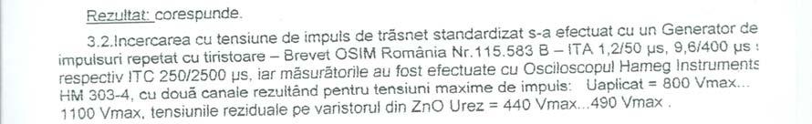

122 122
THE EXPERIMENTAL DETERMINATION OF THE MAXIMUM CONTINUOUS OPERATING VOLTAGE FOR A ZnO BASED VARISTOR
 1 2 THE EXPERIMENTAL DETERMINATION OF THE MAXIMUM CONTINUOUS OPERATING VOLTAGE FOR A ZnO BASED VARISTOR FRIGURA-ILIASA Flaviu Mihai, ZENG Eva, POPA Cristian Mihai POLITEHNICA UNIVERSITY OF TIMISOARA, ELECTRICAL
ABOUT ESTABLISHING THE FUNCTIONAL LIMITS OF A ZnO VARISTOR BASED SURGE-ARRESTER
 ABOUT ESTABLISHING THE FUNCTIONAL LIMITS OF A ZnO VARISTOR BASED SURGE-ARRESTER FLORENTIN MUNTEANU, FLAVIU-MIHAI FRIGURA-ILIASA, EMIL CAZACU 2 Key words: Functional limits, ZnO varistor, Surge-arrester.
The Experimental Determination of the Maximum Continuous Operating Voltage for a ZnO Based Varistor
 ANALELE UNIVERSITĂŢII EFTIMIE MURGU REŞIŢA ANUL XII, NR. 1, 2005, ISSN 1453-7394 ZENG Eva, POPA Cristian Mihai The Experimental Determination of the Maximum Continuous Operating Voltage for a ZnO Based
ASPECTS REGARDING NUMERICAL MODELING OF INDUCTIVE HEATING PROCESS FOR LOW VOLTAGE ELECTRICAL CABLES
 U.P.B. Sci. Bull., Series C, Vol. 72, Iss. 3, 2010 ISSN 1454-234x ASPECTS REGARDING NUMERICAL MODELING OF INDUCTIVE HEATING PROCESS FOR LOW VOLTAGE ELECTRICAL CABLES Costel PĂUN 1 În această lucrare se
STRUCTURAL PARASITIC CAPACITANCE REDUCTION TECHNIQUES IN PLANAR MAGNETIC INTEGRATED STRUCTURES
 STRUCTURAL PARASITIC CAPACITANCE REDUCTION TECHNIQUES IN PLANAR MAGNETIC INTEGRATED STRUCTURES STRUCTURAL PARASITIC CAPACITANCE REDUCTION TECHNIQUES IN PLANAR MAGNETIC INTEGRATED STRUCTURES Lecturer Eng.
PERMANENT RESEARCH POSITION CHARGE DE RECHERCHE OPEN (M/F) in Geostatistics
 in Geostatistics") PERMANENT RESEARCH POSITION CHARGE DE RECHERCHE OPEN (M/F) in Geostatistics Institution : MINES ParisTech (Ecole Nationale Supérieure des Mines de Paris) Research Center : Centre de Géosciences In the
PERMANENT RESEARCH POSITION CHARGE DE RECHERCHE OPEN (M/F) in Geostatistics Institution : MINES ParisTech (Ecole Nationale Supérieure des Mines de Paris) Research Center : Centre de Géosciences In the
ANALYSIS OF ELECTROMAGNETIC FIELDS IN INTERCONNECTING SUBSTATIONS BETWEEN WTG AND NATIONAL POWER SYSTEM
 U..B. Sci. Bull., Series C, Vol. 76, Iss. 1, 014 ISSN 86 3540 ANALYSIS OF ELECTROMAGNETIC FIELDS IN INTERCONNECTING SUBSTATIONS BETWEEN WTG AND NATIONAL OWER SYSTEM Gabriela Nicoleta SAVA 1, Sorina COSTINAŞ
SYLLABUS 1. Study using a manual, course materials, bibliography and lecture notes 25
 SYLLABUS 1 1. Information about the program 1.1 Higher education institution University Politehnica Timisoara 1. Faculty / Department 3 Faculty of Industrial Chemistry and Environmental Engineering / CAICAM
THERMAL FIELD ANALYSIS IN DESIGN AND MANUFACTURING OF A PERMANENT MAGNET LINEAR SYNCHRONOUS MOTOR
 THERMAL FIELD ANALYSIS IN DESIGN AND MANUFACTURING OF A PERMANENT MAGNET LINEAR SYNCHRONOUS MOTOR Petar UZUNOV 1 ABSTRACT: The modern Permanent Magnet Linear Synchronous Motors (PMLSM) has a wide range
RUSSIAN CHEMICAL INDUSTRY
 RUSSIAN CHEMICAL INDUSTRY SHARE OF CHEMICAL PRODUCTS IN MANUFACTURING (% OF THE TOTAL VOLUME IN RUBLES)* INDEX OF CHEMICAL PRODUCTION BY VOLUME (% OF THE TOTAL VOLUME IN TONNES)* FIXED INVESTMENTS (% OF
Development of education and training programs using ISIS research reactor
 Development of education and training programs using ISIS research reactor F. Foulon 1, B. Lescop 1, X. Wohleber 2 1) National Institute for Nuclear Science and Technology, CEA-Saclay,France 2) Nuclear
PhD Thesis RESEARCH ON CAPACITIVE MEASUREMENT PRINCIPLES FOR LIQUID LEVELS. Abstract
 Investeşte în oameni! FONDUL SOCIAL EUROPEAN Programul Operaţional Sectorial Dezvoltarea Resurselor Umane 2007 2013 Axa prioritară: 1 Educaţia şi formarea profesională în sprijinul creşterii economice
POE Concepts and Learning Objectives
 POE Concepts and Learning Objectives Unit 1 Energy and Power Time Days: 49 days Lesson 1.1 Mechanisms (15 days): 1. Engineers and engineering technologists apply math, science, and disciplinespecific skills
DEZVOLTAREA REGIONALĂ PRIN TURISM
 DEZVOLTAREA REGIONALĂ PRIN TURISM REGIONAL DEVELOPMENT THROUGH TOURISM Andreea POPA Ph.D. Student, Bucharest Academy of Economic Studies E-mail: popa_andreea22@yahoo.com Oleg MARGINA Ph.D. Student, Bucharest
Simulation of the Mechanical Behavior of Polyethylene Pipes In The Static And Dynamic Field
 International Journal of Research in Engineering and Science (IJRES) ISSN (Online): 2320-9364, ISSN (Print): 2320-9356 Volume 5 Issue 8 ǁ August. 2017 ǁ PP. 15-21 Simulation of the Mechanical Behavior
Power System Analysis Prof. A. K. Sinha Department of Electrical Engineering Indian Institute of Technology, Kharagpur
 Power System Analysis Prof. A. K. Sinha Department of Electrical Engineering Indian Institute of Technology, Kharagpur Lecture - 9 Transmission Line Steady State Operation Welcome to lesson 9, in Power
Film Capacitors. EMI suppression capacitors. Date: June 2018
 Film Capacitors EMI suppression capacitors Date: June 2018 EPCOS AG 2018. Reproduction, publication and dissemination of this publication, enclosures hereto and the information contained therein without
Modeling of Transmission Line and Substation for Insulation Coordination Studies
 TRAINING DUBROVNIK, CROATIA - APRIL, 27-29 2009 SIMULATION & ANALYSIS OF POWER SYSTEM TRANSIENTS WITH EMTP-RV Modeling of Transmission Line and Substation for Insulation Coordination Studies Prof. Ivo
TCLT10.. Series. Optocoupler with Phototransistor Output. Vishay Semiconductors. Description. Applications. VDE Standards
 Optocoupler with Phototransistor Output Description The TCLT1.. Series consists of a phototransistor optically coupled to a gallium arsenide infraredemitting diode in a 4-lead SO6L package. The elements
Principles Of Engineering Detailed Outline
 Principles Of Engineering Detailed Outline Unit 1 Energy and Power Time Days: 115 days Lesson 1.0 Introduction to POE (15 days) 1. Introduction to classroom expectations, Engineering notebook, Pretest
FACULTATEA DE INGINERIE ELECTRICĂ. Ing. Mircea RUBA TEZĂ DE DOCTORAT DESIGN AND STUDY OF A MODULAR SWITCHED RELUCTANCE MACHINE
 FACULTATEA DE INGINERIE ELECTRICĂ Ing. Mircea RUBA TEZĂ DE DOCTORAT DESIGN AND STUDY OF A MODULAR SWITCHED RELUCTANCE MACHINE Conducător ştiinţific, Prof.dr.ing.Loránd Szabó Comisia de evaluare a tezei
TCET110.(G) up to TCET4100. Optocoupler with Phototransistor Output. Vishay Telefunken. Description. Applications. VDE Standards
 up to TCET4100. Optocoupler with Phototransistor Output. Vishay Telefunken. Description. Applications. VDE Standards") Optocoupler with Phototransistor Output Description The TCET11./ TCET2/ TCET4 consists of a phototransistor optically coupled to a gallium arsenide infrared-emitting diode in a 4-lead up to 16-lead plastic
Optocoupler with Phototransistor Output Description The TCET11./ TCET2/ TCET4 consists of a phototransistor optically coupled to a gallium arsenide infrared-emitting diode in a 4-lead up to 16-lead plastic
The Vaisala AUTOSONDE AS41 OPERATIONAL EFFICIENCY AND RELIABILITY TO A TOTALLY NEW LEVEL.
 The Vaisala AUTOSONDE AS41 OPERATIONAL EFFICIENCY AND RELIABILITY TO A TOTALLY NEW LEVEL. Weather Data Benefit For Society The four most important things about weather prediction are quality, reliability,
For the electronic measurement of current: DC, AC, pulsed..., with galvanic separation between the primary and the secondary circuit.
 Current Transducer HO-NP series I P N = 4, 6, 12, 15 A Ref: HO 4-NP, HO 6-NP, HO 12-NP, HO 15-NP For the electronic measurement of current: DC, AC, pulsed..., with galvanic separation between the primary
GIS 101: AN INTRODUCTION TO GAS INSULATED SUBSTATIONS
 GIS 101: AN INTRODUCTION TO GAS INSULATED SUBSTATIONS COURSE September 28-29, 2017 Sheraton Denver Downtown Hotel Denver, CO TAG US #EUCIEvents FOLLOW US @EUCIEvents EUCI is authorized by IACET to offer
Modular contactors for installation into distribution
 Modular contactors for installation into distribution boards Modular contactors for installation into distribution boards Modular contactor for installation into distribution board Description Modular
Evaluation of Capacitance in Motor Circuit Analysis Findings. Howard W Penrose, Ph.D., CMRP President, SUCCESS by DESIGN
 Evaluation of Capacitance in Motor Circuit Analysis Findings Howard W Penrose, Ph.D., CMRP President, SUCCESS by DESIGN Introduction The question related to the ability of low voltage testing to detect
STATUS OF THE WIGOS DEMONSTRATION PROJECTS
 STATUS OF THE WIGOS DEMONSTRATION PROJECTS Demonstration Project Morocco Strengthening Moroccan RIC Capacities (Submitted by Rabia Merrouchi, National Meteorological Service of Morocco (DMN)) February
GENERATOR INTERCONNECTION APPLICATION
 GENERATOR INTERCONNECTION APPLICATION FOR BUY-ALL/SELL-ALL PROJECTS WITH AGGREGATE GENERATOR OUTPUT OF MORE THAN 20 KW BUT LESS THAN OR EQUAL TO 1 MW Electric Utility Contact Information Great Lakes Energy
Ref: HLSR 16-PW; HLSR 32-PW; HLSR 40-PW-000; HLSR 50-PW-000,
 Digital Current Transducer HLSR-PW series I P N = 16... 50 A Ref: HLSR 16-PW; HLSR 32-PW; HLSR 40-PW-000; HLSR 50-PW-000, Bitstream output from on onboard Sigma Delta modulator. For the electronic measurement
CNY17 Series. Optocoupler with Phototransistor Output. Vishay Telefunken. Description. Applications. VDE Standards.
 Optocoupler with Phototransistor Output Description The CNY7 series consists of a phototransistor optically coupled to a gallium arsenide infrared-emitting diode in a 6-lead plastic dual inline package.
1. Explain the various methods of methods of grounding. In power system, grounding or earthing means connecting frame of electrical equipment (non-cur
 1. Explain the various methods of methods of grounding. In power system, grounding or earthing means connecting frame of electrical equipment (non-current carrying part) or some electrical part of the
EXPERT SYSTEM FOR POWER TRANSFORMER DIAGNOSIS
 EXPERT SYSTEM FOR POWER TRANSFORMER DIAGNOSIS Virginia Ivanov Maria Brojboiu Sergiu Ivanov University of Craiova Faculty of Electrical Engineering 107 Decebal Blv., 200440, Romania E-mail: vivanov@elth.ucv.ro
Water Hammer Simulation For Practical Approach
 Water Hammer Simulation For Practical Approach C.D.Gălăţanu (1), Th.Mateescu (2) expert-grup@xnet.ro mateh@tuiasi.ro Technical University Gh.Asachi, Faculty of Civil Engineering, Department of Building
AN APPROACH TO THE NONLINEAR LOCAL PROBLEMS IN MECHANICAL STRUCTURES
 U.P.B. Sci. Bull., Series D, Vol. 74, Iss. 3, 2012 ISSN 1454-2358 AN APPROACH TO THE NONLINEAR LOCAL PROBLEMS IN MECHANICAL STRUCTURES Marius-Alexandru GROZEA 1, Anton HADĂR 2 Acest articol prezintă o
Eutelsat practice & views on long term sustainability. COPUOS/SCST - LTS Workshop Vienna, 14 February 2013
 Eutelsat practice & views on long term sustainability COPUOS/SCST - LTS Workshop Vienna, 14 February 2013 Introduction Introduction to Eutelsat Originally set up in 1977 as an intergovernmental organisation
Blue Marble University
 Blue Marble University B.S./D.Sc. 5 year Fast Track Combination Program, featuring a Bachelor Degree in Chemical Engineering and a Doctoral Degree in Chemical Engineering. (5 Year Program You Can Complete
The lightning phenomenon eventually brought to you
 The lightning phenomenon eventually brought to you French Lightning Training Center Program The Lightning Phenomenon The need for training in lightning risks Lightning is a disruptive discharge which happens
For the electronic measurement of current: DC, AC, pulsed..., with galvanic separation between the primary and the secondary circuit.
 Current Transducer LDSR 0.3-TP/SP1 I P R N = 300 ma For the electronic measurement of current: DC, AC, pulsed..., with galvanic separation between the primary and the secondary circuit. Features Closed
Evaluation of the risk of failure due to switching overvoltages of a phase to phase insulation
 Evaluation of the risk of failure due to switching overvoltages of a phase to phase insulation A. Xemard, J. Michaud, A. Guerrier, I. Uglesic, G. Levacic, M. Mesic Abstract-- The upgrade of an overhead
MSc Physics - SC530 (Under Review)
") MSc Physics - SC530 (Under Review) 1. Specific Titles 1) MSc Physics 2) Postgraduate Diploma in Physics 3) Postgraduate Certificate in Physics 2. Objectives This Programme aims at enhancing the knowledge
MSc Physics - SC530 (Under Review) 1. Specific Titles 1) MSc Physics 2) Postgraduate Diploma in Physics 3) Postgraduate Certificate in Physics 2. Objectives This Programme aims at enhancing the knowledge
DOE FUNDAMENTALS HANDBOOK ELECTRICAL SCIENCE Volume 1 of 4
 DOE-HDBK-1011/1-92 JUNE 1992 DOE FUNDAMENTALS HANDBOOK ELECTRICAL SCIENCE Volume 1 of 4 U.S. Department of Energy Washington, D.C. 20585 FSC-6910 Distribution Statement A. Approved for public release;
Electrical Connections
 Electrical Connections Developed and Published by AIMS Education Foundation This book contains materials developed by the AIMS Education Foundation. AIMS (Activities Integrating Mathematics and Science)
PART A Project summary
 PART A Project summary A.1 Project identification Project title Project acronym Name of the lead partner organisation in English Specific objective Demonstrattion AF DAF Partner 1.1. Improving innovation
Request for Empanelment
 Request for Empanelment (Empanelment is method/procedure/way to seek technical & financial or financial quotation from eligible firm/organization/academic institute to short list eligible contender for
YMCA UNIVERSITY OF SCIENCE AND TECHNOLOGY, FARIDABAD SCHEME OF STUDIES & EXAMINATIONS B.TECH 2 nd YEAR (SEMESTER IV) ELECTRICAL ENGINEERING ( )
 ELECTRICAL ENGINEERING ( )") YMCA UNIVERSITY OF SCIENCE AND TECHNOLOGY, FARIDABAD SCHEME OF STUDIES & EXAMINATIONS B.TECH 2 nd YEAR (SEMESTER IV) ELECTRICAL ENGINEERING (2017-18) Sl. Course Course Title L T P Credits CAT code No.
YMCA UNIVERSITY OF SCIENCE AND TECHNOLOGY, FARIDABAD SCHEME OF STUDIES & EXAMINATIONS B.TECH 2 nd YEAR (SEMESTER IV) ELECTRICAL ENGINEERING (2017-18) Sl. Course Course Title L T P Credits CAT code No.
CNY64/ CNY65/ CNY66. Optocoupler with Phototransistor Output. Vishay Telefunken. Description. Applications. VDE Standards
 Optocoupler with Phototransistor Output Description The CNY64/ CNY65/ CNY66 consist of a phototransistor optically coupled to a gallium arsenide infrared-emitting diode in a 4-lead plastic package. The
DRAFT PROGRAM Registration of participants, welcome coffee, exhibition tour
 DRAFT PROGRAM 20 Feb 2018 09.00-10.00 Registration of participants, welcome coffee, exhibition tour 10.00 12.00 ROUND TABLE: INTERNATIONAL COOPERATION IN THE ARCTIC PROJECTS: CHALLENGES AND OPPORTUNITIES
THE BEHAVIOUR OF ELASTOMERIC BEARINGS UNDER LOAD COMBINATIONS
 BULETINUL INSTITUTULUI POLITEHNIC DIN IAŞI Publicat de Universitatea Tehnică Gheorghe Asachi din Iaşi Tomul LX (LXIV), Fasc. 3, 2014 Secţia CONSTRUCŢII. ARHITECTURĂ THE BEHAVIOUR OF ELASTOMERIC BEARINGS
Modeling of Power System Components During Electromagnetic Transients
 Modeling of Power System Components During Electromagnetic Transients 1 Paweł Sowa, 2 Rafał Kumala and 3 Katarzyna Łuszcz 1, 2,3 Faculty of Electrical Engineering, Silesian University of Technology/ Institute
Energy saving in electromechanical equipment with power coefficient correction. Dimitris Al. Katsaprakakis Aeolian Land S.A.
 Energy saving in electromechanical equipment with power coefficient correction Dimitris Al. Katsaprakakis Aeolian Land S.A. www.aiolikigi.gr Introduction Electricity production companies (utilities) provide
Engineering Geology at University Complutense of Madrid: 30 years of postgraduate courses
 FIRST INTERNATIONAL CONFERENCE on EDUCATION and TRAINING in GEO-ENGINEERING ENGINEERING SCIENCES Constantza, Romania - June 2008 Engineering Geology at University Complutense of Madrid: 30 years of postgraduate
GIS 101: AN INTRODUCTION TO GAS INSULATED SUBSTATIONS
 GIS 101: AN INTRODUCTION TO GAS INSULATED SUBSTATIONS COURSE September 28-29, 2017 Sheraton Denver Downtown Hotel Denver, CO TAG US #EUCIEvents FOLLOW US @EUCIEvents EUCI is authorized by IACET to offer
Building capacity for gender responsive planning and budgeting, the Mozambican experience
 UNIVERSIDADE EDUARDO MONDLANE Building capacity for gender responsive planning and budgeting, the Mozambican experience Generosa Cossa José Director, Centre for Coordination of Gender Issues Eduardo Mondlane
What s the problem? A Modern Odyssey in Search of Relevance. The search for relevance. Some current drivers for new services. Some Major Applications
 A Modern Odyssey in Search of Relevance FIG Working Week, Athens, 24 May 2004 Paul Kelly ANZLIC Executive Director The search for relevance 1. New expectations for spatial services 2. Are we ready to meet
(Autonomous/ Affiliated to Anna University, Chennai) COIMBATORE DEPARTMENT OF ELECTRICAL AND ELECTRONICS ENGINEERING
 COIMBATORE DEPARTMENT OF ELECTRICAL AND ELECTRONICS ENGINEERING") (Autonomous/ Affiliated to Anna University, Chennai) COIMBATORE-641 032 DEPARTMENT OF ELECTRICAL AND ELECTRONICS ENGINEERING Semester III Academic Year: 2015-2016 Regulations 2014 COURSE PLAN Vision To
(Autonomous/ Affiliated to Anna University, Chennai) COIMBATORE-641 032 DEPARTMENT OF ELECTRICAL AND ELECTRONICS ENGINEERING Semester III Academic Year: 2015-2016 Regulations 2014 COURSE PLAN Vision To
ENSC3006 Chemical Process Thermodynamics and Kinetics Please note that this unit is not yet approved.
 Proposed New Unit: ENSC3006 Chemical Process Thermodynamics and Kinetics Please note that this unit is not yet approved. Unit Information Title: Level: 3 Type: Faculty: Resp. Org. Entity: ECM Office (00609)
4.2.1 Current, potential difference and resistance
 4.2 Electricity Electric charge is a fundamental property of matter everywhere. Understanding the difference in the microstructure of conductors, semiconductors and insulators makes it possible to design
SIMATIC Ident Industrial Identification Systems
 Related catalogs SIMATIC Ident Industrial Identification Systems Catalog ID 10 2012 Introduction System overview SIMATIC Ident 1 RFID systems for the HF frequency range SIMATIC RF200 SIMATIC RF300 MOBY
STUDY ON THE INFLUENCE OF THE STAR CONNECTION NEUTRAL ON THE ELECTRICAL TRANSFORMERS WINDINGS ON ELECTRIC- SECURITY AND ON THE ELECTRICAL NETWORK
 STUDY ON THE INFLUENE OF THE STA ONNETION NEUTAL ON THE ELETIAL TANSFOMES WINDINGS ON ELETI- SEUITY AND ON THE ELETIAL NETWOK ISTINEL POPESU, University of onstantin Brâncuşi of Tg-Jiu OZMA VASILE, University
SSC-JE EE POWER SYSTEMS: GENERATION, TRANSMISSION & DISTRIBUTION SSC-JE STAFF SELECTION COMMISSION ELECTRICAL ENGINEERING STUDY MATERIAL
 1 SSC-JE STAFF SELECTION COMMISSION ELECTRICAL ENGINEERING STUDY MATERIAL Power Systems: Generation, Transmission and Distribution Power Systems: Generation, Transmission and Distribution Power Systems:
Programme title: MChem Chemistry (Mathematical and Computational Chemistry)
") Faculty of Life Sciences Programme Specification Programme title: MChem Chemistry (Mathematical and Computational Chemistry) Academic Year: 2018/19 Degree Awarding Body: Final and interim award(s): University
Faculty of Life Sciences Programme Specification Programme title: MChem Chemistry (Mathematical and Computational Chemistry) Academic Year: 2018/19 Degree Awarding Body: Final and interim award(s): University
Improvements for Kosovo's spatial planning system / [presentation given in May 2011]
![Improvements for Kosovo's spatial planning system / [presentation given in May 2011]](/thumbs/95/122511393.jpg "Improvements for Kosovo's spatial planning system / [presentation given in May 2011]") Rochester Institute of Technology RIT Scholar Works Theses Thesis/Dissertation Collections 2011 Improvements for Kosovo's spatial planning system / [presentation given in May 2011] Luan Nushi Follow this
Rochester Institute of Technology RIT Scholar Works Theses Thesis/Dissertation Collections 2011 Improvements for Kosovo's spatial planning system / [presentation given in May 2011] Luan Nushi Follow this
5SJ4...-.HG Circuit Breakers to IEC and UL 489
 Siemens AG 009 5SJ...-.HG Circuit Breakers to IEC and UL 89 BETA Low-Voltage Circuit Protection Compliance with industry standards is a must in today's manufacturing environment. Worldwide acceptance is
SYLLABUS. Departmental Syllabus. Electromechanical Systems ELET0101. Departmental Syllabus. Departmental Syllabus. Departmental Syllabus
 SYLLABUS DATE OF LAST REVIEW: 02/2013 CIP CODE: 46.0302 SEMESTER: COURSE TITLE: COURSE NUMBER: Electromechanical Systems ELET0101 CREDIT HOURS: 3 INSTRUCTOR: OFFICE LOCATION: OFFICE HOURS: TELEPHONE: EMAIL:
ATTENUATION OF THE ACOUSTIC SCREENS IN CLOSED SPACES
 U.P.B. Sci. Bull., Series D, Vol. 69, No. 3, 007 ISSN 15-358 ATTENUATION OF THE ACOUSTIC SCREENS IN CLOSED SPACES Ioan MAGHEŢI 1, Mariana SAVU Lucrarea prezintă calculul atenuării acustice a unui ecran
Standard circuit diagram symbols Content Key opportunities for skills development
 4.2 Electricity Electric charge is a fundamental property of matter everywhere. Understanding the difference in the microstructure of conductors, semiconductors and insulators makes it possible to design
Accurate Determination of the Thermal Model Time Constant for the Electrical Servomotors
 Transilvania University of Brasov, Romania 13 th INTERNATIONAL CONFERENCE STANDARDIZATION, PROTYPES AND QUALITY: A MEANS OF BALKAN COUNTRIES COLLABORATION Brasov, Romania, November 3-4, 2016 Accurate Determination
Correlation between Lightning Impacts and Outages of Transmission Lines. H-D. BETZ Nowcast GmbH Munich Germany
 CIGRE C4 Colloquium on Power Quality and Lightning Sarajevo, Bosnia and Herzegovina, 13 16 May, 2012 Paper 01. Correlation between Lightning Impacts and Outages of Transmission Lines I. UGLEŠIĆ V. MILARDIĆ
Gyula Körtvélyessy, PhD
 Home-Office: Bimbó út 3O, Budapest Hungary H-1O22 Phone: (36)-1-316-541O Fax: (36)-1-336-0005 Mobil: (36)-20-344-0187 mailto:k.gyula@chello.hu http://members.chello.hu/k.gyula Gyula Körtvélyessy, PhD PERSONAL
Land Use in the context of sustainable, smart and inclusive growth
 Land Use in the context of sustainable, smart and inclusive growth François Salgé Ministry of sustainable development France facilitator EUROGI vice president AFIGéO board member 1 Introduction e-content+
Power capacitors in general
 INDEX Power capacitors in general..low VOLTGE CPCITORS MKP (Box )..PPM / MKP TECHNOLOGY..OPERTING CONDITION.. Voltage..mbient temperature.. Installation.. Discharge the capacitor.. Inrush current limitation..
Fig.1. Single-line diagram of the faulty
 Analysis of broken conductor with ground contact faults in medium voltage power network Dumitru TOADER, Ştefan HĂRĂGUŞ, onstantin BLAJ Politehnica University Timişoara P-ţa Victoriei nr., Romania; dtoader@et.utt.ro
NZQA registered unit standard version 2 Page 1 of 6
 Page 1 of 6 Title Demonstrate and apply knowledge of capacitance, inductance, power factor, and power factor correction Level 3 Credits 7 Purpose This unit standard covers an introduction to alternating
Fault Calculation Methods
 ELEC9713 Industrial and Commercial Power Systems Fault Calculation Methods There are two major problems that can occur in electrical systems: these are open circuits and short circuits. Of the two, the
Coupled Electromagnetic and Thermal Field Modeling of a Laboratory Busbar System
 Coupled Electromagnetic and Thermal Field Modeling of a Laboratory Busbar System Tatyana R. Radeva, Ivan S. Yatchev, Dimitar N. Karastoyanov, Nikolay I. Stoimenov, Stanislav D. Gyoshev Abstract The paper
SUMMARY OF PHD THESIS
 Investeşte în oameni! FONDUL SOCIAL EUROPEAN Programul Operaţional Sectorial Dezvoltarea Resurselor Umane 2007 2013 Axa prioritară: 1 Educaţia şi formarea profesională în sprijinul creşterii economice
3-D View on Training in Aeronautical Meteorology (University, Trainer, Student Perspectives)
") 3-D View on Training in Aeronautical Meteorology (University, Trainer, Student Perspectives) University Maria MAMAEVA (RSHU) Trainer Paul BUGEAC (ROMATSA) Student Ekaterina CHUMAK (RSHU) 3-D View: Aeronautical
3-D View on Training in Aeronautical Meteorology (University, Trainer, Student Perspectives) University Maria MAMAEVA (RSHU) Trainer Paul BUGEAC (ROMATSA) Student Ekaterina CHUMAK (RSHU) 3-D View: Aeronautical
COMPARATIVE DISCUSSION ABOUT THE DETERMINING METHODS OF THE STRESSES IN PLANE SLABS
 74 COMPARATIVE DISCUSSION ABOUT THE DETERMINING METHODS OF THE STRESSES IN PLANE SLABS Codrin PRECUPANU 3, Dan PRECUPANU,, Ștefan OPREA Correspondent Member of Technical Sciences Academy Gh. Asachi Technical
Keywords- Metal Oxide Surge Arrester, Model, Transient, Laboratory Experiment, Simulation.
 EVALUATION OF METAL OXIDE SURGE ARRESTER MODELS BASED ON LABORATORY EXPERIMENTS 1 G. A. ALONSO, 2 S. CARDENAS, 3 B. ALBA 1,2,3 High Voltage Department, Center of Research and Electro-Energetic Tests, Superior
MANAGEMENT FLOW CONTROL ROTOR INDUCTION MACHINE USING FUZZY REGULATORS
 1. Stela RUSU-ANGHEL, 2. Lucian GHERMAN MANAGEMENT FLOW CONTROL ROTOR INDUCTION MACHINE USING FUZZY REGULATORS 1-2. UNIVERSITY POLITEHNICA OF TIMISOARA, FACULTY OF ENGINEERING FROM HUNEDOARA, ROMANIA ABSTRACT:
State Atomic Energy Corporation Rosatom Russian Radiation Technologies: opportunities to success
 State Atomic Energy Corporation Rosatom Russian Radiation Technologies: opportunities to success M.Batkov, Director Radiation Technologies Program 15.04.2013 Rosatom is the largest hi-tech manufacturer
CHAPTER 3 INFLUENCE OF STATOR SLOT-SHAPE ON THE ENERGY CONSERVATION ASSOCIATED WITH THE SUBMERSIBLE INDUCTION MOTORS
 38 CHAPTER 3 INFLUENCE OF STATOR SLOT-SHAPE ON THE ENERGY CONSERVATION ASSOCIATED WITH THE SUBMERSIBLE INDUCTION MOTORS 3.1 INTRODUCTION The electric submersible-pump unit consists of a pump, powered by
OR Explain thermal breakdown in solid dielectrics. How this mechanism is
 Subject : High Voltage Engineering (2090) ITM Universe, Vadodara Electrical Engineering Department Class : Electrical Sem : th Long Questions Sr. No Question Unit No : 0 Explain Charge Simulation method
Procurement Plan. (Text in italic font is meant for instruction to staff and should be deleted in the final version of the PP)
") Public Disclosure Authorized Public Disclosure Authorized Public Disclosure Authorized Public Disclosure Authorized Plan (Text in italic font is meant for instruction to staff and should be deleted in
Public Disclosure Authorized Public Disclosure Authorized Public Disclosure Authorized Public Disclosure Authorized Plan (Text in italic font is meant for instruction to staff and should be deleted in
EMC Standards. Samuel Burri 2013, EPFL
 EMC Standards Samuel Burri 2013, EPFL Outline Introduction History Compliance Requirements Procedures Example: WLAN Standards in power networks Conclusion Samuel Burri, EPFL 2 Introduction EMC is concerned
URD Cable Fault Prediction Model
 1 URD Cable Fault Prediction Model Christopher Gubala ComEd General Engineer Reliability Analysis 2014 IEEE PES General Meeting Utility Current Practices & Challenges of Predictive Distribution Reliability
PhD in INDUSTRIAL CHEMISTRY AND CHEMICAL ENGINEERING - 33rd cycle
 PhD in INDUSTRIAL CHEMISTRY AND CHEMICAL ENGINEERING - 33rd cycle Number of scholarship offered 6 Department DIPARTIMENTO DI CHIMICA, MATERIALI E INGEGNERIA CHIMICA "GIULIO NATTA" Description of the PhD
4.2.1 Current, potential difference and resistance Standard circuit diagram symbols. Content. Key opportunities for skills development WS 1.
 4.2 Electricity Electric charge is a fundamental property of matter everywhere. Understanding the difference in the microstructure of conductors, semiconductors and insulators makes it possible to design
TC7WB66CFK,TC7WB66CL8X TC7WB67CFK,TC7WB67CL8X
 CMOS Digital Integrated Circuits Silicon Monolithic TC7WB66CFK,TC7WB66CL8X TC7WB67CFK,TC7WB67CL8X 1. Functional Description Dual SPST Bus Switch 2. General TC7WB66CFK/L8X,TC7WB67CFK/L8X The TC7WB66CFK/L8X
Electromagnetic Oscillations and Alternating Current. 1. Electromagnetic oscillations and LC circuit 2. Alternating Current 3.
 Electromagnetic Oscillations and Alternating Current 1. Electromagnetic oscillations and LC circuit 2. Alternating Current 3. RLC circuit in AC 1 RL and RC circuits RL RC Charging Discharging I = emf R
Updated: Page 1 of 6
 MASTER SYLLABUS 2018-2019 A. Academic Division: Business, Industry, and Technology B. Discipline: Electronic Engineering Technology C. Course Number and Title: ELET1510 DC Electricity D. Course Coordinator:
BACHELOR OF TECHNOLOGY DEGREE PROGRAM IN ELECTRICAL AND ELECTRONICS ENGINEERING B.Tech (Electrical and Electronics Engineering)
") BACHELOR OF TECHNOLOGY DEGREE PROGRAM IN ELECTRICAL AND ELECTRONICS ENGINEERING B.Tech (Electrical and Electronics Engineering) 2018-2022 1.1 PROGRAM CURRICULUM 1.1.1 Mandatory Courses and Credits The
BACHELOR OF TECHNOLOGY DEGREE PROGRAM IN ELECTRICAL AND ELECTRONICS ENGINEERING B.Tech (Electrical and Electronics Engineering) 2018-2022 1.1 PROGRAM CURRICULUM 1.1.1 Mandatory Courses and Credits The
BSEE REQUIREMENTS
 College of Engineering The Klipsch School of Electrical and Computer Engineering BSEE REQUIREMENTS 2014-2015 This document presents a summary of the requirements for earning a Bachelor of Science degree
PhD in URBAN PLANNING, DESIGN, AND POLICY - 34th cycle
 PhD in URBAN PLANNING, DESIGN, AND POLICY - 34th cycle Research Field: THE MULTIPLE EFFECTS OF B2C E-COMMERCE GROWTH IN ITALY: RETAIL SYSTEM EVOLUTION AND SPATIAL IMPACT. Monthly net income of PhDscholarship
Institute of Geography and Spatial Planning (Portugal
 Institute of Geography and Spatial Planning (Portugal Institutional Information (Last update at: 05/0/015) School/Department name (Native language) AESOP reg Number AESOP Member Status University Address
Concept note. High-Level Seminar: Accelerating Sustainable Energy for All in Landlocked Developing Countries through Innovative Partnerships
 Concept note High-Level Seminar: Accelerating Sustainable Energy for All in Landlocked Developing Countries through Innovative Partnerships Date: 24 and 25 October 2016 Venue: Conference Room C3, Vienna
240EQ212 - Fundamentals of Combustion and Fire Dynamics
 Coordinating unit: Teaching unit: Academic year: Degree: ECTS credits: 2018 295 - EEBE - Barcelona East School of Engineering 713 - EQ - Department of Chemical Engineering MASTER'S DEGREE IN CHEMICAL ENGINEERING
HABILITATION THESIS TEZĂ DE ABILITARE
 Politehnica University Timișoara HABILITATION THESIS TEZĂ DE ABILITARE From nanoscale effects to macroscopic quantities behavior: effects of electric and magnetic fields on two-phase media Candidate: Floriana
INSTITUTE OF AERONAUTICAL ENGINEERING (Autonomous) Dundigal, Hyderabad
 Dundigal, Hyderabad") INSTITUTE OF AERONAUTICAL ENGINEERING (Autonomous) Dundigal, Hyderabad - 00 0 Department of Electrical and Electronics Engineering TUTORIAL QUESTION BANK Course Name : HIGH VOLTAGE ENGINEERING Course Code
INSTITUTE OF AERONAUTICAL ENGINEERING (Autonomous) Dundigal, Hyderabad - 00 0 Department of Electrical and Electronics Engineering TUTORIAL QUESTION BANK Course Name : HIGH VOLTAGE ENGINEERING Course Code