Energy saving in electromechanical equipment with power coefficient correction. Dimitris Al. Katsaprakakis Aeolian Land S.A.
|
|
|
- Delilah McDaniel
- 5 years ago
- Views:
Transcription


1 Energy saving in electromechanical equipment with power coefficient correction Dimitris Al. Katsaprakakis Aeolian Land S.A.
2 Introduction Electricity production companies (utilities) provide consumers with active and reactive power for the electrical devives operation. Reactive power is mainly consumed by motors, for the creation of the required electromagnetic field for their operation. Reactive power is also consumed by transformers, fluorescent lamps, welding machines etc. The production and the transportation of reactive power implies extra loads for power generators, transmission lines, transformers, etc, leading to overloading of the electricity production and distribution system and the limitation of its ability for active power production and transportation. The electricity transportation losses and the voltage drops are also increased with the reactive power consumption.
3 Introduction The most common electrical devices that consume reactive power are met in asynchronous motors, employed in industrial production lines, as well in several devices met in the domestic and commercial sector, such as: lifts escalators electrical pumping stations wind turbines electrical vehicles air conditions refrigerators clothes washers and dryes.
4 Power coefficient If P is the active and Q the reactive power consumption in an electric system, the power coefficient of that system is defined as the ratio of the active power consumption over the apparent power, that is the vector sum of the active and reactive power: cosφ where the apparent power is defined as and P 2 tanφ P Q P Q 2 cosφ 1 1 tan 2 φ S P Q
5 Power coefficient The power coefficient (cosφ) consist an index for the reactive power consumption of an electric system. A good load exhibits power coefficient values close to unity (e.g. 0,95 0,99), while a bad load exhibits lower power coefficient values. For example, an active power demand of 100kW implies the consumption of 48,4 / 32,8 / 14kVA or reactive power if the system s power coefficient is 0,90 / 0,95 / 0,99, respectively. In practice, mean power coefficient values are calculated in electrical systems for certain time intervals, on the basis of the active and reactive energy consumption measurements.
6 Power coefficient Mean monthly power coefficient calculation example. Let the monthly energy consumptions for an electrical system be as below: reactive energy: Α = kVAh active energy: W = kWh. The mean monthly power coefficient in that case is: tanφ A W tanφ 1,301 cosφ 1 1 tan 2 φ 1 11,301 2 cosφ 0,609
7 Power coefficient Mean monthly power coefficient calculation example. In the same with the previous example system, reactive power compensation devices are introduced, and the monthly energy consumptions are measured: reactive energy: Α = kVAh active energy: W = kWh. The mean monthly power coefficient is now modified as: tanφ A W tanφ 0,476 cosφ 1 1 tan 2 φ 1 1 0,476 2 cosφ 0,903
8 Power coefficient From the above mentioned it is obvious that the power coefficient is improved, tending to unity, as the reactive power consumption is reduced, compared with the active power demand of the system. The power coefficient increase implies several benefits for the electrical system, as it will be analysed farther in this presentation. Consequently, the power coefficient correction is achieved with devices that aim at the reduction of the reactive power consumption. The transmission of the reactive power is not easy, since the arising transmission losses can be raised to a significant percentage of the initial produced reactive power. Hence, the reactive power demand should be faced locally, at the networks specific points where it is consumed.
9 Power coefficient In electrical networks the reactive power affects the system s nominal voltage. The abrupt reactive power consumption, usually met during the powering on of electrical motors, can lead to significant voltage sags in the networks. It is so concluded that the reduction of the reactive power consumption and the power coefficient correction the introduction of devices and equipments for the support of the networks nominal voltage. Such devices are the capacitors.
10 Benefits from the power coefficient correction
11 Reduction of the electricity losses The reduction of the electricity losses Δp of an electrical system, for constant active power demand, depends on the systems power coefficient. The power losses p R on a resistive resistance R which transfers current Ι, are given by the relationship: p R R I 2 If V is the voltage on the resistance, cosφ the system s power coefficient and P the active power transmitted through the resistance, then: P P V I cosφ I V cosφ Finally, the power losses are written as: p R R P V cosφ 2
12 Reduction of the electricity losses The power losses in an electrical system where the power coefficient is improved from cosφ 1 to cosφ 2 will be respectively: p R1 R P V cosφ 1 2 p R2 R P V cosφ 2 2 The specific power losses variation due to the power coefficient correction will be: Δp R p R1 p p R1 R2 Δp R 1 cos cos 2 2 φ φ 1 2

13 Reduction of the electricity losses The graphical representation of the above relationship gives the diagram below:

14 Reduction of the electricity losses cosφ 1 cosφ 2 0,90 0,93 0,95 0,97 Δp r (%) 0,600 55,56 58,38 60,11 61,74 0,625 51,77 54,84 56,72 58,48 0,650 47,84 51,15 53,19 55,10 0,675 43,75 47,32 49,52 51,58 0,700 39,51 43,35 45,71 47,92 0,725 35,11 39,23 41,76 44,14 0,750 30,56 34,96 37,67 40,22 0,775 25,85 30,56 33,45 36,16 0,800 20,99 26,00 29,09 31,98 0,825 15,97 21,31 24,58 27,66 0,850 10,80 16,46 19,94 23,21 0,875 5,48 11,48 15,17 18,63 0,900 0,00 6,35 10,25 13,91
15 Reduction of the electricity losses Using the above diagram (or table) we could see, for example, that if the power coefficient of a system increases from 62,5% to 90%, a reduction on the power losses of 51,77% will be achieved.
16 Reduction of the voltage sag The power coefficient correction leads to the reduction of the voltage sag on the transformers and the transmission lines installed before the capacitors connection point of the network. The voltage sag of a system is calculated using the following relationship: ΔV Z I ΔV R I cosφ Χ I sinφ where: Z R j X R and X are the resistive and the inductive component respectively of the complex resistance Z of the transformer or the transmission line.
17 Reduction of the voltage sag Example of the voltage sag reduction in an electrical system. A transformer operates with the following specifications: nominal power: S = 630kVA short circuit voltage: u k = 4% losses on copper: P cu = 6.500W. Short circuit voltage in a transformer is the voltage of the primary circuit when the transmitted current is the nominal one and the secondary circuit is shorted. It is given by the relationship: u k u 2 x u 2 r where u r and u x are the resistive and inductive voltage sag on the transformer.
18 Reduction of the voltage sag Example of the voltage sag reduction in an electrical system. Resistive voltage sag: u r R I V ον. P S Cu u Inductive voltage sag : u x X I V ον. u 2 k u r 2 r 6,5 630 u x 100% 3,87% 1,03% If the power coefficient is cosφ = 0,7 (sinφ = 0,71), the voltage sag on the transformer is calculated as: ΔV V ον. R I V ον. cosφ X I V ον. sin φ 3,47% u r
19 Reduction of the voltage sag Example of the voltage sag reduction in an electrical system. If the power coefficient improves to cosφ = 0,95 (sinφ = 0,31), the voltage sag on the transformer is calculated as: ΔV V ον. R I V ον. cosφ X I V ον. sin φ 2,18% hence, a reduction of the voltage drop of 1,29% is achieved. Although this reduction may seem low, it is rather important. Indeed, if the voltage drop in a system is 1,29% higher, this means that, in order to transfer the same power, the current must be raised with the same percentage.
20 Reduction of the voltage sag Example of the voltage sag reduction in an electrical system. Then, the power losses will increase as: R I R I1 I2 2 I2 I δι 1 2,60%, where δι 1,29% 2 2 R I I I 1 1 1
21 Reduction of the voltage sag The voltage drops in transmission lines is not as high as on transformers, because they exhibit lower inductive resistance. However, the reactive power transmission in a system with low power coefficient, can cause overloading of the lines and, consequently, important voltage drop, leading finally to significant reduction of the line transmission ability. If the power coefficient correction is performed closely to the motors, the lines are relieved from the reactive power transmission and high voltage drops are avoided.
22 Reduction of the voltage sag Reduction of voltage drop in power transmission lines versus the system s power coefficient and the cables size. Cable s size (mm 2 ) System s power coefficient 0,5 0,6 0,7 0,8 0,9 1,0 Transmission line ability (kw) 3 x 10 20,0 24,0 28,0 32,0 36,0 40,0 3 x 16 27,5 33,0 38,5 44,0 49,5 55,0 3 x 25 33,7 40,5 47,2 54,0 60,8 67,5 3 x 35 41,2 49,5 57,8 66,0 74,2 82,5 3 x 50 50,0 60,0 70,0 80,0 90,0 100,0 3 x 70 61,0 73,2 85,4 97,6 110,0 122,0 3 x 95 73,5 88,0 103,0 117,0 132,0 147,0 3 x ,0 102,0 119,0 136,0 153,0 170,0 3 x ,5 117,0 136,0 156,0 175,0 195,0 3 x ,0 133,0 156,0 178,0 200,0 222,0 3 x ,5 154,0 180,0 206,0 232,0 257,0
23 Reduction of the voltage sag Generally, the voltage drop in power transmission lines always implies the transmitted current equally percentage increase, for constant transmitted power. Since the resistive losses are analogous with the square of the current, the current increase leads to much higher losses increase. Resistive losses increase versus the system s power coefficient Power coefficient 1,0 0,9 0,8 0,7 0,6 0,5 Current over the nominal (%) Resistive losses over the nominal (%) From the above table we can see: If cosφ reduces from 1 to 0,7, the resistive resistances are doubled. If cosφ reduces from 1 to 0,5, the resistive resistances increase four times.
24 Increase of the systems transmission ability The power coefficient correction can lead to significant increase of the systems power transmission ability, since the transmitted loads through the lines and the transformers are reduced. In the diagram it is obvious that between two operational cases with the same apparent power (S 1 = S 2 ), in the second case, which exhibits higher power coefficient (φ 2 <φ 1 ), the active power transmission ability is higher (P 2 >P 1 ).
25 Increase of the systems transmission ability Increase of the transformers transmission ability versus the power coefficient Transformer s nominal power (kva) System s power coefficient 0,5 0,6 0,7 0,8 0,9 1,0 Transformer s active power transmission ability (kw)
26 Increase of the systems transmission ability Calculation example of the transformers transmission ability: Let s assume a transformer with nominal power of 630kVA that must take over an active power load of 500kW with power coefficient cosφ = 0,7. The transformer s transmission ability with the above power coefficient is: 630kVA x 0,7(kW/kVA) = 441kW. Hence, the transformer is not adequate in this case for the required transmitted active power. For the above active power transmission with the specific power coefficient, the required nominal power of the transformer is: 500kW / 0,7(kW/kVA) = 714,29kVA. Depending on the range of the commercially available transormers, we most probably should select a 800kVA or 1.000kVA transformer. The purchase of a larger device corresponds to high cost.
27 Increase of the systems transmission ability Calculation example of the transformers transmission ability : If for the same transformer (630kVA) and the same active power demand (500kW), the power coefficient is cosφ = 0,9, then the transformer s transmission ability is 630kVA x 0,9(kW/kVA) = 567kW. Hence, the transformer is adequate in that case.
28 Increase of the systems transmission ability If P 1 = V I cosφ 1 and P 2 = V I cosφ 2, are the transmitted active power in two cases between which only the power coefficient changes, we can define the specific variation of the transmitted active power versus the system s power coefficient: ΔP P P P 1 cosφ P2 cosφ2 The diagram of the next slide is constructed using the above relationship.


29 Increase of the systems transmission ability Diagram of the system s transmitted ability increase with the power coefficient correction


30 Increase of the systems transmission ability In the previously presented diagram we can estimate, for example, that if the power coefficient of a system increases from 0,60 to 0,90, a relative increase of the system s transmitted ability of 33,33% is achieved.
31 Increase of the systems transmission ability Systems transmitted ability increase with the power coefficient correction cosφ 1 cosφ 2 0,55 0,60 0,65 0,70 0,75 0,80 0,85 0,90 0,95 1,00 System s transmitted ability relative increase (%) 0,50 9,09 16,67 23,08 28,57 33,33 37,50 41,18 44,44 47,37 50,00 0,55 0,00 8,33 15,38 21,43 26,67 31,25 35,29 38,89 42,11 45,00 0,60 0,00 7,69 14,29 20,00 25,00 29,41 33,33 36,84 40,00 0,65 0,00 7,14 13,33 18,75 23,53 27,78 31,58 35,00 0,70 0,00 6,67 12,50 17,65 22,22 26,32 30,00 0,75 0,00 6,25 11,76 16,67 21,05 25,00 0,80 0,00 5,88 11,11 15,79 20,00 0,85 0,00 5,56 10,53 15,00 0,90 0,00 5,26 10,00 0,95 0,00 5,00 1,00 0,00
32 Methods of power coefficient correction
33 Power coefficient correction methods The power coefficient of a system is improved with the installation of capacitors that provide the consumed reactive power. The alternative methods are derived by the networks possible locations where the capacitors can be installed and they are: central compensation team compensation local compensation. For the selection of capacitors optimum installation method, a thorough system s inspection and evaluation is required.
34 Power coefficient correction methods Correction with central compensation. The capacitors are installed directly after the power transformer, on the low voltage bar. With this method the required capacitors power is the minimum one, compared to the one of the other two methods. With this method, the reactive power that passes through the transformer reduces, consequently the voltage drop and the transformer s losses reduce as well, leading to increase of the transformer s transmission ability.
35 Power coefficient correction Correction with team compensation. methods With this method the capacitors are installed before of selected parts of the electrical system. This method is selected when large inductive loads are met in system s points, long distances from the central compensation. Central compensation still remains for the rest parts of the system. The total required capacitive power with this method is higher than the one of the central compensation.
36 Power coefficient correction Correction with local compensation. methods It is applied in large loads with constant, or at least long, operational time period. It is implemented with the capacitors installation at the motors poles, with the required support of switches and fuses. The required capacitive power is much higher than the one of central compensation, since it is practically calculated on the basis of the peak loads of the devices for which it is applied. The total installation cost (capacitors, switches and fuses) is higher than the other two methods. For the abovementioned reasons, this method should be selected only in cases of considerably high power consumptions.
37 Calculation of the capacitors required nominal power
38 Calculation of the capacitors required nominal power Let P be the active power demand of a system, S 1 the corresponding apparent power and φ 1 the angle between the active and reactive power demand Q. To achieve a power coefficient correction from cosφ 1 to cosφ 2 the capacitors should provide the system with reactive power Q c given from the following relationship: Q c P tanφ 1 tanφ 2 Q c P 1 cos cosφ 2 1 φ 1 1 cos cosφ 2 2 φ 2
39 Calculation of the capacitors required nominal power For triangle connected capacitors, the required capacitive power is given by the relationship: Q c 3 V V C 2 ω C where: V C the capacitors polar voltage V the network s nominal voltage at the capacitors connection location ω = 2 π f, the network s rotational speed f the networks nominal frequency C the capacitors total capacity.
40 Calculation of the capacitors required nominal power For star connected capacitors, the required capacitive power is given by the relationship: Q c 1 3 VC V 2 ωc From the above two relationships it is concluded that the required capacitors capacity with star connection is three times higher than the one with triangle connection : C star = 3 C delta. For this reason, in reactive power compensation installations, the triangle connection is always selected for the capacitors.
41 Calculation of the capacitors required nominal power Example of parametric calculation: An electrical system operates with power coefficient cosφ 1 =0,70 (tanφ 1 =1,02) and consumes active power P. By applying the previous relationship we calculate the required capacitors power in order to improve the power coefficient as presented in the table below. cosφ 2 0,85 0,90 0,95 1,00 tanφ 2 0,62 0,48 0,33 0,00 Q c 0,40 P 0,54 P 0,69 P 1,02 P It is observed that the correction of the power coefficient from 0,90 to 1,00 requires the installation of almost double capacitive power, leading to extremely high installation cost. For this reason the power coefficient is usually corrected up to 0,90.
42 Calculation of the capacitors required nominal power Calculation of capacitors required power for central compensation: In that case, the system s total active power must be known. This power usually is derived from the power consumption duration curve. If no consumption data is available to get the duration curve, then this curve can be approached with a gradual function. The power consumption of the system is finally arisen from the division of the annual electricity consumption, known from the utility measurements, over the total operational hours, taken from the power consumption duration curve.
43 Calculation of the capacitors required nominal power Example of the required capacitors power for central compensation: The annual power consumption duration curve is approached with a three stages gradual function: stage 1 ο : operation with active power P for 100h stage 2 ο : operation with active power 0,80 P for 300h stage 3 ο : operation with active power 0,30 P for 300h. If the annual electricity consumption is W, then W = P 100h + 0,8P 300h + 0,3P 300h W = P 430h P = W/430h. If, for example, W = kWh, then P = 244,19kW.
44 Calculation of the capacitors required nominal power Example of the required capacitors power for central compensation: If the existing power coefficient (before the compensation) is cosφ 1 = 0,609 (tanφ 1 = 1,302), and we aim at its correction at cosφ 2 = 0,900 (tanφ 2 = 0,484), then the capacitors power should be: Q Q c c P tanφ 244,19 1 tanφ2 1,302 0,484 Q 199,75kVAR If V C = 400V the capacitors polar voltage and V = 380V the network s voltage, then (V C /V) 2 = 1,108. The final capacitive power is corrected as: Q c2 Q c1 Vc V 2 221,32kVAR c


45 Calculation of the capacitors required nominal power Example of the required capacitors power for team compensation: In this case consumption data is required for every part of the system that the team compensation is to be applied. For this reason, special devices, named as network s analysers must be installed in the particular parts of the system.
46 Calculation of the capacitors required nominal power Example of the required capacitors power for team compensation: In case that the electricity consumption measurements is not possible in the system s parts that we want to apply team compensation, we can work empirically as described below: we find all the necessary data of the particular system s parts (amount and power of the devices, distance from the low voltage bars, cables sizes) the devices specifications are gathered (power, rotational speeds, cosφ, nominal current) central compensation will be applied for the rest parts of the system, except the ones that team compensation is applied.
47 Calculation of the capacitors required nominal power Example of the required capacitors power for team compensation: The averaged part s power consumption is given by the relationship: P i μ P κ η i i where: κ: coefficient of simultaneous devices operation P i : the nominal power of each device μ i : loading coefficient of each device η i : efficiency of each device.


48 Calculation of the capacitors required nominal power Calculation of the capacitors required power in team compensation: Power coefficient and efficiency variation of asynchronous motors the motors load and the rotational speed.
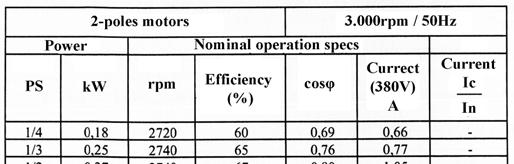
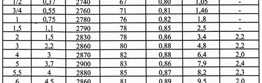
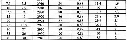
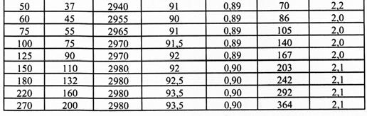
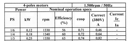
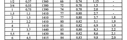
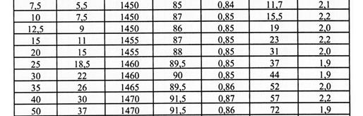
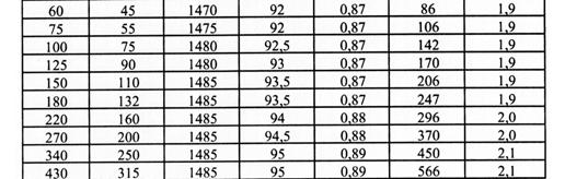
49 Calculation of the capacitors required nominal power Calculation of the capacitors required power in team compensation: Asynchronous motors specifications.


50 Calculation of the capacitors required nominal power Calculation the capacitors required power in team compensation: Asynchronous motors specifications.
51 Calculation of the capacitors required nominal power Example for the capacitors required power in team compensation: Let s assume a system s part for which the following table is constructed, after the data gathering and measuring. Motors number ν Motors power (kw) Devices capacity factor μ Power coefficient cosφ Efficiency η ν (P μ)/η cosφ ν (P μ)/η 5 3,7 0,60 0,68 0,84 13,21 8,99 2 5,5 0,75 0,78 0,87 9,48 7,40 2 7,5 0,60 0,66 0,81 11,11 7,33 2 9,0 0,65 0,73 0,84 13,93 10, ,0 0,75 0,74 0,84 13,39 9,91 Totals 61,13 43,79
52 Calculation of the capacitors required nominal power Example for the capacitors required power in team compensation: If the coefficient of the devices simultaneous operation is set κ = 0,75, then: P κ Pi μ η i i P 45,85kW For the required capacitive power calculation using the relationship: Q c P tanφ 1 tanφ 2 we should calculate the averaged power coefficient of the system s particular part. This is given by the relationship: Pi μ i νi cosφi ηi cosφ cosφ1 Pi μ i νi η 1 i 0,716
53 Calculation of the capacitors required nominal power Example for the capacitors required power in team compensation: For cosφ 1 = 0,716 it will be tanφ 1 = 0,975. If the power coefficient is attempted to be improved at cosφ 2 = 0,90 after the compensation, it will be tanφ 2 = 0,484. The required capacitive power is finally calculated by the relationship: Q Q c c P tanφ 45,83 1 tanφ2 0,975 0,484 Q 22,50kVAR If V C = 400V the capacitors polar voltage and V = 380V the network s, then (V C /V) 2 = 1,108. The final capacitive power is: Q c2 Q c1 Vc V 2 24,93kVAR c
54 Calculation of the capacitors required nominal power Capacitors required power for local reactive power compensation on transformers: The power coefficient correction is performed with the connection of capacitors with the appropriate power in the transformer s low voltage circuit. If the transformer s magnetization current is known it is possible to calculate the required capacitors power accurately.
55 Calculation of the capacitors required nominal power Capacitors required power for local reactive power compensation on transformers: Let s assume a 630kVA nominal power transformer with nominal voltage 400V. The magnetization current of the 630kVA transformer, is Ι ο = 1,8% over the transformer s nominal current. The transformer s nominal current is given by the relationship: P 3 V oν I oν Magnetization current: I oν P 3 V oν I oν V A 3 400V I oν 909,3A I o 1,8% Ι oν I o 0,018909,3 I o 16,37A
56 Calculation of the capacitors required nominal power Capacitors required power for local reactive power compensation on transformers: The consumed reactive power by the transformer is: Q c 3 V oν I o Q c 3 400V 16,37A Q c 11,34kVAR It is finally selected to install capacitors of 15kVA nominal power.
57 Calculation of the capacitors required nominal power Capacitors required power for local reactive power compensation on transformers: In case that no data are available for the capacitors (e.g. old devices), we can accept that the required capacitors power will be (the lower values correspond to larger transformers): Q c 3 V oν I o where P the transformer s nominal power. Q c 3,5 5% P In the previous example transformer, with 630kVA nominal power, the application of this empirical method would give: Q C = 0, kVA Q C = 22,05kVAR, instead of 15kVAR that was previously calculated.
58 Calculation of the capacitors required nominal power Capacitors required power for local reactive power compensation on transformers: Capacitors required power for local reactive power compensation on transformers 15/0,4kV Transformer nominal power (kva) Capacitors power (kvar) 160 5, , , , , ,0
59 Calculation of the capacitors required nominal power Example of the calculation of the required capacitors power for local compensation of welders: Resistance or arc type welders consume from the network high quantities of magnetic energy (reactive power). For this reason they are equipped with the appropriate capacitors directly by the manufacturer. In case this does not happen, and there not any available information regarding the reactive power consumption from a welder, we can assume, to simplify the calculation, a mean power coefficient of cosφ=0,45. Generally, by installing capacitors with nominal power equal to the half of the welder s nominal one, it is achieved acceptable power coefficient correction.
60 Calculation of the capacitors required nominal power Example of the calculation of the required capacitors power for local compensation of asynchronous motors: For the local reactive power compensation on asynchronous motors, the capacitors power should approach and not exceed the motors nominal power. This is imposed in order to avoid the phenomenon of power flow from the motors to the network (self excitation) and the causing of overvoltages. For this reason the required capacitive power is calculated for the reactive power compensation during motors open circuit operation (lack of load). Unfortunately the motors open circuit current Ι ο is not often mentioned in the motors specifications list. Consequently there are certain difficulties regarding the accurate calculation of the required capacitive power for motors local compensation.
61 Calculation of the capacitors required nominal power Example of the calculation of the required capacitors power for local compensation of asynchronous motors: The consumed reactive power of an asynchronous motor during its powering on, is given by the relationship: Q c 3 V oν I o The required capacitive power is calculated with the above relationship, introducing a security coefficient k = 0,85 0,90, to avoid motor s self excitation: Q c k 3 V oν I o
62 Calculation of the capacitors required nominal power Example of the calculation of the required capacitors power for local compensation of asynchronous motors: Let a motor consumes P = 30kW of active power, operating over a nominal voltage of V = 380V, and exhibiting a current for open circuit current Ι ο = 18Α. The required capacitive power is calculated as: Q c k Q c 3 V oν I o 10,66kVAR Q c 0, V 18A
63 Calculation of the capacitors required power Capacitors power for local compensation of asynchronous motors: Motor power Rotational velocity (rpm) HP kw Required capacitive power (kvar) 10 7, , ,5 7,5 7, , , , ,
64 Selection of the capacitors optimum group
65 Determining the groups power The installed capacitors in a system is usually divided into groups, in order to follow the reactive power demand variations. For the better presentation of the subject, let s assume that 35kVAR of capacitors are required for the reactive power compensation in the system. Three different capacitors groups formation will be examined: the groups power follow the ratio: 1:2:4:8, namely, the power of the following capacitors group is double than the power of the previous one the groups power follow the ratio: 1:2:2 the groups power follow the ratio: 1:1:1:1.
66 Determining the groups power The groups power follow the ratio: 1:2:4:8. In that case we can form three capacitors groups, with power 5, 10 and 20kVAR, connected to each other with an automatic relay, with the proper interruption power. With these groups we can have seven different combinations, regarding the total available capacitive power, with an increase stage of 5kVAR. The capacitors can follow quite satisfactorily the reactive power demand of the system.
67 Determining the groups power The groups power follow the ratio: 1:2:2. If we install three capacitors groups with power 7,5, 15 and 15kVAR, we can have five different combinations, regarding the total available capacitive power, with an increase stage of 7,5kVAR. The capacitors can follow quite satisfactorily the reactive power demand of the system with this formation as well.
68 Determining the groups power The groups power follow the ratio : 1:1:1:1, namely, they have the same capacitive power. The number of the different combinations that we can have is the same with the number of the groups. In our specific example, in order to reach the required capacitive power of 35kVAR, we could install four capacitors groups of 10kVAR or three groups of 10kVAR and one of 5kVAR. It is obvious that in this case the reactive power demand variation can not be followed accurately be the compensation device.
69 Comparison of the above cases At a glance it seems that the third solution must be avoided, since the arising capacity power combinations cannot coincide satisfactorily with the possible reactive power demand values. The arisen benefits from an accurate regulation of the produced capacitive power depend on the size of the compensated load. For low loads the benefits are poor. Moreover, these benefits are lost from the hard capacitors operation conditions (consecutive coupling and decoupling operations), that lead to the shortening of their life period. The same stands with the automatic switches, the contacts of which must be frequently maintained, due to the hard operating conditions. Consequently, in most cases, the reactive power compensation is approached taking into account an averaged power coefficient value, while the compensation of reactive power values exhibiting during short time intervals is out of interest.
70 Comparison of the above cases In this way, the number of the coupling and decoupling automatic operations is reduced and, more importantly, the number of the instant overvoltages, that harm the capacitors insulation and shorten their life period, is also limited. To conclude with, in practice it is usually selected a capacitive power for each capacitors group of 15 25% of the total required capacitors nominal voltage.
71 End of presentation Thank you for your attention
Week No. 6 Chapter Six: Power Factor Improvement
 Week No. 6 Chapter Six: Power Factor Improvement The electrical energy is almost wholly generated, transmitted and distributed in the form of alternating current. Therefore, the question of power factor
Power System Analysis Prof. A. K. Sinha Department of Electrical Engineering Indian Institute of Technology, Kharagpur
 Power System Analysis Prof. A. K. Sinha Department of Electrical Engineering Indian Institute of Technology, Kharagpur Lecture - 9 Transmission Line Steady State Operation Welcome to lesson 9, in Power
Brief Steady of Power Factor Improvement
 International Journal of Electrical Engineering. ISSN 0974-2158 Volume 6, Number 5 (2013), pp. 531-539 International Research PublicationHouse http://www.irphouse.com Brief Steady of Power Factor Improvement
EEE3405 ELECTRICAL ENGINEERING PRINCIPLES 2 - TEST
 ATTEMPT ALL QUESTIONS (EACH QUESTION 20 Marks, FULL MAKS = 60) Given v 1 = 100 sin(100πt+π/6) (i) Find the MS, period and the frequency of v 1 (ii) If v 2 =75sin(100πt-π/10) find V 1, V 2, 2V 1 -V 2 (phasor)
University of Jordan Faculty of Engineering & Technology Electric Power Engineering Department
 University of Jordan Faculty of Engineering & Technology Electric Power Engineering Department EE471: Electrical Machines-II Tutorial # 2: 3-ph Induction Motor/Generator Question #1 A 100 hp, 60-Hz, three-phase
Chapter 3 AUTOMATIC VOLTAGE CONTROL
 Chapter 3 AUTOMATIC VOLTAGE CONTROL . INTRODUCTION TO EXCITATION SYSTEM The basic function of an excitation system is to provide direct current to the field winding of the synchronous generator. The excitation
Fault Calculation Methods
 ELEC9713 Industrial and Commercial Power Systems Fault Calculation Methods There are two major problems that can occur in electrical systems: these are open circuits and short circuits. Of the two, the
POWER FACTOR IN THE DIGITAL AGE A N E N V I R O N M E N T A L P O T E N T I A L S W H I T E P A P E R. Power Quality For The Digital Age
 Power Quality For The Digital Age POWER FACTOR IN THE DIGITAL AGE A N E N V I R O N M E N T A L P O T E N T I A L S W H I T E P A P E R Introduction One method to measure the efficiency of the electrical
We Make Energy Engaging. Improving Your Power Factor
 We Make Energy Engaging Improving Your Power Factor Meet Your Panelist Mike Carter 2 NEEA Northwest Industrial Training Provided by: Northwest Regional Industrial Training Center: (888) 720-6823 industrial-training@industrial.neea.org
GENERATOR INTERCONNECTION APPLICATION
 GENERATOR INTERCONNECTION APPLICATION FOR BUY-ALL/SELL-ALL PROJECTS WITH AGGREGATE GENERATOR OUTPUT OF MORE THAN 20 KW BUT LESS THAN OR EQUAL TO 1 MW Electric Utility Contact Information Great Lakes Energy
Chapter 3: Fundamentals of Mechanics and Heat. 1/11/00 Electromechanical Dynamics 1
 Chapter 3: Fundamentals of Mechanics and Heat 1/11/00 Electromechanical Dynamics 1 Force Linear acceleration of an object is proportional to the applied force: F = m a x(t) F = force acting on an object
LO 1: Three Phase Circuits
 Course: EEL 2043 Principles of Electric Machines Class Instructor: Dr. Haris M. Khalid Email: hkhalid@hct.ac.ae Webpage: www.harismkhalid.com LO 1: Three Phase Circuits Three Phase AC System Three phase
KINGS COLLEGE OF ENGINEERING Punalkulam
 KINGS COLLEGE OF ENGINEERING Punalkulam 613 303 DEPARTMENT OF ELECTRICAL AND ELECTRONICS ENGINEERING POWER SYSTEM ANALYSIS QUESTION BANK UNIT I THE POWER SYSTEM AN OVERVIEW AND MODELLING PART A (TWO MARK
Electromagnetic Oscillations and Alternating Current. 1. Electromagnetic oscillations and LC circuit 2. Alternating Current 3.
 Electromagnetic Oscillations and Alternating Current 1. Electromagnetic oscillations and LC circuit 2. Alternating Current 3. RLC circuit in AC 1 RL and RC circuits RL RC Charging Discharging I = emf R
Power Factor Improvement
 Salman bin AbdulazizUniversity College of Engineering Electrical Engineering Department EE 2050Electrical Circuit Laboratory Power Factor Improvement Experiment # 4 Objectives: 1. To introduce the concept
SYNCHRONOUS GENERATOR s ROTOR INVESTIGATION OF A HYBRID POWER SYSTEM INCLUDING A.G.
 Proc. of the 5th WSEAS/IASME Int. Conf. on Electric Power Systems, High Voltages, Electric Machines, Tenerife, Spain, December 16-18, 25 (pp59-514) SYNCHRONOUS GENERATOR s ROTOR INVESTIGATION OF A HYBRID
EXEMPLAR NATIONAL CERTIFICATE (VOCATIONAL) ELECTRICAL PRINCIPLES AND PRACTICE NQF LEVEL 3 ( ) (X-Paper) 09:00 12:00
 ELECTRICAL PRINCIPLES AND PRACTICE NQF LEVEL 3 ( ) (X-Paper) 09:00 12:00") NATIONAL CERTIFICATE (VOCATIONAL) ELECTRICAL PRINCIPLES AND PRACTICE NQF LEVEL 3 2008 (12041002) (X-Paper) 09:00 12:00 EXEMPLAR This question paper consists of 7 pages. EXEMPLAR -2- NC(V) TIME: 3 HOURS
NATIONAL CERTIFICATE (VOCATIONAL) ELECTRICAL PRINCIPLES AND PRACTICE NQF LEVEL 3 2008 (12041002) (X-Paper) 09:00 12:00 EXEMPLAR This question paper consists of 7 pages. EXEMPLAR -2- NC(V) TIME: 3 HOURS
ECEN 460 Exam 1 Fall 2018
 ECEN 460 Exam 1 Fall 2018 Name: KEY UIN: Section: Score: Part 1 / 40 Part 2 / 0 Part / 0 Total / 100 This exam is 75 minutes, closed-book, closed-notes. A standard calculator and one 8.5 x11 note sheet
Chapter 1W Basic Electromagnetic Concepts
 Chapter 1W Basic Electromagnetic Concepts 1W Basic Electromagnetic Concepts 1W.1 Examples and Problems on Electric Circuits 1W.2 Examples on Magnetic Concepts This chapter includes additional examples
SSC-JE EE POWER SYSTEMS: GENERATION, TRANSMISSION & DISTRIBUTION SSC-JE STAFF SELECTION COMMISSION ELECTRICAL ENGINEERING STUDY MATERIAL
 1 SSC-JE STAFF SELECTION COMMISSION ELECTRICAL ENGINEERING STUDY MATERIAL Power Systems: Generation, Transmission and Distribution Power Systems: Generation, Transmission and Distribution Power Systems:
Three-phase AC Circuits. Measurement of Power in a Three-phase Circuit
 Three-phase AC Circuits Lesson Measurement of Power in a Three-phase Circuit In the previous lesson, the phase and line currents for balanced delta-connected load fed from a three-phase supply, along with
Power Systems - Basic Concepts and Applications - Part I
 PDHonline Course E104A (1 PDH) Power Systems - Basic Concepts and Applications - Part I Instructor: Shih-Min Hsu, Ph.D., P.E. 01 PDH Online PDH Center 57 Meadow Estates Drive Fairfax, VA 030-6658 Phone
Basics of Electric Circuits
 António Dente Célia de Jesus February 2014 1 Alternating Current Circuits 1.1 Using Phasors There are practical and economic reasons justifying that electrical generators produce emf with alternating and
SECTION 3 BASIC AUTOMATIC CONTROLS UNIT 12 BASIC ELECTRICITY AND MAGNETISM
 SECTION 3 BASIC AUTOMATIC CONTROLS UNIT 12 BASIC ELECTRICITY AND MAGNETISM Unit Objectives Describe the structure of an atom. Identify atoms with a positive charge and atoms with a negative charge. Explain
VTU E-LEARNING NOTES ON:
 VTU E-LEARNING NOTES ON: 10EE35 ELECTRICAL AND ELECTRONIC MEASUREMENTS AND INSTRUMENTATION BY DR. M.S. RAVIPRAKASHA PROFESSOR & HEAD DEPT. OF E&E ENGG. MALNAD COLLEGE OF ENGG. HASSAN 573 201. SUBJECT CODE
Power System Engineering Prof. Debapriya Das Department of Electrical Engineering Indian Institute of Technology, Kharagpur
 Power System Engineering Prof. Debapriya Das Department of Electrical Engineering Indian Institute of Technology, Kharagpur Lecture 41 Application of capacitors in distribution system (Contd.) (Refer Slide
ROEVER COLLEGE OF ENGINEERING & TECHNOLOGY ELAMBALUR, PERAMBALUR DEPARTMENT OF ELECTRICAL AND ELECTRONICS ENGINEERING ELECTRICAL MACHINES I
 ROEVER COLLEGE OF ENGINEERING & TECHNOLOGY ELAMBALUR, PERAMBALUR-621220 DEPARTMENT OF ELECTRICAL AND ELECTRONICS ENGINEERING ELECTRICAL MACHINES I Unit I Introduction 1. What are the three basic types
Analysis of AC Power RMS and Phasors Power Factor. Power Factor. Eduardo Campero Littlewood
 Power Factor Eduardo Campero Littlewood Universidad Autónoma Metropolitana Azcapotzalco Campus Energy Department Content 1 Analysis of AC Power 2 RMS and Phasors 3 Power Factor Recommended Bibliography
Energy Losses in the Electrical Circuits
 Energy Losses in the Electrical Circuits Motors, lighting systems, wiring, mechanical terminations, distribution panels, protective devices, transformers, switchgear, and all end of circuit equipment experience
Gentle synchronization of two-speed synchronous motor with asynchronous starting
 Electr Eng (2012) 94:155 163 DOI 10.1007/s00202-011-0227-1 ORIGINAL PAPER Gentle synchronization of two-speed synchronous motor with asynchronous starting Paweł Zalas Jan Zawilak Received: 5 November 2009
Chapter 21: RLC Circuits. PHY2054: Chapter 21 1
 Chapter 21: RC Circuits PHY2054: Chapter 21 1 Voltage and Current in RC Circuits AC emf source: driving frequency f ε = ε sinωt ω = 2π f m If circuit contains only R + emf source, current is simple ε ε
AC Power Analysis. Chapter Objectives:
 AC Power Analysis Chapter Objectives: Know the difference between instantaneous power and average power Learn the AC version of maximum power transfer theorem Learn about the concepts of effective or value
CHAPTER 2 OVERVOLTAGE DUE TO SELF-EXCITATION AND INRUSH CURRENT DUE TO CAPACITOR SWITCHING
 20 CHAPTER 2 OVERVOLTAGE DUE TO SELF-EXCITATION AND INRUSH CURRENT DUE TO CAPACITOR SWITCHING 2.1 INTRODUCTION It is becoming more common to find use of shunt capacitors for the application of powerfactor
Capacitor Application Issues
 Capacitor Application Issues Thomas Blooming, P.E. Daniel J. Carnovale, P.E. IEEE Industry Applications Society 53 rd Pulp & Paper Industry Technical Conf. Williamsburg, Virginia June 24-29, 2007 Introduction
1. Explain the various methods of methods of grounding. In power system, grounding or earthing means connecting frame of electrical equipment (non-cur
 1. Explain the various methods of methods of grounding. In power system, grounding or earthing means connecting frame of electrical equipment (non-current carrying part) or some electrical part of the
Lecture (5) Power Factor,threephase circuits, and Per Unit Calculations
 Power Factor,threephase circuits, and Per Unit Calculations") Lecture (5) Power Factor,threephase circuits, and Per Unit Calculations 5-1 Repeating the Example on Power Factor Correction (Given last Class) P? Q? S? Light Motor From source 1000 volts @ 60 Htz 10kW
Lecture (5) Power Factor,threephase circuits, and Per Unit Calculations 5-1 Repeating the Example on Power Factor Correction (Given last Class) P? Q? S? Light Motor From source 1000 volts @ 60 Htz 10kW
Power and Energy Measurement
 Power and Energy Measurement ENE 240 Electrical and Electronic Measurement Class 11, February 4, 2009 werapon.chi@kmutt.ac.th 1 Work, Energy and Power Work is an activity of force and movement in the direction
Lecture 11 - AC Power
 - AC Power 11/17/2015 Reading: Chapter 11 1 Outline Instantaneous power Complex power Average (real) power Reactive power Apparent power Maximum power transfer Power factor correction 2 Power in AC Circuits
coil of the circuit. [8+8]
![coil of the circuit. [8+8]](/thumbs/80/81218867.jpg "coil of the circuit. [8+8]") Code No: R05310202 Set No. 1 III B.Tech I Semester Regular Examinations, November 2008 ELECTRICAL MEASUREMENTS (Electrical & Electronic Engineering) Time: 3 hours Max Marks: 80 Answer any FIVE Questions
Code No: R05310202 Set No. 1 III B.Tech I Semester Regular Examinations, November 2008 ELECTRICAL MEASUREMENTS (Electrical & Electronic Engineering) Time: 3 hours Max Marks: 80 Answer any FIVE Questions
Prince Sattam bin Abdulaziz University College of Engineering. Electrical Engineering Department EE 3360 Electrical Machines (II)
") Chapter # 4 Three-Phase Induction Machines 1- Introduction (General Principles) Generally, conversion of electrical power into mechanical power takes place in the rotating part of an electric motor. In
Chapter # 4 Three-Phase Induction Machines 1- Introduction (General Principles) Generally, conversion of electrical power into mechanical power takes place in the rotating part of an electric motor. In
Effects of Capacitor Bank Installation in a Medium Voltage (MV) Substation
 Substation") Effects of Capacitor Bank Installation in a Medium Voltage (MV) Substation Adesina, Lambe Mutalub Department of Engineering & Standardization, Eko Electricity Distribution Plc, 24/25, Marina, Lagos Island,
Effects of Capacitor Bank Installation in a Medium Voltage (MV) Substation Adesina, Lambe Mutalub Department of Engineering & Standardization, Eko Electricity Distribution Plc, 24/25, Marina, Lagos Island,
Chapter 6: Efficiency and Heating. 9/18/2003 Electromechanical Dynamics 1
 Chapter 6: Efficiency and Heating 9/18/2003 Electromechanical Dynamics 1 Losses As a machine transforms energy from one form to another there is always a certain power loss the loss is expressed as heat,
Toolbox: Electrical Systems Dynamics
 Toolbox: Electrical Systems Dynamics Dr. John C. Wright MIT - PSFC 05 OCT 2010 Introduction Outline Outline AC and DC power transmission Basic electric circuits Electricity and the grid Image removed due
An Introduction to Electrical Machines. P. Di Barba, University of Pavia, Italy
 An Introduction to Electrical Machines P. Di Barba, University of Pavia, Italy Academic year 0-0 Contents Transformer. An overview of the device. Principle of operation of a single-phase transformer 3.
Single Phase Motors Technical Datasheets
 Single Phase Motors Technical Datasheets EN A dynamic, strong and ambitious Group: Orange1 Holding is an international renown Group, one of the most important European manufacturers of single-phase and
11. AC Circuit Power Analysis
 . AC Circuit Power Analysis Often an integral part of circuit analysis is the determination of either power delivered or power absorbed (or both). In this chapter First, we begin by considering instantaneous
Question Bank. Electric Energy, Power and Household Circuits
 Electric Energy, Power and Household Circuits 1. (a) What do you understand by the term electric work? (b) State the SI unit of electric work and define it. (c) Name two bigger units of electric work.
Single Phase Motors Technical Datasheets
 Single Phase Motors Technical Datasheets EN A dynamic, strong and ambitious Group: Orange1 Holding is an international renown Group, one of the most important European manufacturers of single-phase and
F F FAULT CURRENT Prospective. 1. Introduction. 2. Types of fault conditions
 FAULT CURRENT F F13-13 FAULT CURRENT - Contents 1. Introduction 2. Types of fault conditions 3 fault current must be determined 3.1 Purposes for which of prospective fault current magnitudes are used 3.2
TRANSFORMERS B O O K P G
 TRANSFORMERS B O O K P G. 4 4 4-449 REVIEW The RMS equivalent current is defined as the dc that will provide the same power in the resistor as the ac does on average P average = I 2 RMS R = 1 2 I 0 2 R=
Introduction to Synchronous. Machines. Kevin Gaughan
 Introduction to Synchronous Machines Kevin Gaughan The Synchronous Machine An AC machine (generator or motor) with a stator winding (usually 3 phase) generating a rotating magnetic field and a rotor carrying
PUMP PERFORMANCE MEASUREMENTS Jacques Chaurette p. eng. April 2003
 PUMP PERFORMANCE MEASUREMENTS Jacques Chaurette p. eng. www.lightmypump.com April 003 Synopsis This article examines how to take flow and pressure measurement and then calculate the total head of a pump
Study of Transient Behaviour of the Capacitor Voltage Transformer
 Study of Transient Behaviour of the Capacitor Voltage Transformer Amit Kumar 1, Dr. A. G. Thosar 2, Vivek Moroney 3 PG Student [EPS], Dept. of EE, Government College of Engineering, Aurangabad, Maharashtra,
Congestion Alleviation using Reactive Power Compensation in Radial Distribution Systems
 IOSR Journal of Electrical and Electronics Engineering (IOSR-JEEE) e-issn: 2278-1676,p-ISSN: 2320-3331, Volume 11, Issue 6 Ver. III (Nov. Dec. 2016), PP 39-45 www.iosrjournals.org Congestion Alleviation
Book Page cgrahamphysics.com Transformers
 Book Page 444-449 Transformers Review The RMS equivalent current is defined as the dc that will provide the same power in the resistor as the ac does on average P average = I 2 RMS R = 1 2 I 0 2 R= V RMS
BASIC PRINCIPLES. Power In Single-Phase AC Circuit
 BASIC PRINCIPLES Power In Single-Phase AC Circuit Let instantaneous voltage be v(t)=v m cos(ωt+θ v ) Let instantaneous current be i(t)=i m cos(ωt+θ i ) The instantaneous p(t) delivered to the load is p(t)=v(t)i(t)=v
Lecture 05 Power in AC circuit
 CA2627 Building Science Lecture 05 Power in AC circuit Instructor: Jiayu Chen Ph.D. Announcement 1. Makeup Midterm 2. Midterm grade Grade 25 20 15 10 5 0 10 15 20 25 30 35 40 Grade Jiayu Chen, Ph.D. 2
Power system conductor volume calculation
 Power system conductor volume calculation Dr Audih alfaoury T&D power systems 2017-1018 Electrical Energy Engineering Department Dr Audih alfaoury 1 The transmission of electric power is carried at high
MAHARASHTRA STATE BOARD OF TECHNICAL EDUCATION
 Important Instructions to examiners: 1) The answers should be examined by key words and not as word-to-word as given in the model answer scheme. 2) The model answer and the answer written by candidate
EE 742 Chapter 3: Power System in the Steady State. Y. Baghzouz
 EE 742 Chapter 3: Power System in the Steady State Y. Baghzouz Transmission Line Model Distributed Parameter Model: Terminal Voltage/Current Relations: Characteristic impedance: Propagation constant: π
Lecture (20) DC Machine Examples Start of Synchronous Machines
 DC Machine Examples Start of Synchronous Machines") Lecture (20) DC Machine Examples Start of Synchronous Machines Energy Systems Research Laboratory, FIU All rights reserved. 20-1 Energy Systems Research Laboratory, FIU All rights reserved. 20-2 Ra R f
Lecture (20) DC Machine Examples Start of Synchronous Machines Energy Systems Research Laboratory, FIU All rights reserved. 20-1 Energy Systems Research Laboratory, FIU All rights reserved. 20-2 Ra R f
Boise State University Department of Electrical and Computer Engineering ECE 212L Circuit Analysis and Design Lab
 Objectives Boise State University Department of Electrical and Computer Engineering ECE 22L Circuit Analysis and Design Lab Experiment #4: Power Factor Correction The objectives of this laboratory experiment
CHAPTER 5 STEADY-STATE ANALYSIS OF THREE-PHASE SELF-EXCITED INDUCTION GENERATORS
 6 CHAPTER 5 STEADY-STATE ANALYSIS OF THREE-PHASE SELF-EXCITED INDUCTION GENERATORS 5.. INTRODUCTION The steady-state analysis of six-phase SEIG has been discussed in the previous chapters. In this chapter,
INDUCTIVE-CAPACITIVE CURRENT STABILIZER POWERED BY AN ASYNCHRONOUS GENERATOR
 Journal of Engineering Studies and Research Volume 18 (01) No. 3 69 INDUCTIVE-CAPACITIVE CURRENT STABILIZER POWERED BY AN ASYNCHRONOUS GENERATOR GEORGIEV GEORGI 1*, EVSTATIEVA NADEZHDA 1, TZVETKOV ILIAN
Resistivity and Temperature Coefficients (at 20 C)
") Homework # 4 Resistivity and Temperature Coefficients (at 0 C) Substance Resistivity, Temperature ( m) Coefficient, (C ) - Conductors Silver.59 x 0-0.006 Copper.6 x 0-0.006 Aluminum.65 x 0-0.0049 Tungsten
Homework # 4 Resistivity and Temperature Coefficients (at 0 C) Substance Resistivity, Temperature ( m) Coefficient, (C ) - Conductors Silver.59 x 0-0.006 Copper.6 x 0-0.006 Aluminum.65 x 0-0.0049 Tungsten
Selecting the current rating for equipment
 Selecting the current rating for equipment 1. Rated current: the maximum continuous load current. Short-time withstand current: thermal withstand current term term is given for 1s or 3s short circuit current
J. Electrical Systems x-x (2010): x-xx. Regular paper
: x-xx. Regular paper") JBV Subrahmanyam Radhakrishna.C J. Electrical Systems x-x (2010): x-xx Regular paper A novel approach for Optimal Capacitor location and sizing in Unbalanced Radial Distribution Network for loss minimization
JBV Subrahmanyam Radhakrishna.C J. Electrical Systems x-x (2010): x-xx Regular paper A novel approach for Optimal Capacitor location and sizing in Unbalanced Radial Distribution Network for loss minimization
Fault Analysis Power System Representation
 .1. Power System Representation Single Line Diagram: Almost all modern power systems are three phase systems with the phases of equal magnitude and equal phase difference (i.e., 10 o ). These three phase
Managing Emergency Generators
 Managing Emergency Generators with nonlinear loads Author akshay thakur Application Engineer Kohler Co. Power Systems Division In this paper we will be focusing on the harmonic distortion that occurs in
Work, Energy and Power
 1 Work, Energy and Power Work is an activity of force and movement in the direction of force (Joules) Energy is the capacity for doing work (Joules) Power is the rate of using energy (Watt) P = W / t,
Energy Conversion and Management
 Energy Conversion and Management 50 (2009) 1563 1569 Contents lists available at ScienceDirect Energy Conversion and Management journal homepage: www.elsevier.com/locate/enconman Determination of aggregated
Synchronous Machines
 Synchronous Machines Synchronous Machines n 1 Φ f n 1 Φ f I f I f I f damper (run-up) winding Stator: similar to induction (asynchronous) machine ( 3 phase windings that forms a rotational circular magnetic
765kV Transmission Line for Capacity Enhancement
 International Conference on Multidisciplinary Research & Practice P a g e 200 765kV Transmission Line for Capacity Enhancement Abhilash A. Netake #, P. K. Katti * # M. Tech-II(Electrical), *Professor Electrical
Electric Machines I Three Phase Induction Motor. Dr. Firas Obeidat
 Electric Machines I Three Phase Induction Motor Dr. Firas Obeidat 1 Table of contents 1 General Principles 2 Construction 3 Production of Rotating Field 4 Why Does the Rotor Rotate 5 The Slip and Rotor
Single Phase Parallel AC Circuits
 Single Phase Parallel AC Circuits 1 Single Phase Parallel A.C. Circuits (Much of this material has come from Electrical & Electronic Principles & Technology by John Bird) n parallel a.c. circuits similar
Studies on hyper scaling dielectric loss of grading capacitors of 500kv breakers
 Studies on hyper scaling dielectric loss of grading capacitors of 500kv breakers Abstract: To solve the problem of hyper scaling dielectric loss of grading capacitors for 500 kv high voltage substation
Student Name: SE13-17 U1/2
 SE13-17 U1/2 Student Name: Unit 1 Mechanical Engineering Fundamentals Page 1. Student Learning Guide & Record Unit 1 TASK Page TASK TITLE Task 1 7 Energy Task 2 9 Draw a block diagram Task 3 16 Exercise
CHAPTER 3 ENERGY EFFICIENT DESIGN OF INDUCTION MOTOR USNG GA
 31 CHAPTER 3 ENERGY EFFICIENT DESIGN OF INDUCTION MOTOR USNG GA 3.1 INTRODUCTION Electric motors consume over half of the electrical energy produced by power stations, almost the three-quarters of the
AC Source and RLC Circuits
 X X L C = 2π fl = 1/2π fc 2 AC Source and RLC Circuits ( ) 2 Inductive reactance Capacitive reactance Z = R + X X Total impedance L C εmax Imax = Z XL XC tanφ = R Maximum current Phase angle PHY2054: Chapter
EE2351 POWER SYSTEM OPERATION AND CONTROL UNIT I THE POWER SYSTEM AN OVERVIEW AND MODELLING PART A
 EE2351 POWER SYSTEM OPERATION AND CONTROL UNIT I THE POWER SYSTEM AN OVERVIEW AND MODELLING PART A 1. What are the advantages of an inter connected system? The advantages of an inter-connected system are
ECE 325 Electric Energy System Components 7- Synchronous Machines. Instructor: Kai Sun Fall 2015
 ECE 325 Electric Energy System Components 7- Synchronous Machines Instructor: Kai Sun Fall 2015 1 Content (Materials are from Chapters 16-17) Synchronous Generators Synchronous Motors 2 Synchronous Generators
Downloaded from
 CHAPTER 12 ELECTRICITY Electricity is a general term that encompasses a variety of phenomena resulting from the presence and flow of electric charge. These include many easily recognizable phenomena such
Analyzing the Effect of Ambient Temperature and Loads Power Factor on Electric Generator Power Rating
 Analyzing the Effect of Ambient Temperature and Loads Power Factor on Electric Generator Power Rating Ahmed Elsebaay, Maged A. Abu Adma, Mahmoud Ramadan Abstract This study presents a technique clarifying
Work, Energy and Power
 1 Work, Energy and Power Work is an activity of force and movement in the direction of force (Joules) Energy is the capacity for doing work (Joules) Power is the rate of using energy (Watt) P = W / t,
Mutual Inductance. The field lines flow from a + charge to a - change
 Capacitors Mutual Inductance Since electrical charges do exist, electric field lines have a starting point and an ending point. For example, if you have a + and a - change, the field lines would look something
Review of DC Electric Circuit. DC Electric Circuits Examples (source:
 Review of DC Electric Circuit DC Electric Circuits Examples (source: http://hyperphysics.phyastr.gsu.edu/hbase/electric/dcex.html) 1 Review - DC Electric Circuit Multisim Circuit Simulation DC Circuit
Section 1 Electric Charge and Force
 CHAPTER OUTLINE Section 1 Electric Charge and Force Key Idea questions > What are the different kinds of electric charge? > How do materials become charged when rubbed together? > What force is responsible
Part 4: Electricity & Magnetism
 Part 4: Electricity & Magnetism Notes: Magnetism Magnetism Magnets: 1.Have a north and south pole 2.Like poles repel; opposite poles attract - The larger the distance between the magnets, the weaker the
ECE 476 Power System Analysis Fall 2014 Exam #1, Thursday, October 2, :30AM - 10:50AM
 ECE 476 Power System Analysis Fall 4 Exam #, Thursday, October, 4. 9:3AM - :5AM Name: Problem (5 p) Two balanced 3-phase loads are connected in parallel. One is Y-connected and draws 75 kw (3-phase) at.8
Module 3 : Sequence Components and Fault Analysis
 Module 3 : Sequence Components and Fault Analysis Lecture 12 : Sequence Modeling of Power Apparatus Objectives In this lecture we will discuss Per unit calculation and its advantages. Modeling aspects
DC Circuits. Circuits and Capacitance Worksheet. 10 Ω resistance. second? on the sodium is the same as on an electron, but positive.
 Circuits and Capacitance Worksheet DC Circuits 1. A current of 1.30 A flows in a wire. How many electrons are flowing past any point in the wire per second? 2. What is the current in amperes if 1200 Na
Transmission lines. Shouri Chatterjee. October 22, 2014
 Transmission lines Shouri Chatterjee October 22, 2014 The transmission line is a very commonly used distributed circuit: a pair of wires. Unfortunately, a pair of wires used to apply a time-varying voltage,
VTU E-LEARNING NOTES ON:
 VTU E-LEARNING NOTES ON: 10EE35 ELECTRICAL AND ELECTRONIC MEASUREMENTS AND INSTRUMENTATION BY DR. M.S. RAVIPRAKASHA PROFESSOR & HEAD DEPT. OF E&E ENGG. MALNAD COLLEGE OF ENGG. HASSAN 573 201. SUBJECT CODE
POWER SEMICONDUCTOR BASED ELECTRIC DRIVES
 POWER SEMICONDUCT BASED ELECTRIC DRIVES [Time: 3 Hrs] [Max. Marks: 80] Instructions: Solve any six questions from Q.No (1 or 2), Q.No (3 or 4), Q.No (5 or 6), Q.No (7 or 8), Q.No (9 or 10), Q.No (11 or
Optimal Capacitor Placement and Sizing on Radial Distribution System by using Fuzzy Expert System
 274 Optimal Placement and Sizing on Radial Distribution System by using Fuzzy Expert System T. Ananthapadmanabha, K. Parthasarathy, K.Nagaraju, G.V. Venkatachalam Abstract:--This paper presents a mathematical
90 MCB MODULAR CIRCUIT BREAKERS FOR CIRCUIT PROTECTION
 MCB - MTC - MT - MTHP Technical data TYPE MTC MT MTC45 MTC60 MTC100 MT 45 MT 60 Rated current (In) (A) 2-32 6-32 6-32 6-40 1-63 Utilization category A A A A A Rated operational voltage (Ue) (V) 230/400-240/415
PRINCIPLE OF DESIGN OF FOUR PHASE LOW POWER SWITCHED RELUCTANCE MACHINE AIMED TO THE MAXIMUM TORQUE PRODUCTION
 Journal of ELECTRICAL ENGINEERING, VOL. 55, NO. 5-6, 24, 138 143 PRINCIPLE OF DESIGN OF FOUR PHASE LOW POWER SWITCHED RELUCTANCE MACHINE AIMED TO THE MAXIMUM TORQUE PRODUCTION Martin Lipták This paper
OPTIMAL CAPACITOR PLACEMENT USING FUZZY LOGIC
 CHAPTER - 5 OPTIMAL CAPACITOR PLACEMENT USING FUZZY LOGIC 5.1 INTRODUCTION The power supplied from electrical distribution system is composed of both active and reactive components. Overhead lines, transformers
AC Circuits Homework Set
 Problem 1. In an oscillating LC circuit in which C=4.0 μf, the maximum potential difference across the capacitor during the oscillations is 1.50 V and the maximum current through the inductor is 50.0 ma.
FACULTY OF ENGINEERING B.E. 4/4 (EEE) II - Semester (Old) Examination, May 2014 Subject : Electrical Power Distribution Engineering (Elective- II)
 II - Semester (Old) Examination, May 2014 Subject : Electrical Power Distribution Engineering (Elective- II)") B.E. 4/4 (EEE) II - Semester (Old) Examination, May 014 Subject : Electrical Power Distribution Engineering (Elective- II) Code No. 649 / O 1 Define Coincidence factor and Diversified factor. (3) Mention
B.E. 4/4 (EEE) II - Semester (Old) Examination, May 014 Subject : Electrical Power Distribution Engineering (Elective- II) Code No. 649 / O 1 Define Coincidence factor and Diversified factor. (3) Mention