ECEN 460 Exam 1 Fall 2018
|
|
|
- Lester Collin Thomas
- 5 years ago
- Views:
Transcription
1 ECEN 460 Exam 1 Fall 2018 Name: KEY UIN: Section: Score: Part 1 / 40 Part 2 / 0 Part / 0 Total / 100 This exam is 75 minutes, closed-book, closed-notes. A standard calculator and one 8.5 x11 note sheet are allowed. Be sure to include correct units where necessary. Partial credit will be given.
2 Part I: Brief answer (4 points each) Briefly answer 9 of the following 10 questions. You may pick one to skip for full credit by circling the number. 1. What s the distinction between energy and power? Power is the time derivative of energy 2. What units for power would be appropriate for peak usage of a fast-food restaurant? kw. What is one reason AC is used for nearly all medium and large power systems today? Allows the use of transformers to change voltage levels, more efficient machines 4. What U.S. state is mostly served by its own synchronous AC interconnection? Texas 5. In Texas, what is the largest, most significant source of renewable electric energy? Wind 6. What overall effect did the Public Utilities Regulator Policies Act (PURPA) of 1978 and the National Energy Policy Act of 1992 have on the structure of the U.S. electric utility industry? Restructuring vertically integrated monopoly into regulated competitive markets 7. What major event in power engineering history happened on August 14, 200, and where? Electric power blackout in northeastern USA and eastern Canada 8. What is synchronous about a synchronous machine? The mechanical rotor speed is synchronized with the electric AC frequency 9. What two tests are used to determine an electric machine s synchronous reactance? Open circuit test and short circuit test 10. What is one phenomenon that causes power losses in transformers? Are these losses real or reactive? Possible answers: - Real losses: winding resistance, hysteresis, eddy currents - Reactive losses: leakage inductance, magnetizing current
3 Part II: Shorter calculation (6 points each) Answer each question or problem, showing your work. 1. What is the time signal corresponding to the phasor V = 2 15 kv? v(t) = 2 cos(2πft 15 ) kv 2. The current into a single-phase load is I L = A, and the voltage across the load is V L = V. What are the real power P, the reactive power Q, and the power factor pf? S L = V L I L = (100)(20 10 ) = VA = j47. VA P = W and Q = 47. var pf = cos φ = cos 10 = lagging. A three-phase delta-connected load has Z Δ = 5 + j10 Ω. What is the equivalent wyeconnected impedance? Z Y = 1 Z Δ = 5 + j10 Ω = j. Ω

4 4. What would be the steady-state mechanical speed in revolutions per minute (RPM) for an 8- pole synchronous machine connected to a 60 Hz electric grid? s mech = s elec 2 8 = 60 Hz 2 = 15 Hz = 900 RPM 8 5. The circuit below is the per-phase equivalent of a three-phase system, with the transformer turns ratio given line-to-line. Finish filling out the table below with the rest of the per-unit bases for the circuit shown. You do not need to solve the circuit. Bus 1 Bus 2 S base ( phase) 100 MVA 100 MVA V base (Line-line) 120 V 7.2 kv I base = 481 ka 100 = 8.02 ka 7.2 Z base = mω = Ω

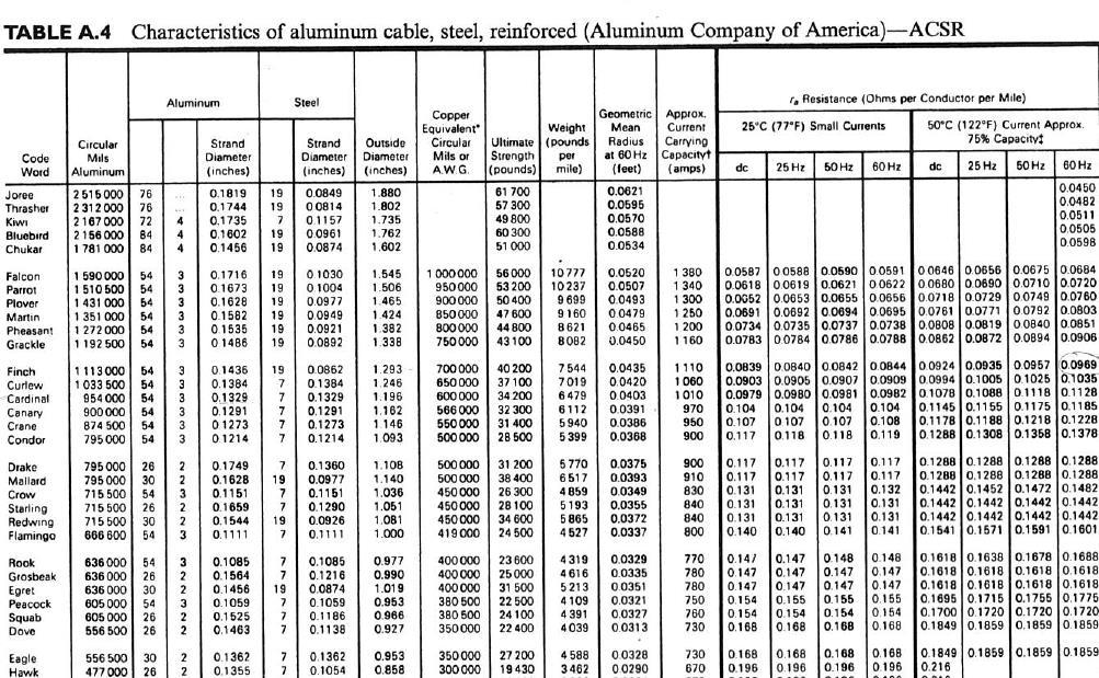
5 Part III: Longer calculation (15 points each) Solve both problems, showing detailed steps. Box in the final answers. 1. The design diagram of a newly-installed transmission line is shown below. There are three conductors bundled together at each phase, arranged with equal spacing of 10 inches. The three phase bundles are arranged vertically and spaced 8 feet apart. Assume the line is fully transposed and operated at 60 Hz. The Finch conductor is used. Calculate the per-phase, per-distance series impedance Z, a using the data from the attached conductor table. (This includes the resistance and inductance, but not the capacitance.) R = Ω mile = 0.02 Ω mile GMR = (10 in)(10 in)(0.045 ft) = 52.2 in =.74 in GMD = (8 ft)(8 ft)(76 ft) = ft X = ωl = 2πf μ 0 GMD ln 2π GMR = 2π ln = Ω m = Ω mile Z = R + jx = j Ω mile = ft ft ft
6

7 2. In the single-phase circuit below, a 120 kw load is served by a source through a transmission line with impedance Z = 5 + j18 Ω. The load has a lagging power factor of Assume the single-phase, 60 Hz system is always operated such that the load voltage is 20 kv. a. Calculate the capacitance of the capacitor that should be added in parallel with the load to correct its power factor to 0.95 lagging. b. Also calculate the real and reactive power losses in the transmission line with and without this additional capacitor. S 0.85 = P pf = 120 kw 0.85 = kva Q 0.85 = S 2 P 2 = ( kva) 2 (120 kw) 2 = 74.7 kvar S 0.95 = P pf = 120 kw 0.95 = kva Q 0.95 = S 2 P 2 = ( kva) 2 (120 kw) 2 = 9.44 kvar Hence for the capacitor: Q cap = Q 0.85 Q 0.95 = 74.7 kvar 9.44 kvar = 4.9 kvar Z cap = j V2 Q (20 kv)2 = j 4.9 kvar = j kω; C cap = 1 ωx = 1 = 21.6 nf 2π kω Without the capacitor: I = ( V ) S kva = = A 20 kv P loss = I 2 R = (7.059 A) 2 5 Ω = W Q loss = I 2 X = (7.059 A) 2 18 Ω = var With the capacitor: I = ( V ) S kva = = A 20 kv P loss = I 2 R = (6.16 A) 2 5 Ω = W Q loss = I 2 X = (6.16 A) 2 18 Ω = var
8
ECE 476 Power System Analysis Fall 2014 Exam #1, Thursday, October 2, :30AM - 10:50AM
 ECE 476 Power System Analysis Fall 4 Exam #, Thursday, October, 4. 9:3AM - :5AM Name: Problem (5 p) Two balanced 3-phase loads are connected in parallel. One is Y-connected and draws 75 kw (3-phase) at.8
University of Jordan Faculty of Engineering & Technology Electric Power Engineering Department
 University of Jordan Faculty of Engineering & Technology Electric Power Engineering Department EE471: Electrical Machines-II Tutorial # 2: 3-ph Induction Motor/Generator Question #1 A 100 hp, 60-Hz, three-phase
Introduction to Synchronous. Machines. Kevin Gaughan
 Introduction to Synchronous Machines Kevin Gaughan The Synchronous Machine An AC machine (generator or motor) with a stator winding (usually 3 phase) generating a rotating magnetic field and a rotor carrying
EEE3405 ELECTRICAL ENGINEERING PRINCIPLES 2 - TEST
 ATTEMPT ALL QUESTIONS (EACH QUESTION 20 Marks, FULL MAKS = 60) Given v 1 = 100 sin(100πt+π/6) (i) Find the MS, period and the frequency of v 1 (ii) If v 2 =75sin(100πt-π/10) find V 1, V 2, 2V 1 -V 2 (phasor)
EE 3120 Electric Energy Systems Study Guide for Prerequisite Test Wednesday, Jan 18, pm, Room TBA
 EE 3120 Electric Energy Systems Study Guide for Prerequisite Test Wednesday, Jan 18, 2006 6-7 pm, Room TBA First retrieve your EE2110 final and other course papers and notes! The test will be closed book
Synchronous Machines
 Synchronous Machines Synchronous generators or alternators are used to convert mechanical power derived from steam, gas, or hydraulic-turbine to ac electric power Synchronous generators are the primary
BASIC PRINCIPLES. Power In Single-Phase AC Circuit
 BASIC PRINCIPLES Power In Single-Phase AC Circuit Let instantaneous voltage be v(t)=v m cos(ωt+θ v ) Let instantaneous current be i(t)=i m cos(ωt+θ i ) The instantaneous p(t) delivered to the load is p(t)=v(t)i(t)=v
PROBLEM SOLUTIONS: Chapter 2
 15 PROBLEM SOLUTIONS: Chapter 2 Problem 2.1 At 60 Hz, ω = 120π. primary: (V rms ) max = N 1 ωa c (B rms ) max = 2755 V, rms secondary: (V rms ) max = N 2 ωa c (B rms ) max = 172 V, rms At 50 Hz, ω = 100π.
Brief Steady of Power Factor Improvement
 International Journal of Electrical Engineering. ISSN 0974-2158 Volume 6, Number 5 (2013), pp. 531-539 International Research PublicationHouse http://www.irphouse.com Brief Steady of Power Factor Improvement
KINGS COLLEGE OF ENGINEERING Punalkulam
 KINGS COLLEGE OF ENGINEERING Punalkulam 613 303 DEPARTMENT OF ELECTRICAL AND ELECTRONICS ENGINEERING POWER SYSTEM ANALYSIS QUESTION BANK UNIT I THE POWER SYSTEM AN OVERVIEW AND MODELLING PART A (TWO MARK
3 d Calculate the product of the motor constant and the pole flux KΦ in this operating point. 2 e Calculate the torque.
 Exam Electrical Machines and Drives (ET4117) 11 November 011 from 14.00 to 17.00. This exam consists of 5 problems on 4 pages. Page 5 can be used to answer problem 4 question b. The number before a question
Generators. What its all about
 Generators What its all about How do we make a generator? Synchronous Operation Rotor Magnetic Field Stator Magnetic Field Forces and Magnetic Fields Force Between Fields Motoring Generators & motors are
Sinusoidal Response of RLC Circuits
 Sinusoidal Response of RLC Circuits Series RL circuit Series RC circuit Series RLC circuit Parallel RL circuit Parallel RC circuit R-L Series Circuit R-L Series Circuit R-L Series Circuit Instantaneous
Lecture (5) Power Factor,threephase circuits, and Per Unit Calculations
 Power Factor,threephase circuits, and Per Unit Calculations") Lecture (5) Power Factor,threephase circuits, and Per Unit Calculations 5-1 Repeating the Example on Power Factor Correction (Given last Class) P? Q? S? Light Motor From source 1000 volts @ 60 Htz 10kW
Lecture (5) Power Factor,threephase circuits, and Per Unit Calculations 5-1 Repeating the Example on Power Factor Correction (Given last Class) P? Q? S? Light Motor From source 1000 volts @ 60 Htz 10kW
Transformer. Transformer comprises two or more windings coupled by a common magnetic circuit (M.C.).
.") . Transformers Transformer Transformer comprises two or more windings coupled by a common magnetic circuit (M.C.). f the primary side is connected to an AC voltage source v (t), an AC flux (t) will be
. Transformers Transformer Transformer comprises two or more windings coupled by a common magnetic circuit (M.C.). f the primary side is connected to an AC voltage source v (t), an AC flux (t) will be
Fault Analysis Power System Representation
 .1. Power System Representation Single Line Diagram: Almost all modern power systems are three phase systems with the phases of equal magnitude and equal phase difference (i.e., 10 o ). These three phase
LESSON 20 ALTERNATOR OPERATION OF SYNCHRONOUS MACHINES
 ET 332b Ac Motors, Generators and Power Systems LESSON 20 ALTERNATOR OPERATION OF SYNCHRONOUS MACHINES 1 LEARNING OBJECTIVES After this presentation you will be able to: Interpret alternator phasor diagrams
Chapter 4. Synchronous Generators. Basic Topology
 Basic Topology Chapter 4 ynchronous Generators In stator, a three-phase winding similar to the one described in chapter 4. ince the main voltage is induced in this winding, it is also called armature winding.
DEPARTMENT OF ELECTRICAL AND ELECTRONICS ENGINEERING QUESTION BANK
 DEPARTMENT OF ELECTRICAL AND ELECTRONICS ENGINEERING QUESTION BANK SUBJECT CODE & NAME: EE 2303 - TRANSMISSION & DISTRIBUTION YEAR / SEM: III/V UNIT-I TRANSMISSION SYSTEM INTRODUCTION PART-A 1. What is
Single Phase Parallel AC Circuits
 Single Phase Parallel AC Circuits 1 Single Phase Parallel A.C. Circuits (Much of this material has come from Electrical & Electronic Principles & Technology by John Bird) n parallel a.c. circuits similar
Power System Analysis Prof. A. K. Sinha Department of Electrical Engineering Indian Institute of Technology, Kharagpur
 Power System Analysis Prof. A. K. Sinha Department of Electrical Engineering Indian Institute of Technology, Kharagpur Lecture - 9 Transmission Line Steady State Operation Welcome to lesson 9, in Power
EE 6501 POWER SYSTEMS UNIT I INTRODUCTION
 EE 6501 POWER SYSTEMS UNIT I INTRODUCTION PART A (2 MARKS) 1. What is single line diagram? A Single line diagram is diagrammatic representation of power system in which the components are represented by
Lesson 17: Synchronous Machines
 Lesson 17: Synchronous Machines ET 332b Ac Motors, Generators and Power Systems Lesson 17_et332b.pptx 1 Learning Objectives After this presentation you will be able to: Explain how synchronous machines
AC Circuits Homework Set
 Problem 1. In an oscillating LC circuit in which C=4.0 μf, the maximum potential difference across the capacitor during the oscillations is 1.50 V and the maximum current through the inductor is 50.0 ma.
Equivalent Circuits with Multiple Damper Windings (e.g. Round rotor Machines)
") Equivalent Circuits with Multiple Damper Windings (e.g. Round rotor Machines) d axis: L fd L F - M R fd F L 1d L D - M R 1d D R fd R F e fd e F R 1d R D Subscript Notations: ( ) fd ~ field winding quantities
Equivalent Circuits with Multiple Damper Windings (e.g. Round rotor Machines) d axis: L fd L F - M R fd F L 1d L D - M R 1d D R fd R F e fd e F R 1d R D Subscript Notations: ( ) fd ~ field winding quantities
B.E. / B.Tech. Degree Examination, April / May 2010 Sixth Semester. Electrical and Electronics Engineering. EE 1352 Power System Analysis
 B.E. / B.Tech. Degree Examination, April / May 2010 Sixth Semester Electrical and Electronics Engineering EE 1352 Power System Analysis (Regulation 2008) Time: Three hours Answer all questions Part A (10
SSC-JE EE POWER SYSTEMS: GENERATION, TRANSMISSION & DISTRIBUTION SSC-JE STAFF SELECTION COMMISSION ELECTRICAL ENGINEERING STUDY MATERIAL
 1 SSC-JE STAFF SELECTION COMMISSION ELECTRICAL ENGINEERING STUDY MATERIAL Power Systems: Generation, Transmission and Distribution Power Systems: Generation, Transmission and Distribution Power Systems:
Three Phase Circuits
 Amin Electronics and Electrical Communications Engineering Department (EECE) Cairo University elc.n102.eng@gmail.com http://scholar.cu.edu.eg/refky/ OUTLINE Previously on ELCN102 Three Phase Circuits Balanced
ECE 325 Electric Energy System Components 5 Transmission Lines. Instructor: Kai Sun Fall 2015
 ECE 325 Electric Energy System Components 5 Transmission Lines Instructor: Kai Sun Fall 2015 1 Content (Materials are from Chapter 25) Overview of power lines Equivalent circuit of a line Voltage regulation
Boise State University Department of Electrical and Computer Engineering ECE 212L Circuit Analysis and Design Lab
 Objectives Boise State University Department of Electrical and Computer Engineering ECE 22L Circuit Analysis and Design Lab Experiment #4: Power Factor Correction The objectives of this laboratory experiment
Sinusoidal Steady State Power Calculations
 10 Sinusoidal Steady State Power Calculations Assessment Problems AP 10.1 [a] V = 100/ 45 V, Therefore I = 20/15 A P = 1 (100)(20)cos[ 45 (15)] = 500W, 2 A B Q = 1000sin 60 = 866.03 VAR, B A [b] V = 100/
Review of Basic Electrical and Magnetic Circuit Concepts EE
 Review of Basic Electrical and Magnetic Circuit Concepts EE 442-642 Sinusoidal Linear Circuits: Instantaneous voltage, current and power, rms values Average (real) power, reactive power, apparent power,
Review of DC Electric Circuit. DC Electric Circuits Examples (source:
 Review of DC Electric Circuit DC Electric Circuits Examples (source: http://hyperphysics.phyastr.gsu.edu/hbase/electric/dcex.html) 1 Review - DC Electric Circuit Multisim Circuit Simulation DC Circuit
THE UNIVERSITY OF NEW SOUTH WALES. School of Electrical Engineering & Telecommunications FINALEXAMINATION. Session
 Name: Student ID: Signature: THE UNIVERSITY OF NEW SOUTH WALES School of Electrical Engineering & Telecommunications FINALEXAMINATION Session 00 ELEC46 Power System Analysis TIME ALLOWED: 3 hours TOTAL
EE221 - Practice for the Midterm Exam
 EE1 - Practice for the Midterm Exam 1. Consider this circuit and corresponding plot of the inductor current: Determine the values of L, R 1 and R : L = H, R 1 = Ω and R = Ω. Hint: Use the plot to determine
ECE 325 Electric Energy System Components 7- Synchronous Machines. Instructor: Kai Sun Fall 2015
 ECE 325 Electric Energy System Components 7- Synchronous Machines Instructor: Kai Sun Fall 2015 1 Content (Materials are from Chapters 16-17) Synchronous Generators Synchronous Motors 2 Synchronous Generators
EE Branch GATE Paper 2010
 Q.1 Q.25 carry one mark each 1. The value of the quantity P, where, is equal to 0 1 e 1/e 2. Divergence of the three-dimensional radial vector field is 3 1/r 3. The period of the signal x(t) = 8 is 0.4
Power and Energy Measurement
 Power and Energy Measurement EIE 240 Electrical and Electronic Measurement April 24, 2015 1 Work, Energy and Power Work is an activity of force and movement in the direction of force (Joules) Energy is
Unit 21 Capacitance in AC Circuits
 Unit 21 Capacitance in AC Circuits Objectives: Explain why current appears to flow through a capacitor in an AC circuit. Discuss capacitive reactance. Discuss the relationship of voltage and current in
1 Phasors and Alternating Currents
 Physics 4 Chapter : Alternating Current 0/5 Phasors and Alternating Currents alternating current: current that varies sinusoidally with time ac source: any device that supplies a sinusoidally varying potential
LO 1: Three Phase Circuits
 Course: EEL 2043 Principles of Electric Machines Class Instructor: Dr. Haris M. Khalid Email: hkhalid@hct.ac.ae Webpage: www.harismkhalid.com LO 1: Three Phase Circuits Three Phase AC System Three phase
Massachusetts Institute of Technology Department of Electrical Engineering and Computer Science Electric Machines
 Massachusetts Institute of Technology Department of Electrical Engineering and Computer Science 6.685 Electric Machines Problem Set 10 Issued November 11, 2013 Due November 20, 2013 Problem 1: Permanent
SHORT QUESTIONS AND ANSWERS. Year/ Semester/ Class : III/ V/ EEE Academic Year: Subject Code/ Name: EE6501/ Power System Analysis
 Srividya colllege of Engg & Tech,Virudhunagar Sri Vidya College of Engineering And Technology Virudhunagar 626 005 Department of Electrical and Electronics Engineering QUESTION BANK SHORT QUESTIONS AND
Calculations of Capacitance for Transposed Bundled Conductor Transmission Lines
 Calculations of Capacitance for Transposed Bundled Conductor Transmission Lines Multi-conductor Lines. An example with a conductor bundle r: conductor radius, d: distance between conductors of the same
ECE 2210 Final given: Spring 15 p1
 ECE 2 Final given: Spring 15 Closed Book, Closed notes except preprinted yellow sheet, Calculators OK. Show all work to receive credit. Circle answers, show units, and round off reasonably 1. (15 pts)
mywbut.com Lesson 16 Solution of Current in AC Parallel and Seriesparallel
 esson 6 Solution of urrent in Parallel and Seriesparallel ircuits n the last lesson, the following points were described:. How to compute the total impedance/admittance in series/parallel circuits?. How
Module 3 : Sequence Components and Fault Analysis
 Module 3 : Sequence Components and Fault Analysis Lecture 12 : Sequence Modeling of Power Apparatus Objectives In this lecture we will discuss Per unit calculation and its advantages. Modeling aspects
EE 742 Chapter 3: Power System in the Steady State. Y. Baghzouz
 EE 742 Chapter 3: Power System in the Steady State Y. Baghzouz Transmission Line Model Distributed Parameter Model: Terminal Voltage/Current Relations: Characteristic impedance: Propagation constant: π
ROEVER COLLEGE OF ENGINEERING & TECHNOLOGY ELAMBALUR, PERAMBALUR DEPARTMENT OF ELECTRICAL AND ELECTRONICS ENGINEERING ELECTRICAL MACHINES I
 ROEVER COLLEGE OF ENGINEERING & TECHNOLOGY ELAMBALUR, PERAMBALUR-621220 DEPARTMENT OF ELECTRICAL AND ELECTRONICS ENGINEERING ELECTRICAL MACHINES I Unit I Introduction 1. What are the three basic types
ELECTRIC POWER CIRCUITS BASIC CONCEPTS AND ANALYSIS
 Contents ELEC46 Power ystem Analysis Lecture ELECTRC POWER CRCUT BAC CONCEPT AND ANALY. Circuit analysis. Phasors. Power in single phase circuits 4. Three phase () circuits 5. Power in circuits 6. ingle
ELG4125: Power Transmission Lines Steady State Operation
 ELG4125: Power Transmission Lines Steady State Operation Two-Port Networks and ABCD Models A transmission line can be represented by a two-port network, that is a network that can be isolated from the
Chapter 8: Unsymmetrical Faults
 Chapter 8: Unsymmetrical Faults Introduction The sequence circuits and the sequence networks developed in the previous chapter will now be used for finding out fault current during unsymmetrical faults.
Week No. 6 Chapter Six: Power Factor Improvement
 Week No. 6 Chapter Six: Power Factor Improvement The electrical energy is almost wholly generated, transmitted and distributed in the form of alternating current. Therefore, the question of power factor
EN Power Electronics and Machines
 1/19 - Power Electronics and Machines Transformers Suryanarayana Doolla Department of Energy Science and Engineering Indian Institute of Technology, Bombay suryad@iitb.ac.in Lecture Organization - Modules
GATE 2010 Electrical Engineering
 GATE 2010 Electrical Engineering Q.1 Q.25 carry one mark each 1. The value of the quantity P, where P = xe dx, is equal to (A) 0 (B) 1 (C) e (D) 1/e 2. Divergence of the three-dimensional radial vector
INSTITUTE OF AERONAUTICAL ENGINEERING (Autonomous)
") INSTITUTE OF AERONAUTICAL ENGINEERING (Autonomous) Dundigal, Hyderabad - 500 043 ELECTRICAL AND ELECTRONICS ENGINEERING QUESTION BANK Course Name : Computer Methods in Power Systems Course Code : A60222
INSTITUTE OF AERONAUTICAL ENGINEERING (Autonomous) Dundigal, Hyderabad - 500 043 ELECTRICAL AND ELECTRONICS ENGINEERING QUESTION BANK Course Name : Computer Methods in Power Systems Course Code : A60222
CHAPTER 3 ANALYSIS OF THREE PHASE AND SINGLE PHASE SELF-EXCITED INDUCTION GENERATORS
 26 CHAPTER 3 ANALYSIS OF THREE PHASE AND SINGLE PHASE SELF-EXCITED INDUCTION GENERATORS 3.1. INTRODUCTION Recently increase in energy demand and limited energy sources in the world caused the researchers
Electromagnetic Energy Conversion Exam 98-Elec-A6 Spring 2002
 Front Page Electromagnetic Energy Conversion Exam 98-Elec-A6 Spring 2002 Notes: Attempt question 1 and FOUR (4) other questions (FVE (5) questions in all). Unless you indicate otherwise, the first five
PHASOR DIAGRAM OF TRANSFORMER. Prepared By ELECTRICALBABA.COM
 PHASOR DIAGRAM OF TRANSFORMER Prepared By ELECTRICALBABA.COM IMPORTANT POINTS FOR PHASOR OF TRANSFORMER Transformer when excited at no load, only takes excitation current which leads the working Flux by
Work, Energy and Power
 1 Work, Energy and Power Work is an activity of force and movement in the direction of force (Joules) Energy is the capacity for doing work (Joules) Power is the rate of using energy (Watt) P = W / t,
Homework 2 SJTU233. Part A. Part B. Problem 2. Part A. Problem 1. Find the impedance Zab in the circuit seen in the figure. Suppose that R = 5 Ω.
 Homework 2 SJTU233 Problem 1 Find the impedance Zab in the circuit seen in the figure. Suppose that R = 5 Ω. Express Zab in polar form. Enter your answer using polar notation. Express argument in degrees.
EECE421 Power System Analysis. Chapter 4: Transmission Line Capacitance
 EECE421 Power System Analysis Chapter 4: Transmission Line Capacitance 1 Capacitance C: Capacitance Caused by the potential difference between the conductors (Charge) per (unit of potential difference)
UNIVERSITY OF SWAZILAND FACULTY OF SCIENCE DEPARTMENT OF ELECTRICAL AND ELECTRONIC ENGINEERING. MAIN EXAMINATION May 2013
 UNIVERSITY OF SWAZILAND FACULTY OF SCIENCE DEPARTMENT OF ELECTRICAL AND ELECTRONIC ENGINEERING MAIN EXAMINATION May 2013 TITLE OF PAPER: Fundamentals of Power Engineering COURSE CODE: EE 351 TIME ALLOWED:
Fault Calculation Methods
 ELEC9713 Industrial and Commercial Power Systems Fault Calculation Methods There are two major problems that can occur in electrical systems: these are open circuits and short circuits. Of the two, the
Impact Study on Power Factor of Electrical Load in Power Distribution System
 Impact Study on Power Factor of Electrical Load in Power Distribution System Syirrazie CS 1, H.Hasim 1 Ahmad Asraf AS 2 1 Bahagian Sokongan Teknikal, Agensi Nuklear Malaysia 2 University of Western Australia
REACTANCE. By: Enzo Paterno Date: 03/2013
 REACTANCE REACTANCE By: Enzo Paterno Date: 03/2013 5/2007 Enzo Paterno 1 RESISTANCE - R i R (t R A resistor for all practical purposes is unaffected by the frequency of the applied sinusoidal voltage or
Power and Energy Measurement
 Power and Energy Measurement ENE 240 Electrical and Electronic Measurement Class 11, February 4, 2009 werapon.chi@kmutt.ac.th 1 Work, Energy and Power Work is an activity of force and movement in the direction
Transformer Fundamentals
 Transformer Fundamentals 1 Introduction The physical basis of the transformer is mutual induction between two circuits linked by a common magnetic field. Transformer is required to pass electrical energy
Three-phase AC Circuits. Measurement of Power in a Three-phase Circuit
 Three-phase AC Circuits Lesson Measurement of Power in a Three-phase Circuit In the previous lesson, the phase and line currents for balanced delta-connected load fed from a three-phase supply, along with
Basics of Electric Circuits
 António Dente Célia de Jesus February 2014 1 Alternating Current Circuits 1.1 Using Phasors There are practical and economic reasons justifying that electrical generators produce emf with alternating and
04-Electric Power. ECEGR 452 Renewable Energy Systems
 04-Electric Power ECEGR 452 Renewable Energy Systems Overview Review of Electric Circuits Phasor Representation Electrical Power Power Factor Dr. Louie 2 Introduction Majority of the electrical energy
Analyzing the Effect of Ambient Temperature and Loads Power Factor on Electric Generator Power Rating
 Analyzing the Effect of Ambient Temperature and Loads Power Factor on Electric Generator Power Rating Ahmed Elsebaay, Maged A. Abu Adma, Mahmoud Ramadan Abstract This study presents a technique clarifying
Pb1 y13 =-j10 Pb5. Pb4. y34 =-j10
 EE 55, Exam, ake-home. Due Monday, April, 06, 5:00pm. You may use class notes or any reference materials (e.g., books, etc.) that you like; however, you must work alone, i.e., you should not be communicating
Chapter 3 AUTOMATIC VOLTAGE CONTROL
 Chapter 3 AUTOMATIC VOLTAGE CONTROL . INTRODUCTION TO EXCITATION SYSTEM The basic function of an excitation system is to provide direct current to the field winding of the synchronous generator. The excitation
EE2351 POWER SYSTEM ANALYSIS UNIT I: INTRODUCTION
 EE2351 POWER SYSTEM ANALYSIS UNIT I: INTRODUCTION PART: A 1. Define per unit value of an electrical quantity. Write equation for base impedance with respect to 3-phase system. 2. What is bus admittance
Power System Engineering Prof. Debapriya Das Department of Electrical Engineering Indian Institute of Technology, Kharagpur
 Power System Engineering Prof. Debapriya Das Department of Electrical Engineering Indian Institute of Technology, Kharagpur Lecture 41 Application of capacitors in distribution system (Contd.) (Refer Slide
An Introduction to Electrical Machines. P. Di Barba, University of Pavia, Italy
 An Introduction to Electrical Machines P. Di Barba, University of Pavia, Italy Academic year 0-0 Contents Transformer. An overview of the device. Principle of operation of a single-phase transformer 3.
Chapter 1W Basic Electromagnetic Concepts
 Chapter 1W Basic Electromagnetic Concepts 1W Basic Electromagnetic Concepts 1W.1 Examples and Problems on Electric Circuits 1W.2 Examples on Magnetic Concepts This chapter includes additional examples
ECE 421/521 Electric Energy Systems Power Systems Analysis I 2 Basic Principles. Instructor: Kai Sun Fall 2013
 ECE 41/51 Electric Energy Systems Power Systems Analysis I Basic Principles Instructor: Kai Sun Fall 013 1 Outline Power in a 1-phase AC circuit Complex power Balanced 3-phase circuit Single Phase AC System
Transmission and Distribution of Electrical Power
 KINGDOM OF SAUDI ARABIA Ministry Of High Education Umm Al-Qura University College of Engineering & Islamic Architecture Department Of Electrical Engineering Transmission and Distribution of Electrical
Module 3 : Sequence Components and Fault Analysis
 Module 3 : Sequence Components and Fault Analysis Lecture 13 : Sequence Modeling (Tutorial) Objectives In this lecture we will solve tutorial problems on fault analysis in sequence domain Per unit values
Voltage Deviation of Wind Power Generation due to Wind Velocity Change
 Proceedings of the 7th WSEAS International Conference on Power Systems, Beijing, China, September 15-17, 2007 242 Voltage Deviation of Wind Power Generation due to Wind Velocity Change JUNICHI ARAI, Department
BEF BEF Chapter 2. Outline BASIC PRINCIPLES 09/10/2013. Introduction. Phasor Representation. Complex Power Triangle.
 BEF 5503 BEF 5503 Chapter BASC PRNCPLES Outline 1 3 4 5 6 7 8 9 ntroduction Phasor Representation Coplex Power Triangle Power Factor Coplex Power in AC Single Phase Circuits Coplex Power in Balanced Three-Phase
CHAPTER 2 CAPACITANCE REQUIREMENTS OF SIX-PHASE SELF-EXCITED INDUCTION GENERATORS
 9 CHAPTER 2 CAPACITANCE REQUIREMENTS OF SIX-PHASE SELF-EXCITED INDUCTION GENERATORS 2.. INTRODUCTION Rapidly depleting rate of conventional energy sources, has led the scientists to explore the possibility
ECE 476. Exam #2. Tuesday, November 15, Minutes
 Name: Answers ECE 476 Exam #2 Tuesday, November 15, 2016 75 Minutes Closed book, closed notes One new note sheet allowed, one old note sheet allowed 1. / 20 2. / 20 3. / 20 4. / 20 5. / 20 Total / 100
Module 4. Single-phase AC circuits. Version 2 EE IIT, Kharagpur
 Module 4 Single-phase circuits ersion EE T, Kharagpur esson 6 Solution of urrent in Parallel and Seriesparallel ircuits ersion EE T, Kharagpur n the last lesson, the following points were described:. How
11. AC Circuit Power Analysis
 . AC Circuit Power Analysis Often an integral part of circuit analysis is the determination of either power delivered or power absorbed (or both). In this chapter First, we begin by considering instantaneous
2 Signal Frequency and Impedances First Order Filter Circuits Resonant and Second Order Filter Circuits... 13
 Lecture Notes: 3454 Physics and Electronics Lecture ( nd Half), Year: 7 Physics Department, Faculty of Science, Chulalongkorn University //7 Contents Power in Ac Circuits Signal Frequency and Impedances
ECE 201 Fall 2009 Final Exam
 ECE 01 Fall 009 Final Exam December 16, 009 Division 0101: Tan (11:30am) Division 001: Clark (7:30 am) Division 0301: Elliott (1:30 pm) Instructions 1. DO NOT START UNTIL TOLD TO DO SO.. Write your Name,
Lecture 11 - AC Power
 - AC Power 11/17/2015 Reading: Chapter 11 1 Outline Instantaneous power Complex power Average (real) power Reactive power Apparent power Maximum power transfer Power factor correction 2 Power in AC Circuits
ECE 420. Review of Three Phase Circuits. Copyright by Chanan Singh, Panida Jirutitijaroen, and Hangtian Lei, For educational use only-not for sale.
 ECE 40 Review of Three Phase Circuits Outline Phasor Complex power Power factor Balanced 3Ф circuit Read Appendix A Phasors and in steady state are sinusoidal functions with constant frequency 5 0 15 10
UNIT I INTRODUCTION Part A- Two marks questions
 ROEVER COLLEGE OF ENGINEERING & TECHNOLOGY ELAMBALUR, PERAMBALUR-621220 DEPARTMENT OF ELECTRICAL AND ELECTRONICS ENGINEERING DESIGN OF ELECTRICAL MACHINES UNIT I INTRODUCTION 1. Define specific magnetic
= 32.0\cis{38.7} = j Ω. Zab = Homework 2 SJTU233. Part A. Part B. Problem 2. Part A. Problem 1
 Homework 2 SJTU233 Problem 1 Find the impedance Zab in the circuit seen in the figure. Suppose that R = 5 Ω. Express Zab in polar form. Enter your answer using polar notation. Express argument in degrees.
JRE SCHOOL OF Engineering
 JRE SCHOOL OF Engineering Class Test-1 Examinations September 2014 Subject Name Electromechanical Energy Conversion-II Subject Code EEE -501 Roll No. of Student Max Marks 30 Marks Max Duration 1 hour Date
TRANSMISSION LINES. All aluminum alloy conductor (AAAC) Aluminum conductor alloy reinforced (ACAR)
 Aluminum conductor alloy reinforced (ACAR)") TRANSMISSION LINES. Transmission Structures An overhead transmission line consists of conductor, insulators, support structures and in most cases shield wires. Overhead power transmission lines are classified
TRANSMISSION LINES. Transmission Structures An overhead transmission line consists of conductor, insulators, support structures and in most cases shield wires. Overhead power transmission lines are classified
Q. 1 Q. 5 carry one mark each.
 GATE 2016 General Aptitude - GA Set-6 Q. 1 Q. 5 carry one mark each. Q.1 The man who is now Municipal Commissioner worked as. (A) the security guard at a university (B) a security guard at the university
Control of Wind Turbine Generators. James Cale Guest Lecturer EE 566, Fall Semester 2014 Colorado State University
 Control of Wind Turbine Generators James Cale Guest Lecturer EE 566, Fall Semester 2014 Colorado State University Review from Day 1 Review Last time, we started with basic concepts from physics such as
THREE-PHASE CIRCUITS. Historical Profiles
 C H A P T E R THREE-PHASE CIRCUITS 1 2 Society is never prepared to receive any invention. Every new thing is resisted, and it takes years for the inventor to get people to listen to him and years more
ECEN 667 Power System Stability Lecture 18: Voltage Stability, Load Models
 ECEN 667 Power System Stability Lecture 18: Voltage Stability, Load Models Prof. Tom Overbye Dept. of Electrical and Computer Engineering Texas A&M University, overbye@tamu.edu 1 Announcements Read Chapter
Electrical Circuits Lab Series RC Circuit Phasor Diagram
 Electrical Circuits Lab. 0903219 Series RC Circuit Phasor Diagram - Simple steps to draw phasor diagram of a series RC circuit without memorizing: * Start with the quantity (voltage or current) that is