Force System Resultants. Engineering Mechanics: Statics
|
|
|
- Sophie Summers
- 6 years ago
- Views:
Transcription

1 Force System Resultants Engineering Mechanics: Statics
2 Chapter Objectives To discuss the concept of the moment of a force and show how to calculate it in 2-D and 3-D systems. Definition of the moment of a couple.
3 Chapter Objectives To present methods for determining the resultants of non-concurrent force systems in 2D and 3D systems. Reducing the given system of forces and couple moments into an equivalent force and couple moment at any point.
4 Chapter Outline Moment of a Force Force Couple Principles of Moments

5 Moment of a Force Carpenters often use a hammer in this way to pull a stubborn nail. Through what sort of action does the force F H at the handle pull the nail? How can you mathematically model the effect of force F H at point O?
 is a")

6 Moment of a Force 2D System Moment of a force about a point (or an axis) is a measure of the tendency of the force to cause a body to rotate about the point or axis.

7 Case 1: Moment of a Force 2D System F x horizontal and acts perpendicular to the handle of the wrench and is located d y from the point O F x tends to turn the pipe about the z axis The larger the force or the distance d y the greater the turning effect

8 Moment of a Force 2D System The larger the force W or the distance D the greater the turning effect at point P.
9 Note that: Moment of a Force 2D System Moment axis (z) is perpendicular to shaded plane (x-y). i.e. The remaining third axis: z F x and d y lies on the shaded plane (x-y) Moment axis (z) intersects the plane at point O
moment along (M o ) x.")
10 Moment of a Force 2D System Case 2: Apply force F z to the wrench Pipe does not rotate about z axis The pipe not actually rotates but F z creates a tendency for rotation so causing (producing)moment along (M o ) x. Moment axis (x) is perpendicular to the shaded plane (y-z) F z and d y lies on the shaded plane (y-z)
11 Moment of a Force 2D System Case 3: Apply force F y to the wrench No moment is produced about point O Lack of tendency to rotate as line of action passes through O Note that, F y and d y both lies on the same line (and not forming any plane) hence No Moment is produced.

12 Moment of a force does not always cause rotation Force F; Moment of a Force 2D System tends to rotate the beam clockwise about A with moment M A = d A F tends to rotate the beam counterclockwise about B with moment M B = d B F
13 In General Moment of a Force 2D System Consider the force F and the point O which lies in the shaded plane The moment M O about point O, or about an axis passing through O and which is perpendicular to the plane, is a vector quantity.
14 Moment of a Force 2D System Moment M O is a vector having specified magnitude and direction.
15 Moment of a Force 2D System M = F x d M = Magnitude of the moment about point or axis [N.m] F= Magnitude of the force [N] d = perpendicular distance [m] Direction is determined by using the right hand rule

16 Moment of a Force 2D System Positive direction of the moment : Anti clockwise

17 Moment of a Force 2D System Positive moment Negative moment
18 Magnitude: Moment of a Force 2D System Scalar Formulation Use simple multiplication; For magnitude of M O : M O = F. d d = moment arm or perpendicular distance from the axis at point O to its line of action of the force. F = Magnitude of the force Units for moment is N.m, kn.m
19 Direction: Moment of a Force 2D System Scalar Formulation Direction of M O is specified by using right hand rule Fingers of the right hand are curled to follow the sense of rotation when force rotates about point O.
20 Direction: Moment of a Force 2D System Scalar Formulation Thumb points along the moment axis to give the direction and sense of the moment vector Moment vector is upwards and perpendicular to the shaded plane
21 Moment of a Force 2D System Scalar Formulation Direction M O is shown by a vector arrow with a curl to distinguish it from force vector Fig b. M O is represented by the counterclockwise curl, which indicates the action of F. Arrowhead shows the sense of rotation caused by F. Using the right hand rule, the direction and sense of the moment vector points out of the page.
22 Moment of a Force 2D System Vector Formulation In some two dimensional problems and most of the three dimensional problems, it is convenient to use a vector approach for moment calculations. The MOMENT of a force about point A may be represented by the cross product expression. M r F r Position vector which runs from the moment reference point to any point on the line of action of the force.
23 Moment of a Force 2D System Vector Formulation Without using the right hand rule directly apply the equation through cross product of vectors. M O = d X F The cross product directly gives the magnitude and the direction. Units for moment is N.m, kn.m
 r y F x")
24 Sarrus Rule Moment of a Force 2D System Vector Formulation M o r F - k +k M o r x F y ( k) r y F x ( k)
25 Example: Moment of a Force 2D System For each case, determine the moment of the force about point O
26 Solution Line of action is extended as a dashed line to establish moment arm d Tendency to rotate is indicated and the orbit is shown as a colored curl (a)m (2m)(100N) N.m (CW) o (b)m (0.75m)(50N) N.m (CW) o Moment of a Force 2D System
27 Solution (c) M (4m 2cos30 m)(40n) N.m (CW) o (d) M (1sin 45 m)(60n) N.m (CCW) o (e) M (4m 1m)(7kN) kn.m (CCW) o Moment of a Force 2D System
28 Moment of a Force 2D System Example: Determine the moments of the 800 N force acting on the frame about points A, B, C and D.
29 Moment of a Force 2D System Solution (Scalar Analysis) M = (2.5m)(800N) = 2000 N.m (CW) A M = (1.5m)(800N) = 1200 N.m (CW) B M = (0m)(800N)= 0 N.m C Line of action of F passes through C M = (0.5m)(800N) = 400 N.m (CCW) D
30 Moment of a Force 2D System
31 Principles of Moments Principles of Moments Also known as Varignon s Theorem This principle states that the moment of a force about a point is equal to the sum of moments of the force s components about the point.
32 Principles of Moments Moment of a force about a point is equal to the sum of the moments of the forces components about the point

33 Principles of Moments
34 Principles of Moments Solution Method 1: From trigonometry using triangle BCD, CB = d = 100cos45 = mm Thus, M A =df= ( m) 200N = N.mm (CCW) = N.m (CCW) As a Cartesian vector, M A = { k} N.m
35 Principles of Moments Solution Method 2: Resolve 200 N force into x and y components Principle of Moments M A = df M A =(200)(200sin45 ) (100)(200cos45 ) = N.mm (CCW) = N.m (CCW)


36 Principles of Moments Example: Moment of a force about a point is equal to the sum of the moments of the forces components about the point d 3 sin m M O Fd 5 cos 45 3sin 30 5 sin 45 3cos kn m kn m M O F d x y F y d x
37 Moment of a Force 2D System Example: The force F acts at the end of the angle bracket. Determine the moment of the force about point O.
38 Solution Method 1: Resolve the given force into components and than apply the moment equation. M O = 400sin30 N(0.2m)-400cos30 N(0.4m) = N.m Moment of a Force 2D System As a Cartesian vector, M O = { k} N.m
39 Solution Method 2: Express as Cartesian vector r = {0.4i 0.2j} m F = {400sin30 i 400cos30 j} N = { i j}N For moment, O i j k M rxf Moment of a Force 2D System k N.m
40 Moment of a Force 2D System Example (T): Determine the moment of the 600 N force with respect to point O in both scalar and vector product approaches.
. M Ro = F.")
41 Resultant Moment of System of Coplanar Forces Resultant moment M Ro = addition of the moments produced by all the forces algebraically since all moment forces are collinear (for 2D case). M Ro = F.d taking counterclockwise (CCW), to be positive.
. M Ro =M 1 M 2 + M 3 = df= d 1 F 1 d 2 F 2 + d 3 F 3 taking counterclockwise (CCW) to be positive.")
42 Resultant Moment of System of Coplanar Forces Resultant moment, M Ro = addition of the moments produced by all the forces algebraically, since all moment forces are collinear (for 2D case). M Ro =M 1 M 2 + M 3 = df= d 1 F 1 d 2 F 2 + d 3 F 3 taking counterclockwise (CCW) to be positive.

43 Resultant Moment of System of Coplanar Forces M + R O Fd Counterclockwise is positive
44 Resultant Moment of System of Coplanar Forces Example: Determine the resultant moment of the four forces acting on the rod about point O.
45 Solution: (by scalar analysis) Note that always positive moments acts in the +k direction, CCW M F.d M Ro Ro ( 50N)(2m) (60N)(0m) (20N)(3sin 30 (40N)(4m 3cos N.m N.m (CW) Resultant Moment of System of Coplanar Forces m) m)
46 Solution: (by vector analysis) M Ro M Ro dxf Resultant Moment of System of Coplanar Forces [2(i)X 50 (-j)] [0X 60 (i)] [3sin30 (-j)x 20 (i)] [ (4 3cos30 )(i)x 40 (-j)] [100( k)] [0] [30(k)] [ (-k)] N.m(-k) or(cw)

47 Moment (Revision)

48 Moment Moment force F about point O can be expressed using cross product M O = r X F where r represents position vector from O to any point lying on the line of action of F.
49 Moment Remember M = r (vector) X F (vector) Find the length r vectorially for each force F if not given, find the vectorial representation of F also.
50 Moment In some two dimensional problems and many three dimensional problems, it is convenient to use a vector approach for moment calculations. The MOMENT of a force about point A may be represented by the cross product expression M r F
51 Moment A M A r 3 r 2 r 1 F r F M r F Position vector which runs from the moment reference point to any point on the line of action of the force Due to the principle of transmissibility, can act at any point along its line of action and still create the same moment about point A. M A r1 F r2 F r3 F
 F = r F because the cross product of the parallel vectors u and F is")
52 The Moment Vector The result obtained from r X F doesn t depend on where the vector r intersects the line of action of F: r = r + u r F = (r + u) F = r F because the cross product of the parallel vectors u and F is zero.
53 Moment of a Couple Couple - two parallel forces - same magnitude but opposite direction - separated by perpendicular distance d Resultant force = 0 Tendency to rotate in specified direction Couple moment = sum of moments of both couple forces about any arbitrary point

54 Moment of a Couple The moment of a couple is defined as: A couple is defined as two parallel forces with the same magnitude but opposite in direction separated by a perpendicular distance d. M O = F. d (using a scalar analysis; right hand rule for direction), M O = d X F (using vector analysis).

55 Moment of a Couple The net external effect of a couple is zero since the net force equals zero and the magnitude of the net moment equals F.d The moment of a couple is a free vector. It can be moved anywhere on the body and have the same external effect on the body. Moments due to couples can be added using the same rules as adding any vectors.
56 Moment of a Couple 2D A O a d B F F C M O = F (a+d) F a = F d M O =M A =M B =M C Moment of a couple has the same value for all moment centers.
57 Moment of a Couple 2D M M 2D CCW couple M M 2D CW couple

58 Moment of a Couple 2D = The moment of a couple is a free vector. It can be moved anywhere on the body and have the same external effect on the body.

59 Moment of a Couple 2D APPLICATIONS

60 Moment of a Couple 2D APPLICATIONS (continued)
61 Moment of a Couple 2D Scalar Formulation Magnitude of couple moment M = F.d Direction and sense are determined by right hand rule In all cases, M acts perpendicular to plane containing the forces.
62 Moment of a Couple 2D Vectorial Formulation M = d X F In all cases, M acts perpendicular to plane containing the forces.
63 Moment of a Couple 2D Example: A couple acts on the gear teeth. Replace it by an equivalent couple having a pair of forces that act through points A and B. =

64 Moment of a Couple 2D Solution Magnitude of couple M = 24 N.m Direction out of the page since forces tend to rotate CCW M is a free vector and can be placed anywhere.
65 Solution Moment of a Couple 2D To preserve CCW motion, vertical forces acting through points A and B must be directed as shown For magnitude of each force, M = F.d 24 N.m = F (0.2m) F = N

66 Example (T): Moment of a Couple 2D
67 Moment of a Couple 2D Equivalent Couples Two different couples are equivalent if they produce the same moment, (magnitude as well as direction).
68 Moment of a Couple 2D Two couples are equivalent if they produce the same moment with magnitude and direction. = =

69 Example (T): Moment of a Couple 2D
Chapter -4- Force System Resultant
 Ishik University / Sulaimani Civil Engineering Department Chapter -4- Force System Resultant 1 2 1 CHAPTER OBJECTIVES To discuss the concept of the moment of a force and show how to calculate it in two
Ishik University / Sulaimani Architecture Department Structure ARCH 214 Chapter -4- Force System Resultant
 Ishik University / Sulaimani Architecture Department 1 Structure ARCH 214 Chapter -4- Force System Resultant 2 1 CHAPTER OBJECTIVES To discuss the concept of the moment of a force and show how to calculate
ENGR-1100 Introduction to Engineering Analysis. Lecture 9
 ENGR-1100 Introduction to Engineering Analysis Lecture 9 MOMENT OF A FORCE (SCALAR FORMULATION), CROSS PRODUCT, MOMENT OF A FORCE (VECTOR FORMULATION), & PRINCIPLE OF MOMENTS Today s Objectives : Students
MOMENT OF A FORCE ABOUT A POINT
 MOMENT OF A FORCE ABOUT A POINT The tendency of a body to rotate about an axis passing through a specific point O when acted upon by a force (sometimes called a torque). 1 APPLICATIONS A torque or moment
SKAA 1213 Engineering Mechanics
 SKAA 1213 Engineering Mechanics TPIC 5 Moment and Couple Lecturers: Rosli Anang Dr. Mohd Yunus Ishak Dr. Tan Cher Siang Moment of a Force Moment of a force about a point/axis the tendency of the force
Moment of a force (scalar, vector ) Cross product Principle of Moments Couples Force and Couple Systems Simple Distributed Loading
 Cross product Principle of Moments Couples Force and Couple Systems Simple Distributed Loading") Chapter 4 Moment of a force (scalar, vector ) Cross product Principle of Moments Couples Force and Couple Systems Simple Distributed Loading The moment of a force about a point provides a measure of the
Chapter 4 Moment of a force (scalar, vector ) Cross product Principle of Moments Couples Force and Couple Systems Simple Distributed Loading The moment of a force about a point provides a measure of the
2. Force Systems. 2.1 Introduction. 2.2 Force
 2. Force Systems 2.1 Introduction 2.2 Force - A force is an action of one body on another. - A force is an action which tends to cause acceleration of a body (in dynamics). - A force is a vector quantity.
ENGINEERING MECHANICS BAA1113. Chapter 4: Force System Resultants (Static)
") ENGINEERING MECHANICS BAA1113 Chapter 4: Force System Resultants (Static) by Pn Rokiah Bt Othman Faculty of Civil Engineering & Earth Resources rokiah@ump.edu.my Chapter Description Aims To explain the
ENGINEERING MECHANICS BAA1113 Chapter 4: Force System Resultants (Static) by Pn Rokiah Bt Othman Faculty of Civil Engineering & Earth Resources rokiah@ump.edu.my Chapter Description Aims To explain the
Equivalent Force Systems
 Equivalent Force Systems EQUIVALENT SYSTEMS for SINGLE FORCE Determining the effect of moving a force. 1. MOVING A FORCE ON ITS LINE OF ACTION 2. MOVING A FORCE OFF OF ITS LINE OF ACTION Equivalent Force
ARC241 Structural Analysis I Lecture 5, Sections ST4.5 ST4.10
 Lecture 5, Sections ST4.5 ST4.10 ST4.5) Moment of a Force about a Specified Axis ST4.6) Moment of a Couple ST4.7) Equivalent System ST4.8) Resultant of a Force and a Couple System ST4.9) Further Reduction
MOMENT OF A COUPLE. Today s Objectives: Students will be able to. a) define a couple, and, b) determine the moment of a couple.
 define a couple, and, b) determine the moment of a couple.") Today s Objectives: Students will be able to MOMENT OF A COUPLE a) define a couple, and, b) determine the moment of a couple. In-Class activities: Check Homework Reading Quiz Applications Moment of a Couple
Today s Objectives: Students will be able to MOMENT OF A COUPLE a) define a couple, and, b) determine the moment of a couple. In-Class activities: Check Homework Reading Quiz Applications Moment of a Couple
two forces and moments Structural Math Physics for Structures Structural Math
 RHITETURL STRUTURES: ORM, EHVIOR, ND DESIGN DR. NNE NIHOLS SUMMER 05 lecture two forces and moments orces & Moments rchitectural Structures 009abn Structural Math quantify environmental loads how big is
Ishik University / Sulaimani Civil Engineering Department. Chapter -2-
 Ishik University / Sulaimani Civil Engineering Department Chapter -- 1 orce Vectors Contents : 1. Scalars and Vectors. Vector Operations 3. Vector Addition of orces 4. Addition of a System of Coplanar
Chapter 12 Static Equilibrium
 Chapter Static Equilibrium. Analysis Model: Rigid Body in Equilibrium. More on the Center of Gravity. Examples of Rigid Objects in Static Equilibrium CHAPTER : STATIC EQUILIBRIUM AND ELASTICITY.) The Conditions
MECHANICS. Prepared by Engr. John Paul Timola
 MECHANICS Prepared by Engr. John Paul Timola MECHANICS a branch of the physical sciences that is concerned with the state of rest or motion of bodies that are subjected to the action of forces. subdivided
Engineering Mechanics: Statics in SI Units, 12e Force Vectors
 Engineering Mechanics: Statics in SI Units, 1e orce Vectors 1 Chapter Objectives Parallelogram Law Cartesian vector form Dot product and angle between vectors Chapter Outline 1. Scalars and Vectors. Vector
five moments ELEMENTS OF ARCHITECTURAL STRUCTURES: FORM, BEHAVIOR, AND DESIGN DR. ANNE NICHOLS SPRING 2014 lecture ARCH 614
 ELEMENTS OF ARCHITECTURAL STRUCTURES: FORM, BEHAVIOR, AND DESIGN DR. ANNE NICHOLS SPRING 2014 lecture five moments Moments 1 Moments forces have the tendency to make a body rotate about an axis http://www.physics.umd.edu
MOMENT OF A COUPLE. Today s Objectives: Students will be able to a) define a couple, and, b) determine the moment of a couple.
 define a couple, and, b) determine the moment of a couple.") MOMENT OF A COUPLE Today s Objectives: Students will be able to a) define a couple, and, b) determine the moment of a couple. In Class activities: Check Homework Reading Quiz Applications Moment of a Couple
MOMENT OF A COUPLE Today s Objectives: Students will be able to a) define a couple, and, b) determine the moment of a couple. In Class activities: Check Homework Reading Quiz Applications Moment of a Couple
acting on a body has two effects:
 The force acting on a body has two effects: the first one is the tendency to push or pull the body in the direction of the force, and the second one is to rotate the body about any fixed axis which does
Chapter -4- Force System Resultant
 Ishik University / Sulaimani Civil Engineering Department Chapter -4- Force System Resultant 1 4.3 MOMENT OF A COUPLE Couple - two parallel forces. - same magnitude but opposite direction. - separated
Engineering Mechanics: Statics
 Engineering Mechanics: Statics Chapter 2: Force Systems Part A: Two Dimensional Force Systems Force Force = an action of one body on another Vector quantity External and Internal forces Mechanics of Rigid
Force Couple Systems = Reduction of a Force to an Equivalent Force and Moment (Moving a Force to Another Point) acting on a body has two effects:
 acting on a body has two effects:") ESULTANTS orce Couple Systems = eduction of a orce to an Equivalent orce and Moment (Moving a orce to Another Point) The force acting on a body has two effects: the first one is the tendency to push or
ESULTANTS orce Couple Systems = eduction of a orce to an Equivalent orce and Moment (Moving a orce to Another Point) The force acting on a body has two effects: the first one is the tendency to push or
2.1 Scalars and Vectors
 2.1 Scalars and Vectors Scalar A quantity characterized by a positive or negative number Indicated by letters in italic such as A e.g. Mass, volume and length 2.1 Scalars and Vectors Vector A quantity
CIV100: Mechanics. Lecture Notes. Module 1: Force & Moment in 2D. You Know What to Do!
 CIV100: Mechanics Lecture Notes Module 1: Force & Moment in 2D By: Tamer El-Diraby, PhD, PEng. Associate Prof. & Director, I2C University of Toronto Acknowledgment: Hesham Osman, PhD and Jinyue Zhang,
Torque. Objectives. Assessment. Assessment. Equations. Physics terms 6/2/14
 Objectives Calculate torque given the lever arm (perpendicular distance) and the force. Calculate torque in newton meters and in pound feet. Interpret positive and negative signs in the context of torque.
Chapter Objectives. Copyright 2011 Pearson Education South Asia Pte Ltd
 Chapter Objectives To show how to add forces and resolve them into components using the Parallelogram Law. To express force and position in Cartesian vector form and explain how to determine the vector
Chapter 4 Force System Resultant Moment of a Force
 Chapter 4 Force System Resultant Moment of a Force MOMENT OF A FORCE SCALAR FORMULATION, CROSS PRODUCT, MOMENT OF A FORCE VECTOR FORMULATION, & PRINCIPLE OF MOMENTS Today s Objectives : Students will be
Engineering Mechanics Prof. U. S. Dixit Department of Mechanical Engineering Indian Institute of Technology, Guwahati
 Engineering Mechanics Prof. U. S. Dixit Department of Mechanical Engineering Indian Institute of Technology, Guwahati Module No. - 01 Basics of Statics Lecture No. - 01 Fundamental of Engineering Mechanics
DOT PRODUCT. Statics, Fourteenth Edition in SI Units R.C. Hibbeler. Copyright 2017 by Pearson Education, Ltd. All rights reserved.
 DOT PRODUCT Today s Objective: Students will be able to use the vector dot product to: a) determine an angle between two vectors and, b) determine the projection of a vector along a specified line. In-Class
Example 25: Determine the moment M AB produced by force F in Figure which tends to rotate the rod about the AB axis.
 Eample 25: Determine the moment M AB produced by force F in Figure which tends to rotate the rod about the AB ais. Solution: Because that F is parallel to the z-ais so it has no moment about z-ais. Its
Introduction /Basic concept
 GCHAPTER 1 Introduction /Basic concept MECHANICS: Mechanics can be defined as the branch of physics concerned with the state of rest or motion of bodies that subjected to the action of forces. OR It may
Chapter 8. Rotational Equilibrium and Rotational Dynamics
 Chapter 8 Rotational Equilibrium and Rotational Dynamics Force vs. Torque Forces cause accelerations Torques cause angular accelerations Force and torque are related Torque The door is free to rotate about
Mengetahui dan memahami maksud dari momen gaya, momen kopel, dan cara. Apa yang dipelajari sekarang? memindah gaya MOMEN DAN KOPEL
 MOMEN DAN KOPEL Apa yang dipelajari sekarang? Mengetahui dan memahami maksud dari momen gaya, momen kopel, dan cara memindah gaya Apa itu momen gaya? The moment of a force about a point provides a measure
VELAMMAL COLLEGE OF ENGINEERING AND TECHNOLOGY MADURAI DEPARTMRNT OF MECHANICAL ENGINEERING. Subject Code. Mechanics
 VELAMMAL COLLEGE OF ENGINEERING AND TECHNOLOGY MADURAI 625 009 DEPARTMRNT OF MECHANICAL ENGINEERING Year / Sem / Branch I Year / II Sem / CSE Subject Code GE 204 Subject Name Engineering Mechanics Faculty
Course Overview. Statics (Freshman Fall) Dynamics: x(t)= f(f(t)) displacement as a function of time and applied force
 Dynamics: x(t)= f(f(t)) displacement as a function of time and applied force") Course Overview Statics (Freshman Fall) Engineering Mechanics Dynamics (Freshman Spring) Strength of Materials (Sophomore Fall) Mechanism Kinematics and Dynamics (Sophomore Spring ) Aircraft structures
Course Overview Statics (Freshman Fall) Engineering Mechanics Dynamics (Freshman Spring) Strength of Materials (Sophomore Fall) Mechanism Kinematics and Dynamics (Sophomore Spring ) Aircraft structures
MOMENT ABOUT AN AXIS
 Today s Objectives: MOMENT ABOUT AN AXIS Students will be able to determine the moment of a force about an axis using a) scalar analysis, and b) vector analysis. In-Class Activities: Applications Scalar
APPLIED MECHANICS I Resultant of Concurrent Forces Consider a body acted upon by co-planar forces as shown in Fig 1.1(a).
.") PPLIED MECHNICS I 1. Introduction to Mechanics Mechanics is a science that describes and predicts the conditions of rest or motion of bodies under the action of forces. It is divided into three parts 1.
PPLIED MECHNICS I 1. Introduction to Mechanics Mechanics is a science that describes and predicts the conditions of rest or motion of bodies under the action of forces. It is divided into three parts 1.
EQUIVALENT FORCE-COUPLE SYSTEMS
 EQUIVALENT FORCE-COUPLE SYSTEMS Today s Objectives: Students will be able to: 1) Determine the effect of moving a force. 2) Find an equivalent force-couple system for a system of forces and couples. APPLICATIONS
Chap. 3 Rigid Bodies: Equivalent Systems of Forces. External/Internal Forces; Equivalent Forces
 Chap. 3 Rigid Bodies: Equivalent Systems of Forces Treatment of a body as a single particle is not always possible. In general, the size of the body and the specific points of application of the forces
Determine the angle θ between the two position vectors.
 -100. Determine the angle θ between the two position vectors. -105. A force of 80 N is applied to the handle of the wrench. Determine the magnitudes of the components of the force acting along the axis
Chapter 8 Rotational Equilibrium and Rotational Dynamics Force vs. Torque Forces cause accelerations Torques cause angular accelerations Force and
 Chapter 8 Rotational Equilibrium and Rotational Dynamics Force vs. Torque Forces cause accelerations Torques cause angular accelerations Force and torque are related Torque The door is free to rotate about
Engineering Mechanics Statics
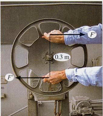
 Mechanical Systems Engineering_2016 Engineering Mechanics Statics 6. Moment of a Couple Dr. Rami Zakaria Moment of a Couple We need a moment (or torque) of (12 N m) to rotate the wheel. Notice that one
EQUIVALENT SYSTEMS, RESULTANTS OF FORCE AND COUPLE SYSTEM, & FURTHER REDUCTION OF A FORCE AND COUPLE SYSTEM
 EQUIVALENT SYSTEMS, RESULTANTS OF FORCE AND COUPLE SYSTEM, & FURTHER REDUCTION OF A FORCE AND COUPLE SYSTEM Today s Objectives: Students will be able to: a) Determine the effect of moving a force. b) Find
Torque. Physics 6A. Prepared by Vince Zaccone For Campus Learning Assistance Services at UCSB
 Physics 6A Torque is what causes angular acceleration (just like a force causes linear acceleration) Torque is what causes angular acceleration (just like a force causes linear acceleration) For a torque
Application of Forces. Chapter Eight. Torque. Force vs. Torque. Torque, cont. Direction of Torque 4/7/2015
 Raymond A. Serway Chris Vuille Chapter Eight Rotational Equilibrium and Rotational Dynamics Application of Forces The point of application of a force is important This was ignored in treating objects as
Unit 1. (a) tan α = (b) tan α = (c) tan α = (d) tan α =
 tan α = (b) tan α = (c) tan α = (d) tan α =") Unit 1 1. The subjects Engineering Mechanics deals with (a) Static (b) kinematics (c) Kinetics (d) All of the above 2. If the resultant of two forces P and Q is acting at an angle α with P, then (a) tan
Unit 1 1. The subjects Engineering Mechanics deals with (a) Static (b) kinematics (c) Kinetics (d) All of the above 2. If the resultant of two forces P and Q is acting at an angle α with P, then (a) tan
h p://edugen.wileyplus.com/edugen/courses/crs1404/pc/c05/c2hlch... CHAPTER 5 MOMENTS 1 of 3 10-Sep-12 16:35
 Peter Christopher/Masterfile... 1 of 3 10-Sep-12 16:35 CHAPTER 5 MOMENTS Peter Christopher/Masterfile... 2 of 3 10-Sep-12 16:35 Peter Christopher/Masterfile In Chapter 4 we considered the forces that push
S in. S in 40 M s = (20.35)(30.0) M s = 611 in-lb clockwise = 2.12 m with a negative action. The moment about B is
(30.0) M s = 611 in-lb clockwise = 2.12 m with a negative action. The moment about B is") Problem 4.14 The moment eerted about point E b the weight is 299 in-lb. What moment does the weight eert about point S? S 30 13 in. 12 in. E 40 The ke is the geometr rom trigonometr, cos 40 = d 2 13 in,
Problem 4.14 The moment eerted about point E b the weight is 299 in-lb. What moment does the weight eert about point S? S 30 13 in. 12 in. E 40 The ke is the geometr rom trigonometr, cos 40 = d 2 13 in,
Section 13.4 The Cross Product
 Section 13.4 The Cross Product Multiplying Vectors 2 In this section we consider the more technical multiplication which can be defined on vectors in 3-space (but not vectors in 2-space). 1. Basic Definitions
Vector is a quantity which has both magnitude and direction. We will use the arrow to designate vectors.
 In this section, we will study the fundamental operations (addition, resolving vectors into components) of force vectors. Vector is a quantity which has both magnitude and direction. We will use the arrow
Section 1 Changes in Motion. Chapter 4. Preview. Objectives Force Force Diagrams
 Section 1 Changes in Motion Preview Objectives Force Force Diagrams Section 1 Changes in Motion Objectives Describe how force affects the motion of an object. Interpret and construct free body diagrams.
SOLUTION 4 1. If A, B, and D are given vectors, prove the distributive law for the vector cross product, i.e., A : (B + D) = (A : B) + (A : D).
 = (A : B) + (A : D).") 4 1. If A, B, and D are given vectors, prove the distributive law for the vector cross product, i.e., A : (B + D) = (A : B) + (A : D). Consider the three vectors; with A vertical. Note obd is perpendicular
4 1. If A, B, and D are given vectors, prove the distributive law for the vector cross product, i.e., A : (B + D) = (A : B) + (A : D). Consider the three vectors; with A vertical. Note obd is perpendicular
Rotational Equilibrium
 Rotational Equilibrium 6-1 Rotational Equilibrium INTRODUCTION Have you ever tried to pull a stubborn nail out of a board or develop your forearm muscles by lifting weights? Both these activities involve
Force Couple Systems = Replacement of a Force with an Equivalent Force and Moment (Moving a Force to Another Point)
") orce Couple Sstems = eplacement of a orce with an Equivalent orce and oment (oving a orce to Another Point) The force acting on a bod has two effects: The first one is the tendenc to push or pull the bod
orce Couple Sstems = eplacement of a orce with an Equivalent orce and oment (oving a orce to Another Point) The force acting on a bod has two effects: The first one is the tendenc to push or pull the bod
 For a general development of the theoretical aspects of mechanics, however, a more rigorous treatment is possible by using vector analysis. A vector may be denoted by drawing a short arrow above the letter
The Cross Product. In this section, we will learn about: Cross products of vectors and their applications.
 The Cross Product In this section, we will learn about: Cross products of vectors and their applications. THE CROSS PRODUCT The cross product a x b of two vectors a and b, unlike the dot product, is a
UNIT - I. Review of the three laws of motion and vector algebra
 UNIT - I Review of the three laws of motion and vector algebra In this course on Engineering Mechanics, we shall be learning about mechanical interaction between bodies. That is we will learn how different
Engineering Mechanics Statics
 Mechanical Systems Engineering- 2016 Engineering Mechanics Statics 2. Force Vectors; Operations on Vectors Dr. Rami Zakaria MECHANICS, UNITS, NUMERICAL CALCULATIONS & GENERAL PROCEDURE FOR ANALYSIS Today
Please Visit us at:
 IMPORTANT QUESTIONS WITH ANSWERS Q # 1. Differentiate among scalars and vectors. Scalars Vectors (i) The physical quantities that are completely (i) The physical quantities that are completely described
Equilibrium of a Rigid Body. Engineering Mechanics: Statics
 Equilibrium of a Rigid Body Engineering Mechanics: Statics Chapter Objectives Revising equations of equilibrium of a rigid body in 2D and 3D for the general case. To introduce the concept of the free-body
3.1 CONDITIONS FOR RIGID-BODY EQUILIBRIUM
 3.1 CONDITIONS FOR RIGID-BODY EQUILIBRIUM Consider rigid body fixed in the x, y and z reference and is either at rest or moves with reference at constant velocity Two types of forces that act on it, the
Force in Mechanical Systems. Overview
 Force in Mechanical Systems Overview Force in Mechanical Systems What is a force? Created by a push/pull How is a force transmitted? For example by: Chains and sprockets Belts and wheels Spur gears Rods
Chapter 8. Rotational Equilibrium and Rotational Dynamics
 Chapter 8 Rotational Equilibrium and Rotational Dynamics 1 Force vs. Torque Forces cause accelerations Torques cause angular accelerations Force and torque are related 2 Torque The door is free to rotate
2-9. The plate is subjected to the forces acting on members A and B as shown. If θ = 60 o, determine the magnitude of the resultant of these forces
 2-9. The plate is subjected to the forces acting on members A and B as shown. If θ 60 o, determine the magnitude of the resultant of these forces and its direction measured clockwise from the positie x
Introduction. 1.1 Introduction. 1.2 Trigonometrical definitions
 Introduction 1.1 Introduction Stress analysis is an important part of engineering science, as failure of most engineering components is usually due to stress. The component under a stress investigation
Rotational Kinematics and Dynamics. UCVTS AIT Physics
 Rotational Kinematics and Dynamics UCVTS AIT Physics Angular Position Axis of rotation is the center of the disc Choose a fixed reference line Point P is at a fixed distance r from the origin Angular Position,
Assignment No. 1 RESULTANT OF COPLANAR FORCES
 Assignment No. 1 RESULTANT OF COPLANAR FORCES Theory Questions: 1) Define force and body. (Dec. 2004 2 Mks) 2) State and explain the law of transmissibility of forces. (May 2009 4 Mks) Or 3) What is law
STATICS. Bodies. Vector Mechanics for Engineers: Statics VECTOR MECHANICS FOR ENGINEERS: Design of a support
 4 Equilibrium CHAPTER VECTOR MECHANICS FOR ENGINEERS: STATICS Ferdinand P. Beer E. Russell Johnston, Jr. Lecture Notes: J. Walt Oler Texas Tech University of Rigid Bodies 2010 The McGraw-Hill Companies,
Appendix. Vectors, Systems of Equations
 ppendix Vectors, Systems of Equations Vectors, Systems of Equations.1.1 Vectors Scalar physical quantities (e.g., time, mass, density) possess only magnitude. Vectors are physical quantities (e.g., force,
Sports biomechanics explores the relationship between the body motion, internal forces and external forces to optimize the sport performance.
 What is biomechanics? Biomechanics is the field of study that makes use of the laws of physics and engineering concepts to describe motion of body segments, and the internal and external forces, which
Engineering Mechanics: Statics in SI Units, 12e
 Engineering Mechanics: Statics in SI Units, 12e 2 Force Vectors 1 Chapter Objectives Parallelogram Law Cartesian vector form Dot product and an angle between two vectors 2 Chapter Outline 1. Scalars and
ARCH 331 Note Set 3.1 Su2016abn. Forces and Vectors
 orces and Vectors Notation: = name for force vectors, as is A, B, C, T and P = force component in the direction = force component in the direction R = name for resultant vectors R = resultant component
Chapter 2: Force Vectors
 Chapter 2: Force Vectors Chapter Objectives To show how to add forces and resolve them into components using the Parallelogram Law. To express force and position in Cartesian vector form and explain how
Where, m = slope of line = constant c = Intercept on y axis = effort required to start the machine
 (ISO/IEC - 700-005 Certified) Model Answer: Summer 07 Code: 70 Important Instructions to examiners: ) The answers should be examined by key words and not as word-to-word as given in the model answer scheme.
If the pull is downward (Fig. 1), we want C to point into the page. If the pull is upward (Fig. 2), we want C to point out of the page.
, we want C to point into the page. If the pull is upward (Fig. 2), we want C to point out of the page.") 11.5 Cross Product Contemporary Calculus 1 11.5 CROSS PRODUCT This section is the final one about the arithmetic of vectors, and it introduces a second type of vector vector multiplication called the cross
11.5 Cross Product Contemporary Calculus 1 11.5 CROSS PRODUCT This section is the final one about the arithmetic of vectors, and it introduces a second type of vector vector multiplication called the cross
EQUATIONS OF EQUILIBRIUM & TWO-AND THREE-FORCE MEMEBERS
 EQUATIONS OF EQUILIBRIUM & TWO-AND THREE-FORCE MEMEBERS Today s Objectives: Students will be able to: a) Apply equations of equilibrium to solve for unknowns, and, b) Recognize two-force members. READING
MOMENT OF A FORCE SCALAR FORMULATION, CROSS PRODUCT, MOMENT OF A FORCE VECTOR FORMULATION, & PRINCIPLE OF MOMENTS
 MOMENT OF A FORCE SCALAR FORMULATION, CROSS PRODUCT, MOMENT OF A FORCE VECTOR FORMULATION, & PRINCIPLE OF MOMENTS Today s Objectives : Students will be able to: a) understand and define moment, and, b)
6. Vectors. Given two points, P 0 = (x 0, y 0 ) and P 1 = (x 1, y 1 ), a vector can be drawn with its foot at P 0 and
 and P 1 = (x 1, y 1 ), a vector can be drawn with its foot at P 0 and") 6. Vectors For purposes of applications in calculus and physics, a vector has both a direction and a magnitude (length), and is usually represented as an arrow. The start of the arrow is the vector s foot,
6. Vectors For purposes of applications in calculus and physics, a vector has both a direction and a magnitude (length), and is usually represented as an arrow. The start of the arrow is the vector s foot,
Chapter 12: Rotation of Rigid Bodies. Center of Mass Moment of Inertia Torque Angular Momentum Rolling Statics
 Chapter 12: Rotation of Rigid Bodies Center of Mass Moment of Inertia Torque Angular Momentum Rolling Statics Translational vs Rotational 2 / / 1/ 2 m x v dx dt a dv dt F ma p mv KE mv Work Fd P Fv 2 /
Model Answers Attempt any TEN of the following :
 (ISO/IEC - 70-005 Certified) Model Answer: Winter 7 Sub. Code: 17 Important Instructions to Examiners: 1) The answers should be examined by key words and not as word-to-word as given in the model answer
Three-Dimensional Coordinate Systems. Three-Dimensional Coordinate Systems. Three-Dimensional Coordinate Systems. Three-Dimensional Coordinate Systems
 To locate a point in a plane, two numbers are necessary. We know that any point in the plane can be represented as an ordered pair (a, b) of real numbers, where a is the x-coordinate and b is the y-coordinate.
Chapter 19 Angular Momentum
 Chapter 19 Angular Momentum Chapter 19 Angular Momentum... 2 19.1 Introduction... 2 19.2 Angular Momentum about a Point for a Particle... 3 19.2.1 Angular Momentum for a Point Particle... 3 19.2.2 Right-Hand-Rule
STATICS. FE Review. Statics, Fourteenth Edition R.C. Hibbeler. Copyright 2016 by Pearson Education, Inc. All rights reserved.
 STATICS FE Review 1. Resultants of force systems VECTOR OPERATIONS (Section 2.2) Scalar Multiplication and Division VECTOR ADDITION USING EITHER THE PARALLELOGRAM LAW OR TRIANGLE Parallelogram Law: Triangle
Moments and Torques. M = F d
 Moments and Torques When a force is applied to an object, the object reacts in six possible ways. It can elongate, compress, translate (moves left, right, up, down, etc.), bend, twist or rotate. The study
Miscellaneous (dimension, angle, etc.) - black [pencil] Use different colors in diagrams. Body outline - blue [black] Vector
![Miscellaneous (dimension, angle, etc.) - black [pencil] Use different colors in diagrams. Body outline - blue [black] Vector](/thumbs/80/82415275.jpg "Miscellaneous (dimension, angle, etc.) - black [pencil] Use different colors in diagrams. Body outline - blue [black] Vector") 1. Sstems of orces & s 2142111 Statics, 2011/2 Department of Mechanical Engineering, Chulalongkorn Uniersit bjecties Students must be able to Course bjectie Analze a sstem of forces and moments Chapter
1. Sstems of orces & s 2142111 Statics, 2011/2 Department of Mechanical Engineering, Chulalongkorn Uniersit bjecties Students must be able to Course bjectie Analze a sstem of forces and moments Chapter
Chapter 2 - Vector Algebra
 A spatial vector, or simply vector, is a concept characterized by a magnitude and a direction, and which sums with other vectors according to the Parallelogram Law. A vector can be thought of as an arrow
Chap. 4 Force System Resultants
 Chap. 4 Force System Resultants Chapter Outline Moment of a Force Scalar Formation Cross Product Moment of Force Vector Formulation Principle of Moments Moment of a Force about a Specified xis Moment of
Figure 17.1 The center of mass of a thrown rigid rod follows a parabolic trajectory while the rod rotates about the center of mass.
 17.1 Introduction A body is called a rigid body if the distance between any two points in the body does not change in time. Rigid bodies, unlike point masses, can have forces applied at different points
ARC241 Structural Analysis I Lecture 1, Sections ST1.1 ST2.4
 Lecture 1, Sections ST1.1 ST2.4 ST1.1-ST1.2) Introduction ST1.3) Units of Measurements ST1.4) The International System (SI) of Units ST1.5) Numerical Calculations ST1.6) General Procedure of Analysis ST2.1)
Static Equilibrium. Lecture 24. Chapter 12. Physics I. Department of Physics and Applied Physics
 Lecture 24 Chapter 12 Physics I Static Equilibrium Course website: http://faculty.uml.edu/andriy_danylov/teaching/physicsi IN THIS CHAPTER, you will discuss static equilibrium of an object Today we are
STATICS. Rigid Bodies: Equivalent Systems of Forces VECTOR MECHANICS FOR ENGINEERS: Eighth Edition CHAPTER. Ferdinand P. Beer E. Russell Johnston, Jr.
 Eighth E CHAPTER VECTOR MECHANICS FOR ENGINEERS: STATICS Ferdinand P. Beer E. Russell Johnston, Jr. Lecture Notes: J. Walt Oler Texas Tech University Rigid Bodies: Equivalent Systems of Forces Contents
P12 Torque Notes.notebook. March 26, Torques
 Torques The size of a torque depends on two things: 1. The size of the force being applied (a larger force will have a greater effect) 2. The distance away from the pivot point (the further away from this
RELATIVE MOTION ANALYSIS: VELOCITY (Section 16.5)
") RELATIVE MOTION ANALYSIS: VELOCITY (Section 16.5) Today s Objectives: Students will be able to: a) Describe the velocity of a rigid body in terms of translation and rotation components. b) Perform a relative-motion
RELATIVE MOTION ANALYSIS: VELOCITY (Section 16.5) Today s Objectives: Students will be able to: a) Describe the velocity of a rigid body in terms of translation and rotation components. b) Perform a relative-motion
STATICS. Bodies VECTOR MECHANICS FOR ENGINEERS: Ninth Edition CHAPTER. Ferdinand P. Beer E. Russell Johnston, Jr.
 N E 4 Equilibrium CHAPTER VECTOR MECHANICS FOR ENGINEERS: STATICS Ferdinand P. Beer E. Russell Johnston, Jr. Lecture Notes: J. Walt Oler Texas Tech University of Rigid Bodies 2010 The McGraw-Hill Companies,
Chapter 8. Centripetal Force and The Law of Gravity
 Chapter 8 Centripetal Force and The Law of Gravity Centripetal Acceleration An object traveling in a circle, even though it moves with a constant speed, will have an acceleration The centripetal acceleration
Vector components and motion
 Vector components and motion Objectives Distinguish between vectors and scalars and give examples of each. Use vector diagrams to interpret the relationships among vector quantities such as force and acceleration.
STATICS. Equivalent Systems of Forces. Vector Mechanics for Engineers: Statics VECTOR MECHANICS FOR ENGINEERS: Contents & Objectives.
 3 Rigid CHATER VECTOR ECHANICS FOR ENGINEERS: STATICS Ferdinand. Beer E. Russell Johnston, Jr. Lecture Notes: J. Walt Oler Teas Tech Universit Bodies: Equivalent Sstems of Forces Contents & Objectives
CE 201 Statics. 2 Physical Sciences. Rigid-Body Deformable-Body Fluid Mechanics Mechanics Mechanics
 CE 201 Statics 2 Physical Sciences Branch of physical sciences 16 concerned with the state of Mechanics rest motion of bodies that are subjected to the action of forces Rigid-Body Deformable-Body Fluid
Chapter 4. Table of Contents. Section 1 Changes in Motion. Section 2 Newton's First Law. Section 3 Newton's Second and Third Laws
 Forces and the Laws of Motion Table of Contents Section 1 Changes in Motion Section 2 Newton's First Law Section 3 Newton's Second and Third Laws Section 4 Everyday Forces Section 1 Changes in Motion Objectives
UNIT-V MOMENT DISTRIBUTION METHOD
 UNIT-V MOMENT DISTRIBUTION METHOD Distribution and carryover of moments Stiffness and carry over factors Analysis of continuous beams Plane rigid frames with and without sway Neylor s simplification. Hardy