Miscellaneous (dimension, angle, etc.) - black [pencil] Use different colors in diagrams. Body outline - blue [black] Vector
|
|
|
- Magdalene Barnett
- 5 years ago
- Views:
Transcription
 in scalar & ector forms")
1 1. Sstems of orces & s Statics, 2011/2 Department of Mechanical Engineering, Chulalongkorn Uniersit bjecties Students must be able to Course bjectie Analze a sstem of forces and moments Chapter bjecties Describe the characteristics and properties of forces and moments Determine and manipulate 2D/3D forces and moments (about a point, a line and couple) in scalar & ector forms Determine the resultant of forces & couples and find an equialent sstem at another position educe a 2D resultant to a single force or couple sstem and reduce a 3D resultant to a wrench 2 Contents Manipulation Quantities (Position, orce, ) orce Sstem esultants Equialent orce Sstems Use different colors in diagrams Bod outline - blue [black] Load - red Miscellaneous (dimension, angle, etc.) - black [pencil] Maths #1 Sine Law/Cosine Law A B C = = sin α sin β sin γ 2 2 C = A + B 2ABcos γ 3 4 1
2 peration #1 Unit aa = ( a ) A A = Ae, e = unit ector of A 5 peration #2 ight-handed coordinate sstem Dot Product A B = AB θ = A B + A B + A B cos z z 6 peration #3 ight-handed coordinate sstem Cross Product A B = ( ABsin θ ) e C 7 Phsical Quantit s representing phsical quantities can be classified ied Its action is associated with a unique point of application Described b magnitude, direction & point of application Sliding Has a unique like of action in space but not a unique point of application Described b magnitude, direction & line of action ree Its action is not confined or associated with a unique line in space Described b magnitude & direction 8 2
.")
3 Position Position r = = + + A ra Ai A j Azk r = = + + B rb Bi B j Bzk r = r r AB B A Coordinates s Position s orce orce Definition orce is a ector quantit. Staticall, force is the action of one bod on another. In dnamics, force is an action that tends to cause acceleration of an object. The SI unit of force magnitude is the Newton (N). ne Newton is equialent to one kilogram-meter per second squared (kg m/s 2 or kg m s 2 ) Eamples of mechanical force include the thrust of a rocket engine, the impetus that causes a car to speed up when ou step on the accelerator, and the pull of grait on our bod. orce can result from the action of electric fields, magnetic fields, and arious other phenomena orce orce eal-life Eamples & Phsical Meanings orce Classification Eternal s. Internal Surface/Contact s. Bod Applied s. eactie (Action s. eaction) Concentrated s. Distributed Internal orce Cables & Springs θ k = spring constant T T s Cable in tension = ks


4 orce orce orce epresentation quantit Magnitude Direction Point of application 10 N igid Bod A bod is considered rigid when the change in distance between an two points is negligible. igid s. Deformable bodies In Statics, bodies are considered rigid unless stated otherwise orce orce Graphical epresentation of tension and compression orce on igid Bod #1 orce on rigid bod Magnitude Direction Line of action orce on igid Bod #2 The force ma be applied at an point on its gien line of action without altering the resultant effects of the force eternal to the rigid bod on which it acts. Principle of Transmissibilit
5 Components 2D = + = i+ j = cos θ, = sin θ tan θ = = Components 3D #1 Cartesian Components = i + j + zk e = e z = i + j + k Components 3D #2 2 2 p = + = i+ j p p e p = = i + j P P P = e + k p p z Components 3D #3 cos θ = cosθ = Eleated Angle Directional Cosine z cos θ z =
6 Components 3D #4 Directional Cosine = = = cos cos cos θ θ θ z z cos θ + cos θ + cos θ = 1 z e = = e i+ e j+ e k z e = cos θ i+ cos θ j+ cos θ k z Eample Hibbeler E 2-8 #1 ind Cartesian components of force Eample Hibbeler E 2-8 #2 θ = α, θ = 60, θ = cos θ + cos θ + cos θ = cos α + cos 60 + cos 45 = 1 cos α =± 0.5 α z z cos ( 0.5) 120 or 60 1 = ± = rotate z about ais = cos θ + θ + θ i cos j cos zk = (200 N)cos60 i+ (200 N)cos60 j+ (200 N)cos 45 k = (100 i+ 100 j k) N = (100 i+ 100 j+ 141 k) N Ans orce Projection Along a Line Dot Product Angle between two ectors θ 1 A B = cos AB Components of a ector Scalar projection along a line a-a = + = cos θ = e = ( cos θ ) e = ( e ) e =
7 Eample Hibbeler E 2-17 #1 Determine the angle between the force and the pipe segment BA, and the magnitude of the component of the force (parallel and perpendicular) to BA. Eample Hibbeler E 2-17 #2 r = ( 2i 2j+ 1 k) ft BA r BA = 3 ft r ( 3 1 BC = j + k) ft r BC = 10 ft r ( ) ft ( 3 1 BA rbc i j + k j + k) ft cos θ = = = rba rbc (3 ft)( 10 ft) θ = = 42.5 Ans r ( 3 1 BC j + k) ft = = (80 lb) = ( j k ) lb r 10 ft BC Eample Hibbeler E 2-17 #3 r ( ) ft BA i j + k e BA = = = i j + k 3 ft BA ( lb) ( BA = eba = j + k i j + k) = lb = 59.0 lb Ans BA r = = lb = 54.0 lb Ans 2 2 BA Eample Hibbeler E 2-17 #4 BA = cos θ = (80 lb)cos = lb = 59.0 lb Ans = sin θ = (80 lb)sin = lb = 54.0 lb Ans


, = + P 1 1 2 2 = 1+ 2 = 1+ P + 2")
8 orce Parallelogram Summation Concurrent orces # Principle of Transmissibilit Lines of Action 29 orce Summation Concurrent orces #2 Triangular Law = Principle of Transmissibilit = 30 orce Summation Concurrent orces #3 Beware of incoming danger! 31 orce Summation Parallel orces #1 Cancellation irst Method Cancellation of Components 1 2 ind P such that = + ( P), = + P = 1+ 2 = 1+ P + 2 P = P 1 2 P


9 orce Summation Parallel orces #2 Cancellation irst Method: Cancellation of Components ind P such that = + ( P), = + P = 1+ 2 = 1+ P + 2 P = P P orce Summation Parallel orces #3 Second Method: Equialent 1 = a a Equialent about ais aa - = = + = orce Eample Hibbeler E 2-6 #1 Determine the magnitude and direction of the resultant force. 35 orce Eample Hibbeler E 2-6 #2 = (600cos30 i+ 600sin30 j) N = ( 400 sin 45 i+ 400cos 45 j) N
10 orce Eample Hibbeler E 2-6 #3 sstem II = sstem I = (600cos30 600sin30 ) N ( 400sin45 400cos45 = i + j + i + j) N = ( i j) N = + = ( N) + ( N) θ = θ = tan = N = 629 N Ans 1 tan ( ) 1 ( N N) θ = = 67.9 Ans 37 orce Eample Hibbeler E 2-6 #4 Scalar =, sstem II, sstem I = cos30 sin = (600 N)cos30 (400 N)sin45 = N =, sstem II, sstem I = sin30 + cos = (600 N)sin30 + (400 N)cos45 = N = ( N) ( N) = N = 629 N Ans θ = tan ( ) θ = tan ( N N) θ = = 67.9 Ans 2 38 orce orce Eample Hibbeler E 2-9 #1 Eample Hibbeler E 2-9 #2 Determine the magnitude and the coordinate direction angles of the resultant force acting on the ring
11 orce Eample Hibbeler E 2-9 #3 sstem II = sstem I = (60 80 ) lb ( = j + k + i j + k) lb = (50i 40j+ 180 k) lb (50 lb) ( 40 lb) (180 lb) lb 191 lb Ans = + + = = orce Eample Hibbeler E 2-9 #4 e = = (50 i 40 j+ 180 k) lb ( lb) = i j k cos θ = e = θ = 74.8 cos θ = e = θ = 102 cos θ = e = θ = 19.6 Ans z z z orce orce Eample Hibbeler E 2-11 #1 Specif the coordinate direction angles of 2 so that the resultant acts along the positie ais and has a magnitude of 800 N. Eample Hibbeler E 2-11 #2 1 = 1cos θ + θ + θ 1i 1cos 1j 1cos z1k = (300 N)cos 45 i+ (300 N)cos60 j+ (300 N)cos120 k = ( i+ 150 j 150 k) N = i+ j + k z
 i+ (150 N + ) j + ( 150 N + ) k 2 2 2 z orce Eample Hibbeler E 2-11 #4 dir: 0 = 212.13 N + dir: 800 = 150 N + 2 z dir: 0 = 150 N + = 212 N = 650 N = 150 N Ans 2 2 z 2 2 2 z z dir: 212.")

12 orce Eample Hibbeler E 2-11 #3 (800 = j) N sstem II = sstem I = (800 j N) = ( i+ 150 j 150 k) N + ( 2i + 2j + 2zk) N (800 j N) = ( N + ) i+ (150 N + ) j + ( 150 N + ) k z orce Eample Hibbeler E 2-11 #4 dir: 0 = N + dir: 800 = 150 N + 2 z dir: 0 = 150 N + = 212 N = 650 N = 150 N Ans 2 2 z z z dir: N = (700 N)cos α α = dir: 650 N = (700 N)cos β β = dir: 0 = (700 N)cos γ γ = 77.6 Ans orce Eample Hibbeler E 2-15 #1 The roof is supported b cables as shown. If the cables eert forces AB = 100 N and AC = 120 N on the wall hook at A as shown, determine the magnitude of the resultant force acting at A. orce Eample Hibbeler E 2-15 #2 r (4 0) (0 0) (0 4) m (4 4 AB = i j k + + = i k) m rab = rab + rab = (4 m) + ( 4 m) = m r (4 4 AB i k) m AB = AB ( ) = (100 N) r AB m = ( i k) N AB r (4 2 4 AC = i + j k) m, rac = 6 m r AC AC = AC ( ) r AC ( AC = i + j k) N
 N = (150.711 N) + (40 N) + (150.711 N) 2 2 2 = 216.86 N = 217 N Ans 49 50 orce esolution #1 A ector ma be resoled into two components.")
13 orce Eample Hibbeler E 2-15 #3 orce Eample Hibbeler E 2-15 #4 sstem II = sstem I = + AB AC ( ) N ( = i k + i + j k) N = ( i+ 40 j k) N = ( N) + (40 N) + ( N) = N = 217 N Ans orce esolution #1 A ector ma be resoled into two components. = A+ B orce esolution #


14 d Definition #1 M is the tendenc of force to rotate a bod about an ais. M = d Definition #2 M is the tendenc of force to rotate a bod about an ais. z z ( M ) z ( M ) d Definition #3 is a ector quantit. Magnitude Direction Ais of otation The unit of moment is N m The moment-arm d The right-hand rule determined b ector cross product Positie sign conention: 2D +k (CCW), 3D +e aes of a force or torque Cross Product z k = i j + ĵ k i j k A B = A A A B B B z z A B = ( AB ) ( ) ( ) z AB z i AB z AB z j+ AB AB k î ĵ î
i ( r z rz ) j + ( r r )k r")

15 j r k rz z About a Point #2 i M = r = r About a Point #1 58 Cartesian ormulae 57 Cartesian ormulae M = r = (r z rz )i ( r z rz ) j + ( r r )k r magnitude r A r d 59 M = ra = rb = rc 60 Principle of Transmissibilit M moment ais M = r sin θ = d About a Point #4 M = r A M moment ais About a Point #3 15
16 About a Point #5 Verignon Theorem 1 The moment of a force about an point is equal to the sum of the moments of the components of the force about the same point. 2 r = M = r 1 + r 2 = r ( 1+ 2) = r 61 Eample Hibbeler E 4-4 #1 Determine the moment about the support at A. 62 Eample Hibbeler E 4-4 #2 r (1 3 2 B = i + j + k) m r (3 4 C = i + j) m r = r r = ( 2i 1j+ 2 k) m CB B C r = + CB ( 2i 1j 2 k) m, rcb = 3 m r + CB ( 2i 1j 2 k) m 1 u = = = ( i j k) r CB 3 m 3 = (60 N) u = ( 40 i 20 j+ 40 k) N 63 Eample Hibbeler E 4-4 #3 i j k M = = 3 m 4 m 0 m = ( A rc i j k) N m 40 N 20 N 40 N M A = (160 N) + ( 120 N) + (100 N) = N = 224 N m Ans 64 16
17 Eample Hibbeler E 4-4 #4 MA = rc = rb i j k M = = 1 m 3 m 2 m = ( A rb i j k) N m 40 N 20 N 40 N Eample Hibbeler E 4-7 #1 Determine the moment of the force about point Eample Hibbeler E 4-7 #2 r = (400 sin30 i 400cos30 j) N = (200 i j) N r = (0.4 i 0.2 j) m i j k M = r = 0.4 m 0.2 m 0 m 200 N N 0 N M = k N m M = 98.6 k N m Ans 67 Eample Hibbeler E 4-7 #3 Scalar M = + M M = (400 N)sin 30(0.2 m) (400 N)cos 30(0.4 m) M = 40 N m N m = N m Ans 68 17
18 About an Ais #1 M a = ea ( r ) M = M e = e ( r ) e a a a a a Eample Hibbeler E 4-8 #1 Determine the moments of this force about the and a aes. B r = + + A ( 3i 4j 6 k) m M = i ( ra ) i j k M = 3 m 4 m 6 m 40 N 20 N 10 N M = + i ( 80 i 210 j 100 k) N m M = 80 N m M = Mi = 80 i N m Ans Eample Hibbeler E 4-8 #2 M r = + B ( 3i 4 j) m, rb = 5 m 3 4 u = = ( + a rb rb i j) 5 5 M = a ua ( ra ) a 3 4 = ( i + j) ( 80 i 210 j k) N m N m M a = 3 4 M = = ( 120 N m)( + ) = (72 96 a Maua i j i j) N m Ans 5 5 B 71 Eample Hibbeler E 4-9 #1 Determine the moment M AB produced b = ( 600i + 200j 300k) N, which tends to rotate the rod about the AB ais i
 AB B r is directed from an point on the AB ais to an point on the line of action of the force. Eample Hibbeler E 4-9 #3 MA = rad M = (0.")
19 Eample Hibbeler E 4-9 #2 ( ) m, 0.2 m rb = i + j rb = r ( B i j) m u = = B r B 0.2 m u B = i j M = u ( r ) AB B r is directed from an point on the AB ais to an point on the line of action of the force. Eample Hibbeler E 4-9 #3 MA = rad M = (0.2 m) ( A j i j k) N M = ( 60i+ 120 k) N m A Tr point A MAB = MA ub M = ( AB i k N m) M = ( AB i j) M = N m AB M = M u M A AB B AB B = ( 48.0 i 24.0 j) N m Ans Eample Hibbeler E 4-9 #4 Tr point B tr r = (0.2 i 0.2 j+ 0.3 k) m BC r BC M = AB ub ( rb C ) M = + AB ( i j) M = + AB (0.2 i 0.2 j 0.3 k) m M = ( AB i j k) N M = ( A B i j) M = ( A B j k) N m M = N m A B Couple


20 Couple Definition #1 M = d = 0 The two forces that are equal, opposite, and colinear is called a couple. Couple is a ector Magnitude. Direction. of a couple is constant regardless of moment ais. Couple Definition #2 M = ra ( ) + rb = ( ra + rb) M = r AB A couple moment is a free ector A couple can act at an point since M depends onl upon the position ector r directed between the forces Couple Summation M = M1 + M2 M = ( r ) M 2 M M 2 P M 1 M 1 Eample Hibbeler E 4-13 #1 eplace the two couples acting on the pipe column b a resultant couple moment. M1 = d = (150 N)(0.4 m) = 60 N m M = (60 i ) N m (125 N) C = Ce C = j k 5 5 ( C = j k) N M2 = rdc C = (0.3 i m) (100 j 75 k) N = (22.5 j + 30 k) N m
 N m Ans 1 2 81 Concepts #1 eiew s can be manipulated b scalar multiplication, addition, subtraction, dot product, cross product and mied triple product.")
21 Eample Hibbeler E 4-13 #2 M = M + M = (60 i j+ 30 k) N m Ans Concepts #1 eiew s can be manipulated b scalar multiplication, addition, subtraction, dot product, cross product and mied triple product. s representing can be classified into free, sliding and fied ectors. Position ectors describe the position of a point relatie to a reference point or the origin. Staticall, force is the action of one bod on another. In dnamics, force is an action that tends to cause acceleration of an object. To define a force on rigid bodies, the magnitude, direction and line of action are required. Thus, the principle of transmissibilit is applicable to forces on rigid bodies. 82 esultant Concepts #2 eiew To define a moment about a point, the magnitude, direction and the point are required. To define a moment about an ais, the magnitude, direction and the aes are required. To define a couple, the magnitude and direction are required. 83 esultant Definition The force-couple sstems or force sstems can be reduced to a single force and a single couple (together called resultant) that eert the same effects of Net force Tendenc to translate Net moment Tendenc to rotate Two force-couple sstems are equialent if their resultants are the same


22 esultant esultant orce Sstems #1 = = + sstem II sstem I 1 2 M,sstem II = M,sstem I M = MC + ( r1 1 ) + ( r2 2 ) =, =, M = M + M C esultant Eample Hibbeler E 4-14 #1 eplace the current sstem b an equialent resultant force and couple moment acting A esultant Eample Hibbeler E 4-14 #2 =,ss II,ss I cos θ = 100 N 400cos45 N cos θ = N =,ss II,ss I sin θ = 600 N 400sin45 N sin θ = N 87 esultant Eample Hibbeler E 4-14 #3 = ( cos θ) + ( sin θ) 2 2 = N = 962 N Ans tan θ θ = θ = tan 1 sin θ cos θ N N = = 247 Ans M = M + A,ss II A,ss I M M A A = (600 N)(0.4 m) (400 N)sin 45 (0.8 m) (400 N)cos 45 (0.3 m) = N m = 551 N m Ans 88 22
 u CB = (300 N)( rcb rcb ) = ( 249.62 i+ 166.")
 N ( 249.62 166.")
 ( 800 = j + k + k k N) + M ( 0.15 0.1 ) m ( 249.62 166.41 = i + j + k i + j) N M = ( 400 j+ 300 k) N m + (0) N m + M = ( 166.41 249.62 j + 0.")
23 esultant esultant Eample Hibbeler E 4-15 #1 eplace the current sstem b an equialent resultant force and couple moment acting at its base (point ). Sstem I r r = + CB 0.15 i 0.1 j m CB = m 1 = 800 k N 2 = (300 N) u CB = (300 N)( rcb rcb ) = ( i j) N 4 3 M = Mu = (500) N m( + M j k) 5 5 = ( 400 j k) N m Eample Hibbeler E 4-15 #2 ss II = ss I = = ( 800 k) N + ( i j) N ( = i + j k) N = ( 250 i+ 166 j 800 k) N Ans Sstem II esultant Eample Hibbeler E 4-15 #3 M = M,ss II,ss I M = M + ( r 1) ( 2) C + rb M ( ) N m (1 m) ( 800 = j + k + k k N) + M ( ) m ( = i + j + k i + j) N M = ( 400 j+ 300 k) N m + (0) N m + M = ( j k) N m M = ( 166 i 650 j+ 300 k) N m Ans Equialent Sstem Equialent Sstem Definition Two force-couple sstems are equialent if the hae the same resultant. ( ) = ( ) ( M ) = ( M ) sstem I sstem II, sstem I, sstem II i
 i i i M 93 94 Equialent Sstem eduction Coplanar orce Sstems")

24 Equialent Sstem eduction Concurrent orce Sstems = Equialent Sstem eduction Coplanar orce Sstems #1 3 M 1 r 3 r 1 M 2 r = i M = M + ( r ) i i i M Equialent Sstem eduction Coplanar orce Sstems #2 M = d M d Equialent Sstem eduction Coplanar orce Sstems #3 A sstem of 2D forces and couples can be simplified to A sstem of a force through a point and a perpendicular couple A single resultant force


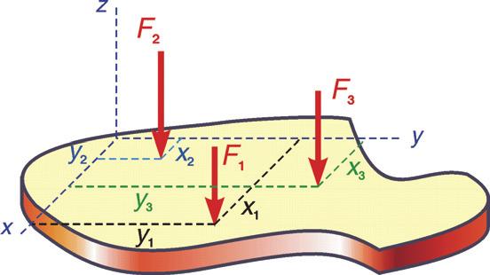
25 Equialent Sstem eduction Parallel orce Sstems #1 Equialent Sstem eduction Parallel orce Sstems #2 M 1 1 r 1 z r 2 r M 2 M z Equialent Sstem eduction Parallel orce Sstems #3 M z z d Equialent Sstem eduction Parallel orce Sstems #4 = = ( i i) = ( ) i i

 = 233.01 N = 420.47 N = 420 N 102 Equialent Sstem Eample Hibbeler E 4-16 #3 sin θ 233.01 N tan θ = = cos θ 350 N θ = 33.653 = 33.")

26 Equialent Sstem Eample Hibbeler E 4-16 #1 Determine the magnitude, direction and location on the beam of a resultant force which is equialent to the sstem of forces measured from E. 101 Equialent Sstem Eample Hibbeler E 4-16 #2,ss II =,ss I cos θ = (500 N)cos60 + (100 N) = 350 N,ss II =,ss I sin θ = (500 N)sin60 + (200 N) = N = N = 420 N 102 Equialent Sstem Eample Hibbeler E 4-16 #3 sin θ N tan θ = = cos θ 350 N θ = = 33.7 = 33.7 CW Ans ME,ss II = M E,ss I sin θ ( d) = (500 N)sin60 (4 m) (100 N)(0.5 m) (200 N)(2.5 m) ( N)( d) = N d = m = 5.07 m Ans 103 Equialent Sstem Eample Hibbeler E 4-19 #1 Determine the magnitude and direction of a resultant equialent to the gien force sstem and locate its point of application P on the coer plate. Sstem I Sstem II
 ft ss II = ss I A B C M = M = + + = 650 k lb Ans,ss II,ss I M = r + r A A B B M = (8 i")

 rom (1) = (2) ( 650 i+ 650 j) lb ft = (751.47 i+ 1551.5 j) lb ft Equating i and j components 1551.")
 M M M about & ( M + M )")
27 Equialent Sstem Eample Hibbeler E 4-19 #2 300 lb, 8 ft, 200 lb, 8 A = k ra = i B = k rb = j ft 150 lb, ( 8 sin 45 8cos 45 C = k rc = i + j) ft ss II = ss I A B C M = M = + + = 650 k lb Ans,ss II,ss I M = r + r A A B B M = (8 i ft) ( 300 k lb) + ( 8 j ft) ( 200 k lb) + M M M + r C = ( 8 sin 45 i+ 8cos 45 j) ft ( 150 k lb) = 2400 j i j lb ft = ( ) lb ft (1) C Equialent Sstem Eample Hibbeler E 4-19 #3 M = r = ( i + ) j ft ( 650 k lb) M = ( 650 i+ 650 j) lb ft (2) rom (1) = (2) ( 650 i+ 650 j) lb ft = ( i j) lb ft Equating i and j components lb ft = = ft = 2.39 ft Ans 650 lb = lb ft 650 lb = ft = 1.16 ft Ans Equialent Sstem eduction 3D Sstem to a Wrench #1 about & about & ( + ) M M M about & ( M + M ) about P & M Equialent Sstem eduction 3D Sstem to a Wrench #2 about P & M about P & M about P (free ector) i j i


28 Equialent Sstem Sign Conention eduction 3D Sstem to a Wrench #3 Positie wrench screw Negatie wrench unscrew 109 Equialent Sstem eduction of orce Sstems A sstem of 2D forces and couples can be simplified to A sstem of a force through a point and a perpendicular couple A single resultant force or If there is no resultant force component, a single couple A sstem of 3D forces and couples can be simplified to A sstem of a force through a point and a couple A single wrench 110 Equialent Sstem Eample Hibbeler E #1 The three forces acting on the block each hae a magnitude of 10 N. eplace this sstem b a wrench and specif the point where the wrench intersects the z ais, measured from point. Equialent Sstem Eample Hibbeler E #2 = sstem I sstem II = (10 N)(cos 45 i sin45 j) (10 j N) + (10 N)( cos 45 i+ sin 45 j) = = 10 j N
29 Equialent Sstem Eample Hibbeler E #3 = 10 j N M = M j N m = M M,sstem I,sstem II ( r + + = + B 1) ( ra 2) ( ra 3 ) ( rd ) M j ( r 1) + ( 2 ) = ( ) + AB ra rd M j ( 2 k m) (10 N)(cos 45 i sin45 j) + (6 j+ 2 k) m ( 10 j N) = ( dk ) ( 10 j N) + ( M j N m) 113 Equialent Sstem Eample Hibbeler E #4 ( 10 2i 10 2j+ 20 i) N m = (10 N) di+ M j -direction: ( 10 2) N m = M M = 10 2 N m = N m -direction: ( ) N m = (10 N) d d = m Wrench: = 10 j N M = 14.1 j N m d = m Ans 114 Equialent Sstem eduction Summar General force sstems Single force + single couple 2D force sstems Single force or single couple simplest sstems 3D force sstems Wrench 115 Concepts #3 eiew Two force sstems are equialent if their resultants are the same. A force sstem or force-couple sstem can be reduced to the resultant (a single force and a single couple) that eert the same effects of net force and net moment. orce sstem reduction A 2D force sstem can be reduced to a single force or, in case of no net force, a single couple. A 3D force sstem can be reduced to a wrench
STATICS. Equivalent Systems of Forces. Vector Mechanics for Engineers: Statics VECTOR MECHANICS FOR ENGINEERS: Contents & Objectives.
 3 Rigid CHATER VECTOR ECHANICS FOR ENGINEERS: STATICS Ferdinand. Beer E. Russell Johnston, Jr. Lecture Notes: J. Walt Oler Teas Tech Universit Bodies: Equivalent Sstems of Forces Contents & Objectives
Force Couple Systems = Replacement of a Force with an Equivalent Force and Moment (Moving a Force to Another Point)
") orce Couple Sstems = eplacement of a orce with an Equivalent orce and oment (oving a orce to Another Point) The force acting on a bod has two effects: The first one is the tendenc to push or pull the bod
orce Couple Sstems = eplacement of a orce with an Equivalent orce and oment (oving a orce to Another Point) The force acting on a bod has two effects: The first one is the tendenc to push or pull the bod
2-9. The plate is subjected to the forces acting on members A and B as shown. If θ = 60 o, determine the magnitude of the resultant of these forces
 2-9. The plate is subjected to the forces acting on members A and B as shown. If θ 60 o, determine the magnitude of the resultant of these forces and its direction measured clockwise from the positie x
APPLIED MECHANICS I Resultant of Concurrent Forces Consider a body acted upon by co-planar forces as shown in Fig 1.1(a).
.") PPLIED MECHNICS I 1. Introduction to Mechanics Mechanics is a science that describes and predicts the conditions of rest or motion of bodies under the action of forces. It is divided into three parts 1.
PPLIED MECHNICS I 1. Introduction to Mechanics Mechanics is a science that describes and predicts the conditions of rest or motion of bodies under the action of forces. It is divided into three parts 1.
ARCH 614 Note Set 2 S2011abn. Forces and Vectors
 orces and Vectors Notation: = name for force vectors, as is A, B, C, T and P = force component in the direction = force component in the direction h = cable sag height L = span length = name for resultant
hwhat is mechanics? hscalars and vectors hforces are vectors htransmissibility of forces hresolution of colinear forces hmoments and couples
 orces and Moments CIEG-125 Introduction to Civil Engineering all 2005 Lecture 3 Outline hwhat is mechanics? hscalars and vectors horces are vectors htransmissibilit of forces hresolution of colinear forces
Course Overview. Statics (Freshman Fall) Dynamics: x(t)= f(f(t)) displacement as a function of time and applied force
 Dynamics: x(t)= f(f(t)) displacement as a function of time and applied force") Course Overview Statics (Freshman Fall) Engineering Mechanics Dynamics (Freshman Spring) Strength of Materials (Sophomore Fall) Mechanism Kinematics and Dynamics (Sophomore Spring ) Aircraft structures
Course Overview Statics (Freshman Fall) Engineering Mechanics Dynamics (Freshman Spring) Strength of Materials (Sophomore Fall) Mechanism Kinematics and Dynamics (Sophomore Spring ) Aircraft structures
MOMENT OF A COUPLE. Today s Objectives: Students will be able to a) define a couple, and, b) determine the moment of a couple.
 define a couple, and, b) determine the moment of a couple.") MOMENT OF A COUPLE Today s Objectives: Students will be able to a) define a couple, and, b) determine the moment of a couple. In Class activities: Check Homework Reading Quiz Applications Moment of a Couple
MOMENT OF A COUPLE Today s Objectives: Students will be able to a) define a couple, and, b) determine the moment of a couple. In Class activities: Check Homework Reading Quiz Applications Moment of a Couple
ARCH 331 Note Set 3.1 Su2016abn. Forces and Vectors
 orces and Vectors Notation: = name for force vectors, as is A, B, C, T and P = force component in the direction = force component in the direction R = name for resultant vectors R = resultant component
Force Couple Systems = Reduction of a Force to an Equivalent Force and Moment (Moving a Force to Another Point) acting on a body has two effects:
 acting on a body has two effects:") ESULTANTS orce Couple Systems = eduction of a orce to an Equivalent orce and Moment (Moving a orce to Another Point) The force acting on a body has two effects: the first one is the tendency to push or
ESULTANTS orce Couple Systems = eduction of a orce to an Equivalent orce and Moment (Moving a orce to Another Point) The force acting on a body has two effects: the first one is the tendency to push or
MOMENT OF A COUPLE. Today s Objectives: Students will be able to. a) define a couple, and, b) determine the moment of a couple.
 define a couple, and, b) determine the moment of a couple.") Today s Objectives: Students will be able to MOMENT OF A COUPLE a) define a couple, and, b) determine the moment of a couple. In-Class activities: Check Homework Reading Quiz Applications Moment of a Couple
Today s Objectives: Students will be able to MOMENT OF A COUPLE a) define a couple, and, b) determine the moment of a couple. In-Class activities: Check Homework Reading Quiz Applications Moment of a Couple
acting on a body has two effects:
 The force acting on a body has two effects: the first one is the tendency to push or pull the body in the direction of the force, and the second one is to rotate the body about any fixed axis which does
Determine the angle θ between the two position vectors.
 -100. Determine the angle θ between the two position vectors. -105. A force of 80 N is applied to the handle of the wrench. Determine the magnitudes of the components of the force acting along the axis
two forces and moments Structural Math Physics for Structures Structural Math
 RHITETURL STRUTURES: ORM, EHVIOR, ND DESIGN DR. NNE NIHOLS SUMMER 05 lecture two forces and moments orces & Moments rchitectural Structures 009abn Structural Math quantify environmental loads how big is
Equilibrium of Rigid Bodies
 Equilibrium of Rigid Bodies 1 2 Contents Introduction Free-Bod Diagram Reactions at Supports and Connections for a wo-dimensional Structure Equilibrium of a Rigid Bod in wo Dimensions Staticall Indeterminate
STATICS. Equivalent Systems of Forces. Vector Mechanics for Engineers: Statics VECTOR MECHANICS FOR ENGINEERS: Contents 9/3/2015.
 3 Rigid CHPTER VECTR ECHNICS R ENGINEERS: STTICS erdinand P. eer E. Russell Johnston, Jr. Lecture Notes: J. Walt ler Teas Tech Universit odies: Equivalent Sstems of orces Contents Introduction Eternal
Mechanics: Scalars and Vectors
 Mechanics: Scalars and Vectors Scalar Onl magnitude is associated with it Vector e.g., time, volume, densit, speed, energ, mass etc. Possess direction as well as magnitude Parallelogram law of addition
Ishik University / Sulaimani Architecture Department Structure ARCH 214 Chapter -4- Force System Resultant
 Ishik University / Sulaimani Architecture Department 1 Structure ARCH 214 Chapter -4- Force System Resultant 2 1 CHAPTER OBJECTIVES To discuss the concept of the moment of a force and show how to calculate
Engineering Mechanics: Statics in SI Units, 12e Force Vectors
 Engineering Mechanics: Statics in SI Units, 1e orce Vectors 1 Chapter Objectives Parallelogram Law Cartesian vector form Dot product and angle between vectors Chapter Outline 1. Scalars and Vectors. Vector
Tenth Edition STATICS 1 Ferdinand P. Beer E. Russell Johnston, Jr. David F. Mazurek Lecture Notes: John Chen California Polytechnic State University
 T E CHAPTER 1 VECTOR MECHANICS FOR ENGINEERS: STATICS Ferdinand P. Beer E. Russell Johnston, Jr. David F. Mazurek Lecture Notes: Introduction John Chen California Polytechnic State University! Contents
ENT 151 STATICS. Statics of Particles. Contents. Resultant of Two Forces. Introduction
 CHAPTER ENT 151 STATICS Lecture Notes: Azizul bin Mohamad KUKUM Statics of Particles Contents Introduction Resultant of Two Forces Vectors Addition of Vectors Resultant of Several Concurrent Forces Sample
SIMPLIFICATION OF FORCE AND COUPLE SYSTEMS & THEIR FURTHER SIMPLIFICATION
 SIMPLIFICATION OF FORCE AND COUPLE SYSTEMS & THEIR FURTHER SIMPLIFICATION Today s Objectives: Students will be able to: a) Determine the effect of moving a force. b) Find an equivalent force-couple system
STATICS. Statics of Particles VECTOR MECHANICS FOR ENGINEERS: Eighth Edition CHAPTER. Ferdinand P. Beer E. Russell Johnston, Jr.
 Eighth E CHAPTER VECTOR MECHANICS FOR ENGINEERS: STATICS Ferdinand P. Beer E. Russell Johnston, Jr. Statics of Particles Lecture Notes: J. Walt Oler Teas Tech Universit Contents Introduction Resultant
MOTION IN 2-DIMENSION (Projectile & Circular motion And Vectors)
") MOTION IN -DIMENSION (Projectile & Circular motion nd Vectors) INTRODUCTION The motion of an object is called two dimensional, if two of the three co-ordinates required to specif the position of the object
MOTION IN -DIMENSION (Projectile & Circular motion nd Vectors) INTRODUCTION The motion of an object is called two dimensional, if two of the three co-ordinates required to specif the position of the object
Chapter -4- Force System Resultant
 Ishik University / Sulaimani Civil Engineering Department Chapter -4- Force System Resultant 1 2 1 CHAPTER OBJECTIVES To discuss the concept of the moment of a force and show how to calculate it in two
POSITION VECTORS & FORCE VECTORS
 POSITION VECTORS & FORCE VECTORS Today s Objectives: Students will be able to : a) Represent a position vector in Cartesian coordinate form, from given geometry. b) Represent a force vector directed along
Chapter 5 Equilibrium of a Rigid Body Objectives
 Chapter 5 Equilibrium of a Rigid Bod Objectives Develop the equations of equilibrium for a rigid bod Concept of the free-bod diagram for a rigid bod Solve rigid-bod equilibrium problems using the equations
ME 141. Engineering Mechanics
 ME 141 Engineering Mechanics Lecture : Statics of particles Ahma Shahei Shakil Lecturer, Dept. of Mechanical Engg, BUET E-mail: sshakil@me.buet.ac.b, shakil6791@gmail.com Website: teacher.buet.ac.b/sshakil
EVALUATE: If the angle 40 is replaces by (cable B is vertical), then T = mg and
, then T = mg and") 58 IDENTIY: ppl Newton s 1st law to the wrecing ball Each cable eerts a force on the ball, directed along the cable SET UP: The force diagram for the wrecing ball is setched in igure 58 (a) T cos 40 mg
58 IDENTIY: ppl Newton s 1st law to the wrecing ball Each cable eerts a force on the ball, directed along the cable SET UP: The force diagram for the wrecing ball is setched in igure 58 (a) T cos 40 mg
MEM202 Engineering Mechanics - Statics MEM
 E Engineering echanics - Statics E hapter 6 Equilibrium of Rigid odies k j i k j i R z z r r r r r r r r z z E Engineering echanics - Statics Equilibrium of Rigid odies E Pin Support N w N/m 5 N m 6 m
Ishik University / Sulaimani Civil Engineering Department. Chapter -2-
 Ishik University / Sulaimani Civil Engineering Department Chapter -- 1 orce Vectors Contents : 1. Scalars and Vectors. Vector Operations 3. Vector Addition of orces 4. Addition of a System of Coplanar
CHAPTER 2. Copyright McGraw-Hill Education. Permission required for reproduction or display.
 CHAPTER 2 PROBLEM 2.1 Two forces are applied as shown to a hook. Determinee graphicall the magnitude and direction of their resultant using (a) the parallelogram law, (b) the triangle rule. (a) Parallelogram
EQUIVALENT SYSTEMS, RESULTANTS OF FORCE AND COUPLE SYSTEM, & FURTHER REDUCTION OF A FORCE AND COUPLE SYSTEM
 EQUIVALENT SYSTEMS, RESULTANTS OF FORCE AND COUPLE SYSTEM, & FURTHER REDUCTION OF A FORCE AND COUPLE SYSTEM Today s Objectives: Students will be able to: a) Determine the effect of moving a force. b) Find
27 ft 3 adequately describes the volume of a cube with side 3. ft F adequately describes the temperature of a person.
 VECTORS The stud of ectors is closel related to the stud of such phsical properties as force, motion, elocit, and other related topics. Vectors allow us to model certain characteristics of these phenomena
EQUATIONS OF EQUILIBRIUM & TWO-AND THREE-FORCE MEMEBERS
 EQUATIONS OF EQUILIBRIUM & TWO-AND THREE-FORCE MEMEBERS Today s Objectives: Students will be able to: a) Apply equations of equilibrium to solve for unknowns, and, b) Recognize two-force members. READING
Engineering Mechanics Statics
 Mechanical Systems Engineering_2016 Engineering Mechanics Statics 6. Moment of a Couple Dr. Rami Zakaria Moment of a Couple We need a moment (or torque) of (12 N m) to rotate the wheel. Notice that one
Trigonometry. Pythagorean Theorem. Force Components. Components of Force. hypotenuse. hypotenuse
 Pthagorean Theorem Trigonometr B C α A c α b a + b c a opposite side sin sinα hpotenuse adjacent side cos cosα hpotenuse opposite side tan tanα adjacent side AB CB CA CB AB AC orce Components Components
ARCH 631 Note Set 2.1 F2010abn. Statics Primer
 RCH 631 Note Set.1 F010abn Statics Primer Notation: a = name for acceleration = area (net = with holes, bearing = in contact, etc...) (C) = shorthand for compression d = perpendicular distance to a force
Moment of a force (scalar, vector ) Cross product Principle of Moments Couples Force and Couple Systems Simple Distributed Loading
 Cross product Principle of Moments Couples Force and Couple Systems Simple Distributed Loading") Chapter 4 Moment of a force (scalar, vector ) Cross product Principle of Moments Couples Force and Couple Systems Simple Distributed Loading The moment of a force about a point provides a measure of the
Chapter 4 Moment of a force (scalar, vector ) Cross product Principle of Moments Couples Force and Couple Systems Simple Distributed Loading The moment of a force about a point provides a measure of the
S in. S in 40 M s = (20.35)(30.0) M s = 611 in-lb clockwise = 2.12 m with a negative action. The moment about B is
(30.0) M s = 611 in-lb clockwise = 2.12 m with a negative action. The moment about B is") Problem 4.14 The moment eerted about point E b the weight is 299 in-lb. What moment does the weight eert about point S? S 30 13 in. 12 in. E 40 The ke is the geometr rom trigonometr, cos 40 = d 2 13 in,
Problem 4.14 The moment eerted about point E b the weight is 299 in-lb. What moment does the weight eert about point S? S 30 13 in. 12 in. E 40 The ke is the geometr rom trigonometr, cos 40 = d 2 13 in,
2.1 Scalars and Vectors
 2.1 Scalars and Vectors Scalar A quantity characterized by a positive or negative number Indicated by letters in italic such as A e.g. Mass, volume and length 2.1 Scalars and Vectors Vector A quantity
Force System Resultants. Engineering Mechanics: Statics
 Force System Resultants Engineering Mechanics: Statics Chapter Objectives To discuss the concept of the moment of a force and show how to calculate it in 2-D and 3-D systems. Definition of the moment of
Space Coordinates and Vectors in Space. Coordinates in Space
 0_110.qd 11//0 : PM Page 77 SECTION 11. Space Coordinates and Vectors in Space 77 -plane Section 11. -plane -plane The three-dimensional coordinate sstem Figure 11.1 Space Coordinates and Vectors in Space
Vector Mechanics: Statics
 PDHOnline Course G492 (4 PDH) Vector Mechanics: Statics Mark A. Strain, P.E. 2014 PDH Online PDH Center 5272 Meadow Estates Drive Fairfax, VA 22030-6658 Phone & Fax: 703-988-0088 www.pdhonline.org www.pdhcenter.com
DOT PRODUCT. Statics, Fourteenth Edition in SI Units R.C. Hibbeler. Copyright 2017 by Pearson Education, Ltd. All rights reserved.
 DOT PRODUCT Today s Objective: Students will be able to use the vector dot product to: a) determine an angle between two vectors and, b) determine the projection of a vector along a specified line. In-Class
Statics deal with the condition of equilibrium of bodies acted upon by forces.
 Mechanics It is defined as that branch of science, which describes and predicts the conditions of rest or motion of bodies under the action of forces. Engineering mechanics applies the principle of mechanics
Torque. Objectives. Assessment. Assessment. Equations. Physics terms 6/2/14
 Objectives Calculate torque given the lever arm (perpendicular distance) and the force. Calculate torque in newton meters and in pound feet. Interpret positive and negative signs in the context of torque.
five moments ELEMENTS OF ARCHITECTURAL STRUCTURES: FORM, BEHAVIOR, AND DESIGN DR. ANNE NICHOLS SPRING 2014 lecture ARCH 614
 ELEMENTS OF ARCHITECTURAL STRUCTURES: FORM, BEHAVIOR, AND DESIGN DR. ANNE NICHOLS SPRING 2014 lecture five moments Moments 1 Moments forces have the tendency to make a body rotate about an axis http://www.physics.umd.edu
Force in Mechanical Systems. Overview
 Force in Mechanical Systems Overview Force in Mechanical Systems What is a force? Created by a push/pull How is a force transmitted? For example by: Chains and sprockets Belts and wheels Spur gears Rods
Name. MECH 223 Engineering Statics. Midterm 1, February 24 th 2015
 1 Name MECH 223 Engineering Statics Midterm 1, February 24 th 2015 Question 1 (20 + 5 points) (a) (5 points) Form the vector products B C and B C (where B = B ) and use the result to prove the identity
Chapter 2: Statics of Particles
 CE297-A09-Ch2 Page 1 Wednesday, August 26, 2009 4:18 AM Chapter 2: Statics of Particles 2.1-2.3 orces as Vectors & Resultants orces are drawn as directed arrows. The length of the arrow represents the
Static Equilibrium. University of Arizona J. H. Burge
 Static Equilibrium Static Equilibrium Definition: When forces acting on an object which is at rest are balanced, then the object is in a state of static equilibrium. - No translations - No rotations In
Geometry review, part I
 Geometr reie, part I Geometr reie I Vectors and points points and ectors Geometric s. coordinate-based (algebraic) approach operations on ectors and points Lines implicit and parametric equations intersections,
Engineering Mechanics Statics
 Mechanical Systems Engineering- 2016 Engineering Mechanics Statics 2. Force Vectors; Operations on Vectors Dr. Rami Zakaria MECHANICS, UNITS, NUMERICAL CALCULATIONS & GENERAL PROCEDURE FOR ANALYSIS Today
Engineering Mechanics: Statics in SI Units, 12e
 Engineering Mechanics: Statics in SI Units, 12e 5 Equilibrium of a Rigid Body Chapter Objectives Develop the equations of equilibrium for a rigid body Concept of the free-body diagram for a rigid body
ENGINEERING MECHANICS BAA1113. Chapter 4: Force System Resultants (Static)
") ENGINEERING MECHANICS BAA1113 Chapter 4: Force System Resultants (Static) by Pn Rokiah Bt Othman Faculty of Civil Engineering & Earth Resources rokiah@ump.edu.my Chapter Description Aims To explain the
ENGINEERING MECHANICS BAA1113 Chapter 4: Force System Resultants (Static) by Pn Rokiah Bt Othman Faculty of Civil Engineering & Earth Resources rokiah@ump.edu.my Chapter Description Aims To explain the
Chapter Objectives. Copyright 2011 Pearson Education South Asia Pte Ltd
 Chapter Objectives To develop the equations of equilibrium for a rigid body. To introduce the concept of the free-body diagram for a rigid body. To show how to solve rigid-body equilibrium problems using
Chapter Objectives. Copyright 2011 Pearson Education South Asia Pte Ltd
 Chapter Objectives To show how to add forces and resolve them into components using the Parallelogram Law. To express force and position in Cartesian vector form and explain how to determine the vector
Sports biomechanics explores the relationship between the body motion, internal forces and external forces to optimize the sport performance.
 What is biomechanics? Biomechanics is the field of study that makes use of the laws of physics and engineering concepts to describe motion of body segments, and the internal and external forces, which
Physics 111. Applying Newton s Laws. Lecture 9 (Walker: 5.4-5) Newton s Third Law Free Body Diagram Solving 2-D Force Problems Weight & Gravity
 Newton s Third Law Free Body Diagram Solving 2-D Force Problems Weight & Gravity") Phsics 111 Lecture 9 (Walker: 5.4-5) Newton s Third Law ree Bod Diagram Solving -D orce Problems Weight & Gravit Sept. 1, 009 Quiz Wednesda - Chaps. 3 & 4 Lecture 9 1/6 Newton s Third Law of Motion orces
Phsics 111 Lecture 9 (Walker: 5.4-5) Newton s Third Law ree Bod Diagram Solving -D orce Problems Weight & Gravit Sept. 1, 009 Quiz Wednesda - Chaps. 3 & 4 Lecture 9 1/6 Newton s Third Law of Motion orces
PROBLEM 16.4 SOLUTION
 PROBLEM 16.4 The motion of the.5-kg rod AB is guided b two small wheels which roll freel in horizontal slots. If a force P of magnitude 8 N is applied at B, determine (a) the acceleration of the rod, (b)
APPLYING NEWTON S LAWS
 APPLYING NEWTON S LAWS 5 igible mass. Let T r be the tension in the rope and let T c be the tension in the chain. EXECUTE: (a) The free-bod diagram for each weight is the same and is given in Figure 5.1a.
STATICS. Vector Mechanics for Engineers: Statics VECTOR MECHANICS FOR ENGINEERS: Contents 9/3/2015
 6 Analsis CHAPTER VECTOR MECHANICS OR ENGINEERS: STATICS erdinand P. Beer E. Russell Johnston, Jr. of Structures Lecture Notes: J. Walt Oler Texas Tech Universit Contents Introduction Definition of a Truss
Chapter 2: Force Vectors
 Chapter 2: Force Vectors Chapter Objectives To show how to add forces and resolve them into components using the Parallelogram Law. To express force and position in Cartesian vector form and explain how
Engineering Mechanics I. Phongsaen PITAKWATCHARA
 2103-213 Engineering Mechanics I phongsaen@gmail.com December 6, 2007 Contents Preface iii 1 Introduction to Statics 1 1.0 Outline................................. 2 1.1 Basic Concepts............................
ARC241 Structural Analysis I Lecture 5, Sections ST4.5 ST4.10
 Lecture 5, Sections ST4.5 ST4.10 ST4.5) Moment of a Force about a Specified Axis ST4.6) Moment of a Couple ST4.7) Equivalent System ST4.8) Resultant of a Force and a Couple System ST4.9) Further Reduction
CHAPTER 1 MEASUREMENTS AND VECTORS
 CHPTER 1 MESUREMENTS ND VECTORS 1 CHPTER 1 MESUREMENTS ND VECTORS 1.1 UNITS ND STNDRDS n phsical quantit must have, besides its numerical value, a standard unit. It will be meaningless to sa that the distance
3.1 CONDITIONS FOR RIGID-BODY EQUILIBRIUM
 3.1 CONDITIONS FOR RIGID-BODY EQUILIBRIUM Consider rigid body fixed in the x, y and z reference and is either at rest or moves with reference at constant velocity Two types of forces that act on it, the
Introduction to Engineering Mechanics
 Introduction to Engineering Mechanics Statics October 2009 () Introduction 10/09 1 / 19 Engineering mechanics Engineering mechanics is the physical science that deals with the behavior of bodies under
5.3 Rigid Bodies in Three-Dimensional Force Systems
 5.3 Rigid odies in Three-imensional Force Sstems 5.3 Rigid odies in Three-imensional Force Sstems Eample 1, page 1 of 5 1. For the rigid frame shown, determine the reactions at the knife-edge supports,,.
Solution 11. Kinetics of rigid body(newton s Second Law)
") Solution () urpose and Requirement Solution Kinetics of rigid bod(newton s Second Law) In rob, kinematics stud regarding acceleration of mass center should be done before Newton s second law is used to
Solution () urpose and Requirement Solution Kinetics of rigid bod(newton s Second Law) In rob, kinematics stud regarding acceleration of mass center should be done before Newton s second law is used to
MECHANICS. Prepared by Engr. John Paul Timola
 MECHANICS Prepared by Engr. John Paul Timola MECHANICS a branch of the physical sciences that is concerned with the state of rest or motion of bodies that are subjected to the action of forces. subdivided
a Particle Forces the force. of action its sense is of application. Experimen demonstra forces ( P Resultant of Two Note: a) b) momentum)
 b) momentum)") Chapter 2 : Statics of a Particle 2.2 Force on a Particle: Resultant of Two Forces Recall, force is a vector quantity whichh has magnitude and direction. The direction of the the force. force is defined
Chapter 2 : Statics of a Particle 2.2 Force on a Particle: Resultant of Two Forces Recall, force is a vector quantity whichh has magnitude and direction. The direction of the the force. force is defined
EQUIVALENT SYSTEMS, RESULTANTS OF FORCE AND COUPLE SYSTEM, & FURTHER REDUCTION OF A FORCE AND COUPLE SYSTEM
 EQUIVALENT SYSTEMS, RESULTANTS OF FORCE AND COUPLE SYSTEM, & FURTHER REDUCTION OF A FORCE AND COUPLE SYSTEM Today s Objectives: Students will be able to: c) Determine the effect of moving a force. b) Find
EQUILIBRIUM OF RIGID BODIES
 EQUILIBRIUM OF RIGID BODIES Equilibrium A body in equilibrium is at rest or can translate with constant velocity F = 0 M = 0 EQUILIBRIUM IN TWO DIMENSIONS Case where the force system acting on a rigid
Worked Examples on Rectangular Components in Three-Dimensional Force Systems
 Worked Eamples on Rectangular Components in Three-Dimensional Force Sstems b Mark P. Rossow Southern Illinois Universit Edwardsville C 2005 b Mark P. Rossow Rectangular Components in Three-Dimensional
Eng Sample Test 4
 1. An adjustable tow bar connecting the tractor unit H with the landing gear J of a large aircraft is shown in the figure. Adjusting the height of the hook F at the end of the tow bar is accomplished by
RIN: Monday, May 16, Problem Points Score Total 100
 RENSSELER POLYTEHNI INSTITUTE TROY, NY FINL EXM INTRODUTION TO ENGINEERING NLYSIS ENGR-00) NME: Solution Section: RIN: Monda, Ma 6, 06 Problem Points Score 0 0 0 0 5 0 6 0 Total 00 N.B.: You will be graded
Ground Rules. PC1221 Fundamentals of Physics I. Coordinate Systems. Cartesian Coordinate System. Lectures 5 and 6 Vectors.
 PC1221 Fundamentals of Phsics I Lectures 5 and 6 Vectors Dr Ta Seng Chuan 1 Ground ules Switch off our handphone and pager Switch off our laptop computer and keep it No talking while lecture is going on
Engineering Mechanics: Statics in SI Units, 12e
 Engineering Mechanics: Statics in SI Units, 12e 2 Force Vectors 1 Chapter Objectives Parallelogram Law Cartesian vector form Dot product and an angle between two vectors 2 Chapter Outline 1. Scalars and
2. Force Systems. 2.1 Introduction. 2.2 Force
 2. Force Systems 2.1 Introduction 2.2 Force - A force is an action of one body on another. - A force is an action which tends to cause acceleration of a body (in dynamics). - A force is a vector quantity.
Engineering Mechanics: Statics in SI Units, 12e
 Engineering Mechanics: Statics in SI Units, 12e 3 Equilibrium of a Particle 1 Chapter Objectives Concept of the free-body diagram for a particle Solve particle equilibrium problems using the equations
Engineering Mechanics: Statics in SI Units, 12e
 Engineering Mechanics: Statics in SI Units, 12e 3 Equilibrium of a Particle Chapter Objectives To introduce the concept of the free-body diagram for a particle To show how to solve particle equilibrium
UNIT-05 VECTORS. 3. Utilize the characteristics of two or more vectors that are concurrent, or collinear, or coplanar.
 UNIT-05 VECTORS Introduction: physical quantity that can be specified by just a number the magnitude is known as a scalar. In everyday life you deal mostly with scalars such as time, temperature, length
EQUATIONS OF EQUILIBRIUM & TWO- AND THREE-FORCE MEMEBERS
 EQUATIONS OF EQUILIBRIUM & TWO- AND THREE-FORCE MEMEBERS Today s Objectives: Students will be able to: a) Apply equations of equilibrium to solve for unknowns, and, b) Recognize two-force members. In-Class
Appendix. Vectors, Systems of Equations
 ppendix Vectors, Systems of Equations Vectors, Systems of Equations.1.1 Vectors Scalar physical quantities (e.g., time, mass, density) possess only magnitude. Vectors are physical quantities (e.g., force,
The Dot Product Pg. 377 # 6ace, 7bdf, 9, 11, 14 Pg. 385 # 2, 3, 4, 6bd, 7, 9b, 10, 14 Sept. 25
 UNIT 2 - APPLICATIONS OF VECTORS Date Lesson TOPIC Homework Sept. 19 2.1 (11) 7.1 Vectors as Forces Pg. 362 # 2, 5a, 6, 8, 10 13, 16, 17 Sept. 21 2.2 (12) 7.2 Velocity as Vectors Pg. 369 # 2,3, 4, 6, 7,
RELATIVE MOTION ANALYSIS: VELOCITY (Section 16.5)
") RELATIVE MOTION ANALYSIS: VELOCITY (Section 16.5) Today s Objectives: Students will be able to: a) Describe the velocity of a rigid body in terms of translation and rotation components. b) Perform a relative-motion
RELATIVE MOTION ANALYSIS: VELOCITY (Section 16.5) Today s Objectives: Students will be able to: a) Describe the velocity of a rigid body in terms of translation and rotation components. b) Perform a relative-motion
Engineering Mechanics Prof. U. S. Dixit Department of Mechanical Engineering Indian Institute of Technology, Guwahati
 Engineering Mechanics Prof. U. S. Dixit Department of Mechanical Engineering Indian Institute of Technology, Guwahati Module No. - 01 Basics of Statics Lecture No. - 01 Fundamental of Engineering Mechanics
ES226 (01) Engineering Mechanics: Statics Spring 2018 Lafayette College Engineering Division
 Engineering Mechanics: Statics Spring 2018 Lafayette College Engineering Division") ES226 (01) Engineering Mechanics: Statics Spring 2018 Lafayette College Engineering Division Exam 1 Study Guide Exam 1: Tuesday, February 6, 2018 7:30 to 8:30pm Kirby Room 104 Exam Format: 50 minute time
ES226 (01) Engineering Mechanics: Statics Spring 2018 Lafayette College Engineering Division Exam 1 Study Guide Exam 1: Tuesday, February 6, 2018 7:30 to 8:30pm Kirby Room 104 Exam Format: 50 minute time
Math 20C. Lecture Examples.
 Math 20C. Lecture Eamples. (8//08) Section 2.. Vectors in the plane Definition A ector represents a nonnegatie number and, if the number is not zero, a direction. The number associated ith the ector is
Unit 1. (a) tan α = (b) tan α = (c) tan α = (d) tan α =
 tan α = (b) tan α = (c) tan α = (d) tan α =") Unit 1 1. The subjects Engineering Mechanics deals with (a) Static (b) kinematics (c) Kinetics (d) All of the above 2. If the resultant of two forces P and Q is acting at an angle α with P, then (a) tan
Unit 1 1. The subjects Engineering Mechanics deals with (a) Static (b) kinematics (c) Kinetics (d) All of the above 2. If the resultant of two forces P and Q is acting at an angle α with P, then (a) tan
STATICS VECTOR MECHANICS FOR ENGINEERS: Eleventh Edition CHAPTER. Ferdinand P. Beer E. Russell Johnston, Jr. David F. Mazurek
 Eleventh E 6 Analysis CHAPTER VECTOR MECHANICS OR ENGINEERS: STATICS erdinand P. Beer E. Russell Johnston, Jr. David. Mazurek of Structures Contents Application Introduction Definition of a Truss Simple
Chapter Four Holt Physics. Forces and the Laws of Motion
 Chapter Four Holt Physics Forces and the Laws of Motion Physics Force and the study of dynamics 1.Forces - a. Force - a push or a pull. It can change the motion of an object; start or stop movement; and,
The Force Table Introduction: Theory:
 1 The Force Table Introduction: "The Force Table" is a simple tool for demonstrating Newton s First Law and the vector nature of forces. This tool is based on the principle of equilibrium. An object is
ENGINEERING MECHANICS BAA1113
 ENGINEERING MECHANICS BAA1113 Chapter 3: Equilibrium of a Particle (Static) by Pn Rokiah Bt Othman Faculty of Civil Engineering & Earth Resources rokiah@ump.edu.my Chapter Description Aims To explain the
Mechanics of Materials
 Mechanics of Materials 2. Introduction Dr. Rami Zakaria References: 1. Engineering Mechanics: Statics, R.C. Hibbeler, 12 th ed, Pearson 2. Mechanics of Materials: R.C. Hibbeler, 9 th ed, Pearson 3. Mechanics
Please Visit us at:
 IMPORTANT QUESTIONS WITH ANSWERS Q # 1. Differentiate among scalars and vectors. Scalars Vectors (i) The physical quantities that are completely (i) The physical quantities that are completely described
Lesson 3: Free fall, Vectors, Motion in a plane (sections )
") Lesson 3: Free fall, Vectors, Motion in a plane (sections.6-3.5) Last time we looked at position s. time and acceleration s. time graphs. Since the instantaneous elocit is lim t 0 t the (instantaneous)
Lesson 3: Free fall, Vectors, Motion in a plane (sections.6-3.5) Last time we looked at position s. time and acceleration s. time graphs. Since the instantaneous elocit is lim t 0 t the (instantaneous)
CHAPTER 2: EQUILIBRIUM OF RIGID BODIES
 For a rigid body to be in equilibrium, the net force as well as the net moment about any arbitrary point O must be zero Summation of all external forces. Equilibrium: Sum of moments of all external forces.