Equilibrium of a Rigid Body. Engineering Mechanics: Statics
|
|
|
- Robyn Simmons
- 6 years ago
- Views:
Transcription

1 Equilibrium of a Rigid Body Engineering Mechanics: Statics
2 Chapter Objectives Revising equations of equilibrium of a rigid body in 2D and 3D for the general case. To introduce the concept of the free-body diagram FBD for a rigid body. Showing how to solve rigid-body equilibrium problems.
3 Moment of a 3D Force Review THREE DIMENSIONAL FORCE SYSTEMS Remember M = r (vector) X F (vector) Find the length r Vectorially for each Force F Also if not given, find the vectorial representation of F Finding the length r Read the coordinates of the two ends of the line Get the difference of the coordinates from the tail of the force coordinate to the point of interest.
4 Moment of a 3D Force Review In determinant form: Sarrus Rule i j k M = r X F = r x r y r z F x F y F z
5 z y x z y x z y x z y x F F F r r r k j i F F F r r r k j i X F r = = + (r y F z r z Fy) i + (r z F x -r x F z ) j + (r x F y r y F x ) k Moment of a 3D Force Review
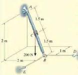
6 Moment of a Force AT A POINT 3D Example: A man exerts a 485 N pull on the rope which is looped around the branch at point A. Determine the moment about point C of this force that exerts on the branch of the tree and state the magnitude of this moment.
7 Moment of a Force AT A POINT 3D Example: r CA TAB
8 Example: Moment of a Force AT A POINT 3D Three forces act on the rod. Determine the resultant moment they create about the flange at O and determine the coordinate direction angles of the moment axis.
9 Solution Moment of a Force AT A POINT 3D Position vectors are directed from point O to each force r OA = {5j} m and r OB = {4i + 5j - 2k} m For resultant moment about O, M (r X F) r X F + r X F + r X F Ro A 1 B 2 C 3 OA OA OB i j k i j k i j k i 40 j 60k N.m
10 Solution For magnitude Moment of a Force AT A POINT 3D M Ro (30) ( 40) (60) N.m For unit vector defining the direction of moment axis, uλ MRo 30i 40 j 60k M Ro i j k
11 Solution Moment of a Force AT A POINT 3D For the coordinate angles of the moment axis, cos ; cos ; cos ;

12 Moment of a Force AT A POINT 3D Example (T): a) Determine the moment of the force F about the point P: b) Find the perpendicular distance D acting on the line of action of the given force that causes the same moment. N m m m m The vector from P to the point of application of F is: r = (12 3) i + (6 4) j + ( 5 1) k = 9 i + 2 j 6 k (m)
13 Moment of a Force AT A POINT 3D Example (T): The moment is: i j k M = r F = = 38i 87j+ 28k P (N - m) The magnitude of M P : M P N - m
14 Moment of a Force AT A POINT 3D Example (T): The perpendicular distance D acting on the line of action of the given force that causes the same moment is D = F M P = N - m 9 N = m The direction of M P tells us both the orientation of the plane of the plane containing D and F and the direction of the moment.
15 Moment of a Force AT A POINT 3D Example (T): The cable tension has a magnitude of kn. Calculate the moment of this cable T, which produces about the base O of the construction crane. TAB
16 Moment of a Force AT A POINT 3D EXAMPLE (T): A force is applied to the tool, to open a gas valve. Find the magnitude of the moment of this force about the point A. A B
 i j k 0 0 M 1 z = 0.125 0.2165 0-60 20 15 = 1{0.125(20) 0.")
17 Moment of a Force AT A POINT 3D A B r AB = {0.25 sin 30 i cos30 j} m = {0.125 i j} m F = {-60 i + 20 j + 15 k} N M z = (r AB F) i j k 0 0 M 1 z = = 1{0.125(20) (-60)} N m = N m

18 Moment of a Force About A LINE 3D Example (T): 3 cables are attached to a bracket. Replace the forces exerted by the cables with: an equivalent resultant force and couple moment acting at point A.

19 Further Reduction of Forces and Couples System

20 Further Reduction of Forces and Couples System

21 Further Reduction of Forces and Couples System

22 Further Reduction of Forces and Couples System

23 Further Reduction of Forces and Couples System

24 Further Reduction of Forces and Couples System

25 Further Reduction of Forces and Couples System Solution: General system of forces and moments x z

26 Equilibrium Conditions Coplanar (2D) General case F 3 F 2 M 2 d 3 o d 1 d 2 F 1 M 1 When an object acted upon by a system of forces & moments is in equilibrium, the following conditions are satisfied: 1. The sum of the forces is zero: F = 0 2. The sum of the moments about any point is zero: M anypo int =0

27 Equilibrium Conditions Coplanar (2D)General case F 3 F 2 M 2 d 3 o d 1 d 2 F 1 M 1 F x = 0, Fy = 0, M o = 0 Necessary Sufficient Body in Equilibrium Fundamental Equations/Conditions for Statics!
28 + 1 unknown 2 unknowns 2 unknowns 3 unknowns + F 0, 0, x = Fy = + M o = 0
29 EQUILIBRIUM EQUATIONS CONDITIONS OF EQUILIBRIUM STUDY THE EQUILIBRIUM OF 3-FORCE SYSTEMS 3 unknowns 5 unknowns 3 unknowns 6 unknowns
 Set 2: Equilibrium of Moments (3 components) + i F x = 0, + j F y = 0, F Z = 0 M x = 0, M y = 0, + i + j + k M z =")
30 Equilibrium Conditions 3D General case There are 2 sets of Independent Equilibrium Equations Set 1: Equilibrium of Forces (3 components) Set 2: Equilibrium of Moments (3 components) + i F x = 0, + j F y = 0, F Z = 0 M x = 0, M y = 0, + i + j + k M z = 0
31 The Free-Body Diagram FBD It is the sketch of the body that shows all the applied known and unknown forces and moments acting on this body. This sketch, shows the particle free (isolated) from its surroundings with all the external forces acting on it. Note that; while showing the externally applied forces and moments, their directions should be indicated. If the directions are not given, ASSUME: Force: + ve for all directions (x, y and z) (i.e. Same direction with the defined axis directions) Moments: + ve for i, j, k components.

32 The Free-Body Diagram FBD To apply equilibrium equations we must account for all known and unknown forces and moments acting on the object by drawing a free-body diagram FBD of the body. Force Types Active Forces : tend to set the body in motion. Reactive Forces : result from constraints or supports and tend to prevent motion
33 Procedure for Analysis Equilibrium Problems 1) Draw Free-Body Diagram FBD Establish the x, y (for 2D) axes and x, y and z (for 3D) axes in any suitable orientation. Label all known and unknown force and moment magnitudes and directions on the FBD. The sense of an unknown force and moment may be assume. 2) Apply equations of equilibrium. Components of the force and moments are positive if directed along a positive axis and negative if directed along a negative axis. 3) If solution yields a negative result the force or the moment is in the opposite sense of that was assumed and showed on the FBD.

34 Supports Forces & couples exerted on an object by its supports are called reactions. E.g. a bridge is held up by the reactions exerted by its supports. support support
35 Support Reactions Reactive Forces General Rule: If a support prevents the translation of a body in a given direction, then a force (REACTION) is developed on the body in that direction. Likewise, if the rotation is prevented, a couple moment (REACTION) is exerted on the body.
36 2 D SUPPORTS


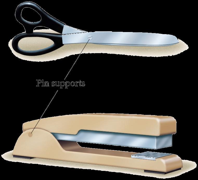
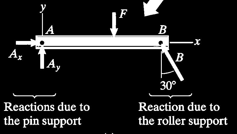
37 Pin Support: Figure a: pin support a bracket to which an object is attached by a smooth pin that passes through the bracket & the object Figure b: side view SYMBOL USED IN NOTEBOOK The arrows indicate the directions of the reactions A x and A y in 2D.

38 Pin Support Details:
39
 to this surface.")
40 Roller Support: It can move freely in the direction parallel to the surface on which it rolls, it can t exert a force parallel to the surface but can exert a force normal (perpendicular) to this surface. The arrow indicate the directions of the reaction A SYMBOL USED IN NOTEBOOK
41 Fixed Support The fixed support shows the supported object literally built into a wall (built-in). SYMBOL USED IN NOTEBOOK A fixed support can exert 2 components of force A X A Y and a couple M A

42 Different Support Types in 2D Different
43 Different Support Types in 2D
44 Different Support Types in 2D


45 Different Support Types in 2 D Unknown is directed along the axis of the short link

46 Different Support Types in 2D

47 Different Support Types in 2D
48 Different Support Types Different Support Types in 2D
 Slider in a slot (c) Slider on a")
49 Different Support Types in 2D (a) Pin in a slot (b) Slider in a slot (c) Slider on a shaft

50 Different 2D Support Types in Practice
51 Example: Free Body Diagram FBD 2D For the given supports and loadings of the body draw its FBD?
52 Example: Free Body Diagram FBD 2D
53 Example: Free Body Diagram FBD 2D
54 Example: Free Body Diagram FBD 2D

55 Free Body Diagram FBD 2D 30
 is under TENSION.")
56 Free Body Diagram FBD 2D PULLEYS When a cable (cord) wraps over a frictionless pulley, definitely each and every portion of this cables (cords) is under TENSION. To satisfy the static equilibrium, the magnitudes of the tension T 1 = T 2 should be the SAME.


57 Free Body Diagram FBD 2D PULLEYS r =15 cm 7.8 kn 7.8 kn 7.8 kn

58 Example: Free Body Diagram FBD 2D The object in this figure has a fixed support at the left end (point A). A cable passing over a pulley is attached to the object at 2 points. Isolate it from its supports & complete the free-body by showing the reactions at the fixed support & the forces exerted by the cable.

59 Free Body Diagram FBD 2D Don t forget the couple at the fixed support, Since the tension in the cable is assumed, on both sides of the pulley, the 2 same forces exerted by the cable having the magnitude T. Once the free-body diagram of an object is obtained, by identifying the loads & reactions acting on it, for equilibrium, the equilibrium equations can be applied.
60 Free Body Diagram FBD 2D Ay Ax
61 Example: Free Body Diagram FBD 2D


62 Example: Free Body Diagram FBD 2D y x y

63 Example: Free Body Diagram FBD 2D
64 Solving rigid-body equilibrium problems 2D CASES
65
66 F direction of forces = 0 M any point = Only TWO unknowns can be found

67 Example: Find the tensions in cables BG and DH if P = kn and Q = 12.5 kn? G H y x
68
69 + + F 0, 0, x = Fy = + M o = 0 Only THREE unknowns can be found
70 Example: Find the reactions at the supports A and D ϴ = 57 o Note that the support at A is PIN type and the support at D is ROLLER type
71 Example: Find the reactions at the supports, if P = 2500 N
72 Example: 25 knm
73 Example: 25 knm 30 o
74 Example: 25 knm 0.8 cos 60 m 0.8 sin 60 m 6 sin 30 kn Ay 1.2 sin 60 m 6 cos 30 kn cos 60 m By Bx
75 EXAMPLE: For the given compound beam find the reactions at supports A and B (ignore the size of the supports).
76 EXAMPLE: For the given compound beam find the reactions at supports A and B (ignore the size of the supports). Note: Seperate the given system into 2 parts as system CD and system AB. Find the reactions at Supports C and D. For system AB apply EQUAL MAGNITUDE BUT OPPOSITE DIRECTION of the reaction values obtained for Support C (due to action-reaction).

77 Example: For the given system, determine the reactions at A, B, C and D (ignore the size of the supports)?
78 A SIMPLE PULLEY 100 N 100 N 100 N 100 N 100 N
79 MULTIPLE PULLIES C B A

80 MULTIPLE PULLIES P /2 P 2T=P P /4 T = P 4T=P
81 Example: Calculate the tension T in the cable which supports 50 kn with the given pulley arregement shown. Note that each pulley is free to rotate about its bearing and has negligible weight compared with the carried load. Ignore the weight of ther cable as well. C B A
82 Solution: C = 12.5 kn 25 kn 12.5 kn 12.5 kn B 25 kn A
83 Example: Relationship between pulled length s of the rope and the elevated height h due to different pulley combinations.
84 Example: Neglecting friction and the radius of the pulley, determine: a) The tension in cable ADB b) Reaction at C. D 150 mm A B C 120 N 80 mm 80 mm 200 mm
85 Example: y x T T R mm A B C 120 N R 1 80 mm 80 mm 200 mm FBD of the beam ABC

86 Example (T): The mass of 700 kg is suspended from a trolley which moves along the crane rail d = 3.5 m. Determine the force along short link BC and the magnitude of the reaction force at pin A.

87 Different Support Types in 3D 1 unknown 1 unknown 1 unknown 3 unknowns 4 unknowns

88 6 unknowns Different Support Types in 3D 5 unknowns 5 unknowns 5 unknowns 5 unknowns

89 Different Support Types in 3D
90 All 2D SUPPORTS Some 3D SUPPORTS

91 Free Body Diagram FBD 3D Example: Ball-and-socket joint at A. Smooth journal bearing at B. Roller support at C.
92 Example: Free Body Diagram FBD 3D

93 Example: Free Body Diagram FBD Ball-and-socket joint at A. BD and BE are cables.

94 Free Body Diagram FBD
95 Solving 3D rigid-body equilibrium problems


96 Example: Determine the reactions due to force F = 300 N, at the fixed support O.
97 Example:
98 Solution: FBD
99 Example: Rod AB subjected to 200N force. Determine the reactions at the ball-and-socket joint A and the tension in cables BD and BE. Note that point C is acting at the middle of the rod AB. z y x
.")

100 Solution: At point A, ball and socket reaction means only reaction forces may occur along 3 axes (no moment). Cable BD under tension along y-axis only and cable BE under tension along x-axis only. Note that point C is at the middle of the two points A and B. FBD
101 Example T: Determine the support reaction at C (ball and socket type) if the applied force at B is F = 3.6 kn.
Engineering Mechanics: Statics in SI Units, 12e
 Engineering Mechanics: Statics in SI Units, 12e 5 Equilibrium of a Rigid Body Chapter Objectives Develop the equations of equilibrium for a rigid body Concept of the free-body diagram for a rigid body
Chapter Objectives. Copyright 2011 Pearson Education South Asia Pte Ltd
 Chapter Objectives To develop the equations of equilibrium for a rigid body. To introduce the concept of the free-body diagram for a rigid body. To show how to solve rigid-body equilibrium problems using
Equilibrium of a Particle
 ME 108 - Statics Equilibrium of a Particle Chapter 3 Applications For a spool of given weight, what are the forces in cables AB and AC? Applications For a given weight of the lights, what are the forces
The case where there is no net effect of the forces acting on a rigid body
 The case where there is no net effect of the forces acting on a rigid body Outline: Introduction and Definition of Equilibrium Equilibrium in Two-Dimensions Special cases Equilibrium in Three-Dimensions
Ishik University / Sulaimani Architecture Department. Structure. ARCH 214 Chapter -5- Equilibrium of a Rigid Body
 Ishik University / Sulaimani Architecture Department 1 Structure ARCH 214 Chapter -5- Equilibrium of a Rigid Body CHAPTER OBJECTIVES To develop the equations of equilibrium for a rigid body. To introduce
EQUILIBRIUM OF A RIGID BODY & FREE-BODY DIAGRAMS
 Today s Objectives: Students will be able to: EQUILIBRIUM OF A RIGID BODY & FREE-BODY DIAGRAMS a) Identify support reactions, and, b) Draw a free-body diagram. In-Class Activities: Check Homework Reading
STATICS. Bodies. Vector Mechanics for Engineers: Statics VECTOR MECHANICS FOR ENGINEERS: Design of a support
 4 Equilibrium CHAPTER VECTOR MECHANICS FOR ENGINEERS: STATICS Ferdinand P. Beer E. Russell Johnston, Jr. Lecture Notes: J. Walt Oler Texas Tech University of Rigid Bodies 2010 The McGraw-Hill Companies,
TUTORIAL SHEET 1. magnitude of P and the values of ø and θ. Ans: ø =74 0 and θ= 53 0
 TUTORIAL SHEET 1 1. The rectangular platform is hinged at A and B and supported by a cable which passes over a frictionless hook at E. Knowing that the tension in the cable is 1349N, determine the moment
3.1 CONDITIONS FOR RIGID-BODY EQUILIBRIUM
 3.1 CONDITIONS FOR RIGID-BODY EQUILIBRIUM Consider rigid body fixed in the x, y and z reference and is either at rest or moves with reference at constant velocity Two types of forces that act on it, the
ENGR-1100 Introduction to Engineering Analysis. Lecture 13
 ENGR-1100 Introduction to Engineering Analysis Lecture 13 EQUILIBRIUM OF A RIGID BODY & FREE-BODY DIAGRAMS Today s Objectives: Students will be able to: a) Identify support reactions, and, b) Draw a free-body
Statics Chapter II Fall 2018 Exercises Corresponding to Sections 2.1, 2.2, and 2.3
 Statics Chapter II Fall 2018 Exercises Corresponding to Sections 2.1, 2.2, and 2.3 2 3 Determine the magnitude of the resultant force FR = F1 + F2 and its direction, measured counterclockwise from the
Announcements. Equilibrium of a Rigid Body
 Announcements Equilibrium of a Rigid Body Today s Objectives Identify support reactions Draw a free body diagram Class Activities Applications Support reactions Free body diagrams Examples Engr221 Chapter
5.2 Rigid Bodies and Two-Dimensional Force Systems
 5.2 Rigid odies and Two-Dimensional Force Systems 5.2 Rigid odies and Two-Dimensional Force Systems Procedures and Strategies, page 1 of 1 Procedures and Strategies for Solving Problems Involving Equilibrium
Eng Sample Test 4
 1. An adjustable tow bar connecting the tractor unit H with the landing gear J of a large aircraft is shown in the figure. Adjusting the height of the hook F at the end of the tow bar is accomplished by
Chapter - 1. Equilibrium of a Rigid Body
 Chapter - 1 Equilibrium of a Rigid Body Dr. Rajesh Sathiyamoorthy Department of Civil Engineering, IIT Kanpur hsrajesh@iitk.ac.in; http://home.iitk.ac.in/~hsrajesh/ Condition for Rigid-Body Equilibrium
The centroid of an area is defined as the point at which (12-2) The distance from the centroid of a given area to a specified axis may be found by
 The distance from the centroid of a given area to a specified axis may be found by") Unit 12 Centroids Page 12-1 The centroid of an area is defined as the point at which (12-2) The distance from the centroid of a given area to a specified axis may be found by (12-5) For the area shown
Unit 12 Centroids Page 12-1 The centroid of an area is defined as the point at which (12-2) The distance from the centroid of a given area to a specified axis may be found by (12-5) For the area shown
Engineering Mechanics: Statics in SI Units, 12e
 Engineering Mechanics: Statics in SI Units, 12e 3 Equilibrium of a Particle Chapter Objectives To introduce the concept of the free-body diagram for a particle To show how to solve particle equilibrium
Equilibrium. Rigid Bodies VECTOR MECHANICS FOR ENGINEERS: STATICS. Eighth Edition CHAPTER. Ferdinand P. Beer E. Russell Johnston, Jr.
 Eighth E 4 Equilibrium CHAPTER VECTOR MECHANICS FOR ENGINEERS: STATICS Ferdinand P. Beer E. Russell Johnston, Jr. Lecture Notes: J. Walt Oler Texas Tech University of Rigid Bodies Contents Introduction
KINGS COLLEGE OF ENGINEERING ENGINEERING MECHANICS QUESTION BANK UNIT I - PART-A
 KINGS COLLEGE OF ENGINEERING ENGINEERING MECHANICS QUESTION BANK Sub. Code: CE1151 Sub. Name: Engg. Mechanics UNIT I - PART-A Sem / Year II / I 1.Distinguish the following system of forces with a suitable
VALLIAMMAI ENGINEERING COLLEGE SRM NAGAR, KATTANKULATHUR DEPARTMENT OF MECHANICAL ENGINEERING
 VALLIAMMAI ENGINEERING COLLEGE SRM NAGAR, KATTANKULATHUR 603203 DEPARTMENT OF MECHANICAL ENGINEERING BRANCH: MECHANICAL YEAR / SEMESTER: I / II UNIT 1 PART- A 1. State Newton's three laws of motion? 2.
When a rigid body is in equilibrium, both the resultant force and the resultant couple must be zero.
 When a rigid body is in equilibrium, both the resultant force and the resultant couple must be zero. 0 0 0 0 k M j M i M M k R j R i R F R z y x z y x Forces and moments acting on a rigid body could be
Engineering Mechanics: Statics in SI Units, 12e
 Engineering Mechanics: Statics in SI Units, 12e 3 Equilibrium of a Particle 1 Chapter Objectives Concept of the free-body diagram for a particle Solve particle equilibrium problems using the equations
EQUILIBRIUM OF A RIGID BODY
 EQUILIBRIUM OF A RIGID BODY Today s Objectives: Students will be able to a) Identify support reactions, and, b) Draw a free diagram. APPLICATIONS A 200 kg platform is suspended off an oil rig. How do we
Engineering Mechanics Statics
 Mechanical Systems Engineering _ 2016 Engineering Mechanics Statics 7. Equilibrium of a Rigid Body Dr. Rami Zakaria Conditions for Rigid-Body Equilibrium Forces on a particle Forces on a rigid body The
Sample 5. Determine the tension in the cable and the horizontal and vertical components of reaction at the pin A. Neglect the size of the pulley.
 Sample 1 The tongs are designed to handle hot steel tubes which are being heat-treated in an oil bath. For a 20 jaw opening, what is the minimum coefficient of static friction between the jaws and the
Chapter 5: Equilibrium of a Rigid Body
 Chapter 5: Equilibrium of a Rigid Body Chapter Objectives To develop the equations of equilibrium for a rigid body. To introduce the concept of a free-body diagram for a rigid body. To show how to solve
Statics deal with the condition of equilibrium of bodies acted upon by forces.
 Mechanics It is defined as that branch of science, which describes and predicts the conditions of rest or motion of bodies under the action of forces. Engineering mechanics applies the principle of mechanics
1. Replace the given system of forces acting on a body as shown in figure 1 by a single force and couple acting at the point A.
 Code No: Z0321 / R07 Set No. 1 I B.Tech - Regular Examinations, June 2009 CLASSICAL MECHANICS ( Common to Mechanical Engineering, Chemical Engineering, Mechatronics, Production Engineering and Automobile
The Laws of Motion. Newton s first law Force Mass Newton s second law Gravitational Force Newton s third law Examples
 The Laws of Motion Newton s first law Force Mass Newton s second law Gravitational Force Newton s third law Examples Gravitational Force Gravitational force is a vector Expressed by Newton s Law of Universal
6.6 FRAMES AND MACHINES APPLICATIONS. Frames are commonly used to support various external loads.
 6.6 FRAMES AND MACHINES APPLICATIONS Frames are commonly used to support various external loads. How is a frame different than a truss? How can you determine the forces at the joints and supports of a
11.1 Virtual Work Procedures and Strategies, page 1 of 2
 11.1 Virtual Work 11.1 Virtual Work rocedures and Strategies, page 1 of 2 rocedures and Strategies for Solving roblems Involving Virtual Work 1. Identify a single coordinate, q, that will completely define
Student AP Physics 1 Date. Newton s Laws B FR
 Student AP Physics 1 Date Newton s Laws B FR #1 A block is at rest on a rough inclined plane and is connected to an object with the same mass as shown. The rope may be considered massless; and the pulley
SOLUTION 8 1. a+ M B = 0; N A = 0. N A = kn = 16.5 kn. Ans. + c F y = 0; N B = 0
 8 1. The mine car and its contents have a total mass of 6 Mg and a center of gravity at G. If the coefficient of static friction between the wheels and the tracks is m s = 0.4 when the wheels are locked,
5. Plane Kinetics of Rigid Bodies
 5. Plane Kinetics of Rigid Bodies 5.1 Mass moments of inertia 5.2 General equations of motion 5.3 Translation 5.4 Fixed axis rotation 5.5 General plane motion 5.6 Work and energy relations 5.7 Impulse
ENGINEERING MECHANICS SOLUTIONS UNIT-I
 LONG QUESTIONS ENGINEERING MECHANICS SOLUTIONS UNIT-I 1. A roller shown in Figure 1 is mass 150 Kg. What force P is necessary to start the roller over the block A? =90+25 =115 = 90+25.377 = 115.377 = 360-(115+115.377)
1. Please complete the following short problems.
 Name 1. Please complete the following short problems. For parts 1A and 1B, we will consider three M88 recovery vehicles pulling an M1 tank back onto the road as shown below. F2 F1 50 M88 #1 50 M88 #2 y
EQUATIONS OF EQUILIBRIUM & TWO- AND THREE-FORCE MEMEBERS
 EQUATIONS OF EQUILIBRIUM & TWO- AND THREE-FORCE MEMEBERS Today s Objectives: Students will be able to: a) Apply equations of equilibrium to solve for unknowns, and b) Recognize two-force members. In-Class
EQUILIBRIUM OF RIGID BODIES
 EQUILIBRIUM OF RIGID BODIES Equilibrium A body in equilibrium is at rest or can translate with constant velocity F = 0 M = 0 EQUILIBRIUM IN TWO DIMENSIONS Case where the force system acting on a rigid
Equilibrium & Elasticity
 PHYS 101 Previous Exam Problems CHAPTER 12 Equilibrium & Elasticity Static equilibrium Elasticity 1. A uniform steel bar of length 3.0 m and weight 20 N rests on two supports (A and B) at its ends. A block
When a rigid body is in equilibrium, both the resultant force and the resultant couple must be zero.
 When a rigid body is in equilibrium, both the resultant force and the resultant couple must be zero. 0 0 0 0 k M j M i M M k R j R i R F R z y x z y x Forces and moments acting on a rigid body could be
EQUATIONS OF EQUILIBRIUM & TWO- AND THREE-FORCE MEMBERS
 EQUATIONS OF EQUILIBRIUM & TWO- AND THREE-FORCE MEMBERS Today s Objectives: Students will be able to: a) Apply equations of equilibrium to solve for unknowns, and, b) Recognize two-force members. APPLICATIONS
Name. ME 270 Fall 2005 Final Exam PROBLEM NO. 1. Given: A distributed load is applied to the top link which is, in turn, supported by link AC.
 Name ME 270 Fall 2005 Final Exam PROBLEM NO. 1 Given: A distributed load is applied to the top link which is, in turn, supported by link AC. Find: a) Draw a free body diagram of link BCDE and one of link
Q16.: A 5.0 kg block is lowered with a downward acceleration of 2.8 m/s 2 by means of a rope. The force of the block on the rope is:(35 N, down)
") Old Exam Question Ch. 5 T072 Q13.Two blocks of mass m 1 = 24.0 kg and m 2, respectively, are connected by a light string that passes over a massless pulley as shown in Fig. 2. If the tension in the string
Old Exam Question Ch. 5 T072 Q13.Two blocks of mass m 1 = 24.0 kg and m 2, respectively, are connected by a light string that passes over a massless pulley as shown in Fig. 2. If the tension in the string
Announcements. Trusses Method of Joints
 Announcements Mountain Dew is an herbal supplement Today s Objectives Define a simple truss Trusses Method of Joints Determine the forces in members of a simple truss Identify zero-force members Class
To show how to determine the forces in the members of a truss using the method of joints and the method of sections.
 5 Chapter Objectives To show how to determine the forces in the members of a truss using the method of joints and the method of sections. To analyze the forces acting on the members of frames and machines
Plane Motion of Rigid Bodies: Forces and Accelerations
 Plane Motion of Rigid Bodies: Forces and Accelerations Reference: Beer, Ferdinand P. et al, Vector Mechanics for Engineers : Dynamics, 8 th Edition, Mc GrawHill Hibbeler R.C., Engineering Mechanics: Dynamics,
DYNAMICS ME HOMEWORK PROBLEM SETS
 DYNAMICS ME 34010 HOMEWORK PROBLEM SETS Mahmoud M. Safadi 1, M.B. Rubin 2 1 safadi@technion.ac.il, 2 mbrubin@technion.ac.il Faculty of Mechanical Engineering Technion Israel Institute of Technology Spring
Chapter 6: Structural Analysis
 Chapter 6: Structural Analysis Chapter Objectives To show how to determine the forces in the members of a truss using the method of joints and the method of sections. To analyze the forces acting on the
Calculate the force F needed to produce a horizontal component of 300 N on the sledge (1)
") 1. A heavy sledge is pulled across snowfields. The diagram shows the direction of the force F exerted on the sledge. Once the sledge is moving, the average horizontal force needed to keep it moving at
1. A heavy sledge is pulled across snowfields. The diagram shows the direction of the force F exerted on the sledge. Once the sledge is moving, the average horizontal force needed to keep it moving at
Lecture 0. Statics. Module 1. Overview of Mechanics Analysis. IDeALab. Prof. Y.Y.KIM. Solid Mechanics
 Lecture 0. Statics Module 1. Overview of Mechanics Analysis Overview of Mechanics Analysis Procedure of Solving Mechanics Problems Objective : Estimate the force required in the flexor muscle Crandall,
Mechanics of Materials
 Mechanics of Materials 2. Introduction Dr. Rami Zakaria References: 1. Engineering Mechanics: Statics, R.C. Hibbeler, 12 th ed, Pearson 2. Mechanics of Materials: R.C. Hibbeler, 9 th ed, Pearson 3. Mechanics
Chapter 6: Structural Analysis
 Chapter 6: Structural Analysis APPLICATIONS Trusses are commonly used to support a roof. For a given truss geometry and load, how can we determine the forces in the truss members and select their sizes?
SIMPLE TRUSSES, THE METHOD OF JOINTS, & ZERO-FORCE MEMBERS
 SIMPLE TRUSSES, THE METHOD OF JOINTS, & ZERO-FORCE MEMBERS Today s Objectives: Students will be able to: a) Define a simple truss. b) Determine the forces in members of a simple truss. c) Identify zero-force
Physics 101 Lecture 5 Newton`s Laws
 Physics 101 Lecture 5 Newton`s Laws Dr. Ali ÖVGÜN EMU Physics Department The Laws of Motion q Newton s first law q Force q Mass q Newton s second law q Newton s third law qfrictional forces q Examples
The University of Melbourne Engineering Mechanics
 The University of Melbourne 436-291 Engineering Mechanics Tutorial Eleven Instantaneous Centre and General Motion Part A (Introductory) 1. (Problem 5/93 from Meriam and Kraige - Dynamics) For the instant
PHYS 101 Previous Exam Problems. Force & Motion I
 PHYS 101 Previous Exam Problems CHAPTER 5 Force & Motion I Newton s Laws Vertical motion Horizontal motion Mixed forces Contact forces Inclines General problems 1. A 5.0-kg block is lowered with a downward
where x and y are any two non-parallel directions in the xy-plane. iii) One force equation and one moment equation.
 One force equation and one moment equation.") Concurrent Force System ( of Particles) Recall that the resultant of a concurrent force system is a force F R that passes through the point of concurrency, which we label as point O. The moment equation,
Concurrent Force System ( of Particles) Recall that the resultant of a concurrent force system is a force F R that passes through the point of concurrency, which we label as point O. The moment equation,
Course Overview. Statics (Freshman Fall) Dynamics: x(t)= f(f(t)) displacement as a function of time and applied force
 Dynamics: x(t)= f(f(t)) displacement as a function of time and applied force") Course Overview Statics (Freshman Fall) Engineering Mechanics Dynamics (Freshman Spring) Strength of Materials (Sophomore Fall) Mechanism Kinematics and Dynamics (Sophomore Spring ) Aircraft structures
Course Overview Statics (Freshman Fall) Engineering Mechanics Dynamics (Freshman Spring) Strength of Materials (Sophomore Fall) Mechanism Kinematics and Dynamics (Sophomore Spring ) Aircraft structures
Vector Mechanics: Statics
 PDHOnline Course G492 (4 PDH) Vector Mechanics: Statics Mark A. Strain, P.E. 2014 PDH Online PDH Center 5272 Meadow Estates Drive Fairfax, VA 22030-6658 Phone & Fax: 703-988-0088 www.pdhonline.org www.pdhcenter.com
CIV100: Mechanics. Lecture Notes. Module 1: Force & Moment in 2D. You Know What to Do!
 CIV100: Mechanics Lecture Notes Module 1: Force & Moment in 2D By: Tamer El-Diraby, PhD, PEng. Associate Prof. & Director, I2C University of Toronto Acknowledgment: Hesham Osman, PhD and Jinyue Zhang,
EQUATIONS OF EQUILIBRIUM & TWO-AND THREE-FORCE MEMEBERS
 EQUATIONS OF EQUILIBRIUM & TWO-AND THREE-FORCE MEMEBERS Today s Objectives: Students will be able to: a) Apply equations of equilibrium to solve for unknowns, and, b) Recognize two-force members. READING
1 MR SAMPLE EXAM 3 FALL 2013
 SAMPLE EXAM 3 FALL 013 1. A merry-go-round rotates from rest with an angular acceleration of 1.56 rad/s. How long does it take to rotate through the first rev? A) s B) 4 s C) 6 s D) 8 s E) 10 s. A wheel,
Sara Rwentambo. PHYS 1007 AB
 Topics: Free body diagrams (FBDs) Static friction and kinetic friction Tension and acceleration of a system Tension in dynamic equilibrium (bonus question) Opener: Find Your Free Body Diagram Group Activity!
MEE224: Engineering Mechanics Lecture 4
 Lecture 4: Structural Analysis Part 1: Trusses So far we have only analysed forces and moments on a single rigid body, i.e. bars. Remember that a structure is a formed by and this lecture will investigate
AP Physics C: Rotation II. (Torque and Rotational Dynamics, Rolling Motion) Problems
 Problems") AP Physics C: Rotation II (Torque and Rotational Dynamics, Rolling Motion) Problems 1980M3. A billiard ball has mass M, radius R, and moment of inertia about the center of mass I c = 2 MR²/5 The ball is
AP Physics C: Rotation II (Torque and Rotational Dynamics, Rolling Motion) Problems 1980M3. A billiard ball has mass M, radius R, and moment of inertia about the center of mass I c = 2 MR²/5 The ball is
Physics 8, Fall 2017, Practice Exam.
 Physics 8, Fall 2017, Practice Exam. Name: This open-book take-home exam is 10% of your course grade. (The in-class final exam will be 20% of your course grade. For the in-class exam, you can bring one
You may use g = 10 m/s 2, sin 60 = 0.87, and cos 60 = 0.50.
 1. A child pulls a 15kg sled containing a 5kg dog along a straight path on a horizontal surface. He exerts a force of a 55N on the sled at an angle of 20º above the horizontal. The coefficient of friction
STATICS. Friction VECTOR MECHANICS FOR ENGINEERS: Eighth Edition CHAPTER. Ferdinand P. Beer E. Russell Johnston, Jr.
 Eighth E 8 Friction CHAPTER VECTOR MECHANICS FOR ENGINEERS: STATICS Ferdinand P. Beer E. Russell Johnston, Jr. Lecture Notes: J. Walt Oler Texas Tech University Contents Introduction Laws of Dry Friction.
PAT 101 FUNDAMENTAL OF ENGINEERING MECHANICS EQUILIBREQUILIBRIUM OF A RIGID BODY IUM OF A RIGID BODY
 PAT 101 FUNDAMENTAL OF ENGINEERING MECHANICS EQUILIBREQUILIBRIUM OF A RIGID BODY IUM OF A RIGID BODY MARDHIAH FARHANA BINT OMAR Week 5-6 EQUILIBRIUM OF A RIGID BODY Conditions for Rigid Equilibrium Free-Body
Name Date Period PROBLEM SET: ROTATIONAL DYNAMICS
 Accelerated Physics Rotational Dynamics Problem Set Page 1 of 5 Name Date Period PROBLEM SET: ROTATIONAL DYNAMICS Directions: Show all work on a separate piece of paper. Box your final answer. Don t forget
Unit 5 Forces I- Newton s First & Second Law
 Unit 5 Forces I- Newton s First & Second Law Unit is the NEWTON(N) Is by definition a push or a pull Does force need a Physical contact? Can exist during physical contact(tension, Friction, Applied Force)
Announcements. Equilibrium of a Particle in 2-D
 nnouncements Equilibrium of a Particle in 2-D Today s Objectives Draw a free body diagram (FBD) pply equations of equilibrium to solve a 2-D problem Class ctivities pplications What, why, and how of a
Rotation review packet. Name:
 Rotation review packet. Name:. A pulley of mass m 1 =M and radius R is mounted on frictionless bearings about a fixed axis through O. A block of equal mass m =M, suspended by a cord wrapped around the
Dept of ECE, SCMS Cochin
 B B2B109 Pages: 3 Reg. No. Name: APJ ABDUL KALAM TECHNOLOGICAL UNIVERSITY SECOND SEMESTER B.TECH DEGREE EXAMINATION, MAY 2017 Course Code: BE 100 Course Name: ENGINEERING MECHANICS Max. Marks: 100 Duration:
(a) On the dots below that represent the students, draw and label free-body diagrams showing the forces on Student A and on Student B.
 On the dots below that represent the students, draw and label free-body diagrams showing the forces on Student A and on Student B.") 2003 B1. (15 points) A rope of negligible mass passes over a pulley of negligible mass attached to the ceiling, as shown above. One end of the rope is held by Student A of mass 70 kg, who is at rest on
2003 B1. (15 points) A rope of negligible mass passes over a pulley of negligible mass attached to the ceiling, as shown above. One end of the rope is held by Student A of mass 70 kg, who is at rest on
EQUATIONS OF EQUILIBRIUM & TWO- AND THREE-FORCE MEMEBERS
 EQUATIONS OF EQUILIBRIUM & TWO- AND THREE-FORCE MEMEBERS Today s Objectives: Students will be able to: a) Apply equations of equilibrium to solve for unknowns, and, b) Recognize two-force members. In-Class
ENGR-1100 Introduction to Engineering Analysis. Lecture 19
 ENGR-1100 Introduction to Engineering Analysis Lecture 19 SIMPLE TRUSSES, THE METHOD OF JOINTS, & ZERO-FORCE MEMBERS Today s Objectives: Students will be able to: In-Class Activities: a) Define a simple
h p://edugen.wileyplus.com/edugen/courses/crs1404/pc/c06/c2hlch... 1 of 4 16-Sep-12 19:20 CHAPTER 6
 Bob Wickley/SUPERSTOCKThe fr... 1 of 4 16-Sep-12 19:20 CHAPTER 6 Bob Wickley/SUPERSTOCKThe fr... 2 of 4 16-Sep-12 19:20 Bob Wickley/SUPERSTOCK Bob Wickley/SUPERSTOCKThe fr... 3 of 4 16-Sep-12 19:20 The
 Connected Bodies 1. Two 10 kg bodies are attached to a spring balance as shown in figure. The reading of the balance will be 10 kg 10 kg 1) 0 kg-wt ) 10 kg-wt 3) Zero 4) 5 kg-wt. In the given arrangement,
EQUILIBRIUM OF A PARTICLE, THE FREE-BODY DIAGRAM & COPLANAR FORCE SYSTEMS
 EQUILIBRIUM OF PRTICLE, THE FREE-BODY DIGRM & COPLNR FORCE SYSTEMS Today s Objectives: Students will be able to : a) Draw a free body diagram (FBD), and, b) pply equations of equilibrium to solve a 2-D
HATZIC SECONDARY SCHOOL
 HATZIC SECONDARY SCHOOL PROVINCIAL EXAMINATION ASSIGNMENT VECTOR DYNAMICS MULTIPLE CHOICE / 45 OPEN ENDED / 75 TOTAL / 120 NAME: 1. Unless acted on by an external net force, an object will stay at rest
STRESS. Bar. ! Stress. ! Average Normal Stress in an Axially Loaded. ! Average Shear Stress. ! Allowable Stress. ! Design of Simple Connections
 STRESS! Stress Evisdom! verage Normal Stress in an xially Loaded ar! verage Shear Stress! llowable Stress! Design of Simple onnections 1 Equilibrium of a Deformable ody ody Force w F R x w(s). D s y Support
JNTU World. Subject Code: R13110/R13
 Set No - 1 I B. Tech I Semester Regular Examinations Feb./Mar. - 2014 ENGINEERING MECHANICS (Common to CE, ME, CSE, PCE, IT, Chem E, Aero E, AME, Min E, PE, Metal E) Time: 3 hours Max. Marks: 70 Question
TEST REPORT. Question file: P Copyright:
 Date: February-12-16 Time: 2:00:28 PM TEST REPORT Question file: P12-2006 Copyright: Test Date: 21/10/2010 Test Name: EquilibriumPractice Test Form: 0 Test Version: 0 Test Points: 138.00 Test File: EquilibriumPractice
Chapter 4. Forces and Newton s Laws of Motion. continued
 Chapter 4 Forces and Newton s Laws of Motion continued 4.9 Static and Kinetic Frictional Forces When an object is in contact with a surface forces can act on the objects. The component of this force acting
Unit 5 Forces I- Newtonʼ s First & Second Law
 Unit 5 orces I- Newtonʼ s irst & Second Law Unit is the NEWTON(N) Is by definition a push or a pull Does force need a Physical contact? Can exist during physical contact(tension, riction, Applied orce)
Physics 2211 ABC Quiz #3 Solutions Spring 2017
 Physics 2211 ABC Quiz #3 Solutions Spring 2017 I. (16 points) A block of mass m b is suspended vertically on a ideal cord that then passes through a frictionless hole and is attached to a sphere of mass
Static Equilibrium. University of Arizona J. H. Burge
 Static Equilibrium Static Equilibrium Definition: When forces acting on an object which is at rest are balanced, then the object is in a state of static equilibrium. - No translations - No rotations In
Chapter 8. Rotational Equilibrium and Rotational Dynamics. 1. Torque. 2. Torque and Equilibrium. 3. Center of Mass and Center of Gravity
 Chapter 8 Rotational Equilibrium and Rotational Dynamics 1. Torque 2. Torque and Equilibrium 3. Center of Mass and Center of Gravity 4. Torque and angular acceleration 5. Rotational Kinetic energy 6. Angular
FE Sta'cs Review. Torch Ellio0 (801) MCE room 2016 (through 2000B door)
 MCE room 2016 (through 2000B door)") FE Sta'cs Review h0p://www.coe.utah.edu/current- undergrad/fee.php Scroll down to: Sta'cs Review - Slides Torch Ellio0 ellio0@eng.utah.edu (801) 587-9016 MCE room 2016 (through 2000B door) Posi'on and
FE Sta'cs Review h0p://www.coe.utah.edu/current- undergrad/fee.php Scroll down to: Sta'cs Review - Slides Torch Ellio0 ellio0@eng.utah.edu (801) 587-9016 MCE room 2016 (through 2000B door) Posi'on and
ENGI 1313 Mechanics I
 ENGI 1313 Mechanics I Lecture 25: Equilibrium of a Rigid Body Shawn Kenny, Ph.D., P.Eng. Assistant Professor Faculty of Engineering and Applied Science Memorial University of Newfoundland spkenny@engr.mun.ca
Force and Moment. Figure 1 Figure 2
 Force and Moment 1 Determine the magnitude and direction of the resultant of the two forces shown, using (a) the parallelogram law (b) the sine law. [1391 N, 47.8 ] Figure 1 Figure 2 2 The force F of magnitude
D : SOLID MECHANICS. Q. 1 Q. 9 carry one mark each. Q.1 Find the force (in kn) in the member BH of the truss shown.
 in the member BH of the truss shown.") D : SOLID MECHANICS Q. 1 Q. 9 carry one mark each. Q.1 Find the force (in kn) in the member BH of the truss shown. Q.2 Consider the forces of magnitude F acting on the sides of the regular hexagon having
D : SOLID MECHANICS Q. 1 Q. 9 carry one mark each. Q.1 Find the force (in kn) in the member BH of the truss shown. Q.2 Consider the forces of magnitude F acting on the sides of the regular hexagon having
CHAPTER 2: EQUILIBRIUM OF RIGID BODIES
 For a rigid body to be in equilibrium, the net force as well as the net moment about any arbitrary point O must be zero Summation of all external forces. Equilibrium: Sum of moments of all external forces.
7.6 Journal Bearings
 7.6 Journal Bearings 7.6 Journal Bearings Procedures and Strategies, page 1 of 2 Procedures and Strategies for Solving Problems Involving Frictional Forces on Journal Bearings For problems involving a
PHYSICS - CLUTCH CH 13: ROTATIONAL EQUILIBRIUM.
 !! www.clutchprep.com EXAMPLE: POSITION OF SECOND KID ON SEESAW EXAMPLE: A 4 m-long seesaw 50 kg in mass and of uniform mass distribution is pivoted on a fulcrum at its middle, as shown. Two kids sit on
E 490 FE Exam Prep. Engineering Mechanics
 E 490 FE Exam Prep Engineering Mechanics 2008 E 490 Course Topics Statics Newton s Laws of Motion Resultant Force Systems Moment of Forces and Couples Equilibrium Pulley Systems Trusses Centroid of an
Questions from all units
 Questions from all units S.NO 1. 1 UNT NO QUESTON Explain the concept of force and its characteristics. BLOOMS LEVEL LEVEL 2. 2 Explain different types of force systems with examples. Determine the magnitude
A.M. MONDAY, 25 January hours
 GCE S/ level 980/01 MTHEMTICS M1 Mechanics 1.M. MONDY, 25 January 2010 1 1 2 hours W10 0980 01 1 DDITIONL MTERILS In addition to this examination paper, you will need: a 12 page answer book; a Formula
Static Equilibrium; Torque
 Static Equilibrium; Torque The Conditions for Equilibrium An object with forces acting on it, but that is not moving, is said to be in equilibrium. The first condition for equilibrium is that the net force