DEEP FOUNDATIONS. Lesson 09 - Topic 4 Drilled Shafts
|
|
|
- Bennett Young
- 6 years ago
- Views:
Transcription
1 DEEP FOUNDATIONS Lesson 09 - Topic 4 Drilled Shafts
2 Learning Outcomes gat the end of this session, the participant will be able to: - Contrast driven piles and drilled shafts - Compare mobilization of base (tip) and side (shaft) resistance - Describe drilled shaft construction processes - Discuss the need for quality control for drilled shaft construction
3 Definitions Figure 9-56
4 Driven Piles vs Drilled Shafts gdrilled shaft is installed in a drilled hole, unlike the driven pile gwet concrete is placed in the drilled hole and cures directly against the soil forming the walls of the borehole - Side-support (casing and/or slurry) may be necessary for stabilization of the open hole and may be left in place ginstallation method and equipment varies with the subsurface conditions
5 Advantages of Drilled Shafts gconstruction equipment is mobile and construction can proceed rapidly gexcavated geomaterials can be examined gfor end-bearing bearing situations, the soil beneath the tip may be examined or probed for weaker materials gchanges in shaft size may be made during construction
6 Advantages of Drilled Shafts gheave and settlement at the ground is normally small gpersonnel, equipment and materials for construction are readily available gnoise and vibration level from the equipment is less than other forms of construction for deep foundations (e.g., driven piles)
7 Advantages of Drilled Shafts gapplicable to a wide variety of subsurface conditions, e.g., can be constructed through cobbles and for many feet into hard rock as well as frozen ground guse of a large single drilled shaft (without pile cap) is possible gextensive data bases documenting load-transfer information are available
8 Advantages of Drilled Shafts gsmaller footprint than a footing and can thus be constructed near railroad, existing structures and in constricted areas gshafts may be more economical than spread footing, particularly when the foundation support layer is deeper than 10-ft below the ground or at water crossings
9 Special Considerations for Drilled Shafts gconstruction procedures are critical to the quality of the drilled shaft gknowledgeable inspection is required gnot normally used in deep deposits of soft clay or in situations where artesian pressures exist gstatic load tests to verify ultimate capacity of large diameter shafts are very costly
10 Effect of Subsurface Conditions on Drilled Shafts gcaving soils - Temporary casing or other side support gflowing groundwater - Leaching of concrete - Use of slurry gartesian water conditions - Could cause collapse of the shaft excavation gcobbles and boulders - Sometimes require special tools
11 Effect of Subsurface Conditions on Drilled Shafts g Presence of existing foundations and structures - Loss of ground volume into the exacation g Landfill material that cannot be excavated - e.g., an old car body g Rock - Specialized drilling tools g Weak stratum below base of shaft - May need to extend shaft through the weaker layer
12 Estimating Ultimate Axial Capacity of Shafts in Soils gultimate capacity, Q ult, in compression Q ult = Q S + Q T W gultimate capacity, Q ult, in uplift Q ult 0.7Q S + W
13 Geotechnical Allowable Shaft Load, Q all all Q all all = Q ult / FS gfs is the factor of safety gusually FS = 2.5 assuming a normal level of field quality control during shaft construction. Normal is based on the minimum recommendations of FHWA gif a static load test is performed, FS=2.0 may be used
14 Computation of Geotechnical Axial Capacity gcohesive soils - Total stress for undrained conditions Similar to Tomlinson method for driven piles - Effective stress for drained conditions gcohesionless soils - Effective stress method for drained loading conditions
15 Cohesive soils Side Resistance gside resistance (Eq( Eq ) 9 Q S = πd N i= 1 α i S ui Δz gα is the adhesion factor as follows: gultimate unit side load transfer i α = 0.55 for S p 1. 5 ( p 1.5) u a 1.5 Su pa α = Su a for 2. 5 f si = α i S ui
16 Non-contributing zones
17 Side Resistance Figure 9-58 Mobilization in Cohesive Soils
18 Cohesive soils Tip Resistance gtip resistance (Eq( Eq ) 9 Q T = q T A T = N c s ut A t gα is the adhesion factor as follows: N c = 6.0[1+0.2(z/D)]; N c 9
19 Unit Tip Resistance in Cohesive Soils q TR = (2.5/[aD/ b]) q T where D is the diameter of shaft in inches, a = (z/d) with a 0.015, and b = 0.45(s ut ) 0.5 with 0.5 b 1.5
20 Tip Resistance Mobilization Figure 9-59 in Cohesive Soils
21 Cohesionless soils Side Resistance gside resistance (Eq( Eq ) 9 Q S = πd N i= 1 γ / i z i β i Δz gβ is the adhesion factor as follows: where: i i β = z with 1.2 > βi > gultimate unit side load transfer ( 4( ksf) f si = β i σ / vi i
22 Side Resistance Mobilization in Cohesionless Soils Figure 9-60
23 Cohesionless soils Tip Resistance gtip resistance (Eq( Eq ) 9 Q T = q T A T For N 60 75: q T = 1.2N 60 in ksf For N 60 > 75: q T = 90 ksf greduced tip resistance for large size shafts (D is shaft diameter in inches) q TR = [50/(12D)] q T
24 Tip Resistance Mobilization in Cohesionless Soils Figure 9-61
25 Axial Shaft Capacity in Layered Soils gdivide subsurface profile into layers gin each layer use the appropriate method gsum the resistances from each layer
26 Group Action, Group Settlement, Downdrag and Lateral Loads gsimilar to driven piles grefer to FHWA (1999) publication for guidance
27 Example 9-59 gusing FS=2.5, size a shaft for resisting 170 tons of vertical design load N 60 -values N 60 = 11 N 60 = 14 N 60 = 14 N 60 = 22 N 60 = 12 N 60 = 19 N 60 = 21 N 60 = 37
28 Example 9-59 gfs=2.5 gultimate axial load = (2.5)(170) = 425 tons gassume a 3-ft 3 diameter straight shaft gthus, circumference = πd = 9.42-ft gassume a shaft length of 60-ft guse β formulation as follows Q S = πd N i= 1 γ / i z i β i Δz i where: β = z with 1.2 > βi > i i
29 Example 9-59 gcompute side resistance with depth Depth Interval, Δz, ft Surface Area per depth interval, Δz(π)(D), ft 2 Avg effective vertical (overburden) stress, γ / z i, tsf β β = i z i with 1.2 > βi > ΔQ S Tons Q S
30 Example 9-59 g Compute tip resistance g At 60-ft, N 60 = 21 g q T = 1.2 N 60 = 25.2 ksf = 12.6 tsf g Tip area, A T = 7.07 sq. ft. g Q T = q T A T = 7.07(12.6) = 89.1 tons g Total axial resistance, Q ult = Q S + Q T g Q ult = tons tons = 440 tons g Okay
31 Example 9-69 N 60 = 20 N 60 = 25 N 60 = 50
32 Axial Capacity in Rocks gside resistance (Eq( Eq , ) 9 Q = πd SR R L R q SR qsr = 0.65αEpa ( ) 0.5 ( ) 0. 5 qu pa < 0.65pa fc pa guse information in Chapter 5 to evaluate the elastic modulus of rock mass
33 Axial Capacity in Rocks gtip resistance (Eq( Eq , ) 9 Q = TR A T q q TR = 2.5 q u TR
34 Intermediate GeoMaterials (IGMs) gcohesive IGM - S u value of 2.5 to 25 tsf gcohesionless IGM - N 60 values > 50 blows/ft grefer to FHWA (1999) publication for further information and design procedures for shafts in IGMs
35 Construction Methods gdry method gwet method gcasing method gcleaning of the shaft excavation is the most important step in construction of drilled shafts
36 Dry Method Drill Clean Position Cage Place Concrete
37 Wet Method Drill Slurry Clean Position Place Cage Concrete

38 Casing Method Drill Case Clean Position Place Cage Concrete

39 Effect of Shaft Cleaning During Construction
40 Quality Assurance and Integrity Testing gdrilled shafts are manufactured at the site goften anomalies develop during construction gan anomaly is deviation from an assumed geometry of the shaft and/or shaft properties (e.g., homogeneity) gnhi day course
41 Types of Anomalies in Drilled Shaft g Necking g Bulbing g Soft-bottom g Voids or soil intrusions g Poor quality concrete g Debonding g Lack of concrete cover over reinforcement g Honey-combing
42 Non Destructive Tests (NDTs( NDTs) ) for Detection of Anomalies gndts are geophysical tests gexternal - Sonic echo - Impulse response - Ultra-seismic ginternal - Crosshole Sonic Logging (CSL) - Gamma Density Logging (GDL) - CSL Tomography (CSLT) - Perimeter Sonic Logging (PSL) - Neutron Moisture Logging (NML)
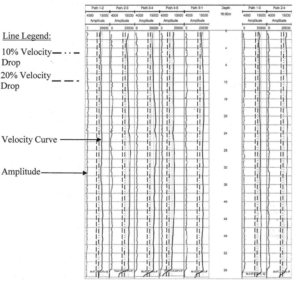
43 Crosshole Sonic Logging
44
45 Gamma Density Logging
46
47 Load Testing of Drilled Shafts gstatic Load Tests - Similar to driven piles - Osterberg Load Cell test gstatnamic test gmust perform caliper logging and NDTs before load testing
48 Osterberg Load Cell Test

49

50 Osterberg Cell gtable 9-11, 9 Table 9-129
 CSL")
51 Cage Centralizers O-cells between two steel plates Instrumentation (strain gages) CSL tubes
52 Statnamic Load Test

53 Statnamic Load Tests
54 Learning Outcomes gat the end of this session, the participant will be able to: - Contrast driven piles and drilled shafts - Compare mobilization of base (tip) and side (shaft) resistance - Describe drilled shaft construction processes - Discuss the need for quality control for drilled shaft construction
55 Any Questions? Any Questions? THE ROAD TO UNDERSTANDING SOILS AND FOUNDATIONS
56 Inspector Qualification Courses
CHAPTER 8 CALCULATION THEORY
 CHAPTER 8 CALCULATION THEORY. Volume 2 CHAPTER 8 CALCULATION THEORY Detailed in this chapter: the theories behind the program the equations and methods that are use to perform the analyses. CONTENTS CHAPTER
INTRODUCTION TO STATIC ANALYSIS PDPI 2013
 INTRODUCTION TO STATIC ANALYSIS PDPI 2013 What is Pile Capacity? When we load a pile until IT Fails what is IT Strength Considerations Two Failure Modes 1. Pile structural failure controlled by allowable
Lesson 25. Static Pile Load Testing, O-cell, and Statnamic. Reference Manual Chapter 18
 Lesson 25 Static Pile Load Testing, O-cell, and Statnamic Reference Manual Chapter 18 STATIC LOAD TESTING Most accurate method to determine static pile capacity Perform at design or construction stage
Deep Foundations 2. Load Capacity of a Single Pile
 Deep Foundations 2 Load Capacity of a Single Pile All calculations of pile capacity are approximate because it is almost impossible to account for the variability of soil types and the differences in the
Drilled Shaft Foundations in Limestone. Dan Brown, P.E., Ph.D. Dan Brown and Associates
 Drilled Shaft Foundations in Limestone Dan Brown, P.E., Ph.D. Dan Brown and Associates Foundation Engineering How we teach our students Fundamental understanding of soil and rock behavior (good!) Focus
TABLE OF CONTENTS CHAPTER TITLE PAGE TITLE PAGE DECLARATION DEDIDATION ACKNOWLEDGEMENTS ABSTRACT ABSTRAK
 TABLE OF CONTENTS CHAPTER TITLE PAGE TITLE PAGE DECLARATION DEDIDATION ACKNOWLEDGEMENTS ABSTRACT ABSTRAK TABLE OF CONTENTS LIST OF TABLE LIST OF FIGURES LIST OF SYMBOLS LIST OF APENDICES i ii iii iv v
PECivilExam.com. Copyright 2015 Pecivilexam.com all rights reserved- E-Book Geotechnical Depth Exam: 80 problems
 PECivilExam.com PE Civil Exam 80- Geotechnical Questions & Answers (pdf Format) For Depth Exam (Evening Session) PE Civil Depth Exam (Evening Session): This practice exam contains 80- Geotechnical questions,
IN SITU TESTING TECHNOLOGY FOR FOUNDATION & EARTHQUAKE ENGINEERING. Wesley Spang, Ph.D., P.E. AGRA Earth & Environmental, Inc.
 IN SITU TESTING TECHNOLOGY FOR FOUNDATION & EARTHQUAKE ENGINEERING Wesley Spang, Ph.D., P.E. AGRA Earth & Environmental, Inc. Portland, Oregon In situ testing of soil, which essentially consists of evaluating
Interpretation of Pile Integrity Test (PIT) Results
 Results") Annual Transactions of IESL, pp. 78-84, 26 The Institution of Engineers, Sri Lanka Interpretation of Pile Integrity Test (PIT) Results H. S. Thilakasiri Abstract: A defect present in a pile will severely
Annual Transactions of IESL, pp. 78-84, 26 The Institution of Engineers, Sri Lanka Interpretation of Pile Integrity Test (PIT) Results H. S. Thilakasiri Abstract: A defect present in a pile will severely
Boreholes. Implementation. Boring. Boreholes may be excavated by one of these methods: 1. Auger Boring 2. Wash Boring 3.
 Implementation Boreholes 1. Auger Boring 2. Wash Boring 3. Rotary Drilling Boring Boreholes may be excavated by one of these methods: 4. Percussion Drilling The right choice of method depends on: Ground
Chapter 12 Subsurface Exploration
 Page 12 1 Chapter 12 Subsurface Exploration 1. The process of identifying the layers of deposits that underlie a proposed structure and their physical characteristics is generally referred to as (a) subsurface
Chapter (11) Pile Foundations
 Pile Foundations") Chapter (11) Introduction Piles are structural members that are made of steel, concrete, or timber. They are used to build pile foundations (classified as deep foundations) which cost more than shallow
Chapter (11) Introduction Piles are structural members that are made of steel, concrete, or timber. They are used to build pile foundations (classified as deep foundations) which cost more than shallow
OP-023. INTERPRETATION OF INSTRUMENTED TEST PILE RESULT
 INTERPRETATION OF INSTRUMENTED TEST PILE RESULT Page 1 of 9 WORK INSTRUCTIONS FOR ENGINEERS GSJ Compiled by : Checked by KYW : LSS Approved by : OP-23. INTERPRETATION OF INSTRUMENTED TEST PILE RESULT INTERPRETATION
Piles Capacity Reference Manual
 Piles Capacity Reference Manual hetge hetge geotechnics on the go Piles Capacity Reference Manual January 3, 2013 Version: PC-1.3.130103 hetge LLC Moscow Virginia Istanbul E info@hetge.com W www.hetge.com
INTI COLLEGE MALAYSIA
 EGC373 (F) / Page 1 of 5 INTI COLLEGE MALAYSIA UK DEGREE TRANSFER PROGRAMME INTI ADELAIDE TRANSFER PROGRAMME EGC 373: FOUNDATION ENGINEERING FINAL EXAMINATION : AUGUST 00 SESSION This paper consists of
AN ABSTRACT OF THE THESIS OF
 AN ABSTRACT OF THE THESIS OF Nasim Adami for the degree of Master of Science in Civil Engineering presented on October 28, 213. Title: Development of an ACIP Pile-Specific Load-Displacement Model. Abstract
3-BEARING CAPACITY OF SOILS
 3-BEARING CAPACITY OF SOILS INTRODUCTION The soil must be capable of carrying the loads from any engineered structure placed upon it without a shear failure and with the resulting settlements being tolerable
Bearing Capacity of Soils in Deep Foundations Course No. CE0148 PDH: 5
 Bearing Capacity of Soils in Deep Foundations Course No. CE0148 PDH: 5 ** PLEASE NOTE: THIS COURSE IS A SUBSECTION OF COURSE # CE0009 ** In order to obtain credit for this course, the following steps listed
ENCE 3610 Soil Mechanics. Site Exploration and Characterisation Field Exploration Methods
 ENCE 3610 Soil Mechanics Site Exploration and Characterisation Field Exploration Methods Geotechnical Involvement in Project Phases Planning Design Alternatives Preparation of Detailed Plans Final Design
SHEET PILE WALLS. Mehdi Mokhberi Islamic Azad University
 SHEET PILE WALLS Mehdi Mokhberi Islamic Azad University Lateral Support In geotechnical engineering, it is often necessary to prevent lateral soil movements. Tie rod Anchor Sheet pile Cantilever retaining
PILE LOAD TEST IN OLD ALLUVIUM
 An evening talk organized by GeoSS PILE LOAD TEST IN OLD ALLUVIUM Wong Kai Sin 25 August 2016 1 PILE LOAD TEST IN OLD ALLUVIUM 1.Should we accept or reject the test results? 2.What are the expected unit
LRFD GEOTECHNICAL IMPLEMENTATION
 LRFD GEOTECHNICAL IMPLEMENTATION Ching-Nien Tsai, P.E. LADOTD Pavement and Geotechnical Services In Conjunction with LTRC WHY LRFD FHWA deadline - October 2007 LRFD is a better method Risk is quantified
Development of Preliminary Load and Resistance Factor Design of Drilled Shafts in Iowa
 InTrans Project Reports Institute for Transportation 10-2014 Development of Preliminary Load and Factor Design of Drilled Shafts in Iowa Kam W. Ng Iowa State University Sri Sritharan Iowa State University,
CPT Guide 5 th Edition. CPT Applications - Deep Foundations. Gregg Drilling & Testing, Inc. Dr. Peter K. Robertson Webinar # /2/2013
 Gregg Drilling & Testing, Inc. Site Investigation Experts CPT Applications - Deep Foundations Dr. Peter K. Robertson Webinar #6 2013 CPT Guide 5 th Edition Robertson & Cabal (Robertson) 5 th Edition 2012
Theory of Shear Strength
 SKAA 1713 SOIL MECHANICS Theory of Shear Strength Prepared by, Dr. Hetty 1 SOIL STRENGTH DEFINITION Shear strength of a soil is the maximum internal resistance to applied shearing forces The maximum or
Engineeringmanuals. Part2
 Engineeringmanuals Part2 Engineering manuals for GEO5 programs Part 2 Chapter 1-12, refer to Engineering Manual Part 1 Chapter 13. Pile Foundations Introduction... 2 Chapter 14. Analysis of vertical load-bearing
GEOTECHNICAL ENGINEERING II. Subject Code : 06CV64 Internal Assessment Marks : 25 PART A UNIT 1
 GEOTECHNICAL ENGINEERING II Subject Code : 06CV64 Internal Assessment Marks : 25 PART A UNIT 1 1. SUBSURFACE EXPLORATION 1.1 Importance, Exploration Program 1.2 Methods of exploration, Boring, Sounding
IAEA SAFETY STANDARDS Geotechnical Aspects of Site Evaluation and Foundations in NPPs, NS-G-3.6
 IAEA SAFETY STANDARDS Geotechnical Aspects of Site Evaluation and Foundations in NPPs, NS-G-3.6 Regional Workshop on Volcanic, Seismic, and Tsunami Hazard Assessment Related to NPP Siting Activities and
Chapter (5) Allowable Bearing Capacity and Settlement
 Allowable Bearing Capacity and Settlement") Chapter (5) Allowable Bearing Capacity and Settlement Introduction As we discussed previously in Chapter 3, foundations should be designed for both shear failure and allowable settlement. So the allowable
Chapter (5) Allowable Bearing Capacity and Settlement Introduction As we discussed previously in Chapter 3, foundations should be designed for both shear failure and allowable settlement. So the allowable
NEW DOWN-HOLE PENETROMETER (DHP-CIGMAT) FOR CONSTRUCTION APPLICATIONS
 FOR CONSTRUCTION APPLICATIONS") NEW DOWN-HOLE PENETROMETER (DHP-CIGMAT) FOR CONSTRUCTION APPLICATIONS 1 2 C. Vipulanandan 1, Ph.D., M. ASCE and Omer F. Usluogullari 2 Chairman, Professor, Director of Center for Innovative Grouting Materials
NEW DOWN-HOLE PENETROMETER (DHP-CIGMAT) FOR CONSTRUCTION APPLICATIONS 1 2 C. Vipulanandan 1, Ph.D., M. ASCE and Omer F. Usluogullari 2 Chairman, Professor, Director of Center for Innovative Grouting Materials
ADVANCED SOIL MECHANICS FINAL EXAM (TAKE HOME):DUE THURSDAY, DECEMBER 19, 6PM.
:DUE THURSDAY, DECEMBER 19, 6PM.") 14.531 ADVANCED SOIL MECHANICS FINAL EXAM (TAKE HOME):DUE THURSDAY, DECEMBER 19, 2013 @ 6PM. Problem #1. Field load tests on strip footings yielded the test data provided below in Figure 1 and Table 1
14.531 ADVANCED SOIL MECHANICS FINAL EXAM (TAKE HOME):DUE THURSDAY, DECEMBER 19, 2013 @ 6PM. Problem #1. Field load tests on strip footings yielded the test data provided below in Figure 1 and Table 1
This document downloaded from vulcanhammer.net vulcanhammer.info Chet Aero Marine
 This document downloaded from vulcanhammer.net vulcanhammer.info Chet Aero Marine Don t forget to visit our companion site http://www.vulcanhammer.org Use subject to the terms and conditions of the respective
Cavity Expansion Methods in Geomechanics
 Cavity Expansion Methods in Geomechanics by Hai-Sui Yu School of Civil Engineering, University of Nottingham, U. K. KLUWER ACADEMIC PUBLISHERS DORDRECHT / BOSTON / LONDON TABLE OF CONTENTS Foreword Preface
Engineer. Engineering. Engineering. (in-ja-neer ) A person trained and skilled in any of the various branches of engineering: a civil engineer
 A person trained and skilled in any of the various branches of engineering: a civil engineer") Engineer (in-ja-neer ) A person trained and skilled in any of the various branches of engineering: a civil engineer (Random House Webster s College Dictionary, 1991) CE100 Introduction to Civil Geotechnical
Engineer (in-ja-neer ) A person trained and skilled in any of the various branches of engineering: a civil engineer (Random House Webster s College Dictionary, 1991) CE100 Introduction to Civil Geotechnical
Axially Loaded Piles
 Axially Loaded Piles 1 t- Curve Method using Finite Element Analysis The stress-strain relationship for an axially loaded pile can be described through three loading mechanisms: axial deformation in the
!!!!!! Piles Capacity Reference Manual
 Piles Capacity Reference Manual Foreword July 26, 2014 Piles Capacity is simply the pocket calculator for deep foundation designers dealing with pile bearing capacity of cast-in-place bored piles (also
The Bearing Capacity of Soils. Dr Omar Al Hattamleh
 The Bearing Capacity of Soils Dr Omar Al Hattamleh Example of Bearing Capacity Failure Omar Play the move of bearing Capacity failure The Philippine one Transcona Grain Silos Failure - Canada The Bearing
KDOT Geotechnical Manual Edition. Table of Contents
 KDOT Geotechnical Manual 2007 Edition The KDOT Geotechnical Manual is available two volumes. Both volumes are very large electronic (pdf) files which may take several minutes to download. The table of
Conventional Field Testing & Issues (SPT, CPT, DCPT, Geophysical methods)
") Conventional Field Testing & Issues (SPT, CPT, DCPT, Geophysical methods) Ajanta Sachan Assistant Professor Civil Engineering IIT Gandhinagar Conventional Field Testing 1 Field Test: In-situ shear strength
Conventional Field Testing & Issues (SPT, CPT, DCPT, Geophysical methods) Ajanta Sachan Assistant Professor Civil Engineering IIT Gandhinagar Conventional Field Testing 1 Field Test: In-situ shear strength
10. GEOTECHNICAL EXPLORATION PROGRAM
 Geotechnical site investigations should be conducted in multiple phases to obtain data for use during the planning and design of the tunnel system. Geotechnical investigations typically are performed in
CHEN YUE. Bachelor of Science in Civil Engineering
 INVESTIGATION OF PREDICTION METHODS FOR BEARING CAPACITY OF PILES By CHEN YUE Final Year Project Report submitted in partial fulfillment of the requirement of the Degree of Bachelor of Science in Civil
In-class Exercise. Problem: Select load factors for the Strength I and Service I Limit States for the. Loading Diagram for Student Exercise
 In-class Exercise Problem: Select load factors for the Strength I and Service I Limit States for the problem illustrated below. Loading Diagram for Student Exercise For this exercise, complete the following
User Guide for FB-Deep F.C. Townsend
 User Guide or FB-Deep F.C. Townsend Intro: FB-Deep (ormerly SHAFT-SPT) is a combination o SHAFT 98, which uses the FHWA O Neill & Reese method or drilled shats and intermediate geomaterials, and SPT97,
Numerical modelling of tension piles
 Numerical modelling of tension piles S. van Baars Ministry of Public Works, Utrecht, Netherlands W.J. van Niekerk Ballast Nedam Engineering, Amstelveen, Netherlands Keywords: tension piles, shaft friction,
Measurement of effective stress shear strength of rock
 Measurement of effective stress shear strength of rock R. A. Failmezger, P.E., F. ASCE In-Situ Soil Testing, L.C., Lancaster, Virginia USA D. J. White, Ph. D., P.E. Iowa State University, Ames, Iowa USA
7. Foundation and Slope Stability
 The Asian Nuclear Safety Network 7. Foundation and Slope Stability (SER 2.5.4 & 2.5.5) Taek-Mo SHIM k147stm@kins.re.kr Korea Institute of Nuclear Safety Structural Systems and Site Evaluation Department
S E C T I O N 1 2 P R O D U C T S E L E C T I O N G U I D E - H E L I C A L S C R E W P I L E F O U N D A T I O N S
 1. P R O D U C T S E L E C T I O N G U I D E - H E L I C A L S C R E W P I L E F O U N D A T I O N S Helical foundation pile includes a lead and extension(s). The lead section is made of a central steel
Reinforced Soil Structures Reinforced Soil Walls. Prof K. Rajagopal Department of Civil Engineering IIT Madras, Chennai
 Geosynthetics and Reinforced Soil Structures Reinforced Soil Walls continued Prof K. Rajagopal Department of Civil Engineering IIT Madras, Chennai e-mail: gopalkr@iitm.ac.inac in Outline of the Lecture
HKIE-GD Workshop on Foundation Engineering 7 May Shallow Foundations. Dr Limin Zhang Hong Kong University of Science and Technology
 HKIE-GD Workshop on Foundation Engineering 7 May 2011 Shallow Foundations Dr Limin Zhang Hong Kong University of Science and Technology 1 Outline Summary of design requirements Load eccentricity Bearing
water proofing will relatively long time fully completed) be provided 10 storey building (15x25m) original GWT position 1 sat = 20 kn/m 3
 be provided 10 storey building (15x25m) original GWT position 1 sat = 20 kn/m 3") P1 Question: An excavation will be made for a ten storey 15x25 m building. Temporary support of earth pressure and water pressure will be made by deep secant cantilever pile wall. The gross pressure due
P1 Question: An excavation will be made for a ten storey 15x25 m building. Temporary support of earth pressure and water pressure will be made by deep secant cantilever pile wall. The gross pressure due
Liquefaction Induced Negative Skin Friction from Blast-induced Liquefaction Tests with Auger-cast Piles
 6 th International Conference on Earthquake Geotechnical Engineering 1-4 November 2015 Christchurch, New Zealand Liquefaction Induced Negative Skin Friction from Blast-induced Liquefaction Tests with Auger-cast
Guidelines on Foundation Loading and Deformation Due to Liquefaction Induced Lateral Spreading
 Guidelines on Foundation Loading and Deformation Due to Liquefaction Induced Lateral Spreading February, 2011 1 INTRODUCTION Past earthquakes offer many examples of bridges that either collapsed or incurred
ADSC Research Project Update: Rock Sockets in the Southeastern U.S.
 ADSC Research Project Update: Rock Sockets in the Southeastern U.S. W. Robert Thompson, III, P.E., D.GE, M.ASCE 1 ABSTRACT The bearing capacity of drilled shafts in rock has traditionally been assessed
Transmission Line Design Structures & Foundations TADP 549
 Transmission Line Design Structures & Foundations TADP 549 Steel Poles - Direct Embedment Foundations - Point of Fixity Presentation 6.3 Dr. Prasad Yenumula Transmission & Distribution Program Reference
Geotechnical Engineering Study, Conifer Senior High School Football Field Improvements, Conifer, Colorado
 2390 South Lipan Street Denver, CO 80223 phone: (303) 742-9700 fax: (303) 742-9666 email: kadenver@kumarusa.com www.kumarusa.com Office Locations: Denver (HQ), Colorado Springs, Fort Collins, and Frisco,
LRFD Application in Driven Piles (Recent Development in Pavement & Geotech at LTRC)
") LRFD Application in Driven Piles (Recent Development in Pavement & Geotech at LTRC) 2007 Louisiana Transportation Engineering Conference February 12, 2007 Sungmin Sean Yoon, Ph. D., P.E. and Murad Abu-Farsakh,
LRFD Application in Driven Piles (Recent Development in Pavement & Geotech at LTRC) 2007 Louisiana Transportation Engineering Conference February 12, 2007 Sungmin Sean Yoon, Ph. D., P.E. and Murad Abu-Farsakh,
EN Eurocode 7. Section 3 Geotechnical Data Section 6 Spread Foundations. Trevor L.L. Orr Trinity College Dublin Ireland.
 EN 1997 1: Sections 3 and 6 Your logo Brussels, 18-20 February 2008 Dissemination of information workshop 1 EN 1997-1 Eurocode 7 Section 3 Geotechnical Data Section 6 Spread Foundations Trevor L.L. Orr
B-1 BORE LOCATION PLAN. EXHIBIT Drawn By: 115G BROOKS VETERINARY CLINIC CITY BASE LANDING AND GOLIAD ROAD SAN ANTONIO, TEXAS.
 N B-1 SYMBOLS: Exploratory Boring Location Project Mngr: BORE LOCATION PLAN Project No. GK EXHIBIT Drawn By: 115G1063.02 GK Scale: Checked By: 1045 Central Parkway North, Suite 103 San Antonio, Texas 78232
Manual on Subsurface Investigations National Highway Institute Publication No. FHWA NHI Federal Highway Administration Washington, DC
 Manual on Subsurface Investigations National Highway Institute Publication No. FHWA NHI-01-031 Federal Highway Administration Washington, DC Geotechnical Site Characterization July 2001 by Paul W. Mayne,
Liquefaction and Foundations
 Liquefaction and Foundations Amit Prashant Indian Institute of Technology Gandhinagar Short Course on Seismic Design of Reinforced Concrete Buildings 26 30 November, 2012 What is Liquefaction? Liquefaction
SITE INVESTIGATION 1
 SITE INVESTIGATION 1 Definition The process of determining the layers of natural soil deposits that will underlie a proposed structure and their physical properties is generally referred to as site investigation.
SELMON EXPRESSWAY, TAMPA: CASE HISTORY OF DRILLED SHAFT DESIGN FOR EXTREME VARIABILITY
 SELMON EXPRESSWAY, TAMPA: CASE HISTORY OF DRILLED SHAFT DESIGN FOR EXTREME VARIABILITY David S. Graham, Dan Brown and Associates, PC, Chattanooga, Tennessee Steven D. Dapp, Dan Brown and Associates, PC,
Predicting Settlement and Stability of Wet Coal Ash Impoundments using Dilatometer Tests
 Predicting Settlement and Stability of Wet Coal Ash Impoundments using Dilatometer Tests Chris Hardin, P.E. CH2M Hill, Charlotte, North Carolina, E-mail: Chris.Hardin@ch2m.com Roger Failmezger, P.E., F.
Background. Valley fills Sites in the Area. Construction over Mine Spoil Fills
 Construction over Mine Spoil Fills Wayne A. Karem, PhD, PE, PG, D.GE 2014 KSPE Annual Conference Background Strip mining; mountaintop and contour mining Creates huge quantities of mine spoil The mine spoil
Introduction to Soil Mechanics
 Introduction to Soil Mechanics Sela Sode and Colin Jones WILEY Blackwell Contents Preface Dedication and Acknowledgments List of Symbols Soil Structure 1.1 Volume relationships 1.1.1 Voids ratio (e) 1.1.2
OP-13. PROCEDURES FOR DESIGN OF EMBANKMENT
 Page 1 of 8 WORK INSTRUCTIONS FOR ENGINEERS TYC Compiled by : LSS Checked by : GSS Approved by : OP-13. PROCEDURES FOR DESIGN OF EMBANKMENT Page of 8 13.0 13.1. OVERALL PROCEDURES This section will briefly
(THIS IS ONLY A SAMPLE REPORT OR APPENDIX OFFERED TO THE USERS OF THE COMPUTER PROGRAM
 C A U T I O N!! (THIS IS ONLY A SAMPLE REPORT OR APPENDIX OFFERED TO THE USERS OF THE COMPUTER PROGRAM EQLique&Settle2. THE AUTHOR IS HEREBY RELEASED OF ANY LIABILITY FOR ANY INCORRECT USE OF THIS SAMPLE
Theory of Shear Strength
 MAJ 1013 ADVANCED SOIL MECHANICS Theory of Shear Strength Prepared by, Dr. Hetty 1 Strength of different materials Steel Concrete Soil Tensile strength Compressive strength Shear strength Complex behavior
LRFD Calibration of Axially-Loaded Concrete Piles Driven into Louisiana Soils
 LRFD Calibration of Axially-Loaded Concrete Piles Driven into Louisiana Soils Louisiana Transportation Conference February 10, 2009 Sungmin Sean Yoon, Ph. D., P.E. (Presenter) Murad Abu-Farsakh, Ph. D.,
Analysis of a single pile settlement
 Engineering manual No. 14 Updated: 06/2018 Analysis of a single pile settlement Program: Pile File: Demo_manual_14.gpi The objective of this engineering manual is to explain the application of the GEO
Module 1 : Site Exploration and Geotechnical Investigation
 Objectives In this section you will learn the following Displacement borings Wash boring Auger boring Rotary drilling Percussion drilling Continuous sampling Boring methods of exploration The boring methods
SOIL INVESTIGATION REPORT. PROPOSED HOUSING DEVELOPMENT PROJECT Coral Spring, Trelawny, Jamaica.
 SOIL INVESTIGATION REPORT PROPOSED HOUSING DEVELOPMENT PROJECT Coral Spring, Trelawny, Jamaica. Prepared for: FCS Consultants 7a Barbados Avenue Kingston 5, Jamaica Prepared by: NHL Engineering Limited
 R-1 Conveyor Relocation Project Legend 0 500 1000 1500 ft. This map is a user generated static output from an Internet mapping site and is for general reference only. Data layers that appear on this map
Collapsible Soils Definitions
 Collapsible Soils Definitions Collapsible soils are also known as metastable soils. They are unsaturated soils that undergo a large volume change upon saturation. The sudden and usually large volume change
MEDAT-2: Some Geotechnical Opportunities. Site Characterization -- Opportunities. Down-hole CPT & vane (Fugro)
") MEDAT-2: Some Geotechnical Opportunities Ross W. Boulanger Department of Civil & Environmental Engineering University of California Davis, California 95616-5294 rwboulanger@ucdavis.edu Presentation for
MEDAT-2: Some Geotechnical Opportunities Ross W. Boulanger Department of Civil & Environmental Engineering University of California Davis, California 95616-5294 rwboulanger@ucdavis.edu Presentation for
ON THE PREDICTION OF EXPERIMENTAL RESULTS FROM TWO PILE TESTS UNDER FORCED VIBRATIONS
 Transactions, SMiRT-24 ON THE PREDICTION OF EXPERIMENTAL RESULTS FROM TWO PILE TESTS UNDER FORCED VIBRATIONS 1 Principal Engineer, MTR & Associates, USA INTRODUCTION Mansour Tabatabaie 1 Dynamic response
Computers and Geotechnics
 Computers and Geotechnics xxx (29) xxx xxx Contents lists available at ScienceDirect Computers and Geotechnics journal homepage: www.elsevier.com/locate/compgeo Simulation of the progressive failure of
R.M.HARW & ASSOCIATES LTD. GEOTECHNICAL INVESTIGATION PROPOSED BRIDGE SITE. HELAVA CREEKl MILE MACKENZIE HIGHWAY E-2510 OCTOBER 16, 1973
 El R.M.HARW & ASSOCIATES LTD. GEOTECHNICAL INVESTIGATION PROPOSED BRIDGE SITE HELAVA CREEKl MILE 616.4 MACKENZIE HIGHWAY E-2510 OCTOBER 16, 1973 R,M,HARDV & ASSOCIATES LTD. CONSULTING ENGINEERING & TESTING
Cyclic Behavior of Sand and Cyclic Triaxial Tests. Hsin-yu Shan Dept. of Civil Engineering National Chiao Tung University
 Cyclic Behavior of Sand and Cyclic Triaxial Tests Hsin-yu Shan Dept. of Civil Engineering National Chiao Tung University Causes of Pore Pressure Buildup due to Cyclic Stress Application Stress are due
Pile-Soil Interaction in Unsaturated Soil Conditions
 University of New Hampshire University of New Hampshire Scholars' Repository Honors Theses and Capstones Student Scholarship Spring 2014 Pile-Soil Interaction in Unsaturated Soil Conditions Megan Hamilton
Implementation of Pile Setup in the LRFD Design of Driven Piles in Louisiana
 Implementation of Pile Setup in the LRFD Design of Driven Piles in Louisiana Md. Nafiul Haque (Ph.D. Candidate) Murad Y. Abu-Farsakh, Ph.D., P.E. March 1, 2016 Louisiana Transportation Conference OUTLINE
D1. A normally consolidated clay has the following void ratio e versus effective stress σ relationship obtained in an oedometer test.
 (d) COMPRESSIBILITY AND CONSOLIDATION D1. A normally consolidated clay has the following void ratio e versus effective stress σ relationship obtained in an oedometer test. (a) Plot the e - σ curve. (b)
Modified Dry Mixing (MDM) a new possibility in Deep Mixing
 a new possibility in Deep Mixing") Modified Dry Mixing (MDM) a new possibility in Deep Mixing Hercules Geo-Trans 2004 1 Structure of presentation 1. The MDM process 2. The MDM system new possibilities 3. Major advantages 4. Field tests
Modified Dry Mixing (MDM) a new possibility in Deep Mixing Hercules Geo-Trans 2004 1 Structure of presentation 1. The MDM process 2. The MDM system new possibilities 3. Major advantages 4. Field tests
Use of RMR to Improve Determination of the Bearing Resistance of Rock
 Creating Value Delivering Solutions Use of RMR to Improve Determination of the Bearing Resistance of Rock Scott Zang, P.E. Michael Baker Jr., Inc. ASD Design Q v allowable is a presumptive allowable bearing
TRANSPORTATION RESEARCH BOARD. Static and Seismic Design of Piles for Downdrag. Thursday, October 4, :00-3:30 PM ET
 TRANSPORTATION RESEARCH BOARD Static and Seismic Design of Piles for Downdrag Thursday, October 4, 2018 2:00-3:30 PM ET The Transportation Research Board has met the standards and requirements of the Registered
Cone Penetration Testing in Geotechnical Practice
 Cone Penetration Testing in Geotechnical Practice Table Of Contents: LIST OF CONTENTS v (4) PREFACE ix (2) ACKNOWLEDGEMENTS xi (1) SYMBOL LIST xii (4) CONVERSION FACTORS xvi (6) GLOSSARY xxii 1. INTRODUCTION
Chapter 7 GEOMECHANICS
 Chapter 7 Final SCDOT GEOTECHNICAL DESIGN MANUAL August 2008 Table of Contents Section Page 7.1 Introduction...7-1 7.2 Geotechnical Design Approach...7-1 7.3 Geotechnical Engineering Quality Assurance...7-2
Bored Sockets in weathered Basalt
 Bored Sockets in weathered Basalt L. Maertens Manager Engineering Department Besix, Belgium Associate Professor Catholic University Leuven Keywords: sockets, open-end piles, tensile piles, basalt ABSTRACT:
SHEAR STRENGTH OF SOIL
 SHEAR STRENGTH OF SOIL Necessity of studying Shear Strength of soils : Soil failure usually occurs in the form of shearing along internal surface within the soil. Shear Strength: Thus, structural strength
STUDY OF THE BEHAVIOR OF PILE GROUPS IN LIQUEFIED SOILS
 STUDY OF THE BEHAVIOR OF PILE GROUPS IN LIQUEFIED SOILS Shin-Tower Wang 1, Luis Vasquez 2, and Lymon C. Reese 3, Honorary Member,, ASCE ABSTRACT : 1&2 President & Project Manager, Ensoft, Inc. Email: ensoft@ensoftinc.com
Introduction to Geotechnical Engineering. ground
 Introduction to Geotechnical Engineering ground 1 Typical Geotechnical Project Geo-Laboratory ~ for testing soil properties Design Office ~ for design & analysis construction site 2 Shallow Foundations
Gotechnical Investigations and Sampling
 Gotechnical Investigations and Sampling Amit Prashant Indian Institute of Technology Gandhinagar Short Course on Geotechnical Investigations for Structural Engineering 12 14 October, 2017 1 Purpose of
BACKGROUND AND INTRODUCTION
 WAVE MECHANICS As applied to pile testing 1 BACKGROUND AND INTRODUCTION Wave Mechanics 2 1 HISTORIC TOOLS AND MATERIALS Timber piles Drop Hammers 10 Days for the Romans to build the bridge over the Rhine
THE STRUCTURAL DESIGN OF PILE FOUNDATIONS BASED ON LRFD FOR JAPANESE HIGHWAYS
 THE STRUCTURAL DESIGN OF PILE FOUNDATIONS BASED ON LRFD FOR JAPANESE HIGHWAYS Hideaki Nishida 1,Toshiaki Nanazawa 2, Masahiro Shirato 3, Tetsuya Kohno 4, and Mitsuaki Kitaura 5 Abstract One of the motivations
CHAPTER 17 DEEP FOUNDATION III: DRILLED PIER FOUNDATIONS 17.1 INTRODUCTION 17.2 TYPES OF DRILLED PIERS
 CHAPTER 17 DEEP FOUNDATION III: DRILLED PIER FOUNDATIONS 17.1 INTRODUCTION Chapter 15 dealt with piles subjected to vertical loads and Chapter 16 with piles subjected to lateral loads. Drilled pier foundations,
Evaluation of Unknown Foundations
 University of South Florida Scholar Commons Graduate Theses and Dissertations Graduate School 3-27-2007 Evaluation of Unknown Foundations Ronald W. Florkowski University of South Florida Follow this and
This is what we will talk about today.
 This is what we will talk about today. 1. INTRODUCTION 2. SINGLE DEGREE OF FREEDOM, DAMPED, FORCED SYSTEMS 3. FOUNDATIONS ON ELASTIC SOILS 4. WAVE TRANSMISSION, ATTENUATION, AND ISOLATION 5. EVALUATION
Geotechnical Indications Of Eastern Bypass Area In Port Harcourt, Niger Delta
 Geotechnical Indications Of Eastern Bypass Area In Port Harcourt, Niger Delta Warmate Tamunonengiyeofori Geostrat International Services Limited, Rivers State, Nigeria www.geostratinternational.com info@geostratinternational.com,
Chapter 7: Settlement of Shallow Foundations
 Chapter 7: Settlement of Shallow Foundations Introduction The settlement of a shallow foundation can be divided into two major categories: (a) elastic, or immediate settlement and (b) consolidation settlement.
SOIL MECHANICS: palgrave. Principles and Practice. Graham Barnes. macmiiian THIRD EDITION
 SOIL MECHANICS: Principles and Practice THIRD EDITION Graham Barnes palgrave macmiiian 'running Contents Preface xii Fine soil 19 List of symbols xiv Mass structure 21 Note on units xix Degree of weathering