GEOTECHNICAL INVESTIGATION FUTURE ATHLETIC COMPLEX AT PALOMAR COLLEGE 1140 WEST MISSION ROAD SAN MARCOS, CALIFORNIA. Prepared for:
|
|
|
- Ann Banks
- 5 years ago
- Views:
Transcription
1 GEOTECHNICAL INVESTIGATION FUTURE ATHLETIC COMPLEX AT PALOMAR COLLEGE 1140 WEST MISSION ROAD SAN MARCOS, CALIFORNIA Prepared for: PALOMAR COMMUNITY COLLEGE DISTRICT 1140 WEST MISSION ROAD SAN MARCOS, CALIFORNIA Prepared by: CONSTRUCTION TESTING & ENGINEERING, INC MONTIEL ROAD, SUITE 115 ESCONDIDO, CALIFORNIA CTE JOB NO.: G MARCH 7, 2016
2 TABLE OF CONTENTS 1.0 INTRODUCTION AND SCOPE OF SERVICES Introduction Scope of Services SITE DESCRIPTION FIELD INVESTIGATION AND LABORATORY TESTING Field Investigation Laboratory Testing GEOLOGY General Setting Geologic Conditions Quaternary Previously Placed Fill Quaternary Undocumented Fill Quaternary Young Alluvial Flood Plain Deposits Residual Soil Cretaceous Tonalite Metasedimentary and Metavolcanic Rock Undivided Groundwater Conditions Geologic Hazards Surface Fault Rupture Local and Regional Faulting Historic Seismicity Liquefaction and Seismic Settlement Evaluation Tsunamis and Seiche Evaluation Flooding Landsliding Compressible and Expansive Soils Corrosive Soils CONCLUSIONS AND RECOMMENDATIONS General Site Preparation Bedrock Terrain Undocumented Fill Soil and Residual Soil Terrain General Site Excavation Fill Placement and Compaction Fill Materials Temporary Construction Slopes Foundations and Slab Recommendations Shallow Spread Foundations Foundation Settlement Foundation Setback Interior Concrete Slabs-On-Grade Seismic Design Criteria Lateral Resistance and Earth Pressures... 27
3 5.10 Exterior Flatwork Vehicular Pavements Drainage Slopes Plan Review Construction Observation LIMITATIONS OF INVESTIGATION FIGURES FIGURE 1 FIGURE 2 FIGURE 2A FIGURE 3 FIGURE 4 FIGURE 4A FIGURE 5 FIGURE 6 SITE LOCATION MAP GEOLOGIC/ EXPLORATION LOCATION MAP GEOLOGIC/ EXPLORATION LOCATION MAP REGIONAL GEOLOGIC MAP CROSS SECTION A-A' CROSS SECTION B-B' and C-C' REGIONAL FAULT AND SEISMICITY MAP CONCEPTUAL RETAINING WALL DRAINAGE DETAIL APPENDICES APPENDIX A APPENDIX B APPENDIX C APPENDIX D APPENDIX E REFERENCES FIELD EXPLORATION METHODS LOGS LABORATORY METHODS AND RESULTS STANDARD GRADING SPECIFICATIONS GEOPHYSICAL TESTING
4 Geotechnical Investigation Page 1 Future Athletic Complex at Palomar College 1140 West Mission Road, San Marcos, California March 7, 2016 CTE Job No.: G 1.0 INTRODUCTION AND SCOPE OF SERVICES 1.1 Introduction This report presents the results of the geotechnical investigation, performed by Construction Testing and Engineering, Inc. (CTE), and provides preliminary conclusions and recommendations for the proposed Future Athletic Complex at the existing Palomar Community College campus in San Marcos, California. This investigation was performed in general accordance with the terms of CTE proposal G-3538, dated August 6, CTE understands that the proposed improvements include a football stadium, softball field, practice field, two swimming pools, tennis courts, volleyball courts, spectator stands, Kinesiology & Training Center, and ancillary structures. Other improvements are anticipated to consist of new parking lots throughout the complex area, a plaza, landscaping, flatwork, and utilities. Preliminary recommendations for excavations, site preparation, fill placement, and foundation design for the proposed improvements are presented herein. CTE s understanding of the proposed improvements is based upon conceptual plans that lack topography and detailed elevations and/or building locations. Therefore, the exploration locations are based upon extrapolation from the conceptual plans. As such, CTE should review additional project plans as they are developed. \\Esc_server\projects\ G\Rpt_Geotechnical.doc
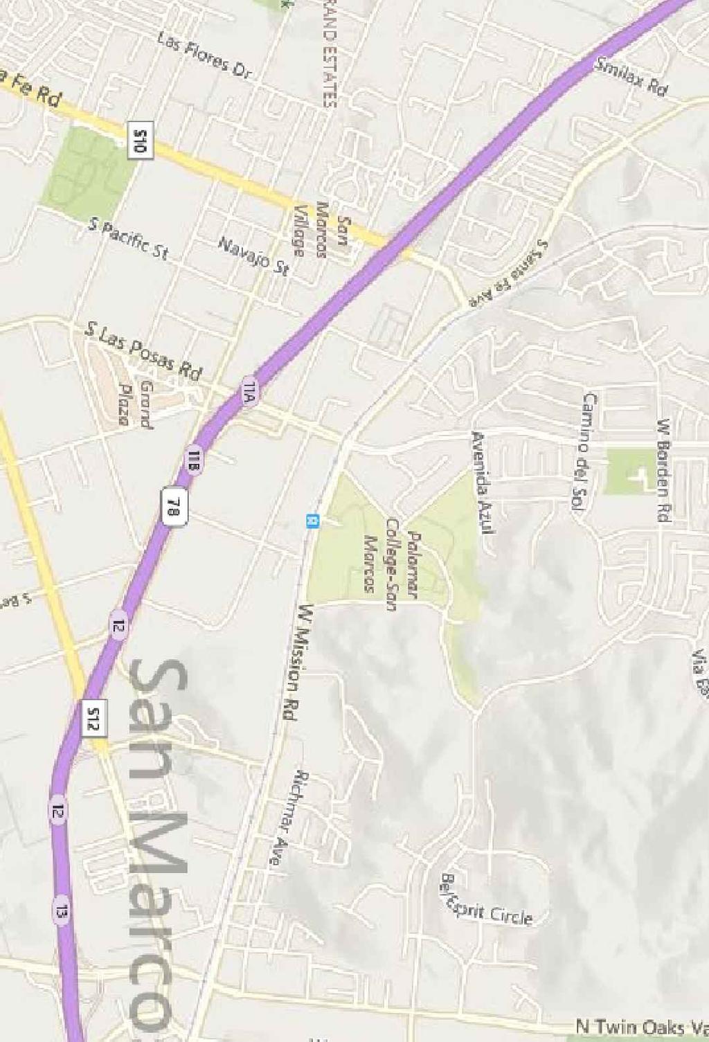
5 Geotechnical Investigation Page 2 Future Athletic Complex at Palomar College 1140 West Mission Road, San Marcos, California March 7, 2016 CTE Job No.: G Attached appendices include: Appendix A, References; Appendix B, Boring Logs; Appendix C, Laboratory Test Results; Appendix D, Standard Specifications for Grading; and, Appendix E, Geophysical Survey. 1.2 Scope of Services The scope of services provided included: Review of referenced geologic and soils reports. Coordination of utility mark-out and location for Underground Services Alert (USA) and a private utility locating company. Obtaining a San Diego County Department of Environmental Health (DEH) Boring Permit. Performing 10 seismic traverses that include eight multi-channel analyses of surface wave (MASW) lines and two seismic refraction lines. Excavation of exploratory borings and soil sampling utilizing a truck-mounted drill rig and limited-access manually advanced augers. Laboratory testing of selected soil samples. Description of the geology and evaluation of potential geologic hazards. Engineering and geologic analysis. Preparation of this summary report. 2.0 SITE DESCRIPTION The proposed improvement area is located at 1140 West Mission Road on the campus of Palomar Community College in San Marcos, California (Figure 1). The improvement area is bounded to the south by Comet Circle, to the east by Borden Road, to the north by undeveloped land, and to the west by existing campus buildings and improvements. The general layout of the subject site and proposed improvements is shown on Figures 2 and 2A. The proposed improvements are to be constructed throughout the northeastern portion of the existing campus in an area that currently \\Esc_server\projects\ G\Rpt_Geotechnical.doc
6 Geotechnical Investigation Page 3 Future Athletic Complex at Palomar College 1140 West Mission Road, San Marcos, California March 7, 2016 CTE Job No.: G supports Student Parking Lot #9, Staff Parking Lot #8, a recently constructed (new) baseball field, utilities, maintenance buildings, and other ancillary structures. Based on the recent reconnaissance and review of area topography, the improvement area is located at the confluence of south and southwest descending drainages. Improvement area elevations range from approximately 680 feet above mean sea level (msl) in the northern portion of the site to approximately 627 feet above msl to the southwest. 3.0 FIELD INVESTIGATION AND LABORATORY TESTING 3.1 Field Investigation CTE conducted field investigation on January 8, 11, and 12, 2016, which included visual reconnaissance and excavation of 60 exploratory borings in accessible and limited access areas. The borings were excavated with a CME-75 truck-mounted drill rig equipped with eight-inch-diameter, hollow-stem augers that extended to a maximum depth of approximately 25.2 feet below the ground surface (bgs) in Boring B-18. Due to limited access, explorations B-6, B-27, B-41, B-42, and B-43 were excavated utilizing a manually operated three-inch diameter auger to a maximum depth of approximately 4.0 feet bgs in Boring B-43. Bulk and relatively undisturbed samples were collected from the cuttings, and by driving Standard Penetration Test and Modified California samplers. The soils were logged in the field by a CTE Certified Engineering Geologist and were visually classified in general accordance with the Unified Soil Classification System. The field descriptions have been modified, where appropriate, to reflect laboratory test results. Boring logs, including \\Esc_server\projects\ G\Rpt_Geotechnical.doc
7 Geotechnical Investigation Page 4 Future Athletic Complex at Palomar College 1140 West Mission Road, San Marcos, California March 7, 2016 CTE Job No.: G descriptions of the soils encountered, are included in Appendix B. The approximate locations of the borings are presented on Figure 2 and Figure 2A. Geophysical testing, which was conducted by Southwest Geophysics, Inc. at representative locations throughout the proposed improvement area, included ten seismic traverses consisting of eight Multichannel Analysis of Surface Wave (MASW) surveys and two seismic refraction surveys. The results of the geophysical testing and evaluation are summarized in the Southwest Geophysics report presented in Appendix E. 3.2 Laboratory Testing Laboratory tests were conducted on selected soil samples for classification purposes, and to evaluate physical properties and engineering characteristics. Laboratory tests included: In-Place Moisture and Density, Expansion Index (EI), Grain Size Gradation, Atterberg Limits, Consolidation, Resistance R -Value, Direct Shear, and Chemical Characteristics. Test descriptions and laboratory test results for the selected soils are included in Appendix C. 4.0 GEOLOGY 4.1 General Setting San Marcos is located within the Peninsular Ranges physiographic province that is characterized by northwest-trending mountain ranges, intervening valleys, and predominantly northwest trending regional faults. The San Diego Region can be subdivided into the coastal plain area, central mountain valley area and eastern mountain valley area. The project site is located within the central \\Esc_server\projects\ G\Rpt_Geotechnical.doc
8 Geotechnical Investigation Page 5 Future Athletic Complex at Palomar College 1140 West Mission Road, San Marcos, California March 7, 2016 CTE Job No.: G mountain-valley area that is characterized by a locally eroded basement surface consisting of Jurassic and Cretaceous crystalline rocks. 4.2 Geologic Conditions Based on the regional geologic map prepared by Kennedy and Tan (2005), the near surface geologic unit underlying the site consists of Quaternary Young Alluvial Flood Plain Deposits over Cretaceous Tonalite and Late Jurassic to early Cretaceous Metasedimentary and Metavolcanic rock undifferentiated (Figure 3). Based on recent site explorations Quaternary Previously Placed and Undocumented Fills, and Residual Soil are also present at the site. Descriptions of the geologic units observed during the recent investigation are presented below. Surficial geologic materials are depicted on Figure 2 and Figure 2A, and generalized geologic cross-sections are presented on Figures 4 and 4A Quaternary Previously Placed Fill Quaternary Previously Placed Fill was encountered in Boring B-44 located in the area of the new baseball field on the north margin of the improvement area. Where encountered, this unit was observed to consist of medium dense, reddish brown, silty fine grained sand with gravel. This unit was placed under engineering observation during the recently performed grading that was conducted to create a level pad for the new baseball facility Quaternary Undocumented Fill Quaternary Undocumented Fill was encountered throughout the site. Where encountered, this unit was observed to consist of loose to medium dense, dark reddish brown, silty to \\Esc_server\projects\ G\Rpt_Geotechnical.doc
9 Geotechnical Investigation Page 6 Future Athletic Complex at Palomar College 1140 West Mission Road, San Marcos, California March 7, 2016 CTE Job No.: G clayey fine to medium grained sand with trace gravel. This unit was found to thicken at the base of the drainages. Isolated areas with deeper fill may be encountered during grading and construction. The time and conditions of fill placement are unknown and as-graded documentation has not been obtained for this unit. Therefore, for the purposes of this report this fill is considered to be undocumented. As such, it is recommended that the Undocumented Fill be overexcavated and properly processed and compacted beneath proposed improvement areas. This material, where competent and undisturbed, may be suitable for support of improvements should proper engineering documentation of observation and testing become available Quaternary Young Alluvial Flood Plain Deposits Young Alluvial Flood Plain Deposits, as mapped by Kennedy and Tan (2005), were encountered in the north-south trending drainage on the western portion of the subject site. Where observed, this unit was found to consist of medium dense to dense, moist to wet, reddish brown, silty to clayey fine to medium grained sand and sandy silt. This unit may also be encountered along the southern limit of the site near the central portion of the southwest trending drainage. This unit was observed to have a weakly developed soil profile development indicating a degree of lithification. Due to medium dense to dense conditions this material at this site is considered by CTE to represent a consolidated pre-holocene deposit. Where unweathered and undisturbed this material is considered suitable for support of improvements, subject to confirmation by CTE geotechnical personnel during grading and/or site preparations. \\Esc_server\projects\ G\Rpt_Geotechnical.doc
10 Geotechnical Investigation Page 7 Future Athletic Complex at Palomar College 1140 West Mission Road, San Marcos, California March 7, 2016 CTE Job No.: G Residual Soil Residual Soil was encountered in the majority of the borings. Where encountered, this unit was observed to consist of medium dense to dense, reddish brown, silty to clayey fine grained sand. This unit was observed have developed on the underlying Tonalite and Metamorphic rock. Where undisturbed, this material is generally considered suitable for support of improvements, subject to confirmation by CTE geotechnical personnel during grading and/or site preparations Cretaceous Tonalite Cretaceous Tonalite comprises the bedrock unit underlying the western portion of the site. Where encountered, this unit was found to consist of highly to moderately weathered, very dense, light reddish brown Tonalite that excavates to silty to clayey fine to medium grained sand. This unit was encountered at depths ranging from near the surface on the western topographic highs to approximately 23 feet bgs at the base of the western drainage. Based on the investigation findings, this material is considered suitable for support of improvements subject to confirmation by CTE geotechnical personnel during grading and/or site preparations Metasedimentary and Metavolcanic Rock Undivided The Metasedimentary and Metavolcanic Rock-Undivided (Metamorphic Rock) comprises the bedrock unit underlying the eastern portion of the site. Where encountered, this unit was found to consist of highly to moderately weathered, very dense, light reddish brown \\Esc_server\projects\ G\Rpt_Geotechnical.doc
11 Geotechnical Investigation Page 8 Future Athletic Complex at Palomar College 1140 West Mission Road, San Marcos, California March 7, 2016 CTE Job No.: G Metamorphic Rock that excavates to silty to clayey fine to medium grained sand. This unit was encountered at the surface in the northeastern portion of the site and at a depth of approximately 13 feet bgs at the base of the southern drainage. Based on investigation findings, this material is considered suitable for support of improvements, subject to confirmation by CTE geotechnical personnel during grading and/or site preparations. 4.3 Groundwater Conditions Groundwater was encountered in Borings B-18 and B-9 at depths of approximately 19 feet and 11.5 feet, respectively. These borings are positioned near the axis of a north-south oriented drainage trending through the western portion of the site. Groundwater occurrence in crystalline bedrock terrain such as the site may be controlled by preferentially oriented joints and fractures. As such, widespread and/or localized groundwater occurrence in excavations cannot be precluded. Subdrainage devices may be recommended should groundwater be encountered during excavation. Groundwater conditions are anticipated to vary, especially during and after periods of sustained precipitation or irrigation. Therefore, subsurface water may impact excavations or earthwork during the proposed development, and removal of collected water from the excavation and drying of site soils may also be necessary. Site drainage should be designed, installed, and maintained as per the recommendations of the project civil engineer. However, once detailed grading and/or improvement plans have been developed, CTE could potentially recommend conceptual subsurface cutoff, blanket, and/or \\Esc_server\projects\ G\Rpt_Geotechnical.doc
12 Geotechnical Investigation Page 9 Future Athletic Complex at Palomar College 1140 West Mission Road, San Marcos, California March 7, 2016 CTE Job No.: G subdrains, but actual locations and elevations would likely be determined in the field during grading and construction, as necessary. 4.4 Geologic Hazards Geologic hazards that were considered to have potential impacts to site development were evaluated based on field observations, literature review, and laboratory test results. It appears that geologic hazards at the site are primarily limited to those caused by shaking from earthquake-generated ground motions. The following paragraphs discuss the geologic hazards considered and their potential risk to the site Surface Fault Rupture Based on the site reconnaissance and review of referenced literature, the site is not within a State of California-designated Alquist-Priolo Earthquake Fault Studies Zone or Local Special Studies Zone and no known active fault traces underlie, or project toward, the site. According to the California Division of Mines and Geology, a fault is active if it displays evidence of activity in the last 11,000 years (Hart and Bryant, revised 2007). Therefore, the potential for surface rupture from displacement or fault movement beneath the proposed improvements is considered to be low Local and Regional Faulting The California Geological Survey (CGS) and the United States Geological Survey (USGS) broadly group faults as Class A or Class B (Cao, 2003; Frankel et al., 2002). Class A faults are generally identified based upon relatively well-defined paleoseismic activity, and a \\Esc_server\projects\ G\Rpt_Geotechnical.doc
13 Geotechnical Investigation Page 10 Future Athletic Complex at Palomar College 1140 West Mission Road, San Marcos, California March 7, 2016 CTE Job No.: G fault-slip rate of more than 5 millimeters per year (mm/yr). In contrast, Class B faults have comparatively less defined paleoseismic activity and are considered to have a fault-slip rate less than 5 mm/yr. The nearest known Class B fault is the Rose Canyon Fault, which is approximately 19.7 kilometers west of the site (Blake, T.F., 2000). The nearest known Class A fault is the Julian segment of the Elsinore Fault, which is located approximately 29.4 kilometers northeast of the site. The following Table presents the known faults nearest to the site, including estimated magnitude and fault classification. The attached Figure 4 shows regional faults and seismicity with respect to the site. FAULT NAME TABLE NEAR-SITE FAULT PARAMETERS APPROXIMATE DISTANCE FROM SITE (KM) MAXIMUM ESTIMATED EARTHQUAKE MAGNITUDE CLASSIFICATION Rose Canyon B Newport-Inglewood B Elsinore-Julian A Elsinore-Temecula A Coronado Bank B Earthquake Valley B The site could be subjected to significant shaking in the event of a major earthquake on any of the faults listed above or other faults in the southern California or northern Baja California area. \\Esc_server\projects\ G\Rpt_Geotechnical.doc
14 Geotechnical Investigation Page 11 Future Athletic Complex at Palomar College 1140 West Mission Road, San Marcos, California March 7, 2016 CTE Job No.: G Historic Seismicity The level of seismicity within recent history (last 50 years) of the San Diego area is relatively low compared to other areas of southern California and northwestern Baja California. Only a few small to moderate earthquakes have been reported in the San Diego area during the period of instrumental recordings, which began in the early 1900s. Most of the high seismic activity in the region is associated with the Elsinore Fault Zone and the San Jacinto Fault Zone, located approximately 29 and 65 kilometers northeast of the site respectively. In the western portion of San Diego County a series of small-to-moderate earthquakes in July 1985 were reportedly associated with the Rose Canyon Fault Zone (Reichle, 1985). The largest event in that series was M4.7, which was centered within San Diego Bay. A similar series of earthquakes in coastal San Diego occurred in 1964 (Simons, 1979). Review of the USGS Earthquake Archives ( gov/earthquakes/search/) for significant earthquakes within 100 kilometers of the site with magnitudes greater than M5.5 are provided in Table \\Esc_server\projects\ G\Rpt_Geotechnical.doc
15 Geotechnical Investigation Page 12 Future Athletic Complex at Palomar College 1140 West Mission Road, San Marcos, California March 7, 2016 CTE Job No.: G EARTHQUAKE DATE (yr-mo-day) EARTHQUAKE TIME (UTC) TABLE Regional Earthquake History MAGNITUDE ESTIMATED DEPTH (km) :32: :54: :29: :20: :47: GENERAL LOCATION Southern California Southern California Southern California Southern California Gulf of Santa Catalina Southern California Liquefaction and Seismic Settlement Evaluation Liquefaction occurs when saturated fine-grained sands or silts lose their physical strengths during earthquake-induced shaking and behave as a liquid. This is due to loss of point-to-point grain contact and transfer of normal stress to the pore water. Liquefaction potential varies with water level, soil type, material gradation, relative density, and probable intensity and duration of ground shaking. Seismic settlement can occur with or without liquefaction; it results from densification of loose soils. The proposed structural improvements are underlain at shallow depths by very dense crystalline bedrock. Loose near-surface soils in the structural improvement areas are to be overexcavated and compacted as recommended herein. Additionally, seepage and free water observed during the recent investigation was isolated within the narrow base of the western drainage beneath medium dense to dense alluvial deposits. Based on the investigation \\Esc_server\projects\ G\Rpt_Geotechnical.doc
16 Geotechnical Investigation Page 13 Future Athletic Complex at Palomar College 1140 West Mission Road, San Marcos, California March 7, 2016 CTE Job No.: G findings, the potential for liquefaction or significant seismic settlement at the site is considered to be low Tsunamis and Seiche Evaluation According to State of California Emergency Management Agency mapping, the site is not located within a tsunami inundation zone based on distance from the coastline and elevation above sea level. Damage resulting from oscillatory waves (seiches) is considered unlikely due to the absence of nearby confined bodies of water Flooding Based on Federal Emergency Management Agency mapping (FEMA 2012), site improvement areas are located within Zone X, which is defined as: Areas determined to be outside of the 0.2% annual chance floodplain Landsliding According to mapping by Tan (1995), the site is considered Generally Susceptible to landsliding. However, no landslides are mapped in the site area and no evidence of landsliding was encountered during the recent field exploration. Based on the site conditions and investigation findings, landsliding is not anticipated to be a significant geologic hazard within the subject site. Observation of adjacent slopes did not indicate topographic features typical of gross instabilities. However, scattered boulders are present on these slopes and locally could \\Esc_server\projects\ G\Rpt_Geotechnical.doc
17 Geotechnical Investigation Page 14 Future Athletic Complex at Palomar College 1140 West Mission Road, San Marcos, California March 7, 2016 CTE Job No.: G possess the potential for instability and/or rockfall hazards due to erosion typical of a native hillside area or seismic event. Potentially unstable boulders on hillside areas potentially affecting the site should be evaluated as project plans are developed and during site grading. Boulders susceptible to movement should be removed or restrained in place, as practical. In addition and/or as an alternative, debris walls may be recommended at locations potentially affected by destabilized boulders, as practical Compressible and Expansive Soils Based on observations and testing, the disturbed near surface, Undocumented Fill and upper portions of the Alluvium and Residual Soil regolith in hillside areas are considered to be potentially compressible in their current condition. Therefore, it is recommended that these soils be overexcavated to the depth of competent underlying natural materials, and properly compacted as recommended herein. Based on the site observations and testing, the underlying dense alluvium and weathered bedrock units are not anticipated to be subject to significant compressibility under the proposed loads. Based on observation and laboratory testing, soils at the site are generally anticipated to exhibit a Very Low to Low expansion potential (Expansion Index of 50 or less). Therefore, expansive soils are not anticipated to present adverse impacts to site development. However, additional evaluation of potential expansion of near-surface soils may be recommended based on field observations during grading activities. \\Esc_server\projects\ G\Rpt_Geotechnical.doc
18 Geotechnical Investigation Page 15 Future Athletic Complex at Palomar College 1140 West Mission Road, San Marcos, California March 7, 2016 CTE Job No.: G Corrosive Soils Chemical testing was performed to evaluate the potential effects that site soils may have on concrete foundations and various types of buried metallic utilities. Soil environments detrimental to concrete generally have elevated levels of soluble sulfates and/or ph levels less than 5.5. According to American Concrete Institute (ACI) Table , specific guidelines have been provided for concrete where concentrations of soluble sulfate (SO 4 ) in soil exceed 0.1 percent by weight. These guidelines include low water: cement ratios, increased compressive strength, and specific cement type requirements. Based on the results of the Sulfate and ph testing performed, onsite soils are anticipated to generally have a negligible corrosion potential to Portland cement concrete improvements. As such, Type II Portland cement is anticipated to be appropriate for proposed site improvements, subject to the review and determination of the project Structural Engineer(s). A minimum resistivity value less than approximately 5,000 ohm-cm, and/or soluble chloride levels in excess of 200 ppm generally indicate a corrosive environment to buried metallic utilities and untreated conduits. Based on the obtained resistivity values ranging from 1,860 to 19,700 ohm-cm and soluble chloride levels ranging from 9.3 to 108 ppm, onsite soils are locally anticipated to have a moderate to severe corrosion potential for buried uncoated/unprotected metallic conduits. Based on these results, at a minimum, the use of buried plastic piping or conduits would appear applicable, where feasible. \\Esc_server\projects\ G\Rpt_Geotechnical.doc
19 Geotechnical Investigation Page 16 Future Athletic Complex at Palomar College 1140 West Mission Road, San Marcos, California March 7, 2016 CTE Job No.: G The results of the chemical tests performed are presented in the attached Appendix C. However, CTE does not practice corrosion engineering. Therefore, a corrosion engineer or other qualified consultant could be contacted if site specific corrosivity issues are of concern. 5.0 CONCLUSIONS AND RECOMMENDATIONS 5.1 General The proposed improvements at the site are feasible from CTE s geotechnical standpoint, provided the recommendations in this report are incorporated into design and construction of the project. Recommendations for the proposed earthwork and improvements are included in the following sections and Appendix D. However, recommendations in the text of this report supersede those presented in Appendix D, should variations exist. These recommendations should be further evaluated as project plans are further developed. 5.2 Site Preparation Prior to grading, the site should be cleared of any existing building materials or improvements that are not to remain. Objectionable materials, such as construction debris and vegetation, not suitable for structural backfill should be properly disposed of offsite. Site preparation is dependent upon siting of proposed structures with respect to geotechnical terrain as follows: Bedrock Terrain Distress sensitive structures in bedrock areas, such as the Kinesiology Building east of the proposed football field, should be overexcavated to a depth of at least 24 inches below pad \\Esc_server\projects\ G\Rpt_Geotechnical.doc
20 Geotechnical Investigation Page 17 Future Athletic Complex at Palomar College 1140 West Mission Road, San Marcos, California March 7, 2016 CTE Job No.: G grade to allow uniform compacted fill soil placement for support of overlying improvements. Overexcavation should extend at least five feet beyond the building perimeter, where feasible. In addition, the overexcavation bottom should be inclined at a minimum two percent gradient in a downslope direction, and be extended to intersect downgradient fill and/or native soils so as to mitigate the potential for rising water in the localized building footprint area. Utility corridors in bedrock terrain should be overexcavated to at least one foot below invert elevation so as to utilize heavy duty equipment in an open environment. Alternatively, utility corridors may be left as bedrock, but very difficult excavation should be anticipated during trenching activities. It is not generally necessary to overexcavate below subgrade for pavements and hardscape in competent crystalline bedrock areas. However, rising water or seepage areas could require overexcavation, as necessary, to place cutoff, blanket, and/or subdrains to control and convey collected water to an appropriate dispersal area Undocumented Fill Soil and Residual Soil Terrain Undocumented fill soils should be overexcavated to the depth of suitable native soils in areas of distress-sensitive structures or facilities. Overexcavation for distress-sensitive structures or facilities located entirely on residual soils should extend to a depth of at least two feet below pad grade. However, structures located on transition between residual soil and \\Esc_server\projects\ G\Rpt_Geotechnical.doc
21 Geotechnical Investigation Page 18 Future Athletic Complex at Palomar College 1140 West Mission Road, San Marcos, California March 7, 2016 CTE Job No.: G crystalline bedrock, such as at the softball field area, should be overexcavated to a depth of five feet below pad grade to allow uniform soil conditions below foundations. Such overexcavation should extend at least five feet beyond the improvement limits and be sloped at two percent down gradient, where feasible. For other proposed improvements, such as pavement and hardscape areas, existing soils should be excavated to the depth of competent materials, or to a minimum of 24 inches below proposed subgrade elevation, subject to recommendations by CTE during grading. Subdrainage devices may be recommended should rising water or seepage be encountered during excavation or should it be considered likely to occur based on the conditions observed General Exposed subgrades should be scarified, moisture conditioned, and properly compacted, as described below, prior to placement of compacted fill. Overexcavations adjacent to existing structures should generally not extend below a 1:1 plane extended down from the bottom outer edge of the existing building footings that are to remain or as recommended during grading based on the exposed conditions. Depending on the depth and proximity of existing building footings to remain, alternating slot excavations could be recommended during earthwork. \\Esc_server\projects\ G\Rpt_Geotechnical.doc
22 Geotechnical Investigation Page 19 Future Athletic Complex at Palomar College 1140 West Mission Road, San Marcos, California March 7, 2016 CTE Job No.: G Existing below-ground utilities should be redirected around proposed structures. Existing utilities at an elevation to extend through the proposed footings should generally be sleeved and caulked to minimize the potential for moisture migration below the building slabs. Abandoned pipes exposed by grading should be securely capped or filled with minimum two-sack cement/sand slurry to help prevent moisture from migrating beneath foundation and slab soils. An engineer or geologist from CTE should observe the exposed bottom of overexcavations prior to placement of compacted fill or improvements. Overexcavation should extend to a depth of suitable competent soil as observed by a CTE representative. Deeper excavations or overexcavations may be necessary depending upon encountered conditions. 5.3 Site Excavation Generally, excavation of site materials in fill soil, Younger Alluvium, and residual soils may be accomplished with heavy-duty construction equipment under normal conditions. However, review of the geophysical survey attached in Appendix E indicates very difficult excavation should be anticipated in bedrock terrain such as at the building east of the proposed football field, and for the swimming pool excavation(s). Seismic Lines SL-1 and SL-2 of the geophysical survey generally indicate very difficult excavation and possible required blasting below a depth of five feet. As shown on attached Geologic Cross Section C-C, Figure 4A excavation of the slope for the building east of the football field could extend to a depth of 20 feet below surface grade, which would likely require specialized very hard rock excavation techniques or similar. Deeper excavations for \\Esc_server\projects\ G\Rpt_Geotechnical.doc
23 Geotechnical Investigation Page 20 Future Athletic Complex at Palomar College 1140 West Mission Road, San Marcos, California March 7, 2016 CTE Job No.: G proposed swimming pools may also encounter hard difficult to excavate bedrock. Additionally, large rocks may randomly occur as boulder masses within the Younger Alluvium. Large rock disposal and/or crushing of oversize boulders generated from excavation of the site bedrock should be anticipated. Irreducible materials greater than three inches encountered or generated during excavation or grading should generally not be used in shallow fills (within three feet of proposed grades) on the site or as recommended by CTE during grading. Special grading and disposal of large oversize irreducible rock outside the improvement areas may also be necessary. 5.4 Fill Placement and Compaction Following recommended overexcavation of loose or disturbed soils, areas to receive fills or improvements should be scarified a minimum of nine inches, moisture conditioned, and properly compacted. Granular fill and backfill should be compacted to a minimum relative compaction of 95 percent at a moisture content of at least two percent above optimum, as evaluated by ASTM D The optimum lift thickness for fill soil will depend on the type of compaction equipment used. Generally, backfill should be placed in uniform, horizontal lifts not exceeding eight inches in loose thickness. Fill placement and compaction should be conducted in conformance with local ordinances. \\Esc_server\projects\ G\Rpt_Geotechnical.doc
24 Geotechnical Investigation Page 21 Future Athletic Complex at Palomar College 1140 West Mission Road, San Marcos, California March 7, 2016 CTE Job No.: G 5.5 Fill Materials Properly moisture-conditioned very low to low expansion potential soils derived from the on-site excavations are considered suitable for reuse as compacted fill on the site if prepared and placed as recommended herein. Soils should be screened of organics and materials generally greater than three inches in maximum dimension, as recommended. Irreducible materials greater than three inches in maximum dimension generally should not be used in shallow fills (within three feet of proposed grades). In utility trenches, adequate bedding should surround pipes. Imported fill beneath structures and flatwork should have an Expansion Index of 20 or less (ASTM D 4829) with less than 30 percent passing the No. 200 sieve. Proposed fill soils for use in structural or slope areas should be evaluated by CTE before being imported to the site. It is anticipated that imported soils will be screened, sampled, and tested (by others) in accordance with applicable guidelines including those presented by the State of California Department of Toxic Substances Control for clean imported fill soils for public school sites. Retaining wall backfill located within a 45-degree wedge extending up from the heel of the wall should consist of soil having an Expansion Index of 20 or less (ASTM D 4829) with less than 30 percent passing the No. 200 sieve. On site soil gradation and Atterberg Limit laboratory tests indicate that localized site soils may not meet these recommendations. As such selective grading and/or import of select soil could be necessary. The upper 12 to 18 inches of wall backfill could consist of lower permeability soils, in order to reduce surface water infiltration behind walls. The project structural engineer and/or architect should detail proper wall backdrains, including gravel \\Esc_server\projects\ G\Rpt_Geotechnical.doc
25 Geotechnical Investigation Page 22 Future Athletic Complex at Palomar College 1140 West Mission Road, San Marcos, California March 7, 2016 CTE Job No.: G drain zones, fills, filter fabric and perforated drain pipes. A conceptual wall backdrain detail is provided in Figure Temporary Construction Slopes The following recommended temporary slopes should be relatively stable against deep-seated failure, but may experience localized sloughing. On-site soils are considered Type B and Type C soils with recommended slope ratios as set forth in Table 5.6. TABLE 5.6 RECOMMENDED TEMPORARY SLOPE RATIOS SOIL TYPE SLOPE RATIO (Horizontal: vertical) MAXIMUM HEIGHT B (Competent Tonalite and Metamorphic Rock) C (Previously Placed Fill, Undocumented Fill, Young Alluvial Flood Plain Deposits and Residual Soil) 1:1 (OR FLATTER) 20 Feet 1.5:1 (OR FLATTER) 10 Feet Actual field conditions and soil type designations must be verified by a "competent person" while excavations exist, according to Cal-OSHA regulations. In addition, the above sloping recommendations do not allow for surcharge loading at the top of slopes by vehicular traffic, equipment or materials. Joints and fractures in all temporary and cut slopes should be evaluated for stability by CTE, and could modify temporary slope ratios shown on Table 5.6. Appropriate surcharge setbacks must be maintained from the top of all unshored slopes. \\Esc_server\projects\ G\Rpt_Geotechnical.doc
26 Geotechnical Investigation Page 23 Future Athletic Complex at Palomar College 1140 West Mission Road, San Marcos, California March 7, 2016 CTE Job No.: G 5.7 Foundations and Slab Recommendations The following recommendations are for preliminary design purposes only. These foundation recommendations should be re-evaluated after review of the project grading and foundation plans, and after completion of rough grading of the building pad areas. Upon completion of rough pad grading, Expansion Index of near surface soils should be evaluated, and recommendations updated, as necessary. Lightly loaded upright structures such as flagpoles and other supports may be designed in accordance with the current California Building Code, or applicable standards assuming code minimum design values or as per the recommendations provided herein Shallow Spread Foundations Foundation recommendations presented herein are based on the anticipated very low to low expansion potential of site soils (Expansion Index of 50 or less). Following the recommended preparatory grading, continuous and isolated spread footings are anticipated to be suitable for use at this site. It is anticipated that the proposed footings in Younger Alluvium and residual soil areas will be founded entirely in properly engineered fill placed and compacted as recommended herein. Footings should not straddle cut-fill interfaces in which case cut grade areas would be overexcavated and a compacted fill placed. Foundations for structures in crystalline bedrock terrain should be placed totally on cut materials. \\Esc_server\projects\ G\Rpt_Geotechnical.doc
27 Geotechnical Investigation Page 24 Future Athletic Complex at Palomar College 1140 West Mission Road, San Marcos, California March 7, 2016 CTE Job No.: G Foundation dimensions and reinforcement should be based on an allowable bearing value of 2,500 pounds per square foot for footings founded in suitable compacted fill materials and embedded a minimum of 18 inches below the lowest adjacent rough subgrade elevation. If utilized, continuous footings should be at least 15 inches wide. Isolated footings should be at least 24 inches in least dimension. Foundations placed totally on cut crystalline bedrock should be at least 18 inches deep and 15 inches wide. Isolated foundations should be at least 24 inches in least dimension. An allowable bearing value of 3,500 pounds per square foot is recommended for foundations placed totally on crystalline bedrock. The above bearing values may be increased by 250 psf for each additional six inches of width or embedment beyond the minimums recommended, for an additional increase of up to 1,000 psf. The above bearing values may also be increased by one third for short duration loading which includes the effects of wind or seismic forces. Minimum footing reinforcement for continuous footings should consist of four No. 5 reinforcing bars; two placed near the top and two placed near the bottom, or as per the project structural engineer. The structural engineer should design isolated footing reinforcement. Footing excavations in fill areas should be maintained at, or be brought to, a minimum moisture content of two percent above optimum prior to concrete placement. \\Esc_server\projects\ G\Rpt_Geotechnical.doc
28 Geotechnical Investigation Page 25 Future Athletic Complex at Palomar College 1140 West Mission Road, San Marcos, California March 7, 2016 CTE Job No.: G Foundation Settlement The maximum total static settlement is expected to be on the order of one inch and the maximum differential static settlement is expected to be on the order of ½ inch over a distance of approximately 40 feet. Due to the absence of a shallow and uniformly distributed groundwater table and the dense to very dense nature of underlying materials, dynamic settlement is not expected to adversely affect the proposed improvements Foundation Setback Footings for structures should be designed such that the horizontal distance from the face of adjacent slopes to the outer edge of footings is at least 10 feet. In addition, footings should be founded beneath a 1:1 plane extended up from the nearest bottom edge of adjacent trenches and/or excavations. Deepening of affected footings may be a suitable means of attaining the prescribed setbacks Interior Concrete Slabs-On-Grade Concrete slabs should be designed based on the anticipated loading, but measure at least five inches thick. Slab reinforcement should at least consist of No. 3 reinforcing bars, placed on maximum 18-inch centers, each way, at or above mid-slab height, but with proper concrete cover. Slabs subjected to heavier loads may require thicker slab sections and/or increased reinforcement. A 175-pci subgrade modulus is considered suitable for elastic design of \\Esc_server\projects\ G\Rpt_Geotechnical.doc
29 Geotechnical Investigation Page 26 Future Athletic Complex at Palomar College 1140 West Mission Road, San Marcos, California March 7, 2016 CTE Job No.: G minimally embedded improvements such as slabs-on-grade. Slab on grade areas should be maintained at a minimum two percent above optimum moisture content or be brought to two percent above optimum moisture content just prior to placement of underlayments or concrete. In moisture-sensitive floor areas, a suitable vapor retarder of at least 15-mil thickness (with all laps or penetrations sealed or taped) overlying a four-inch layer of consolidated crushed aggregate or gravel (with SE of 30 or more) should be installed, as per the 2013 CBC/Green Building Code. An optional maximum two-inch layer of similar material may be placed above the vapor retarder to help protect the membrane during steel and concrete placement. This recommended protection is generally considered typical in the industry. If proposed floor areas or coverings are considered especially sensitive to moisture emissions, additional recommendations from a specialty consultant could be obtained. CTE is not an expert at preventing moisture penetration through slabs. A qualified architect or other experienced professional should be contacted if moisture penetration is a more significant concern. 5.8 Seismic Design Criteria The seismic ground motion values listed in the table below were derived in accordance with the ASCE 7-10 Standard and 2013 CBC. This was accomplished by establishing the Site Class based on the soil properties at the site, and then calculating the site coefficients and parameters using the United States Geological Survey Seismic Design Maps application using the site coordinates of \\Esc_server\projects\ G\Rpt_Geotechnical.doc
30 Geotechnical Investigation Page 27 Future Athletic Complex at Palomar College 1140 West Mission Road, San Marcos, California March 7, 2016 CTE Job No.: G degrees latitude and degrees longitude. These values are intended for the design of structures to resist the effects of earthquake generated ground motions. TABLE 5.8 SEISMIC GROUND MOTION VALUES PARAMETER VALUE CBC REFERENCE (2013) Site Class C ASCE 7, Chapter 20 Mapped Spectral Response Acceleration Parameter, S S Figure (1) Mapped Spectral Response Acceleration Parameter, S Figure (2) Seismic Coefficient, F a Table (1) Seismic Coefficient, F v Table (2) MCE Spectral Response Acceleration Parameter, S MS MCE Spectral Response Acceleration Parameter, S M1 Design Spectral Response Acceleration, Parameter S DS Design Spectral Response Acceleration, Parameter S D Section Section Section Section PGA M ASCE 7, Equation Lateral Resistance and Earth Pressures Lateral loads acting against structures may be resisted by friction between the footings and the supporting compacted fill soil or passive pressure acting against structures. If frictional resistance is used, an allowable coefficient of friction of 0.35 (total frictional resistance equals the coefficient of friction multiplied by the dead load) is recommended for concrete cast directly against compacted fill. A design passive resistance value of 300 pounds per square foot per foot of depth (with a maximum value of 3,000 pounds per square foot) may be used. The allowable lateral resistance can \\Esc_server\projects\ G\Rpt_Geotechnical.doc
31 Geotechnical Investigation Page 28 Future Athletic Complex at Palomar College 1140 West Mission Road, San Marcos, California March 7, 2016 CTE Job No.: G be taken as the sum of the frictional resistance and the passive resistance, provided the passive resistance does not exceed two-thirds of the total allowable resistance. Retaining walls up to approximately 20 feet high and backfilled using granular soils may be designed using the equivalent fluid weights given below. WALL TYPE CANTILEVER WALL (YIELDING) TABLE 5.9 EQUIVALENT FLUID UNIT WEIGHTS (pounds per cubic foot) LEVEL BACKFILL SLOPE BACKFILL 2:1 (HORIZONTAL: VERTICAL) RESTRAINED WALL Lateral pressures on cantilever retaining walls (yielding walls) due to earthquake motions may be calculated based on work by Seed and Whitman (1970). The total lateral thrust against a properly drained and backfilled cantilever retaining wall above the groundwater level can be expressed as: P AE = P A + ΔP AE For non-yielding (or restrained ) walls, the total lateral thrust may be similarly calculated based on work by Wood (1973): P KE = P K + ΔP KE Where P A = Static Active Thrust (determined via Table 5.9) P K = Static Restrained Wall Thrust (determined via Table 5.9) ΔP AE = Dynamic Active Thrust Increment = (3/8) k h γh 2 ΔP KE = Dynamic Restrained Thrust Increment = k h γh 2 k h = *½ Peak Ground Acceleration = ½ (PGA M ) H = Total Height of the Wall \\Esc_server\projects\ G\Rpt_Geotechnical.doc
32 Geotechnical Investigation Page 29 Future Athletic Complex at Palomar College 1140 West Mission Road, San Marcos, California March 7, 2016 CTE Job No.: G γ = Total Unit Weight of Soil 130 pounds per cubic foot *It is anticipated that the 1/2 reduction factor will be appropriate for proposed walls that are not substantially sensitive to movement during the design seismic event. Proposed walls that are more sensitive to such movement could utilize a 2/3 reduction factor. If any proposed walls require minimal to no movement during the design seismic event, no reduction factor to the peak ground acceleration should be used. The project structural engineer of record should determine the appropriate reduction factor to use (if any) based on the specific proposed wall characteristics. The increment of dynamic thrust may be distributed triangularly with a line of action located at H/3 above the bottom of the wall (SEAOC, 2013). These values assume non-expansive backfill and free-draining conditions. Some onsite soils may not be suitable for use as wall backfill. Measures should be taken to prevent moisture buildup behind all retaining walls. Figure 5 attached herewith shows a conceptual wall backdrain that may be suitable for use at the subject site. Waterproofing should be as specified by the project architect. In addition to the recommended earth pressure, subterranean structure walls adjacent to the streets or other traffic loads should be designed to resist a uniform lateral pressure of 100 psf. This is the result of an assumed 300-psf surcharge behind the walls due to normal street traffic. If the traffic is kept back at least 10 feet or a distance equal to the retained soil height from the subject walls, whichever is less, the traffic surcharge may be neglected. The project architect or structural engineer should determine the necessity of waterproofing the subterranean structure walls to reduce moisture infiltration. \\Esc_server\projects\ G\Rpt_Geotechnical.doc
33 Geotechnical Investigation Page 30 Future Athletic Complex at Palomar College 1140 West Mission Road, San Marcos, California March 7, 2016 CTE Job No.: G 5.10 Exterior Flatwork To reduce the potential for cracking in exterior flatwork caused by minor movement of subgrade soils and typical concrete shrinkage, it is recommended that such flatwork be installed with crackcontrol joints at appropriate spacing as designed by the project architect, and measure a minimum 4.5 inches in thickness. Additionally, it is recommended that flatwork be installed with at least number 3 reinforcing bars on maximum 18-inch centers, each way, at above mid-height of slab but with proper concrete cover. Flatwork, which should be installed with crack control joints, includes driveways, sidewalks, and architectural features. Doweling of flatwork joints at critical pathways or similar could also be beneficial in resisting minor subgrade movements. Before concrete placement, all subgrade preparation and soil moisture conditioning should be conducted according to the earthwork recommendations previously provided. Positive drainage should be established and maintained next to all flatwork. Subgrade materials shall be maintained at, or be elevated to, above optimum moisture content prior to concrete placement Vehicular Pavements The proposed improvements include paved vehicle drive and parking areas. Presented in Table 5.11 are preliminary minimum pavement sections utilizing laboratory determined R -Value and estimated Traffic Index Values. \\Esc_server\projects\ G\Rpt_Geotechnical.doc
34 Geotechnical Investigation Page 31 Future Athletic Complex at Palomar College 1140 West Mission Road, San Marcos, California March 7, 2016 CTE Job No.: G TABLE 5.11 RECOMMENDED PAVEMENT THICKNESS Traffic Area Moderate to Heavy Drive Areas & Fire Lanes Parking & Light Drive Areas Assumed Traffic Index Preliminary Subgrade R -Value AC Thickness (inches) Asphalt Pavements Aggregate Base Thickness (inches) Portland Cement Concrete Pavements On Subgrade Soils (inches) * Caltrans class 2 aggregate base or Greenbook Processed Miscellaneous Base ** Concrete should have a modulus of rupture of at least 600 psi ***Alternative asphalt concrete sections can generally be proposed by substituting 0.5 inches of asphalt for 1.0 inch of aggregate base, if desired. Following rough site grading, CTE recommends laboratory testing of representative at-grade soils for as-graded R -Value as laboratory testing of collected samples can indicate a variation of R value results. The local public agency, as applicable, should be involved in the design and construction of any improvements within their respective rights-of-way, and for onsite pavements as required. Overexcavations in proposed pavement areas should be conducted to a minimum depth of two feet below proposed or existing grades, or to competent underlying materials, whichever depth is greatest in areas underlain by soil deposits. However, it is not necessary to overexcavate in areas underlain by competent crystalline bedrock. Overexcavation extent and depth, including crystalline rock \\Esc_server\projects\ G\Rpt_Geotechnical.doc
35 Geotechnical Investigation Page 32 Future Athletic Complex at Palomar College 1140 West Mission Road, San Marcos, California March 7, 2016 CTE Job No.: G areas, may be increased in areas of seepage or rising water. All subgrade and aggregate base materials beneath pavement areas should be compacted to 95% relative compaction in accordance with ASTM D1557, at a minimum of two percent above optimum moisture content. Asphalt paved areas should be designed, constructed, and maintained in accordance with the recommendations of the Asphalt Institute or other widely recognized authority. Concrete paved areas should be designed and constructed in accordance with the recommendations of the American Concrete Institute or other widely recognized authority, particularly with regard to thickened edges, joints, and drainage. The Standard Specifications for Public Works construction ( Greenbook ) or Caltrans Standard Specifications may be referenced for pavement materials specifications Drainage Surface runoff should be collected and directed away from improvements by means of appropriate erosion-reducing devices and positive drainage should be established around the proposed improvements. Positive drainage should be directed away from improvements and slope areas at a gradient of at least two percent for a distance of at least five feet. However, the project civil engineers should evaluate the on-site drainage and make necessary provisions to keep surface water from affecting the site. Generally, CTE recommends against allowing water to infiltrate building pads or adjacent to slopes and improvements. Additionally, onsite soils are generally anticipated to have poor infiltration or percolation rates due to their high densities or relative compaction. However, we understand that \\Esc_server\projects\ G\Rpt_Geotechnical.doc
36 Geotechnical Investigation Page 33 Future Athletic Complex at Palomar College 1140 West Mission Road, San Marcos, California March 7, 2016 CTE Job No.: G some agencies are encouraging the use of storm-water cleansing devices. Therefore, if storm water cleansing devices must be used, it is generally recommended that they be underlain by an impervious barrier and that the infiltrate be collected via subsurface piping and discharged off site. Rising water and seepage is not uncommon in crystalline bedrock terrain such as at the site, and is known to exist in the site area. As such, seepage areas may be encountered during grading that necessitate the installation of subdrainage devices as may be recommended by CTE. Additionally, localized groundwater was encountered at a depth of approximately 18 feet in soil borings advanced in the Younger Alluvium drainage channel. Excavation to that depth is not anticipated by current conceptual plans. Variations in groundwater level should be anticipated due to seasonal variations and irrigation as the site is developed Slopes Based on anticipated soil strength characteristics, fill and cut slopes should be constructed at slope ratios of 2:1 (horizontal: vertical) or flatter. These fill slope inclinations should exhibit factors of safety greater than 1.5. \\Esc_server\projects\ G\Rpt_Geotechnical.doc
37 Geotechnical Investigation Page 34 Future Athletic Complex at Palomar College 1140 West Mission Road, San Marcos, California March 7, 2016 CTE Job No.: G Cut slopes for the structure east of the proposed football are anticipated to expose crystalline bedrock. Joint and fracture orientations should be evaluated during grading to evaluate stability. Additionally, local boulders are located on natural hillside terrain sloping to the proposed improvements, and should be evaluated for potential instability related to erosion or seismic events. Potentially unstable boulders should be reduced in place, restrained, or removed, depending upon potential impacts to the planned development. Debris walls or a suitable alternative could also be recommended to protect structures and improvements. Although properly constructed slopes on this site should be grossly stable, the soils will be somewhat erodible. Therefore, runoff water should not be permitted to drain over the edges of slopes unless that water is confined to properly designed and constructed drainage facilities. Erosion-resistant vegetation should be maintained on the face of all slopes. Typically, soils along the top portion of a fill slope face will creep laterally. CTE recommends against building distresssensitive hardscape improvements within five feet of slope crests. As indicated, site slopes are generally considered to be stable provided site drainage is implemented as described herein and is constructed and maintained in accordance with the recommendations of the project Civil Engineer \\Esc_server\projects\ G\Rpt_Geotechnical.doc
38 Geotechnical Investigation Page 35 Future Athletic Complex at Palomar College 1140 West Mission Road, San Marcos, California March 7, 2016 CTE Job No.: G 5.14 Plan Review CTE should be authorized to review the project grading and foundation plans, and the grading or earthwork specifications (as applicable), prior to commencement of earthwork. Recommendations contained herein may be modified depending upon development plans Construction Observation The recommendations provided in this report are based on preliminary design information for the proposed construction and the subsurface conditions observed in the explorations performed. The interpolated subsurface conditions should be checked in the field during construction as necessary. Foundation and pavement recommendations may be revised upon review of development plans and completion of grading and as-built laboratory test results. 6.0 LIMITATIONS OF INVESTIGATION The field evaluation, laboratory testing, and geotechnical analysis presented in this report have been conducted according to current engineering practice and the standard of care exercised by reputable geotechnical consultants performing similar tasks in this area. No other warranty, expressed or implied, is made regarding the conclusions, recommendations and opinions expressed in this report. Variations may exist and conditions not observed or described in this report may be encountered during construction. \\Esc_server\projects\ G\Rpt_Geotechnical.doc
39 Geotechnical Investigation Page 36 Future Athletic Complex at Palomar College 1140 West Mission Road, San Marcos, California March 7, 2016 CTE Job No.: G The recommendations presented herein have been developed in order to reduce the potential adverse impacts of differential bearing and slope conditions associated with moderate to steep hillside grading and development, as well as unpredictable and potentially shallow groundwater conditions. However, even with the design and construction precautions herein, some differential movement and associated distress can occur and should be anticipated. In addition, observation, evaluation, and update recommendations provided during grading and construction are absolutely essential and CTE cannot accept responsibility for conditions not observed during grading or construction if such services are provided by others. The findings of this report are valid as of the present date. However, changes in the conditions of a property can occur with the passage of time, whether they are due to natural processes or the works of man on this or adjacent properties. In addition, changes in applicable or appropriate standards may occur, whether they result from legislation or the broadening of knowledge. Accordingly, the findings of this report may be invalidated wholly or partially by changes outside our control. Therefore, this report is subject to review and should not be relied upon after a period of three years. CTE s conclusions and recommendations are based on an analysis of the observed conditions. If conditions different from those described in this report are encountered, this office should be notified and additional recommendations, if required, will be provided. This report is prepared for the project client as described. It is not applicable to any other site. No other party can rely on this report without the express permission of CTE. \\Esc_server\projects\ G\Rpt_Geotechnical.doc


40 Geotechnical Investigation Page 37 Future Athletic Complex at Palomar College 1140 West Mission Road, San Marcos, California March 7, 2016 CTE Job No.: G The opportunity to be of service on this project is appreciated. If you have any questions regarding this report, please do not hesitate to contact the undersigned. Respectfully submitted, CONSTRUCTION TESTING & ENGINEERING, INC. Dan T. Math, GE #2665 Jay F. Lynch, CEG# 1890 Vice President, Principal Principal Engineering Geologist Aaron J. Beeby, CEG #2603 Project Geologist AJB/GFR/DTM/JFL:nri \\Esc_server\projects\ G\Rpt_Geotechnical.doc

41 SITE SITE

42 ? B C Qppf Kt Qppf Mzu B-44 B-11 Qppf Qya Kt B-12 Qudf Qya Kt 1 ML- SPECTATOR SEATING B-2 Qudf Kt B-4 Qudf Qya Kt B-3 B-5? APPROXIMATE BORING LOCATION Qppf Qudf Qya Tt Mzu QUATERNARY PREVIOUSLY PLACED FILL METASEDIMENTARY AND METAVOLCANIC ROCK UNDIFFERENTIATED APPROXIMATE BURIED GEOLOGIC CONTACT C' ML-7 B-23 Qudf Qya Mzu B' B-42 CROSS SECTION GEOPHYSICAL LINE NEW BUILDING B-24 B-36 TICKETS B-26 B-27? B-41 B-35 PLAZA Qudf Qya Mzu B-40 B-37 B-28 A' B-31 POOL? C' Qudf Mzu B-39 B-38 B-30 B-29 QUATERNARY UNDOCUMENTED FILL OVER QUATERNARY YOUNG ALLUVIUM OVER TERTIARY TONALITE APPROXIMATE GEOLOGIC CONTACT C B-25 Mzu B-34? LEGEND B-60 ING SP B-17 B-43 SL -2 SU P B-16 EC TA TO R ML -4 SE AT PO R T -2 B-6 B-21 B-22 B-7 B-1 SL B-18 FOOTBALL FIELD B-8 Kt -1 B-14 ML B-9 B-20 ML -5 B-15 ML -7 SPECTATOR SEATING B-10-3 EC SE TATO AT ING R ML Qudf Kt A SOFTBALL FIELD B-13 B-19 SP ML -8 PRACTICE FIELD B-33 POOL B-32 B-45 VOLLEY BALL

43 B-57 B-60 B-56 Qudf Mzu Mzu B-43 Qudf Mzu Mzu B-58 B-55 B-41 B-42 ML-6 NEW BUILDING TENNIS COURTS B-49 B-48 B-59 B-47 B-40 B-37 B-54 B-39 B-30 B-53 POOL B-31 Qudf Mzu B-33 B-38 POOL B-46 B-52 B-45 VOLLEYBALL B-51 B-32 B-50 SEE FIGURE 2 FOR LEGEND Qudf Mzu

44 Kmm Kgb Tsa APPROXIMATE SITE LOCATION Klh Mzu Qa Qya Kt Kgb KIh Kmm Mzu LEGEND Alluvial Flood Plain Deposits Young Alluvial Flood Plain Deposits Tonalite Undivided Gabbro Undivided Leucogranodiorite of Lake Hodges Monzogranite of Mirriam Mountain Metasedimentary and Metavolcanic Rocks Undivided NOTE: Base Map by Kennedy and Tan, 2005, Geologic Map of the Oceanside 30' x 60' Quadrangle, California.
45 ELEVATION (FEET) A 0 50 B-15 Proj.~23'SW TD=6.3' Kt 100 Proposed Seating B-14 Proj.~54'SW TD=10.2' B-B' B-18 Proj.~58'SW TD=25.2' Proposed Football Field Qya Qudf Residual Soil 300 Proposed Seating B-23 Proj.~14'NE TD=15.1' Kt TD=11.2' Mzu ? Proposed Seating B-24 B-28 TD=10.5' A' DISTANCE (FEET) CROSS SECTION A-A' Qppf Qudf Qya Kt Mzu LEGEND QUATERNARY PREVIOUSLY PLACED FILL QUATERNARY UNDOCUMENTED FILL QUATERNARY YOUNG ALLUVIAL FLOOD PLAIN DEPOSITS CRETACEOUS TONALITE METASEDIMENTARY AND METAVOLCANIC ROCK UNDIVIDED APPROXIMATE GEOLOGIC CONTACT APPROXIMATE GROUNDWATER ELEVATION
46 ELEVATION (FEET) B 0 50 Existing Grade Qppf 100 Kt Proposed Limits of Football Field B-19 B-18 TD=20.2' TD=25.2' Residual Soil A-A' B-17 Qya Qudf TD=21.5' Qal Kt B' DISTANCE (FEET) CROSS SECTION B-B' ELEVATION (FEET) C 0 50 Mzu 100 Existing Grade Proposed grade Proposed Structure B-43 Proj.~40'SE B-42 Proj.~9'NW B-36 Proj.~17'SE TD=4.0' 300 TD=2.0' TD=7.3' Mzu B-30 Proj.~7'NW TD=15.2' Proposed Pool B-31 Proj.~35'NW TD=17.2' B-29 Proj.~33'SE TD=15.1' Residual Soil Qudf Qya C' DISTANCE (FEET) CROSS SECTION C-C' SEE FIGURE 4 FOR LEGEND
 PREQUATERNARY FAULT DISPLACEMENT (OLDER THAN 1.6 MILLION YEARS) PERIOD 1800-1869- 1932-1868 1931 2010 > 7.0 MAGNITUDE 6.5-6.9 5.5-5.9 5.0-5.4 LAST TWO DIGITS OF M > 6.")
47 LEGEND HISTORIC FAULT DISPLACEMENT (LAST 200 YEARS) HOLOCENE FAULT DISPLACEMENT (DURING PAST 11,700 YEARS) LATE QUATERNARY FAULT DISPLACMENT (DURING PAST 700,000 YEARS) QUATERNARY FAULT DISPLACEMENT (AGE UNDIFFERENTIATED) PREQUATERNARY FAULT DISPLACEMENT (OLDER THAN 1.6 MILLION YEARS) PERIOD > 7.0 MAGNITUDE LAST TWO DIGITS OF M > 6.5 EARTHQUAKE YEAR APPROXIMATE SITE LOCATION
48 12" TO 18" OF LOWER PERMEABILITY NATIVE MATERIAL COMPACTED TO 90% RELATIVE COMPACTION RETAINING WALL SELECT GRANULAR WALL BACKFILL COMPACTED TO 90% RELATIVE COMPACTION FINISH GRADE 3/4" GRAVEL SURROUNDED BY FILTER FABRIC (MIRAFI 14O N, OR EQUIVALENT) -OR- PREFABRICATED DRAINAGE BOARD 1' MIN WATERPROOFING TO BE SPECIFIED BY ARCHITECT 4" DIA. PERFORATED PVC PIPE (SCHEDULE 40 OR EQUIVALENT). MINIMUM 1% GRADIENT TO SUITABLE OUTLET WALL FOOTING RETAINING WALL DRAINAGE DETAIL CTE JOB NO: SCALE: DATE: NO SCALE 02/ G FIGURE: 6
49 APPENDIX A REFERENCES
50 REFERENCES 1. American Society for Civil Engineers, 2005, Minimum Design Loads for Buildings and Other Structures, ASCE/SEI ASTM, 2002, Test Method for Laboratory Compaction Characteristics of Soil Using Modified Effort, Volume Blake, T.F., 2000, EQFAULT, Version 3.00b, Thomas F. Blake Computer Services and Software. 4. California Building Code, 2013, California Code of Regulations, Title 24, Part 2, Volume 2 of 2, California Building Standards Commission, published by ICBO, June. 5. California Division of Mines and Geology, CD Digital Images of Official Maps of Alquist-Priolo Earthquake Fault Zones of California, Southern Region, compiled by Martin and Ross. 6. California Emergency Management Agency/California Geological Survey, Tsunami Inundation Maps for Emergency Planning." 7. FEMA, 2012, Flood Insurance Rate Map, Panel 793 of 2375 Map Number 06073C0793G, San Diego County, California and Incorporated Areas. 8. Frankel, A.D., Petersen, M.D., Mueller, C.S., Haller, K.M., Wheeler, R.L., Leyendecker, E.V., Wesson, R. L., Harmsen, S.C., Cramer, C.H., Perkins, D.M., Rukstales,K.S.,2002, Documentation for the 2002 update of the National Seismic Hazard Maps: U.S. Geological Survey Open-File Report , 39p 9. Hart, Earl W., Revised 2007, Fault-Rupture Hazard Zones in California, Alquist Priolo, Special Studies Zones Act of 1972, California Division of Mines and Geology, Special Publication Jennings, Charles W., 1994, Fault Activity Map of California and Adjacent Areas with Locations and Ages of Recent Volcanic Eruptions. 11. Kennedy, M.P. and Tan, S.S., 2005, Geologic Map of the Oceanside 30 x 60 Quadrangle, California, California Geological Survey, Map No. 2, Sheet 1 of Reichle, M., Bodin, P., and Brune, J., 1985, The June 1985 San Diego Bay Earthquake swarm [abs.]: EOS, v. 66, no. 46, p SEAOC, Blue Book-Seismic Design Recommendations, Seismically Induced Lateral Earth Pressures on Retaining Structures and Basement Walls, Article , October 2013.
51 14. Seed, H.B., and R.V. Whitman, 1970, Design of Earth Retaining Structures for Dynamic Loads, in Proceedings, ASCE Specialty Conference on Lateral Stresses in the Ground and Design of Earth-Retaining Structures, pp , Ithaca, New York: Cornell University. 15. Simons, R.S., 1979, Instrumental Seismicity of the San Diego area, , in Abbott, P.L. and Elliott, W.J., eds., Earthquakes and other perils, San Diego region: San Diego Association of Geologists, prepared for Geological Society of America field trip, November 1979, p Tan, Siang S., 1995 Landslide Hazards in the Northern Part of The San Diego Metropolitan Area, San Diego County, California, Relative Landslide Susceptibility and Landslide Distribution Map, San Marcos Quadrangle, Map No. 35, Plate 35B. 17. Wood, J.H. 1973, Earthquake-Induced Soil Pressures on Structures, Report EERL Pasadena: California Institute of Technology.
52 APPENDIX B EXPLORATION LOGS
53 COARSE GRAINED SOILS MORE THAN HALF OF MATERIAL IS LARGER THAN NO. 200 SIEVE SIZE FINE GRAINED SOILS MORE THAN HALF OF MATERIAL IS SMALLER THAN NO. 200 SIEVE SIZE DEFINITION OF TERMS PRIMARY DIVISIONS SYMBOLS SECONDARY DIVISIONS GRAVELS MORE THAN HALF OF COARSE FRACTION IS LARGER THAN NO. 4 SIEVE SANDS MORE THAN HALF OF COARSE FRACTION IS SMALLER THAN NO. 4 SIEVE SILTS AND CLAYS LIQUID LIMIT IS LESS THAN 50 SILTS AND CLAYS LIQUID LIMIT IS GREATER THAN 50 HIGHLY ORGANIC SOILS CLEAN GRAVELS < 5% FINES GRAVELS WITH FINES CLEAN SANDS < 5% FINES SANDS WITH FINES GW GP GM GC SW SP SM SC ML CL OL MH CH OH PT WELL GRADED GRAVELS, GRAVEL-SAND MIXTURES LITTLE OR NO FINES POORLY GRADED GRAVELS OR GRAVEL SAND MIXTURES, LITTLE OF NO FINES SILTY GRAVELS, GRAVEL-SAND-SILT MIXTURES, NON-PLASTIC FINES CLAYEY GRAVELS, GRAVEL-SAND-CLAY MIXTURES, PLASTIC FINES WELL GRADED SANDS, GRAVELLY SANDS, LITTLE OR NO FINES POORLY GRADED SANDS, GRAVELLY SANDS, LITTLE OR NO FINES SILTY SANDS, SAND-SILT MIXTURES, NON-PLASTIC FINES CLAYEY SANDS, SAND-CLAY MIXTURES, PLASTIC FINES INORGANIC SILTS, VERY FINE SANDS, ROCK FLOUR, SILTY OR CLAYEY FINE SANDS, SLIGHTLY PLASTIC CLAYEY SILTS INORGANIC CLAYS OF LOW TO MEDIUM PLASTICITY, GRAVELLY, SANDY, SILTS OR LEAN CLAYS ORGANIC SILTS AND ORGANIC CLAYS OF LOW PLASTICITY INORGANIC SILTS, MICACEOUS OR DIATOMACEOUS FINE SANDY OR SILTY SOILS, ELASTIC SILTS INORGANIC CLAYS OF HIGH PLASTICITY, FAT CLAYS ORGANIC CLAYS OF MEDIUM TO HIGH PLASTICITY, ORGANIC SILTY CLAYS PEAT AND OTHER HIGHLY ORGANIC SOILS GRAIN SIZES GRAVEL SAND BOULDERS COBBLES COARSE FINE COARSE MEDIUM FINE 12" 3" 3/4" CLEAR SQUARE SIEVE OPENING U.S. STANDARD SIEVE SIZE SILTS AND CLAYS ADDITIONAL TESTS (OTHER THAN TEST PIT AND BORING LOG COLUMN HEADINGS) MAX- Maximum Dry Density PM- Permeability PP- Pocket Penetrometer GS- Grain Size Distribution SG- Specific Gravity WA- Wash Analysis SE- Sand Equivalent HA- Hydrometer Analysis DS- Direct Shear EI- Expansion Index AL- Atterberg Limits UC- Unconfined Compression CHM- Sulfate and Chloride RV- R-Value MD- Moisture/Density Content, ph, Resistivity CN- Consolidation M- Moisture COR - Corrosivity CP- Collapse Potential SC- Swell Compression SD- Sample Disturbed HC- Hydrocollapse OI- Organic Impurities REM- Remolded FIGURE: BL1
54 PROJECT: DRILLER: SHEET: of CTE JOB NO: DRILL METHOD: DRILLING DATE: LOGGED BY: SAMPLE METHOD: ELEVATION: Depth (Feet) Bulk Sample Driven Type Blows/Foot Dry Density (pcf) Moisture (%) U.S.C.S. Symbol Graphic Log BORING LEGEND DESCRIPTION Laboratory Tests Block or Chunk Sample Bulk Sample Standard Penetration Test Modified Split-Barrel Drive Sampler (Cal Sampler) Thin Walled Army Corp. of Engineers Sample Groundwater Table Soil Type or Classification Change??????? Formation Change [(Approximate boundaries queried (?)] "SM" Quotes are placed around classifications where the soils exist in situ as bedrock FIGURE: BL2
55 PROJECT: PALOMAR COLLEGE IMPROVEMENTS DRILLER: BAJA EXPLORATION SHEET: 1 of 1 CTE JOB NO: G DRILL METHOD: HOLLOW-STEM AUGER DRILLING DATE: 1/11/2016 LOGGED BY: MM SAMPLE METHOD: RING, SPT and BULK ELEVATION: ~639 FEET Depth (Feet) Bulk Sample Driven Type 0 5 Blows/6" 50/1" Dry Density (pcf) Moisture (%) U.S.C.S. Symbol SM "SM" Graphic Log BORING: B-1 DESCRIPTION Asphalt: 0-4" Base Material: 4-6" RESIDUAL SOIL: Medium dense, slightly moist, light olive gray, silty fine grained SAND with gravel. CRETACEOUS TONALITE: Very dense, slightly moist, light reddish brown tonalite that excavates to silty fine to medium grained SAND, moderately weathered. Laboratory Tests CHM Total Depth: 5.1' No Groundwater Encountered B-1
56 PROJECT: PALOMAR COLLEGE IMPROVEMENTS DRILLER: BAJA EXPLORATION SHEET: 1 of 1 CTE JOB NO: G DRILL METHOD: HOLLOW-STEM AUGER DRILLING DATE: 1/11/2016 LOGGED BY: MM SAMPLE METHOD: RING, SPT and BULK ELEVATION: ~636 FEET Depth (Feet) Bulk Sample Driven Type Blows/6" Dry Density (pcf) Moisture (%) U.S.C.S. Symbol Graphic Log BORING: B-2 DESCRIPTION Laboratory Tests 0 SM Asphalt: 0-4" Base Material: 4-6" RESIDUAL SOIL: Medium dense, slightly moist, light olive gray, silty fine grained SAND with gravel. 5 50/5" "SM" CRETACEOUS TONALITE: Very dense, slightly moist, light reddish brown tonalite that excavates to silty fine to medium grained SAND, moderately weathered. Total Depth: 5.5' No Groundwater Encountered B-2
57 PROJECT: PALOMAR COLLEGE IMPROVEMENTS DRILLER: BAJA EXPLORATION SHEET: 1 of 1 CTE JOB NO: G DRILL METHOD: HOLLOW-STEM AUGER DRILLING DATE: 1/11/2016 LOGGED BY: AJB SAMPLE METHOD: RING, SPT and BULK ELEVATION: ~636 FEET Depth (Feet) Bulk Sample Driven Type Blows/6" Dry Density (pcf) Moisture (%) U.S.C.S. Symbol Graphic Log BORING: B-3 DESCRIPTION Laboratory Tests 0 "SM" Asphalt: 0-3" Base Material: 3-11" CRETACEOUS TONALITE: Very dense, slightly moist, light reddish brown tonalite that excavates to silty fine to medium grained SAND, moderately weathered. 5 50/3" Total Depth: 5.3' No Groundwater Encountered B-3
58 PROJECT: PALOMAR COLLEGE IMPROVEMENTS DRILLER: BAJA EXPLORATION SHEET: 1 of 1 CTE JOB NO: G DRILL METHOD: HOLLOW-STEM AUGER DRILLING DATE: 1/11/2016 LOGGED BY: AJB SAMPLE METHOD: RING, SPT and BULK ELEVATION: ~634 FEET Depth (Feet) Bulk Sample Driven Type Blows/6" Dry Density (pcf) Moisture (%) U.S.C.S. Symbol Graphic Log BORING: B-4 DESCRIPTION Laboratory Tests 0 SC Asphalt: 0-2" Base Material: 2-8" RESIDUAL SOIL: Medium dense, moist, light reddish brown clayey fine grained SAND, oxidized. Becomes dark reddish brown /4" "SC" CRETACEOUS TONALITE: Very dense, slightly moist, light reddish brown tonalite that excavates to clayey fine to medium grained SAND, moderately weathered. Total Depth: 10.4' No Groundwater Encountered B-4
59 PROJECT: PALOMAR COLLEGE IMPROVEMENTS DRILLER: AJB SHEET: 1 of 1 CTE JOB NO: G DRILL METHOD: HAND AUGER DRILLING DATE: 1/12/2016 LOGGED BY: MM SAMPLE METHOD: BULK ELEVATION: ~630 FEET Depth (Feet) Bulk Sample Driven Type Blows/6" Dry Density (pcf) Moisture (%) U.S.C.S. Symbol Graphic Log BORING: B-5 DESCRIPTION Laboratory Tests 0 SC QUATERNARY UNDOCUMENTED FILL: Loose to medium dense, moist, dark brown clayey fine to medium grained SAND. 5 "SM" CRETACEOUS TONALITE: Very dense, slightly moist, dark reddish gray tonalite that excavates to silty fine to medium grained SAND, moderately weathered. Total Depth: 3.8' (Refusal in dense bedrock) No Groundwater Encountered B-5
60 PROJECT: PALOMAR COLLEGE IMPROVEMENTS DRILLER: BAJA EXPLORATION SHEET: 1 of 1 CTE JOB NO: G DRILL METHOD: HOLLOW-STEM AUGER DRILLING DATE: 1/11/2016 LOGGED BY: MM SAMPLE METHOD: RING, SPT and BULK ELEVATION: ~637 FEET Depth (Feet) Bulk Sample Driven Type Blows/6" Dry Density (pcf) Moisture (%) U.S.C.S. Symbol Graphic Log BORING: B-6 DESCRIPTION Laboratory Tests 0 SM Asphalt: 0-3" Base Material: 3-5" RESIDUAL SOIL: Medium dense to dense, slightly moist, light reddish brown silty fine grained SAND with trace fractured rock, oxidized /5" "SM" 50/1" CRETACEOUS TONALITE: Very dense, slightly moist, light reddish brown tonalite that excavates to silty fine to medium grained SAND, moderately weathered. Total Depth: 8.1' No Groundwater Encountered B-6
61 PROJECT: PALOMAR COLLEGE IMPROVEMENTS DRILLER: BAJA EXPLORATION SHEET: 1 of 1 CTE JOB NO: G DRILL METHOD: HOLLOW-STEM AUGER DRILLING DATE: 1/11/2016 LOGGED BY: AJB SAMPLE METHOD: RING, SPT and BULK ELEVATION: ~645 FEET Depth (Feet) Bulk Sample Driven Type Blows/6" Dry Density (pcf) Moisture (%) U.S.C.S. Symbol Graphic Log BORING: B-7 DESCRIPTION Laboratory Tests 0 SC Asphalt: 0-4.5" Base Material: 4.5-8" QUATERNARY UNDOCUMENTED FILL: Loose to medium dense, moist, dark brown clayey fine grained SAND. SC RESIDUAL SOIL: Medium dense, moist, dark reddish brown clayey fine grained SAND, oxidized. 5 50/2" Gravel or cobble Total Depth: 6.0' (Refusal on large rock) No Groundwater Encountered B-7
62 PROJECT: PALOMAR COLLEGE IMPROVEMENTS DRILLER: BAJA EXPLORATION SHEET: 1 of 1 CTE JOB NO: G DRILL METHOD: HOLLOW-STEM AUGER DRILLING DATE: 1/11/2016 LOGGED BY: AJB SAMPLE METHOD: RING, SPT and BULK ELEVATION: ~647 FEET Depth (Feet) Bulk Sample Driven Type Blows/6" Dry Density (pcf) Moisture (%) U.S.C.S. Symbol Graphic Log BORING: B-8 DESCRIPTION Laboratory Tests 0 SC SC/SM Asphalt: 0-6" Base Material: 6-10" QUATERNARY UNDOCUMENTED FILL: Medium dense, moist, dark reddish brown, clayey fine grained SAND, oxidized. RESIDUAL SOIL: Medium dense, moist, dark reddish brown, clayey to silty fine grained SAND, oxidized /2" "SM" CRETACEOUS TONALITE: Very dense, slightly moist, light reddish brown tonalite that excavates to silty fine to medium grained SAND, severely to moderately weathered. Total Depth: 10.2' No Groundwater Encountered B-8
63 PROJECT: PALOMAR COLLEGE IMPROVEMENTS DRILLER: BAJA EXPLORATION SHEET: 1 of 1 CTE JOB NO: G DRILL METHOD: HOLLOW-STEM AUGER DRILLING DATE: 1/11/2016 LOGGED BY: MM SAMPLE METHOD: RING, SPT and BULK ELEVATION: ~645 FEET Depth (Feet) Bulk Sample Driven Type Blows/6" Dry Density (pcf) Moisture (%) U.S.C.S. Symbol Graphic Log BORING: B-9 DESCRIPTION Laboratory Tests 0 SC Asphalt: 0-3" Base Material: 3-5" QUATERNARY UNDOCUMENTED FILL: Medium dense, slightly moist, dark reddish brown silty fine grained SAND. 5 SC RESIDUAL SOIL: Medium dense, moist, dark reddish brown, clayey fine grained SAND, oxidized. Cobble Total Depth: 6.5' (Refusal on rock) No Groundwater Encountered B-9
64 PROJECT: PALOMAR COLLEGE IMPROVEMENTS DRILLER: BAJA EXPLORATION SHEET: 1 of 1 CTE JOB NO: G DRILL METHOD: HOLLOW-STEM AUGER DRILLING DATE: 1/11/2016 LOGGED BY: MM SAMPLE METHOD: RING, SPT and BULK ELEVATION: ~648 FEET Depth (Feet) Bulk Sample Driven Type Blows/6" Dry Density (pcf) Moisture (%) U.S.C.S. Symbol Graphic Log BORING: B-10 DESCRIPTION Laboratory Tests 0 SM Asphalt: 0-3" Base Material: 3-5" QUATERNARY UNDOCUMENTED FILL: Loose to medium dense, moist, dark brown silty fine grained SAND. Cobble 5 Total Depth: 4.0' (Refusal on large rock) No Groundwater Encountered B-10
65 PROJECT: PALOMAR COLLEGE IMPROVEMENTS DRILLER: BAJA EXPLORATION SHEET: 1 of 1 CTE JOB NO: G DRILL METHOD: HOLLOW-STEM AUGER DRILLING DATE: 1/11/2016 LOGGED BY: MM SAMPLE METHOD: RING, SPT and BULK ELEVATION: ~663 FEET Depth (Feet) Bulk Sample Driven Type Blows/6" Dry Density (pcf) Moisture (%) U.S.C.S. Symbol Graphic Log BORING: B-11 DESCRIPTION Laboratory Tests 0 CL Asphalt: 0-3" Base Material: 3-5" QUATERNARY UNDOCUMENTED FILL: Stiff, moist, dark olive brown fine grained sandy CLAY. EI 5 SM RESIDUAL SOIL: Dense, slightly moist, reddish brown silty fine to medium grained SAND, oxidized. 50/5" "SM" CRETACEOUS TONALITE: Very dense, slightly moist, light reddish brown tonalite that excavates to silty fine to medium grained SAND, severely weathered /3" Total Depth: 15.3' No Groundwater Encountered B-11
66 PROJECT: PALOMAR COLLEGE IMPROVEMENTS DRILLER: BAJA EXPLORATION SHEET: 1 of 1 CTE JOB NO: G DRILL METHOD: HOLLOW-STEM AUGER DRILLING DATE: 1/11/2016 LOGGED BY: MM SAMPLE METHOD: RING, SPT and BULK ELEVATION: ~659 FEET Depth (Feet) Bulk Sample Driven Type Blows/6" Dry Density (pcf) Moisture (%) U.S.C.S. Symbol Graphic Log BORING: B-12 DESCRIPTION Laboratory Tests 0 SM Asphalt: 0-3" Base Material: 3-5" QUATERNARY UNDOCUMENTED FILL: Loose to medium dense, slightly moist, dark brown silty fine grained SAND with gravel and trace clay SM RESIDUAL SOIL: Medium dense, slightly moist, reddish brown, silty fine to medium grained SAND with gravel, oxidized. "SC/SM" CRETACEOUS TONALITE: Very dense, slightly moist, reddish brown tonalite that excavates to clayey to silty fine to medium grained SAND, severely weathered /3" Total Depth: 11.5' No Groundwater Encountered B-12
67 PROJECT: PALOMAR COLLEGE IMPROVEMENTS DRILLER: BAJA EXPLORATION SHEET: 1 of 1 CTE JOB NO: G DRILL METHOD: HOLLOW-STEM AUGER DRILLING DATE: 1/11/2016 LOGGED BY: MM SAMPLE METHOD: RING, SPT and BULK ELEVATION: ~655 FEET Depth (Feet) Bulk Sample Driven Type Blows/6" Dry Density (pcf) Moisture (%) U.S.C.S. Symbol Graphic Log BORING: B-13 DESCRIPTION Laboratory Tests 0 SM Asphalt: 0-2" Base Material: 2-5" RESIDUAL SOIL: Medium dense, slightly moist, light reddish brown silty fine grained SAND, oxidized. 5 50/3" "SM" CRETACEOUS TONALITE: Very dense, slightly moist, light reddish brown tonalite that excavates to silty fine to medium grained SAND, severely to moderately weathered. Total Depth: 7.0' No Groundwater Encountered B-13
68 PROJECT: PALOMAR COLLEGE IMPROVEMENTS DRILLER: BAJA EXPLORATION SHEET: 1 of 1 CTE JOB NO: G DRILL METHOD: HOLLOW-STEM AUGER DRILLING DATE: 1/11/2016 LOGGED BY: AJB SAMPLE METHOD: RING, SPT and BULK ELEVATION: ~651 FEET Depth (Feet) Bulk Sample Driven Type 0 Blows/6" Dry Density (pcf) Moisture (%) U.S.C.S. Symbol SM SC Graphic Log BORING: B-14 DESCRIPTION Asphalt: 0-4" Base Material: 4-7" QUATERNARY UNDOCUMENTED FILL: Loose to medium dense, moist, dark brown silty fine grained SAND with trace clay. Loose to medium dense, moist, dark reddish brown clayey fine to medium grained SAND. Laboratory Tests SC RESIDUAL SOIL: Medium dense, moist, dark reddish brown, clayey fine to medium grained SAND. MD, CN 10 50/2" "SM" CRETACEOUS TONALITE: Very dense, moist, light reddish brown tonalite that excavates to clayey fine to medium grained SAND, oxidized, severely weathered. Total Depth: 10.2' No Groundwater Encountered B-14
69 PROJECT: PALOMAR COLLEGE IMPROVEMENTS DRILLER: BAJA EXPLORATION SHEET: 1 of 1 CTE JOB NO: G DRILL METHOD: HOLLOW-STEM AUGER DRILLING DATE: 1/11/2016 LOGGED BY: AJB SAMPLE METHOD: RING, SPT and BULK ELEVATION: ~649 FEET Depth (Feet) Bulk Sample Driven Type 0 5 Blows/6" /3" Dry Density (pcf) Moisture (%) U.S.C.S. Symbol SM SC "SC" Graphic Log DESCRIPTION Asphalt: 0-4" Base Material: 4-7" QUATERNARY UNDOCUMENTED FILL: Loose to medium dense, moist, dark brown, silty fine grained SAND. RESIDUAL SOIL: Medium dense, moist, dark reddish brown clayey fine to medium grained SAND. CRETACEOUS TONALITE: Very dense, moist, light reddish brown tonalite that excavates to clayey fine to medium grained SAND, oxidized, severely weathered. Becomes moderately weathered BORING: B-15 Laboratory Tests Total Depth: 6.3' No Groundwater Encountered B-15
70 PROJECT: PALOMAR COLLEGE IMPROVEMENTS DRILLER: BAJA EXPLORATION SHEET: 1 of 1 CTE JOB NO: G DRILL METHOD: HOLLOW-STEM AUGER DRILLING DATE: 1/11/2016 LOGGED BY: AJB SAMPLE METHOD: RING, SPT and BULK ELEVATION: ~646 FEET Depth (Feet) Bulk Sample Driven Type 0 Blows/6" Dry Density (pcf) Moisture (%) U.S.C.S. Symbol CL Graphic Log BORING: B-16 DESCRIPTION Asphalt: 0-4" QUATERNARY UNDOCUMENTED FILL: Medium stiff to stiff, moist, dark grayish brown fine grained sandy CLAY. Laboratory Tests Gravel SC RESIDUAL SOIL: Medium dense, moist, reddish brown clayey fine to medium grained SAND, oxidized, few coarse grains CL/SC Very stiff or medium dense, moist, reddish brown fine grained sandy CLAY/ clayey SAND, oxidized. "SC" CRETACEOUS TONALITE: Very dense, moist, light reddish brown tonalite that excavates to clayey fine to medium grained SAND, oxidized, severely weathered /4" Total Depth: 15.9' No Groundwater Encountered B-16
71 PROJECT: PALOMAR COLLEGE IMPROVEMENTS DRILLER: BAJA EXPLORATION SHEET: 1 of 1 CTE JOB NO: G DRILL METHOD: HOLLOW-STEM AUGER DRILLING DATE: 1/11/2016 LOGGED BY: MM SAMPLE METHOD: RING, SPT and BULK ELEVATION: ~648 FEET Depth (Feet) Bulk Sample Driven Type 0 Blows/6" Dry Density (pcf) Moisture (%) U.S.C.S. Symbol SM/SC Graphic Log BORING: B-17 DESCRIPTION Asphalt: 0-2" Base material: 2-5" QUATERNARY UNDOCUMENTED FILL: Loose to medium dense, moist, brown silty to clayey fine to medium grained SAND. Laboratory Tests Increased silt content MD, DS CL Stiff, moist, dark brown fine to medium grained sandy CLAY. AL ML Dense or hard, slightly moist, olive brown sandy SILT. GS SM QUATERNARY YOUNG ALLUVIUM: Medium dense, slightly moist to moist, gray with oxidized mottling silty fine grained SAND "SC" CRETACEOUS TONALITE: Very dense, moist, light reddish brown tonalite that excavates to clayey fine to medium grained SAND, oxidized, severely weathered. Total Depth: 21.5' No Groundwater Encountered Backfilled with Bentonite chips capped with concrete 25 B-17
72 PROJECT: PALOMAR COLLEGE IMPROVEMENTS DRILLER: BAJA EXPLORATION SHEET: 1 of 2 CTE JOB NO: G DRILL METHOD: HOLLOW-STEM AUGER DRILLING DATE: 1/11/2016 LOGGED BY: AJB SAMPLE METHOD: RING, SPT and BULK ELEVATION: ~651 FEET Depth (Feet) Bulk Sample Driven Type 0 Blows/6" Dry Density (pcf) Moisture (%) U.S.C.S. Symbol SC CL Graphic Log BORING: B-18 DESCRIPTION Asphalt: 0-4" QUATERNARY UNDOCUMENTED FILL: Loose to medium dense, moist, dark brown clayey fine to medium grained SAND. Stiff, moist, dark reddish brown fine to medium grained sandy CLAY. Laboratory Tests SC QUATERNARY YOUNG ALLUVIUM: Medium dense, moist, dark reddish brown clayey fine to medium grained SAND, oxidized, manganese nodules. SM Medium dense, moist, reddish brown silty fine to medium grained SAND, oxidized SC Medium dense, moist to very moist, reddish brown clayey fine to medium grained SAND with trace fine gravel, oxidized. MD, CN SC Groundwater encountered at approximately 19' RESIDUAL SOIL: Medium dense to dense, very moist to wet, reddish brown clayey fine grained SAND, oxidized /2" "SC/SM" CRETACEOUS TONALITE: Very dense, moist, light reddish brown tonalite that excavates to clayey to silty fine to medium grained SAND, oxidized, severely weathered. B-18
73 PROJECT: PALOMAR COLLEGE IMPROVEMENTS DRILLER: BAJA EXPLORATION SHEET: 2 of 2 CTE JOB NO: G DRILL METHOD: HOLLOW-STEM AUGER DRILLING DATE: 1/11/2016 LOGGED BY: AJB SAMPLE METHOD: RING, SPT and BULK ELEVATION: ~651 FEET Depth (Feet) Bulk Sample Driven Type 25 Blows/6" Dry Density (pcf) Moisture (%) U.S.C.S. Symbol Graphic Log 50/2" "SC/SM" BORING: B-18 DESCRIPTION Very dense, moist, light reddish brown tonalite that excavates to clayey to silty fine to medium grained SAND, oxidized, severely weathered. Laboratory Tests Total Depth: 25.2' Groundwater encountered at approximately 19' Backfilled with bentonite chips capped with concrete B-18
74 PROJECT: PALOMAR COLLEGE IMPROVEMENTS DRILLER: BAJA EXPLORATION SHEET: 1 of 1 CTE JOB NO: G DRILL METHOD: HOLLOW-STEM AUGER DRILLING DATE: 1/11/2016 LOGGED BY: MM SAMPLE METHOD: RING, SPT and BULK ELEVATION: ~659 FEET Depth (Feet) Bulk Sample Driven Type 0 Blows/6" Dry Density (pcf) Moisture (%) U.S.C.S. Symbol SM Graphic Log BORING: B-19 DESCRIPTION Asphalt: 0-2" Base material: 2-4" QUATERNARY UNDOCUMENTED FILL: Loose to medium dense, slightly moist, brown silty fine to medium grained SAND with trace clay. Laboratory Tests SM/SC QUATERNARY YOUNG ALLUVIUM: Medium dense to dense, slightly moist to moist, gray with oxidized mottling silty to clayey fine grained SAND with trace fine gravel, manganese nodules SC Medium dense, very moist, light reddish brown clayey fine to coarse grained SAND with gravel and manganese nodules. Groundwater encountered at approximately 11.5' ML Very stiff or medium dense, very moist, reddish brown fine grained sandy SILT with lenses of fine gravel. GS SC RESIDUAL SOIL: Medium dense to dense, very moist to wet, reddish brown clayey fine grained SAND, oxidized /2" "SC/SM" CRETACEOUS TONALITE: Very dense, moist, light reddish brown tonalite that excavates to clayey to silty fine to medium grained SAND, oxidized, severely to moderately weathered. Total Depth: 20.2' Groundwater encountered at approximately 11.5' Backfilled with Bentonite chips capped with concrete 25 B-19
75 PROJECT: PALOMAR COLLEGE IMPROVEMENTS DRILLER: BAJA EXPLORATION SHEET: 1 of 1 CTE JOB NO: G DRILL METHOD: HOLLOW-STEM AUGER DRILLING DATE: 1/11/2016 LOGGED BY: MM SAMPLE METHOD: RING, SPT and BULK ELEVATION: ~655 FEET Depth (Feet) Bulk Sample Driven Type 0 Blows/6" Dry Density (pcf) Moisture (%) U.S.C.S. Symbol SM Graphic Log BORING: B-20 DESCRIPTION Asphalt: 0-2" Base Material: 2-18" QUATERNARY UNDOCUMENTED FILL: Loose to medium dense, slightly moist, dark olive brown, silty fine grained SAND with trace clay. Laboratory Tests Becomes reddish brown with fine to medium grained sand and gravel SM RESIDUAL SOIL: Dense to very dense, dry to slightly moist, reddish brown silty fine to medium grained SAND with fine gravel. MD, CN "SC/SM" CRETACEOUS TONALITE: Very dense, moist, light reddish brown tonalite that excavates to silty to clayey fine to medium grained SAND, oxidized, severely weathered /1" AL Total Depth: 15.6' No Groundwater Encountered Backfilled with Bentonite chips capped with concrete B-20
76 PROJECT: PALOMAR COLLEGE IMPROVEMENTS DRILLER: BAJA EXPLORATION SHEET: 1 of 1 CTE JOB NO: G DRILL METHOD: HOLLOW-STEM AUGER DRILLING DATE: 1/11/2016 LOGGED BY: MM SAMPLE METHOD: RING, SPT and BULK ELEVATION: ~654 FEET Depth (Feet) Bulk Sample Driven Type 0 Blows/6" Dry Density (pcf) Moisture (%) U.S.C.S. Symbol SM Graphic Log BORING: B-21 DESCRIPTION Asphalt: 0-2" QUATERNARY UNDOCUMENTED FILL: Loose to medium dense, slightly moist, brown to dark brown silty fine grained SAND with gravel and cobbles, trace clay. Laboratory Tests Total Depth: 3' (Refusal on large rock) No Groundwater Encountered B-21
77 PROJECT: PALOMAR COLLEGE IMPROVEMENTS DRILLER: BAJA EXPLORATION SHEET: 1 of 1 CTE JOB NO: G DRILL METHOD: HOLLOW-STEM AUGER DRILLING DATE: 1/11/2016 LOGGED BY: AJB SAMPLE METHOD: RING, SPT and BULK ELEVATION: ~652 FEET Depth (Feet) Bulk Sample Driven Type 0 Blows/6" Dry Density (pcf) Moisture (%) U.S.C.S. Symbol SM/SC CL Graphic Log BORING: B-22 DESCRIPTION Asphalt: 0-3" QUATERNARY UNDOCUMENTED FILL: Loose to medium dense, slightly moist, dark brown silty to clayey fine grained SAND. QUATERNARY YOUNG ALLUVIAL FLOOD PLAIN DEPOSIT Very stiff, moist, reddish brown fine grained sandy CLAY, oxidized, manganese nodules. Laboratory Tests Becomes hard AL SC RESIDUAL SOIL: Dense, moist, reddish brown clayey fine to medium grained SAND, oxidized /4" "SM" CRETACEOUS TONALITE: Very dense, slightly moist, light reddish brown tonalite that excavates to silty fine to medium grained SAND, oxidized, severely weathered. Total Depth: 15.4' No Groundwater Encountered Backfilled with Bentonite chips capped with concrete B-22
78 PROJECT: PALOMAR COLLEGE IMPROVEMENTS DRILLER: BAJA EXPLORATION SHEET: 1 of 1 CTE JOB NO: G DRILL METHOD: HOLLOW-STEM AUGER DRILLING DATE: 1/11/2016 LOGGED BY: MM SAMPLE METHOD: RING, SPT and BULK ELEVATION: ~649 FEET Depth (Feet) Bulk Sample Driven Type 0 Blows/6" Dry Density (pcf) Moisture (%) U.S.C.S. Symbol SM/SC Graphic Log BORING: B-23 DESCRIPTION Asphalt: 0-2.5" Base Material: " QUATERNARY UNDOCUMENTED FILL: Loose to medium dense, slightly moist, dark brown silty to clayey fine to medium grained SAND. Laboratory Tests CHM CL Very stiff, moist, dark grayish brown fine to medium grained sandy CLAY with trace gravel. GS SM QUATERNARY YOUNG ALLUVIAL FLOOD PLAIN DEPOSIT Dense or hard, slightly moist, olive gray with oxidized mottling fine grained silty fine SAND GS 15 50/1" "SM" METASEDIMENTARY AND METAVOLCANIC ROCK: Very dense, slightly moist, light reddish brown metamorphic rock that excavates to silty fine to medium grained SAND, oxidized, severely weathered. Total Depth: 15.1' No Groundwater Encountered Backfilled with Bentonite chips capped with concrete B-23
79 PROJECT: PALOMAR COLLEGE IMPROVEMENTS DRILLER: BAJA EXPLORATION SHEET: 1 of 1 CTE JOB NO: G DRILL METHOD: HOLLOW-STEM AUGER DRILLING DATE: 1/11/2016 LOGGED BY: MM SAMPLE METHOD: RING, SPT and BULK ELEVATION: ~651 FEET Depth (Feet) Bulk Sample Driven Type 0 Blows/6" Dry Density (pcf) Moisture (%) U.S.C.S. Symbol SM/SC Graphic Log BORING: B-24 DESCRIPTION Asphalt: 0-2.5" Base Material: " QUATERNARY UNDOCUMENTED FILL: Loose to medium dense, slightly moist, dark brown silty to clayey fine to medium grained SAND. Laboratory Tests SM QUATERNARY YOUNG ALLUVIAL FLOOD PLAIN DEPOSIT Loose, slightly moist, reddish brown silty fine grained SAND. SM RESIDUAL SOIL: Very dense, slightly moist, light reddish brown to brown silty fine grained SAND with trace gravel /5" 50/2" "SM" METASEDIMENTARY AND METAVOLCANIC ROCK: Very dense, slightly moist, light reddish brown metamorphic rock that excavates to silty fine to medium grained SAND, oxidized, severely to moderately weathered. Total Depth: 11.2' No Groundwater Encountered Backfilled with Bentonite chips capped with concrete B-24
80 PROJECT: PALOMAR COLLEGE IMPROVEMENTS DRILLER: BAJA EXPLORATION SHEET: 1 of 1 CTE JOB NO: G DRILL METHOD: HOLLOW-STEM AUGER DRILLING DATE: 1/11/2016 LOGGED BY: MM SAMPLE METHOD: RING, SPT and BULK ELEVATION: ~647 FEET Depth (Feet) Bulk Sample Driven Type 0 Blows/6" Dry Density (pcf) Moisture (%) U.S.C.S. Symbol SM Graphic Log BORING: B-25 DESCRIPTION Asphalt: 0-2" Base Material: 2-5" QUATERNARY UNDOCUMENTED FILL: Loose to medium dense, slightly moist, dark brown silty fine grained SAND. Laboratory Tests SC/CL Medium dense or very stiff, slightly moist, olive brown to grayish brown clayey fine grained SAND/ sandy CLAY. SM/ML QUATERNARY YOUNG ALLUVIAL FLOOD PLAIN DEPOSIT Dense or hard, slightly moist, olive gray with oxidized mottling silty fine grained SAND/ sandy SILT /3" "SM" CRETACEOUS TONALITE: Very dense, slightly moist, light reddish gray tonalite that excavates to silty fine to medium grained SAND, oxidized, severely to moderately weathered. Total Depth: 14.3' No Groundwater Encountered Backfilled with Bentonite chips capped with concrete B-25
81 PROJECT: PALOMAR COLLEGE IMPROVEMENTS DRILLER: BAJA EXPLORATION SHEET: 1 of 1 CTE JOB NO: G DRILL METHOD: HOLLOW-STEM AUGER DRILLING DATE: 1/11/2016 LOGGED BY: MM SAMPLE METHOD: RING, SPT and BULK ELEVATION: ~649 FEET Depth (Feet) Bulk Sample Driven Type 0 Blows/6" Dry Density (pcf) Moisture (%) U.S.C.S. Symbol SM/SC Graphic Log BORING: B-26 DESCRIPTION Asphalt: 0-2" Base Material: 2-5.5" QUATERNARY UNDOCUMENTED FILL: Loose to medium dense, slightly moist, brown silty to clayey fine grained SAND. Laboratory Tests SM QUATERNARY YOUNG ALLUVIAL FLOOD PLAIN DEPOSIT Very dense, dry to slightly moist, light brown, silty fine grained SAND, manganese nodules /4" MD, DS SM 14 50/3" "SM" RESIDUAL SOIL: Very dense, slightly moist, light reddish brown to brown silty fine grained SAND with trace gravel. METASEDIMENTARY AND METAVOLCANIC ROCK: Very dense, slightly moist, light reddish brown metamorphic rock that excavates to silty fine to medium grained SAND, oxidized, severely weathered. Total Depth: 13.8' No Groundwater Encountered Backfilled with Bentonite chips capped with concrete B-26
82 PROJECT: PALOMAR COLLEGE IMPROVEMENTS DRILLER: AJB SHEET: 1 of 1 CTE JOB NO: G DRILL METHOD: HAND AUGER DRILLING DATE: 1/12/2016 LOGGED BY: MM SAMPLE METHOD: BULK ELEVATION: ~643 FEET Depth (Feet) Bulk Sample Driven Type 0 5 Blows/6" Dry Density (pcf) Moisture (%) U.S.C.S. Symbol CL "SC" Graphic Log DESCRIPTION Asphalt: 0-2" Base Material: 2-6" QUATERNARY UNDOCUMENTED FILL: Medium stiff to stiff, moist, dark brown fine to medium grained sandy CLAY. METASEDIMENTARY AND METAVOLCANIC ROCK: Very dense, moist, light reddish brown metamorphic rock that excavates to clayey fine to medium grained SAND, oxidized, severely weathered. Total Depth: 1.5' No Groundwater Encountered BORING: B-27 Laboratory Tests B-27
83 PROJECT: PALOMAR COLLEGE IMPROVEMENTS DRILLER: BAJA EXPLORATION SHEET: 1 of 1 CTE JOB NO: G DRILL METHOD: HOLLOW-STEM AUGER DRILLING DATE: 1/11/2016 LOGGED BY: AJB SAMPLE METHOD: RING, SPT and BULK ELEVATION: ~653 FEET Depth (Feet) Bulk Sample Driven Type 0 Blows/6" Dry Density (pcf) Moisture (%) U.S.C.S. Symbol SC Graphic Log BORING: B-28 DESCRIPTION Asphalt: 0-2" Base Material: 2-6" QUATERNARY UNDOCUMENTED FILL: Loose to medium dense, slightly moist, dark brown, clayey fine grained SAND. Laboratory Tests SM/SC RESIDUAL SOIL: Medium dense, slightly moist, reddish brown silty to clayey fine to medium grained SAND, oxidized /5" "SC" METASEDIMENTARY AND METAVOLCANIC ROCK: Very dense, slightly moist, light reddish brown metamorphic rock that excavates to clayey fine to medium grained SAND, oxidized, severely weathered. Total Depth: 10.5' No Groundwater Encountered B-28
84 PROJECT: PALOMAR COLLEGE IMPROVEMENTS DRILLER: BAJA EXPLORATION SHEET: 1 of 1 CTE JOB NO: G DRILL METHOD: HOLLOW-STEM AUGER DRILLING DATE: 1/11/2016 LOGGED BY: AJB SAMPLE METHOD: RING, SPT and BULK ELEVATION: ~649 FEET Depth (Feet) Bulk Sample Driven Type 0 Blows/6" Dry Density (pcf) Moisture (%) U.S.C.S. Symbol SC Graphic Log BORING: B-29 DESCRIPTION Asphalt: 0-2" Base Material: 2-5" QUATERNARY UNDOCUMENTED FILL: Loose to medium dense, moist, dark brown clayey fine grained SAND with trace gravel. Laboratory Tests SC RESIDUAL SOIL: Medium dense to dense, slightly moist, reddish brown fine to medium grained sandy CLAY, oxidized "ML" METASEDIMENTARY AND METAVOLCANIC ROCK: Hard, slightly moist, reddish olive fine grained sandy SILT, severely weathered, oxidized. AL "SM" Very dense, slightly moist, reddish brown metamorphic rock that excavates to silty fine to medium grained SAND, oxidized, moderately weathered /1" Total Depth: 15.1' No Groundwater Encountered B-28
85 PROJECT: PALOMAR COLLEGE IMPROVEMENTS DRILLER: BAJA EXPLORATION SHEET: 1 of 1 CTE JOB NO: G DRILL METHOD: HOLLOW-STEM AUGER DRILLING DATE: 1/8/2016 LOGGED BY: AJB SAMPLE METHOD: RING, SPT and BULK ELEVATION: ~656 FEET Depth (Feet) Bulk Sample Driven Type 0 Blows/6" Dry Density (pcf) Moisture (%) U.S.C.S. Symbol SC Graphic Log BORING: B-30 DESCRIPTION Asphalt: 0-3" Base Material: 3-7" QUATERNARY UNDOCUMENTED FILL: Loose to medium dense, moist, dark reddish brown clayey fine grained SAND. Laboratory Tests 5 SM SC RESIDUAL SOIL: Medium dense, moist, dark reddish brown silty fine to medium grained SAND, oxidized. Medium dense, moist, reddish brown clayey fine to medium grained SAND, oxidized. GS "ML" METASEDIMENTARY AND METAVOLCANIC ROCK: Hard, slightly moist, olive fine grained sandy SILT. "SM" Very dense, slightly moist, light reddish brown metamorphic rock that excavates to silty fine to medium grained SAND, oxidized, severely weathered /2" Total Depth: 15.2' No Groundwater Encountered B-30
86 PROJECT: PALOMAR COLLEGE IMPROVEMENTS DRILLER: BAJA EXPLORATION SHEET: 1 of 1 CTE JOB NO: G DRILL METHOD: HOLLOW-STEM AUGER DRILLING DATE: 1/8/2016 LOGGED BY: MM SAMPLE METHOD: RING, SPT and BULK ELEVATION: ~654 FEET Depth (Feet) Bulk Sample Driven Type 0 Blows/6" Dry Density (pcf) Moisture (%) U.S.C.S. Symbol SC Graphic Log BORING: B-31 DESCRIPTION Asphalt: 0-4" Base Material: 4-6" QUATERNARY UNDOCUMENTED FILL: Loose to medium dense, moist, dark reddish brown clayey fine to coarse grained SAND. Laboratory Tests SC RESIDUAL SOIL: Medium dense, moist, reddish brown clayey fine to medium grained SAND, oxidized "SC" 50/3" METASEDIMENTARY AND METAVOLCANIC ROCK: Very dense, slightly moist, light brown metamorphic rock that excavates to clayey fine to medium grained SAND, oxidized, severely weathered /2" 20 50/2" Total Depth: 17.2' (Refusal in bedrock) No Groundwater Encountered 25 B-31
87 PROJECT: PALOMAR COLLEGE IMPROVEMENTS DRILLER: BAJA EXPLORATION SHEET: 1 of 1 CTE JOB NO: G DRILL METHOD: HOLLOW-STEM AUGER DRILLING DATE: 1/8/2016 LOGGED BY: CK SAMPLE METHOD: RING, SPT and BULK ELEVATION: ~656 FEET Depth (Feet) Bulk Sample Driven Type 0 Blows/6" Dry Density (pcf) Moisture (%) U.S.C.S. Symbol SP-SC Graphic Log BORING: B-32 DESCRIPTION Asphalt: 0-4" Base Material: 4-6" QUATERNARY UNDOCUMENTED FILL: Loose to medium dense, slightly moist, dark reddish brown poorly graded fine to medium grained SAND with clay. Laboratory Tests SC RESIDUAL SOIL: Dense, moist, dark reddish brown clayey fine to medium grained SAND, oxidized /5" "SC" METASEDIMENTARY AND METAVOLCANIC ROCK: Very dense, slightly moist, light reddish brown metamorphic rock that excavates to clayey fine to medium grained SAND, oxidized, severely weathered /3" 20 50/3" Total Depth: 20.0' No Groundwater Encountered 25 B-32
88 PROJECT: PALOMAR COLLEGE IMPROVEMENTS DRILLER: BAJA EXPLORATION SHEET: 1 of 1 CTE JOB NO: G DRILL METHOD: HOLLOW-STEM AUGER DRILLING DATE: 1/8/2016 LOGGED BY: CK SAMPLE METHOD: RING, SPT and BULK ELEVATION: ~657 FEET Depth (Feet) Bulk Sample Driven Type 0 Blows/6" Dry Density (pcf) Moisture (%) U.S.C.S. Symbol SM Graphic Log BORING: B-33 DESCRIPTION Asphalt: 0-4" Base Material: 4-7" QUATERNARY UNDOCUMENTED FILL: Loose to medium dense, moist, dark brown silty fine to medium grained SAND. Laboratory Tests "SP-SC" Brick and wood debris METASEDIMENTARY AND METAVOLCANIC ROCK: Very dense, slightly moist, gray metamorphic rock that excavates to poorly graded SAND with clay, oxidized, severely weathered /1" Total Depth: 10.1' No Groundwater Encountered B-33
89 PROJECT: PALOMAR COLLEGE IMPROVEMENTS DRILLER: BAJA EXPLORATION SHEET: 1 of 1 CTE JOB NO: G DRILL METHOD: HOLLOW-STEM AUGER DRILLING DATE: 1/11/2016 LOGGED BY: AJB SAMPLE METHOD: RING, SPT and BULK ELEVATION: ~657 FEET Depth (Feet) Bulk Sample Driven Type 0 Blows/6" Dry Density (pcf) Moisture (%) U.S.C.S. Symbol SM Graphic Log BORING: B-34 DESCRIPTION Asphalt: 0-2" Base Material: 2-4" RESIDUAL SOIL: Medium dense, slightly moist, reddish brown silty fine to medium grained SAND, oxidized. Laboratory Tests 5 "SM" METASEDIMENTARY AND METAVOLCANIC ROCK: Very dense, slightly moist, light gray metamorphic rock that excavates to silty fine to medium grained SAND, severely weathered. Total Depth: 3.5' (Refusal in dense bedrock) No Groundwater Encountered B-34
90 PROJECT: PALOMAR COLLEGE IMPROVEMENTS DRILLER: BAJA EXPLORATION SHEET: 1 of 1 CTE JOB NO: G DRILL METHOD: HOLLOW-STEM AUGER DRILLING DATE: 1/8/2016 LOGGED BY: CK SAMPLE METHOD: RING, SPT and BULK ELEVATION: ~658 FEET Depth (Feet) Bulk Sample Driven Type 0 Blows/6" Dry Density (pcf) Moisture (%) U.S.C.S. Symbol SC/CL Graphic Log BORING: B-35 DESCRIPTION Asphalt: 0-3" QUATERNARY UNDOCUMENTED FILL: Loose to medium dense, slightly moist, dark brown clayey fine to medium grained SAND/ sandy CLAY. Laboratory Tests SC RESIDUAL SOIL: Medium dense, moist, dark reddish brown clayey fine to medium grained clayey SAND, oxidized. EI GS 50/3" "SC" METASEDIMENTARY AND METAVOLCANIC ROCK: Very dense, slightly moist, light brown metamorphic rock that excavates to clayey fine to medium grained SAND, severely weathered 10 Total Depth: 8.3' (Refusal in dense bedrock) No Groundwater Encountered B-35
91 PROJECT: PALOMAR COLLEGE IMPROVEMENTS DRILLER: BAJA EXPLORATION SHEET: 1 of 1 CTE JOB NO: G DRILL METHOD: HOLLOW-STEM AUGER DRILLING DATE: 1/8/2016 LOGGED BY: CK SAMPLE METHOD: RING, SPT and BULK ELEVATION: ~659 FEET Depth (Feet) Bulk Sample Driven Type 0 5 Blows/6" 50/5" Dry Density (pcf) Moisture (%) U.S.C.S. Symbol SC CL "SC" Graphic Log BORING: B-36 DESCRIPTION Asphalt: 0-2" QUATERNARY UNDOCUMENTED FILL: Loose to medium dense, moist, brown clayey fine to medium grained SAND. RESIDUAL SOIL: Very stiff, moist, dark reddish brown fine to medium grained sandy CLAY, oxidized. METASEDIMENTARY AND METAVOLCANIC ROCK: Very dense, slightly moist, light gray metamorphic rock that excavates toclayey fine to medium grained SAND, severely weathered. Laboratory Tests 50/3" SP Very dense, slightly moist, light brown metamorphic rock that excavates to poorly graded medium to coarse grained SAND with clay, moderately weathered. 10 Total Depth: 7.3' (Refusal in dense bedrock) No Groundwater Encountered B-36
92 PROJECT: PALOMAR COLLEGE IMPROVEMENTS DRILLER: BAJA EXPLORATION SHEET: 1 of 1 CTE JOB NO: G DRILL METHOD: HOLLOW-STEM AUGER DRILLING DATE: 1/8/2016 LOGGED BY: CK SAMPLE METHOD: RING, SPT and BULK ELEVATION: ~660 FEET Depth (Feet) Bulk Sample Driven Type 0 Blows/6" Dry Density (pcf) Moisture (%) U.S.C.S. Symbol SM "SC" Graphic Log BORING: B-37 DESCRIPTION Asphalt: 0-2.5" Base Material: " QUATERNARY UNDOCUMENTED FILL: Loose to medium dense, moist, dark brown silty fine grained SAND. METASEDIMENTARY AND METAVOLCANIC ROCK: Very dense, slightly moist, light brown metamorphic rock that excavate to clayey fine to medium grained SAND, severely weathered. Laboratory Tests Total Depth: 6.5' (Refusal in dense bedrock) No Groundwater Encountered B-37
93 PROJECT: PALOMAR COLLEGE IMPROVEMENTS DRILLER: BAJA EXPLORATION SHEET: 1 of 1 CTE JOB NO: G DRILL METHOD: HOLLOW-STEM AUGER DRILLING DATE: 1/8/2016 LOGGED BY: CK SAMPLE METHOD: RING, SPT and BULK ELEVATION: ~660 FEET Depth (Feet) Bulk Sample Driven Type Blows/6" Dry Density (pcf) Moisture (%) U.S.C.S. Symbol Graphic Log BORING: B-38 DESCRIPTION Laboratory Tests 0 SC "SC" Asphalt: 0-3" Base Material:3-5.5" QUATERNARY UNDOCUMENTED FILL: Loose to medium dense, moist, dark reddish brown clayey fine grained SAND. METASEDIMENTARY AND METAVOLCANIC ROCK: Very dense, slightly moist, light brown metamorphic rock that excavate to clayey fine to medium grained SAND, severely weathered /3" Total Depth: 6.2' (Refusal in dense bedrock) No Groundwater Encountered B-38
94 PROJECT: PALOMAR COLLEGE IMPROVEMENTS DRILLER: BAJA EXPLORATION SHEET: 1 of 1 CTE JOB NO: G DRILL METHOD: HOLLOW-STEM AUGER DRILLING DATE: 1/8/2016 LOGGED BY: CK SAMPLE METHOD: RING, SPT and BULK ELEVATION: ~666 FEET Depth (Feet) Bulk Sample Driven Type Blows/6" Dry Density (pcf) Moisture (%) U.S.C.S. Symbol Graphic Log BORING: B-39 DESCRIPTION Laboratory Tests 0 SC "SM" Asphalt: 0-5" Base Material:5-8" QUATERNARY UNDOCUMENTED FILL: Loose to medium dense, moist, dark reddish brown clayey fine to medium grained SAND. METASEDIMENTARY AND METAVOLCANIC ROCK: Very dense, slightly moist, dark reddish brown metamorphic rock that excavates to silty medium to coarse grained SAND, severely weathered. 5 Total Depth: 1.2' (Refusal in dense bedrock) No Groundwater Encountered B-39
95 PROJECT: PALOMAR COLLEGE IMPROVEMENTS DRILLER: BAJA EXPLORATION SHEET: 1 of 1 CTE JOB NO: G DRILL METHOD: HOLLOW-STEM AUGER DRILLING DATE: 1/8/2016 LOGGED BY: CK SAMPLE METHOD: RING, SPT and BULK ELEVATION: ~670 FEET Depth (Feet) Bulk Sample Driven Type Blows/6" Dry Density (pcf) Moisture (%) U.S.C.S. Symbol Graphic Log BORING: B-40 DESCRIPTION Laboratory Tests 0 50/2" SC "SM" Asphalt: 0-4.5" QUATERNARY UNDOCUMENTED FILL: Loose to medium dense, moist, reddish brown clayey fine grained SAND. METASEDIMENTARY AND METAVOLCANIC ROCK: Very dense, slightly moist, light brown metamorphic rock that excavate to silty fine to coarse grained SAND, severely weathered. 5 Total Depth: 4.2' (Refusal in dense bedrock) No Groundwater Encountered B-40
96 PROJECT: PALOMAR COLLEGE IMPROVEMENTS DRILLER: AJB SHEET: 1 of 1 CTE JOB NO: G DRILL METHOD: HAND AUGER DRILLING DATE: 1/12/2016 LOGGED BY: MM SAMPLE METHOD: BULK ELEVATION: ~687 FEET Depth (Feet) Bulk Sample Driven Type Blows/6" Dry Density (pcf) Moisture (%) U.S.C.S. Symbol Graphic Log BORING: B-41 DESCRIPTION Laboratory Tests 0 SC "SM" RESIDUAL SOIL: Loose to medium dense, slightly moist, reddish brown clayey fine to medium grained SAND, oxidized. METASEDIMENTARY AND METAVOLCANIC ROCK: Very dense, slightly moist, light brown metamorphic rock that excavate to silty fine to medium grained SAND, severely weathered. Total Depth: 2' (Refusal in dense bedrock) No Groundwater Encountered B-41
97 PROJECT: PALOMAR COLLEGE IMPROVEMENTS DRILLER: AJB SHEET: 1 of 1 CTE JOB NO: G DRILL METHOD: HAND AUGER DRILLING DATE: 1/12/2016 LOGGED BY: MM SAMPLE METHOD: BULK ELEVATION: ~670 FEET Depth (Feet) Bulk Sample Driven Type Blows/6" Dry Density (pcf) Moisture (%) U.S.C.S. Symbol Graphic Log BORING: B-42 DESCRIPTION Laboratory Tests 0 SC "SM" RESIDUAL SOIL: Loose to medium dense, slightly moist, reddish brown clayey fine to medium grained SAND, oxidized. METASEDIMENTARY AND METAVOLCANIC ROCK: Very dense, slightly moist, light brown metamorphic rock that excavates to silty fine to medium grained SAND, severely weathered. Total Depth: 2' (Refusal in dense bedrock) No Groundwater Encountered B-42
98 PROJECT: PALOMAR COLLEGE IMPROVEMENTS DRILLER: AJB SHEET: 1 of 1 CTE JOB NO: G DRILL METHOD: HAND AUGER DRILLING DATE: 1/12/2016 LOGGED BY: MM SAMPLE METHOD: BULK ELEVATION: ~675 FEET Depth (Feet) Bulk Sample Driven Type 0 Blows/6" Dry Density (pcf) Moisture (%) U.S.C.S. Symbol SC Graphic Log BORING: B-43 DESCRIPTION RESIDUAL SOIL: Medium dense, slightly moist, reddish brown clayey fine to medium grained SAND, oxidized. Laboratory Tests "SM" METASEDIMENTARY AND METAVOLCANIC ROCK: Very dense, slightly moist, light reddish brown metamorphic rock that excavates to silty fine to medium grained SAND, severely weathered. 5 Total Depth: 4' (Refusal in dense bedrock) No Groundwater Encountered B-43
99 PROJECT: PALOMAR COLLEGE IMPROVEMENTS DRILLER: BAJA EXPLORATION SHEET: 1 of 1 CTE JOB NO: G DRILL METHOD: HOLLOW-STEM AUGER DRILLING DATE: 1/11/2016 LOGGED BY: AJB SAMPLE METHOD: RING, SPT and BULK ELEVATION: ~678 FEET Depth (Feet) Bulk Sample Driven Type Blows/6" Dry Density (pcf) Moisture (%) U.S.C.S. Symbol Graphic Log BORING: B-44 DESCRIPTION Laboratory Tests 0 SM Asphalt: 0-4" Base Material: 4-10" QUATERNARY PREVIOUSLY PLACED FILL: Medium dense, slightly moist, reddish brown silty fine grained SAND with gravel /4" Total Depth:7.0' (Refusal on large rock) No Groundwater Encountered B-44
100 PROJECT: PALOMAR COLLEGE IMPROVEMENTS DRILLER: BAJA EXPLORATION SHEET: 1 of 1 CTE JOB NO: G DRILL METHOD: HOLLOW-STEM AUGER DRILLING DATE: 1/8/2016 LOGGED BY: CK SAMPLE METHOD: RING, SPT and BULK ELEVATION: ~661 FEET Depth (Feet) Bulk Sample Driven Type Blows/6" Dry Density (pcf) Moisture (%) U.S.C.S. Symbol Graphic Log BORING: B-45 DESCRIPTION Laboratory Tests 0 SC Asphalt: 0-4.5" QUATERNARY UNDOCUMENTED FILL: Loose to medium dense, moist, dark reddish brown clayey fine grained SAND. "SC" METASEDIMENTARY AND METAVOLCANIC ROCK: Very dense, slightly moist, light brown metamorphic rock that excavate to clayey fine to coarse grained SAND, severely weathered /5" Total Depth: 6.0' (Refusal in dense bedrock) No Groundwater Encountered B-45
101 PROJECT: PALOMAR COLLEGE IMPROVEMENTS DRILLER: BAJA EXPLORATION SHEET: 1 of 1 CTE JOB NO: G DRILL METHOD: HOLLOW-STEM AUGER DRILLING DATE: 1/8/2016 LOGGED BY: CK SAMPLE METHOD: RING, SPT and BULK ELEVATION: ~664 FEET Depth (Feet) Bulk Sample Driven Type 0 Blows/6" Dry Density (pcf) Moisture (%) U.S.C.S. Symbol SC Graphic Log BORING: B-46 DESCRIPTION Asphalt: 0-3.0" QUATERNARY UNDOCUMENTED FILL: Loose to medium dense, moist, dark reddish brown clayey medium to coarse grained SAND. Laboratory Tests /5" "SM" METASEDIMENTARY AND METAVOLCANIC ROCK: Very dense, slightly moist, light brown metamorphic rock that excavate to silty fine to coarse grained SAND, severely weathered. Total Depth: 6.0' (Refusal in dense bedrock) No Groundwater Encountered B-46
102 PROJECT: PALOMAR COLLEGE IMPROVEMENTS DRILLER: BAJA EXPLORATION SHEET: 1 of 1 CTE JOB NO: G DRILL METHOD: HOLLOW-STEM AUGER DRILLING DATE: 1/8/2016 LOGGED BY: AJB SAMPLE METHOD: RING, SPT and BULK ELEVATION: ~672 FEET Depth (Feet) Bulk Sample Driven Type Blows/6" Dry Density (pcf) Moisture (%) U.S.C.S. Symbol Graphic Log BORING: B-47 DESCRIPTION Laboratory Tests 0 SC "SM" Asphalt: 0-4" Base Material: 4-6" QUATERNARY UNDOCUMENTED FILL: Loose to medium dense, moist, dark reddish brown clayey fine to medium grained SAND. METASEDIMENTARY AND METAVOLCANIC ROCK: Very dense, slightly moist, light brown metamorphic rock that excavate to silty fine to medium grained SAND, severely weathered. Becomes moderately weathered 5 50/6" Total Depth: 5.5' (Refusal in dense bedrock) No Groundwater Encountered B-47
103 PROJECT: PALOMAR COLLEGE IMPROVEMENTS DRILLER: BAJA EXPLORATION SHEET: 1 of 1 CTE JOB NO: G DRILL METHOD: HOLLOW-STEM AUGER DRILLING DATE: 1/8/2016 LOGGED BY: AJB SAMPLE METHOD: RING, SPT and BULK ELEVATION: ~674 FEET Depth (Feet) Bulk Sample Driven Type 0 Blows/6" Dry Density (pcf) Moisture (%) U.S.C.S. Symbol SC "SM" Graphic Log BORING: B-48 DESCRIPTION Asphalt: 0-4.5" Base Material: " QUATERNARY UNDOCUMENTED FILL: Loose to medium dense, moist, dark reddish brown clayey fine to medium grained SAND. METASEDIMENTARY AND METAVOLCANIC ROCK: Very dense, slightly moist, light reddish brown metamorphic rock that excavates to silty fine to medium grained SAND, severely weathered. Laboratory Tests CHM 5 50/2" Total Depth: 5.2' (Refusal in dense bedrock) No Groundwater Encountered B-48
104 PROJECT: PALOMAR COLLEGE IMPROVEMENTS DRILLER: BAJA EXPLORATION SHEET: 1 of 1 CTE JOB NO: G DRILL METHOD: HOLLOW-STEM AUGER DRILLING DATE: 1/8/2016 LOGGED BY: MM SAMPLE METHOD: RING, SPT and BULK ELEVATION: ~678 FEET Depth (Feet) Bulk Sample Driven Type 0 Blows/6" Dry Density (pcf) Moisture (%) U.S.C.S. Symbol SM/SC Graphic Log BORING: B-49 DESCRIPTION Asphalt: 0-2" Base Material: 2-4" QUATERNARY UNDOCUMENTED FILL: Loose to medium dense, moist, dark reddish brown silty to clayey fine to medium grained SAND. Laboratory Tests /3" SM RESIDUAL SOIL: Dense, slightly moist, light reddish brown silty fine to medium grained SAND, oxidized. 50/1" "SM" METASEDIMENTARY AND METAVOLCANIC ROCK: Very dense, slightly moist, light brown metamorphic rock that excavate to silty fine to coarse grained SAND, severely weathered. Total Depth: 7.1' (Refusal in dense bedrock) No Groundwater Encountered B-49
105 PROJECT: PALOMAR COLLEGE IMPROVEMENTS DRILLER: BAJA EXPLORATION SHEET: 1 of 1 CTE JOB NO: G DRILL METHOD: HOLLOW-STEM AUGER DRILLING DATE: 1/11/2016 LOGGED BY: AJB SAMPLE METHOD: RING, SPT and BULK ELEVATION: ~660 FEET Depth (Feet) Bulk Sample Driven Type 0 Blows/6" Dry Density (pcf) Moisture (%) U.S.C.S. Symbol SC/CL Graphic Log BORING: B-50 DESCRIPTION Asphalt: 0-3" QUATERNARY UNDOCUMENTED FILL: Loose to medium dense or stiff, moist, dark reddish brown clayey fine grained SAND/ sandy CLAY. Laboratory Tests RV AL Total Depth:7' (Refusal on large rock) No Groundwater Encountered B-50
106 PROJECT: PALOMAR COLLEGE IMPROVEMENTS DRILLER: BAJA EXPLORATION SHEET: 1 of 1 CTE JOB NO: G DRILL METHOD: HOLLOW-STEM AUGER DRILLING DATE: 1/8/2016 LOGGED BY: MM SAMPLE METHOD: RING, SPT and BULK ELEVATION: ~666 FEET Depth (Feet) Bulk Sample Driven Type 0 Blows/6" Dry Density (pcf) Moisture (%) U.S.C.S. Symbol SM/SC Graphic Log BORING: B-51 DESCRIPTION Asphalt: 0-2" Base Material: 2-5" QUATERNARY UNDOCUMENTED FILL: Loose to medium dense, moist, dark reddish brown silty to clayey fine to medium grained SAND. Laboratory Tests SM/SC RESIDUAL SOIL: Loose to medium dense, moist, dark reddish brown silty to clayey fine to medium grained SAND. "SM" METASEDIMENTARY AND METAVOLCANIC ROCK: Very dense, slightly moist, light brown metamorphic rock that excavate to silty fine to coarse grained SAND, severely weathered /2" Total Depth: 10.2' (Refusal in dense bedrock) No Groundwater Encountered B-51
107 PROJECT: PALOMAR COLLEGE IMPROVEMENTS DRILLER: BAJA EXPLORATION SHEET: 1 of 1 CTE JOB NO: G DRILL METHOD: HOLLOW-STEM AUGER DRILLING DATE: 1/8/2016 LOGGED BY: MM SAMPLE METHOD: RING, SPT and BULK ELEVATION: ~670 FEET Depth (Feet) Bulk Sample Driven Type 0 Blows/6" Dry Density (pcf) Moisture (%) U.S.C.S. Symbol SM/SC Graphic Log BORING: B-52 DESCRIPTION Asphalt: 0-3" Base Material: 3-6" QUATERNARY UNDOCUMENTED FILL: Loose to medium dense, slightly moist, olive brown silty to clayey fine grained SAND. Laboratory Tests 5 7 SM 6 12 RESIDUAL SOIL: Loose to medium dense, moist, dark reddish brown silty fine to medium grained SAND with gravel, oxidized. 50/1" "SM" METASEDIMENTARY AND METAVOLCANIC ROCK: Very dense, slightly moist, light brown metamorphic rock that excavate to silty fine to medium grained SAND, severely weathered. 10 Total Depth: 8.1' (Refusal in dense bedrock) No Groundwater Encountered B-52
108 PROJECT: PALOMAR COLLEGE IMPROVEMENTS DRILLER: BAJA EXPLORATION SHEET: 1 of 1 CTE JOB NO: G DRILL METHOD: HOLLOW-STEM AUGER DRILLING DATE: 1/8/2016 LOGGED BY: MM SAMPLE METHOD: RING, SPT and BULK ELEVATION: ~673 FEET Depth (Feet) Bulk Sample Driven Type 0 Blows/6" Dry Density (pcf) Moisture (%) U.S.C.S. Symbol SM/SC Graphic Log BORING: B-53 DESCRIPTION Asphalt: 0-3" Base Material: 3-6" QUATERNARY UNDOCUMENTED FILL: Loose to medium dense, slightly moist, dark brown silty to clayey fine grained SAND. Laboratory Tests SM RESIDUAL SOIL: Dense, moist, dark reddish brown silty fine grained SAND with trace coarse sand and gravel, oxidized /4" "SM" METASEDIMENTARY AND METAVOLCANIC ROCK: Very dense, slightly moist, light brown metamorphic rock that excavate to silty fine to medium grained SAND, severely weathered. Total Depth: 10.4' (Refusal in dense bedrock) No Groundwater Encountered B-53
109 PROJECT: PALOMAR COLLEGE IMPROVEMENTS DRILLER: BAJA EXPLORATION SHEET: 1 of 1 CTE JOB NO: G DRILL METHOD: HOLLOW-STEM AUGER DRILLING DATE: 1/8/2016 LOGGED BY: MM SAMPLE METHOD: RING, SPT and BULK ELEVATION: ~678 FEET Depth (Feet) Bulk Sample Driven Type 0 Blows/6" Dry Density (pcf) Moisture (%) U.S.C.S. Symbol SM/SC Graphic Log BORING: B-54 DESCRIPTION Asphalt: 0-6" Base Material: 6-8" QUATERNARY UNDOCUMENTED FILL: Loose to medium dense, moist, dark olive brown silty to clayey fine to medium grained SAND with gravel. Laboratory Tests SM RESIDUAL SOIL: Loose to medium dense, moist, dark reddish brown silty fine to medium grained SAND with gravel, oxidized /5" "SM/SC" METASEDIMENTARY AND METAVOLCANIC ROCK: Very dense, slightly moist, light reddish brown metamorphic rock that excavates to silty to clayey fine to medium grained SAND, severely weathered. Total Depth: 10.5' (Refusal in dense bedrock) No Groundwater Encountered B-54
110 PROJECT: PALOMAR COLLEGE IMPROVEMENTS DRILLER: BAJA EXPLORATION SHEET: 1 of 1 CTE JOB NO: G DRILL METHOD: HOLLOW-STEM AUGER DRILLING DATE: 1/8/2016 LOGGED BY: MM SAMPLE METHOD: RING, SPT and BULK ELEVATION: ~681 FEET Depth (Feet) Bulk Sample Driven Type 0 Blows/6" Dry Density (pcf) Moisture (%) U.S.C.S. Symbol SM/SC Graphic Log BORING: B-55 DESCRIPTION Asphalt: 0-2.5" Base Material: " QUATERNARY UNDOCUMENTED FILL: Loose to medium dense, moist, dark reddish brown silty to clayey fine to medium grained SAND. Laboratory Tests SM 50/4" RESIDUAL SOIL: Loose to medium dense, moist, dark reddish brown silty fine to medium grained SAND with trace gravel /2" "SM" METASEDIMENTARY AND METAVOLCANIC ROCK: Very dense, slightly moist, light reddish brown metamorphic rock that excavates to silty fine to medium grained SAND, severely weathered /5" Total Depth: 15.5' (Refusal in dense bedrock) No Groundwater Encountered B-55
111 PROJECT: PALOMAR COLLEGE IMPROVEMENTS DRILLER: BAJA EXPLORATION SHEET: 1 of 1 CTE JOB NO: G DRILL METHOD: HOLLOW-STEM AUGER DRILLING DATE: 1/8/2016 LOGGED BY: AJB SAMPLE METHOD: RING, SPT and BULK ELEVATION: ~683 FEET Depth (Feet) Bulk Sample Driven Type 0 5 Blows/6" 37 50/3" Dry Density (pcf) Moisture (%) U.S.C.S. Symbol SC "SM" Graphic Log BORING: B-56 DESCRIPTION Asphalt: 0-3" Base Material: 3-6" QUATERNARY UNDOCUMENTED FILL: Loose to medium dense, moist, dark reddish brown clayey fine to medium grained SAND. METASEDIMENTARY AND METAVOLCANIC ROCK: Very dense, slightly moist, light gray metamorphic rock that excavates to silty fine to medium grained SAND, severely weathered. Laboratory Tests Total Depth: 5.8' (Refusal in dense bedrock) No Groundwater Encountered B-56
112 PROJECT: PALOMAR COLLEGE IMPROVEMENTS DRILLER: BAJA EXPLORATION SHEET: 1 of 1 CTE JOB NO: G DRILL METHOD: HOLLOW-STEM AUGER DRILLING DATE: 1/8/2016 LOGGED BY: AJB SAMPLE METHOD: RING, SPT and BULK ELEVATION: ~688 FEET Depth (Feet) Bulk Sample Driven Type 0 5 Blows/6" 50/4" Dry Density (pcf) Moisture (%) U.S.C.S. Symbol SC SC "SM" Graphic Log BORING: B-57 DESCRIPTION Asphalt: 0-3" Base Material: 3-6" QUATERNARY UNDOCUMENTED FILL: Loose to medium dense, moist, dark reddish brown clayey fine to medium grained SAND. RESIDUAL SOIL: Medium dense, moist, reddish brown clayey fine to medium grained SAND, oxidized. METASEDIMENTARY AND METAVOLCANIC ROCK: Very dense, slightly moist, light brown metamorphic rock that excavate to silty fine to medium grained SAND, severely weathered. Laboratory Tests RV Total Depth: 5.4' (Refusal in dense bedrock) No Groundwater Encountered B-57
113 PROJECT: PALOMAR COLLEGE IMPROVEMENTS DRILLER: BAJA EXPLORATION SHEET: 1 of 1 CTE JOB NO: G DRILL METHOD: HOLLOW-STEM AUGER DRILLING DATE: 1/8/2016 LOGGED BY: MM SAMPLE METHOD: RING, SPT and BULK ELEVATION: ~685 FEET Depth (Feet) Bulk Sample Driven Type 0 Blows/6" Dry Density (pcf) Moisture (%) U.S.C.S. Symbol SM/SC Graphic Log BORING: B-58 DESCRIPTION Asphalt: 0-2.5" Base Material: " QUATERNARY UNDOCUMENTED FILL: Loose to medium dense, moist, olive brown silty to clayey fine to medium grained SAND with trace gravel. Laboratory Tests 5 Total Depth: 4' (Refusal on large rock) No Groundwater Encountered B-58
114 PROJECT: PALOMAR COLLEGE IMPROVEMENTS DRILLER: BAJA EXPLORATION SHEET: 1 of 1 CTE JOB NO: G DRILL METHOD: HOLLOW-STEM AUGER DRILLING DATE: 1/8/2016 LOGGED BY: MM SAMPLE METHOD: RING, SPT and BULK ELEVATION: ~682 FEET Depth (Feet) Bulk Sample Driven Type 0 5 Blows/6" 16 50/6" Dry Density (pcf) Moisture (%) U.S.C.S. Symbol SM SM Graphic Log BORING: B-59 DESCRIPTION Asphalt: 0-3" Base Material: 3-6" QUATERNARY UNDOCUMENTED FILL: Loose to medium dense, moist, dark olive brown silty fine to medium grained SAND with gravel. RESIDUAL SOIL: Medium dense to dense, moist, dark reddish brown silty fine grained SAND with gravel, oxidized. Laboratory Tests RV 10 "SM/SC" METASEDIMENTARY AND METAVOLCANIC ROCK: Very dense, slightly moist, light brown metamorphic rock that excavate to silty to clayey fine to medium grained SAND, severely weathered. Total Depth: 8.5' (Refusal in dense bedrock) No Groundwater Encountered B-59
115 PROJECT: PALOMAR COLLEGE IMPROVEMENTS DRILLER: BAJA EXPLORATION SHEET: 1 of 1 CTE JOB NO: G DRILL METHOD: HOLLOW-STEM AUGER DRILLING DATE: 1/8/2016 LOGGED BY: AJB SAMPLE METHOD: RING, SPT and BULK ELEVATION: ~690 FEET Depth (Feet) Bulk Sample Driven Type 0 Blows/6" Dry Density (pcf) Moisture (%) U.S.C.S. Symbol SM SC Graphic Log BORING: B-60 DESCRIPTION Asphalt: 0-2.5" Base Material: " QUATERNARY UNDOCUMENTED FILL: Loose to medium dense, moist, brown silty fine to medium grained SAND. Medium dense, moist, dark reddish brown clayey fine to medium grained SAND with trace coarse sand. Laboratory Tests CL Stiff, moist, dark reddish brown fine to medium grained sandy CLAY /6" SC RESIDUAL SOIL: Very dense, moist, dark reddish brown clayey fine to medium grained SAND with trace coarse sand and gravel, oxidized /3" "SC" METASEDIMENTARY AND METAVOLCANIC ROCK: Very dense, slightly moist, reddish brown metamorphic rock that excavates to clayey fine to medium grained SAND, severely weathered Total Depth: 15.8' (Refusal in dense bedrock) No Groundwater Encountered B-60
116 APPENDIX C LABORATORY METHODS AND RESULTS
117 APPENDIX C LABORATORY METHODS AND RESULTS Laboratory Testing Program Laboratory tests were performed on representative soil samples to detect their relative engineering properties. Tests were performed following test methods of the American Society for Testing Materials or other accepted standards. The following presents a brief description of the various test methods used. Classification Soils were classified visually according to the Unified Soil Classification System. Visual classifications were supplemented by laboratory testing of selected samples according to ASTM D2487. The soil classifications are shown on the Exploration Logs in Appendix B. In-Place Moisture and Density To determine the moisture and density of in-place site soils, a representative sample was tested for the moisture and density at time of sampling. Expansion Index Expansion testing was performed on selected samples of the matrix of the on-site soils according to ASTM D Particle-Size Analysis Particle-size analyses were performed on selected representative samples according to ASTM D 422. Atterberg Limits The procedure of ASTM D was used to measure the liquid limit, plastic limit and plasticity index of representative samples. Consolidation To assess their compressibility and volume change behavior when loaded and wetted, relatively undisturbed samples of representative samples from the investigation were subject to consolidation tests in accordance with ASTM D Resistance R Value The resistance R -value was measured by the California Test The graphically determined R value at an exudation pressure of 300 pounds per square inch is the value used for pavement section calculation. Chemical Analysis Soil materials were collected with sterile sampling equipment and tested for Sulfate and Chloride content, ph, Corrosivity, and Resistivity.
118 EXPANSION INDEX TEST ASTM D 4829 LOCATION DEPTH (feet) EXPANSION INDEX EXPANSION POTENTIAL B LOW B VERY LOW IN-PLACE MOISTURE AND DENSITY LOCATION DEPTH % MOISTURE DRY DENSITY (feet) B B B B B LOCATION B-50 B-57 B-59 RESISTANCE "R"-VALUE CALTEST 301 DEPTH R-VALUE (feet) LOCATION RESULTS ppm B B B LOCATION DEPTH (feet) DEPTH (feet) SULFATE CHLORIDE RESULTS ppm B B B p.h. LOCATION DEPTH RESULTS B-1 (feet) B B LABORATORY SUMMARY CTE JOB NO G
119 LOCATION RESISTIVITY CALIFORNIA TEST 424 DEPTH (feet) RESULTS ohms-cm B ,200 B ,860 B ,700 ATTERBERG LIMITS LOCATION DEPTH LIQUID LIMIT PLASTICITY INDEX CLASSIFICATION (feet) B CL B CL-ML B CL B CL-ML B CL LABORATORY SUMMARY CTE JOB NO G
120 U. S. STANDARD SIEVE SIZE PERCENT PASSING (%) 2" 1.5" 1" 3/4" 1/2" 3/8" PARTICLE SIZE (mm) PARTICLE SIZE ANALYSIS Sample Designation Sample Depth (feet) Symbol Liquid Limit (%) Plasticity Index Classification B CL B CL CTE JOB NUMBER: G FIGURE: C-1
121 U. S. STANDARD SIEVE SIZE PERCENT PASSING (%) 2" 1.5" 1" 3/4" 1/2" 3/8" PARTICLE SIZE (mm) PARTICLE SIZE ANALYSIS Sample Designation Sample Depth (feet) Symbol Liquid Limit (%) Plasticity Index Classification B SC B CL CTE JOB NUMBER: G FIGURE: C-2
122 U. S. STANDARD SIEVE SIZE PERCENT PASSING (%) 2" 1.5" 1" 3/4" 1/2" 3/8" PARTICLE SIZE (mm) PARTICLE SIZE ANALYSIS Sample Designation Sample Depth (feet) Symbol Liquid Limit (%) Plasticity Index Classification B SC/CL B SC CTE JOB NUMBER: G FIGURE: C-3
123 0.00% 1.00% 2.00% 3.00% 1.58% 2.27% 2.80% 3.22% 4.00% 4.13% 5.00% 5.28% 6.00% 7.00% 6.23% 6.66% 6.82% 8.00% COMPRESSION (%) 9.00% 10.00% 11.00% 12.00% 13.00% 14.00% 15.00% 16.00% 17.00% 18.00% 19.00% 20.00% VERTICAL EFFECTIVE STRESS (psf) FIELD MOISTURE SAMPLE SATURATED REBOUND Swell/Consolidation Test ASTM D2435 Project Name: Athletic Complex at Palomar College Project Number: G Sample Date: 1/8/2016 Initial Moisture (%): 12.6 Lab Number: Test Date: 1/25/2016 Final Moisture (%): 14.3 Sample Location: 5.0' Tested By: RJP Initial Dry Density (PCF): Sample Description: Moderate Brown Silty Sand Final Dry Density (PCF): 121.9
124 0.00% 1.00% 2.00% 3.00% 1.43% 1.86% 2.36% 2.43% 3.11% 4.00% 4.21% 5.00% 6.00% 4.94% 5.46% 5.66% 7.00% 8.00% COMPRESSION (%) 9.00% 10.00% 11.00% 12.00% 13.00% 14.00% 15.00% 16.00% 17.00% 18.00% 19.00% 20.00% VERTICAL EFFECTIVE STRESS (psf) FIELD MOISTURE SAMPLE SATURATED REBOUND Swell/Consolidation Test ASTM D2435 Project Name: Athletic Complex at Palomar College Project Number: G Sample Date: 1/8/2016 Initial Moisture (%): 14.1 Lab Number: Test Date: 1/25/2016 Final Moisture (%): 13.2 Sample Location: 15.0' Tested By: RJP Initial Dry Density (PCF): Sample Description: Moderate Brown Silty Sand Final Dry Density (PCF): 127.0
125 0.00% 1.00% 2.00% 3.00% 1.51% 2.16% 2.58% 2.83% 4.00% 3.62% 5.00% 4.74% 6.00% 5.58% 6.06% 6.24% 7.00% 8.00% COMPRESSION (%) 9.00% 10.00% 11.00% 12.00% 13.00% 14.00% 15.00% 16.00% 17.00% 18.00% 19.00% 20.00% VERTICAL EFFECTIVE STRESS (psf) FIELD MOISTURE SAMPLE SATURATED REBOUND Swell/Consolidation Test ASTM D2435 Project Name: Athletic Complex at Palomar College Project Number: G Sample Date: 1/8/2016 Initial Moisture (%): 10.0 Lab Number: Test Date: 1/25/2016 Final Moisture (%): 13.4 Sample Location: 10.0' Tested By: RJP Initial Dry Density (PCF): Sample Description: Moderate Brown Silty Sand Final Dry Density (PCF): 118.4
126 PRECONSOLIDATION SHEARING DATA STRAIN (inches) SHEAR STRESS (psf) TIME (minutes) VERTICAL STRESS psf 3000 psf 5000 psf STRAIN (%) FAILURE ENVELOPE SHEARING STRESS (psf) d r = mm./min VERTICAL STRESS (psf) Job Name: Project Number: G Lab Number: Sample Location: 5.0' Sample Description: SHEAR STRENGTH TEST - ASTM D3080 Athletic Complex at Palomar College Sample Date: 1/8/2016 Test Date: Initial Dry Density (pcf): Initial Moisture (%): 11.7 Final Moisture (%): /28/2016 Tested by: RJP Cohesion: 740 psf Dark Brown Silty Sand Angle Of Friction: 33.9
 VERTICAL STRESS 0 0 2 4 6 8 10 12 14 16 18 20 1000 psf 3000 psf 5000 psf STRAIN (%) FAILURE ENVELOPE 5000 4000 SHEARING STRESS (psf) 3000 2000 1000 d r =0.1200 mm.")
127 PRECONSOLIDATION SHEARING DATA STRAIN (inches) SHEAR STRESS (psf) TIME (minutes) VERTICAL STRESS psf 3000 psf 5000 psf STRAIN (%) FAILURE ENVELOPE SHEARING STRESS (psf) d r = mm./min VERTICAL STRESS (psf) Job Name: Project Number: G Lab Number: Sample Location: 8.0' Sample Description: SHEAR STRENGTH TEST - ASTM D3080 Athletic Complex at Palomar College Sample Date: 1/8/2016 Test Date: Initial Dry Density (pcf): Initial Moisture (%): 10.9 Final Moisture (%): /27/2016 Tested by: RJP Cohesion: 540 psf Reddish Brown Silty Sand Angle Of Friction: 34.9
128 APPENDIX D STANDARD SPECIFICATIONS FOR GRADING
129 Appendix D Standard Specifications for Grading Page D-1 Section 1 - General Construction Testing & Engineering, Inc. presents the following standard recommendations for grading and other associated operations on construction projects. These guidelines should be considered a portion of the project specifications. Recommendations contained in the body of the previously presented soils report shall supersede the recommendations and or requirements as specified herein. The project geotechnical consultant shall interpret disputes arising out of interpretation of the recommendations contained in the soils report or specifications contained herein. Section 2 - Responsibilities of Project Personnel The geotechnical consultant should provide observation and testing services sufficient to general conformance with project specifications and standard grading practices. The geotechnical consultant should report any deviations to the client or his authorized representative. The Client should be chiefly responsible for all aspects of the project. He or his authorized representative has the responsibility of reviewing the findings and recommendations of the geotechnical consultant. He shall authorize or cause to have authorized the Contractor and/or other consultants to perform work and/or provide services. During grading the Client or his authorized representative should remain on-site or should remain reasonably accessible to all concerned parties in order to make decisions necessary to maintain the flow of the project. The Contractor is responsible for the safety of the project and satisfactory completion of all grading and other associated operations on construction projects, including, but not limited to, earth work in accordance with the project plans, specifications and controlling agency requirements. Section 3 - Preconstruction Meeting A preconstruction site meeting should be arranged by the owner and/or client and should include the grading contractor, design engineer, geotechnical consultant, owner s representative and representatives of the appropriate governing authorities. Section 4 - Site Preparation The client or contractor should obtain the required approvals from the controlling authorities for the project prior, during and/or after demolition, site preparation and removals, etc. The appropriate approvals should be obtained prior to proceeding with grading operations. STANDARD SPECIFICATIONS OF GRADING Page 1 of 26
130 Appendix D Standard Specifications for Grading Page D-2 Clearing and grubbing should consist of the removal of vegetation such as brush, grass, woods, stumps, trees, root of trees and otherwise deleterious natural materials from the areas to be graded. Clearing and grubbing should extend to the outside of all proposed excavation and fill areas. Demolition should include removal of buildings, structures, foundations, reservoirs, utilities (including underground pipelines, septic tanks, leach fields, seepage pits, cisterns, mining shafts, tunnels, etc.) and other man-made surface and subsurface improvements from the areas to be graded. Demolition of utilities should include proper capping and/or rerouting pipelines at the project perimeter and cutoff and capping of wells in accordance with the requirements of the governing authorities and the recommendations of the geotechnical consultant at the time of demolition. Trees, plants or man-made improvements not planned to be removed or demolished should be protected by the contractor from damage or injury. Debris generated during clearing, grubbing and/or demolition operations should be wasted from areas to be graded and disposed off-site. Clearing, grubbing and demolition operations should be performed under the observation of the geotechnical consultant. Section 5 - Site Protection Protection of the site during the period of grading should be the responsibility of the contractor. Unless other provisions are made in writing and agreed upon among the concerned parties, completion of a portion of the project should not be considered to preclude that portion or adjacent areas from the requirements for site protection until such time as the entire project is complete as identified by the geotechnical consultant, the client and the regulating agencies. Precautions should be taken during the performance of site clearing, excavations and grading to protect the work site from flooding, ponding or inundation by poor or improper surface drainage. Temporary provisions should be made during the rainy season to adequately direct surface drainage away from and off the work site. Where low areas cannot be avoided, pumps should be kept on hand to continually remove water during periods of rainfall. Rain related damage should be considered to include, but may not be limited to, erosion, silting, saturation, swelling, structural distress and other adverse conditions as determined by the geotechnical consultant. Soil adversely affected should be classified as unsuitable materials and should be subject to overexcavation and replacement with compacted fill or other remedial grading as recommended by the geotechnical consultant. STANDARD SPECIFICATIONS OF GRADING Page 2 of 26
131 Appendix D Standard Specifications for Grading Page D-3 The contractor should be responsible for the stability of all temporary excavations. Recommendations by the geotechnical consultant pertaining to temporary excavations (e.g., backcuts) are made in consideration of stability of the completed project and, therefore, should not be considered to preclude the responsibilities of the contractor. Recommendations by the geotechnical consultant should not be considered to preclude requirements that are more restrictive by the regulating agencies. The contractor should provide during periods of extensive rainfall plastic sheeting to prevent unprotected slopes from becoming saturated and unstable. When deemed appropriate by the geotechnical consultant or governing agencies the contractor shall install checkdams, desilting basins, sand bags or other drainage control measures. In relatively level areas and/or slope areas, where saturated soil and/or erosion gullies exist to depths of greater than 1.0 foot; they should be overexcavated and replaced as compacted fill in accordance with the applicable specifications. Where affected materials exist to depths of 1.0 foot or less below proposed finished grade, remedial grading by moisture conditioning in-place, followed by thorough recompaction in accordance with the applicable grading guidelines herein may be attempted. If the desired results are not achieved, all affected materials should be overexcavated and replaced as compacted fill in accordance with the slope repair recommendations herein. If field conditions dictate, the geotechnical consultant may recommend other slope repair procedures. Section 6 - Excavations 6.1 Unsuitable Materials Materials that are unsuitable should be excavated under observation and recommendations of the geotechnical consultant. Unsuitable materials include, but may not be limited to, dry, loose, soft, wet, organic compressible natural soils and fractured, weathered, soft bedrock and nonengineered or otherwise deleterious fill materials. Material identified by the geotechnical consultant as unsatisfactory due to its moisture conditions should be overexcavated; moisture conditioned as needed, to a uniform at or above optimum moisture condition before placement as compacted fill. If during the course of grading adverse geotechnical conditions are exposed which were not anticipated in the preliminary soil report as determined by the geotechnical consultant additional exploration, analysis, and treatment of these problems may be recommended. STANDARD SPECIFICATIONS OF GRADING Page 3 of 26
132 Appendix D Standard Specifications for Grading Page D Cut Slopes Unless otherwise recommended by the geotechnical consultant and approved by the regulating agencies, permanent cut slopes should not be steeper than 2:1 (horizontal: vertical). The geotechnical consultant should observe cut slope excavation and if these excavations expose loose cohesionless, significantly fractured or otherwise unsuitable material, the materials should be overexcavated and replaced with a compacted stabilization fill. If encountered specific cross section details should be obtained from the Geotechnical Consultant. When extensive cut slopes are excavated or these cut slopes are made in the direction of the prevailing drainage, a non-erodible diversion swale (brow ditch) should be provided at the top of the slope. 6.3 Pad Areas All lot pad areas, including side yard terrace containing both cut and fill materials, transitions, located less than 3 feet deep should be overexcavated to a depth of 3 feet and replaced with a uniform compacted fill blanket of 3 feet. Actual depth of overexcavation may vary and should be delineated by the geotechnical consultant during grading, especially where deep or drastic transitions are present. For pad areas created above cut or natural slopes, positive drainage should be established away from the top-of-slope. This may be accomplished utilizing a berm drainage swale and/or an appropriate pad gradient. A gradient in soil areas away from the top-of-slopes of 2 percent or greater is recommended. Section 7 - Compacted Fill All fill materials should have fill quality, placement, conditioning and compaction as specified below or as approved by the geotechnical consultant. 7.1 Fill Material Quality Excavated on-site or import materials which are acceptable to the geotechnical consultant may be utilized as compacted fill, provided trash, vegetation and other deleterious materials are removed prior to placement. All import materials anticipated for use on-site should be sampled tested and approved prior to and placement is in conformance with the requirements outlined. STANDARD SPECIFICATIONS OF GRADING Page 4 of 26
133 Appendix D Standard Specifications for Grading Page D-5 Rocks 12 inches in maximum and smaller may be utilized within compacted fill provided sufficient fill material is placed and thoroughly compacted over and around all rock to effectively fill rock voids. The amount of rock should not exceed 40 percent by dry weight passing the 3/4-inch sieve. The geotechnical consultant may vary those requirements as field conditions dictate. Where rocks greater than 12 inches but less than four feet of maximum dimension are generated during grading, or otherwise desired to be placed within an engineered fill, special handling in accordance with the recommendations below. Rocks greater than four feet should be broken down or disposed off-site. 7.2 Placement of Fill Prior to placement of fill material, the geotechnical consultant should observe and approve the area to receive fill. After observation and approval, the exposed ground surface should be scarified to a depth of 6 to 8 inches. The scarified material should be conditioned (i.e. moisture added or air dried by continued discing) to achieve a moisture content at or slightly above optimum moisture conditions and compacted to a minimum of 90 percent of the maximum density or as otherwise recommended in the soils report or by appropriate government agencies. Compacted fill should then be placed in thin horizontal lifts not exceeding eight inches in loose thickness prior to compaction. Each lift should be moisture conditioned as needed, thoroughly blended to achieve a consistent moisture content at or slightly above optimum and thoroughly compacted by mechanical methods to a minimum of 90 percent of laboratory maximum dry density. Each lift should be treated in a like manner until the desired finished grades are achieved. The contractor should have suitable and sufficient mechanical compaction equipment and watering apparatus on the job site to handle the amount of fill being placed in consideration of moisture retention properties of the materials and weather conditions. When placing fill in horizontal lifts adjacent to areas sloping steeper than 5:1 (horizontal: vertical), horizontal keys and vertical benches should be excavated into the adjacent slope area. Keying and benching should be sufficient to provide at least six-foot wide benches and a minimum of four feet of vertical bench height within the firm natural ground, firm bedrock or engineered compacted fill. No compacted fill should be placed in an area after keying and benching until the geotechnical consultant has reviewed the area. Material generated by the benching operation should be moved sufficiently away from STANDARD SPECIFICATIONS OF GRADING Page 5 of 26
134 Appendix D Standard Specifications for Grading Page D-6 the bench area to allow for the recommended review of the horizontal bench prior to placement of fill. Within a single fill area where grading procedures dictate two or more separate fills, temporary slopes (false slopes) may be created. When placing fill adjacent to a false slope, benching should be conducted in the same manner as above described. At least a 3-foot vertical bench should be established within the firm core of adjacent approved compacted fill prior to placement of additional fill. Benching should proceed in at least 3-foot vertical increments until the desired finished grades are achieved. Prior to placement of additional compacted fill following an overnight or other grading delay, the exposed surface or previously compacted fill should be processed by scarification, moisture conditioning as needed to at or slightly above optimum moisture content, thoroughly blended and recompacted to a minimum of 90 percent of laboratory maximum dry density. Where unsuitable materials exist to depths of greater than one foot, the unsuitable materials should be over-excavated. Following a period of flooding, rainfall or overwatering by other means, no additional fill should be placed until damage assessments have been made and remedial grading performed as described herein. Rocks 12 inch in maximum dimension and smaller may be utilized in the compacted fill provided the fill is placed and thoroughly compacted over and around all rock. No oversize material should be used within 3 feet of finished pad grade and within 1 foot of other compacted fill areas. Rocks 12 inches up to four feet maximum dimension should be placed below the upper 10 feet of any fill and should not be closer than 15 feet to any slope face. These recommendations could vary as locations of improvements dictate. Where practical, oversized material should not be placed below areas where structures or deep utilities are proposed. Oversized material should be placed in windrows on a clean, overexcavated or unyielding compacted fill or firm natural ground surface. Select native or imported granular soil (S.E. 30 or higher) should be placed and thoroughly flooded over and around all windrowed rock, such that voids are filled. Windrows of oversized material should be staggered so those successive strata of oversized material are not in the same vertical plane. It may be possible to dispose of individual larger rock as field conditions dictate and as recommended by the geotechnical consultant at the time of placement. STANDARD SPECIFICATIONS OF GRADING Page 6 of 26
135 Appendix D Standard Specifications for Grading Page D-7 The contractor should assist the geotechnical consultant and/or his representative by digging test pits for removal determinations and/or for testing compacted fill. The contractor should provide this work at no additional cost to the owner or contractor's client. Fill should be tested by the geotechnical consultant for compliance with the recommended relative compaction and moisture conditions. Field density testing should conform to ASTM Method of Test D , D Tests should be conducted at a minimum of approximately two vertical feet or approximately 1,000 to 2,000 cubic yards of fill placed. Actual test intervals may vary as field conditions dictate. Fill found not to be in conformance with the grading recommendations should be removed or otherwise handled as recommended by the geotechnical consultant. 7.3 Fill Slopes Unless otherwise recommended by the geotechnical consultant and approved by the regulating agencies, permanent fill slopes should not be steeper than 2:1 (horizontal: vertical). Except as specifically recommended in these grading guidelines compacted fill slopes should be over-built two to five feet and cut back to grade, exposing the firm, compacted fill inner core. The actual amount of overbuilding may vary as field conditions dictate. If the desired results are not achieved, the existing slopes should be overexcavated and reconstructed under the guidelines of the geotechnical consultant. The degree of overbuilding shall be increased until the desired compacted slope surface condition is achieved. Care should be taken by the contractor to provide thorough mechanical compaction to the outer edge of the overbuilt slope surface. At the discretion of the geotechnical consultant, slope face compaction may be attempted by conventional construction procedures including backrolling. The procedure must create a firmly compacted material throughout the entire depth of the slope face to the surface of the previously compacted firm fill intercore. During grading operations, care should be taken to extend compactive effort to the outer edge of the slope. Each lift should extend horizontally to the desired finished slope surface or more as needed to ultimately established desired grades. Grade during construction should not be allowed to roll off at the edge of the slope. It may be helpful to elevate slightly the outer edge of the slope. Slough resulting from the placement of individual lifts should not be allowed to drift down over previous lifts. At intervals not STANDARD SPECIFICATIONS OF GRADING Page 7 of 26
136 Appendix D Standard Specifications for Grading Page D-8 exceeding four feet in vertical slope height or the capability of available equipment, whichever is less, fill slopes should be thoroughly dozer trackrolled. For pad areas above fill slopes, positive drainage should be established away from the top-of-slope. This may be accomplished using a berm and pad gradient of at least two percent. Section 8 - Trench Backfill Utility and/or other excavation of trench backfill should, unless otherwise recommended, be compacted by mechanical means. Unless otherwise recommended, the degree of compaction should be a minimum of 90 percent of the laboratory maximum density. Within slab areas, but outside the influence of foundations, trenches up to one foot wide and two feet deep may be backfilled with sand and consolidated by jetting, flooding or by mechanical means. If on-site materials are utilized, they should be wheel-rolled, tamped or otherwise compacted to a firm condition. For minor interior trenches, density testing may be deleted or spot testing may be elected if deemed necessary, based on review of backfill operations during construction. If utility contractors indicate that it is undesirable to use compaction equipment in close proximity to a buried conduit, the contractor may elect the utilization of light weight mechanical compaction equipment and/or shading of the conduit with clean, granular material, which should be thoroughly jetted in-place above the conduit, prior to initiating mechanical compaction procedures. Other methods of utility trench compaction may also be appropriate, upon review of the geotechnical consultant at the time of construction. In cases where clean granular materials are proposed for use in lieu of native materials or where flooding or jetting is proposed, the procedures should be considered subject to review by the geotechnical consultant. Clean granular backfill and/or bedding are not recommended in slope areas. Section 9 - Drainage Where deemed appropriate by the geotechnical consultant, canyon subdrain systems should be installed in accordance with CTE s recommendations during grading. Typical subdrains for compacted fill buttresses, slope stabilization or sidehill masses, should be installed in accordance with the specifications. STANDARD SPECIFICATIONS OF GRADING Page 8 of 26
137 Appendix D Standard Specifications for Grading Page D-9 Roof, pad and slope drainage should be directed away from slopes and areas of structures to suitable disposal areas via non-erodible devices (i.e., gutters, downspouts, and concrete swales). For drainage in extensively landscaped areas near structures, (i.e., within four feet) a minimum of 5 percent gradient away from the structure should be maintained. Pad drainage of at least 2 percent should be maintained over the remainder of the site. Drainage patterns established at the time of fine grading should be maintained throughout the life of the project. Property owners should be made aware that altering drainage patterns could be detrimental to slope stability and foundation performance. Section 10 - Slope Maintenance Landscape Plants To enhance surficial slope stability, slope planting should be accomplished at the completion of grading. Slope planting should consist of deep-rooting vegetation requiring little watering. Plants native to the southern California area and plants relative to native plants are generally desirable. Plants native to other semi-arid and arid areas may also be appropriate. A Landscape Architect should be the best party to consult regarding actual types of plants and planting configuration Irrigation Irrigation pipes should be anchored to slope faces, not placed in trenches excavated into slope faces. Slope irrigation should be minimized. If automatic timing devices are utilized on irrigation systems, provisions should be made for interrupting normal irrigation during periods of rainfall Repair As a precautionary measure, plastic sheeting should be readily available, or kept on hand, to protect all slope areas from saturation by periods of heavy or prolonged rainfall. This measure is strongly recommended, beginning with the period prior to landscape planting. If slope failures occur, the geotechnical consultant should be contacted for a field review of site conditions and development of recommendations for evaluation and repair. If slope failures occur as a result of exposure to period of heavy rainfall, the failure areas and currently unaffected areas should be covered with plastic sheeting to protect against additional saturation. STANDARD SPECIFICATIONS OF GRADING Page 9 of 26
138 Appendix D Standard Specifications for Grading Page D-10 In the accompanying Standard Details, appropriate repair procedures are illustrated for superficial slope failures (i.e., occurring typically within the outer one foot to three feet of a slope face). STANDARD SPECIFICATIONS OF GRADING Page 10 of 26
139
140
141
142
143
144
145
146
147
148
149
150
151
152
153
154
155 APPENDIX E GEOPHYSICAL TESTING
156 GEOPHYSICAL SURVEY PALOMAR COLLEGE SAN MARCOS, CALIFORNIA PREPARED FOR: Construction Testing & Engineering, Inc Montiel Road, Suite 115 Escondido, CA PREPARED BY: Southwest Geophysics, Inc Raytheon Road, Suite 9 San Diego, CA February 18, 2016 Project No

157 February 18, 2016 Project No Mr. Jay Lynch Construction Testing & Engineering, Inc Montiel Road, Suite 115 Escondido, CA Subject: Geophysical Survey Palomar College San Marcos, California Dear Mr. Lynch: In accordance with your authorization, we have performed geophysical survey services pertaining to the proposed Athletics Complex project located on the Palomar College campus in San Marcos, California. The purpose of our study was to develop subsurface velocity profiles of the areas surveyed, and to assess the apparent rippability of the subsurface materials through the collection of seismic surface waves and P-waves. This report presents the survey methodology, equipment used, analysis, and findings. We appreciate the opportunity to be of service on this project. Should you have any questions related to this report, please contact the undersigned at your convenience. Sincerely, SOUTHWEST GEOPHYSICS, INC. Patrick F. Lehrmann, P.G., P.Gp. Principal Geologist/Geophysicist Hans van de Vrugt, C.E.G., P.Gp. Principal Geologist/Geophysicist HV/PFL/hv Distribution: Addressee (electronic)
158 Palomar College February 18, 2016 San Marcos, California Project No TABLE OF CONTENTS Page 1. INTRODUCTION SCOPE OF SERVICES SITE AND PROJECT DESCRIPTION SURVEY METHODOLOGY AND ANALYSIS Multi Channel Analysis of Surface Waves (MASW) Seismic P-wave Refraction Survey RESULTS AND CONCLUSIONS MASW Survey Seismic P-wave Refraction Survey LIMITATIONS SELECTED REFERENCES...7 Tables Table 1 Rippability Classification...3 Table 2 MASW Array Geometry...4 Figures Figure 1 Site Location Map Figure 2 Line Location Map Figure 3a Site Photographs, ML-1 through ML-4 Figure 3b Site Photographs, ML-5 through ML-8 Figure 3c Site Photographs, SL-1 and SL-2 Figure 4a S-Wave Section, ML-1 Figure 4b S-Wave Section, ML-2 Figure 4c S-Wave Section, ML-3 Figure 4d S-Wave Section, ML-4 Figure 4e S-Wave Section, ML-5 Figure 4f S-Wave Section, ML-6 Figure 4g S-Wave Section, ML-7 Figure 4h S-Wave Section, ML-8 Figure 5a P-Wave Profile, SL-1 Figure 5b P-Wave Profile, SL-2 i
159 Palomar College February 18, 2016 San Marcos, California Project No INTRODUCTION In accordance with your authorization, we have performed geophysical survey services pertaining to the proposed Athletics Complex project located on the Palomar College campus in San Marcos, California (Figure 1). The purpose of our study was to develop subsurface velocity profiles of the areas surveyed, and to assess the apparent rippability of the subsurface materials through the collection of seismic surface waves and P-waves. This report presents the survey methodology, equipment used, analysis, and findings. 2. SCOPE OF SERVICES Our scope of services included: Performance of eight Multichannel Analysis of Surface Waves (MASW) profiles, ML-1 through ML-8. Performance of two seismic P-wave traverses, SL-1 and SL-2. Compilation and analysis of the data collected. Preparation of this report presenting our findings and conclusions. 3. SITE AND PROJECT DESCRIPTION The project site is located along the north side of Comet Circle near the north end of the Palomar College campus in San Marcos (Figure 1). The study area primarily consists of paved parking lots and work areas, as well as an undeveloped hillside. Figures 2 and 3a through 3c depict the general site conditions in the area of the seismic traverses. Based on our discussions with you it is our understanding that the proposed project includes the construction of new buildings, ball fields, volleyball and tennis courts, swimming pools, and spectator stands. It is also our understanding that your office is conducting a geotechnical evaluation of the site, which includes the excavation of exploratory borings. 1
160 Palomar College February 18, 2016 San Marcos, California Project No SURVEY METHODOLOGY AND ANALYSIS As previously indicated, the primary purpose of our services was to characterize the subsurface site conditions at pre-selected locations through the collection of seismic data. Specifically, seismic surface wave data were collected in asphalt-paved areas and seismic P-wave refraction data were collected in unpaved areas. In general, the collection of P-wave refraction data is the preferred method for evaluating the rippability characteristics of the subsurface materials. However, the presence of asphalt pavement can produce a velocity inversion condition (high velocity materials overlying materials with a lower velocity), which can result in misleading or incorrect characterization of the subsurface. The surface wave method, on the other hand, is not susceptible to the same velocity inversion condition and therefore was performed in the paved areas. In general, seismic P-wave velocities can be correlated to material density and/or rock hardness. The relationship between rippability and seismic velocity is empirical and assumes a homogenous mass. Localized areas of differing composition, texture, and/or structure may affect both the measured data and the actual rippability of the mass. The rippability of a mass is also dependent on the excavation equipment used and the skill and experience of the equipment operator. P-wave rippability values presented in Table 1 are based on our experience with similar materials and assume that a Caterpillar D-9 dozer ripping with a single shank is used. We emphasize that the cutoffs in this classification scheme are approximate and that rock characteristics, such as fracture spacing and orientation, play a significant role in determining rock rippability. These characteristics may also vary with location and depth. For trenching operations, the rippability values should be scaled downward. For example, P-wave velocities as low as 3,500 feet/second may indicate difficult ripping during trenching operations. As a general rule of thumb, Shearwave velocities are on the order of 0.4 to 0.6 that of P-waves velocities depending on the nature of the subsurface materials. 2
161 Palomar College February 18, 2016 San Marcos, California Project No Table 1 Rippability Classification Seismic P-wave Velocity Rippability 0 to 2,000 feet/second Easy 2,000 to 4,000 feet/second Moderate 4,000 to 5,500 feet/second Difficult, Possible Blasting 5,500 to 7,000 feet/second Very Difficult, Probable Blasting Greater than 7,000 feet/second Blasting Generally Required It should be noted that the rippability cutoffs presented in Table 1 are slightly more conservative than those published in the Caterpillar Performance Handbook (Caterpillar, 2011). Accordingly, the above classification scheme should be used with discretion, and contractors should not be relieved of making their own independent evaluation of the rippability of the on-site materials prior to submitting their bids. The following sections provide an overview of the surface wave and P-wave methodologies used during our study Multi Channel Analysis of Surface Waves (MASW) Surface waves (specifically Rayleigh waves) were recorded along seismic lines ML-1 through ML-8, which are located in paved areas (see Figure 2). The surface waves were generated by a hammer and plate (shot), and were recorded using a 24-channel Geometrics Geode seismograph and Hz vertical component geophones. The geophones were installed in ¼-inch diameter holes drilled approximately 1 inch into the asphalt. The geophones were spaced 3 feet apart and shots were conducted 15 feet from the end of the lines. Prior to the collection of surface wave data near and far field effects were evaluated for several shot offset distances. The results indicated that an offset of 15 feet was optimum for our study. Three records 1 second long were recorded at each shot location and then the shot location and geophones were moved 6 feet longitudinally along the profile direction and the line was reshot. The number of shots and the spread length for each line are presented in Table 2. In some cases the length of the line was limited by surface obstructions. The recorded data were processed using SurfSeis (Kansas Geological Survey, 2012), a Multichannel Analysis of Surface Waves (MASW) software program. One dimensional (1- D) Shear-wave velocity (Vs) profiles were generated for each shot location, which correspond to the middle of the geophone array. A two dimensional color gradient model was then created from the 1-D models using the SurfSeis interpolation scheme. It should be emphasized that the 2-D profile represents the area between the midpoint of the first shot lo- 3
162 Palomar College February 18, 2016 San Marcos, California Project No cation and the midpoint of the last shot location. The actual model section length and start and end stations for the sections are also listed in Table 2. Due to poor data quality for the last nine shots on ML-5, these data were removed from our analysis resulting in a total model section length of 66 feet. The cause of the poor quality is attributed to unusual background noise at the time of our survey, the source of which is unknown. Table 2 MASW Array Geometry Line No. No. of Shots Total Spread Length (feet) Profile Length/Start and End Stations (feet) ML / ML / ML / ML / ML /35-101* ML / ML / ML / *Actual profile length is 120 feet, but due to poor data quality the length was reduced to 66 feet (35 feet + 66 feet = 101) Seismic P-wave Refraction Survey Seismic P-wave refraction data were collected along lines SL-1 and SL-2, which were located in an unpaved/undeveloped area (see Figures 2 and 3c). P-wave arrivals were generated using a hammer and plate and recorded using the instrumentation described above except that 14-Hz geophones were used. The geophones and shots were spaced 5 feet apart. Seven shots were conducted along the lines at the ends, midpoint and intermediate points between the ends and midpoint. Collected P-wave data were processed using SIPwin (Rimrock Geophysics, 2003) a layerbased seismic interpretation program and analyzed using SIPwin and SeisOpt Pro (Optim, 2008), a seismic tomography program. SeisOpt Pro uses first arrival picks and elevation data to produce subsurface velocity models through a nonlinear optimization technique called adaptive simulated annealing. The resulting velocity model provides a tomography image of the estimated geologic conditions. Both vertical and lateral velocity information is contained in the tomography model. Changes in layer velocity are revealed as gradients rather than discrete contacts, which typically are more representative of actual conditions. 4
163 Palomar College February 18, 2016 San Marcos, California Project No RESULTS AND CONCLUSIONS The following is a summary of our findings from our seismic evaluation: 5.1. MASW Survey The results of the MASW surveys are presented on Figures 4a through 4h as 2-D Shearwave velocity models. Several of the Shear-wave models reveal the presence of low velocity materials in the near surface underlain by higher velocity materials at depth. The low velocity materials are presumed to be soils (fill, alluvium, residuum, etc.), which is underlain by weathered granitic bedrock or metasedimentary/metavolcanic bedrock. The possible contact between the soil materials and the bedrock is indicated on the shear wave models. The location of the contact is based on the velocity contrasts presented in the models and nearby boring log information provided by your office. It should be emphasized that the contact is approximate and should be confirmed. Significant lateral velocity variations are also present indicating inhomogeneous conditions Seismic P-wave Refraction Survey The P-wave results for lines SL-1 and SL-2 are shown in Figures 5a and 5b. The P-wave velocity models also reveal the presence of low velocity materials underlain by higher velocity material. Lateral velocity variations are present on the models suggesting the possible presence of remnant boulders. In addition, some scatter was observed in the arrival data further indicating the presence of inhomogeneities. Based on the seismic results, variability in the excavatability (including depth of rippability) of the subsurface materials should be expected across the project area. Furthermore, blasting may be required depending on the excavation depth, location, equipment used, and desired rate of production. In addition, oversized materials should be expected. A contractor with excavation experience in similar difficult conditions should be consulted for expert advice on excavation methodology, equipment and production rate. Moreover, prospective contractors should not be relieved of making their own independent evaluation of the rippability and depth of the on-site materials prior to submitting their bids. 6. LIMITATIONS The field evaluation and geophysical analyses presented in this report have been conducted in general accordance with current practice and the standard of care exercised by consultants performing similar tasks in the project area. No warranty, express or implied, is made regarding the conclusions and opinions presented in this report. There is no evaluation detailed enough to re- 5
164 Palomar College February 18, 2016 San Marcos, California Project No veal every subsurface condition. Variations may exist and conditions not observed or described in this report may be present. Uncertainties relative to subsurface conditions can be reduced through additional subsurface exploration. Additional subsurface surveying will be performed upon request. This document is intended to be used only in its entirety. No portion of the document, by itself, is designed to completely represent any aspect of the project described herein. Southwest Geophysics, Inc. should be contacted if the reader requires additional information or has questions regarding the content, interpretations presented, or completeness of this document. This report is intended exclusively for use by the client. Any use or reuse of the findings, conclusions, and/or recommendations of this report by parties other than the client is undertaken at said parties sole risk. 6
165 Palomar College February 18, 2016 San Marcos, California Project No SELECTED REFERENCES Burger, H.R., Sheehan, A.F., and Jones, C.H., 2006, Introduction to Applied Geophysics; Exploring the Shallow Subsurface, W.W. Norton & Company, Inc. Kansas Geological Survey, 2010, SurfSeis, Multi Channel Analysis of Surface Waves (MASW), V Mooney, H.M., 1976, Handbook of Engineering Geophysics, dated February. Optim, 2005, SeisOpt ReMi Analysis Software, V-3.0. Rimrock Geophysics, 2003, Seismic Refraction Interpretation Programs (SIPwin), V Saito, M., 1979, Computations of reflectivity and surface wave dispersion curves for layered media; I, Sound wave and SH wave: Butsuri-Tanko, v. 32, no. 5, p Saito, M., 1988, Compound matrix method for the calculation of spheroidal oscillation of the Earth: Seismol. Res. Lett., v. 59, p. 29. Telford, W.M., Geldart, L.P., Sheriff, R.E., and Keys, D.A., 1976, Applied Geophysics, Cambridge University Press. Xia, J., Miller, R. D., and Park, C. B., 1999, Estimation of near-surface shear-wave velocity by inversion of Rayleigh wave: Geophysics, v. 64, p


166 SITE LOCATION MAP APPROXIMATE LINE LOCATIONS Palomar College San Marcos, California Project No.: Date: 02/16 SOUTHWEST GEOPHYSICS INC. Figure 1 Comet Circle Comet Circle


167 LINE Palomar College San Marcos, California LOCATION MAP Figure 2 Project No.: Date: 02/16 SOUTHWEST GEOPHYSICS INC. LEGEND MASW Line Refraction Line ML-8 0 SL approximate scale in feet Comet Circle Comet Circle
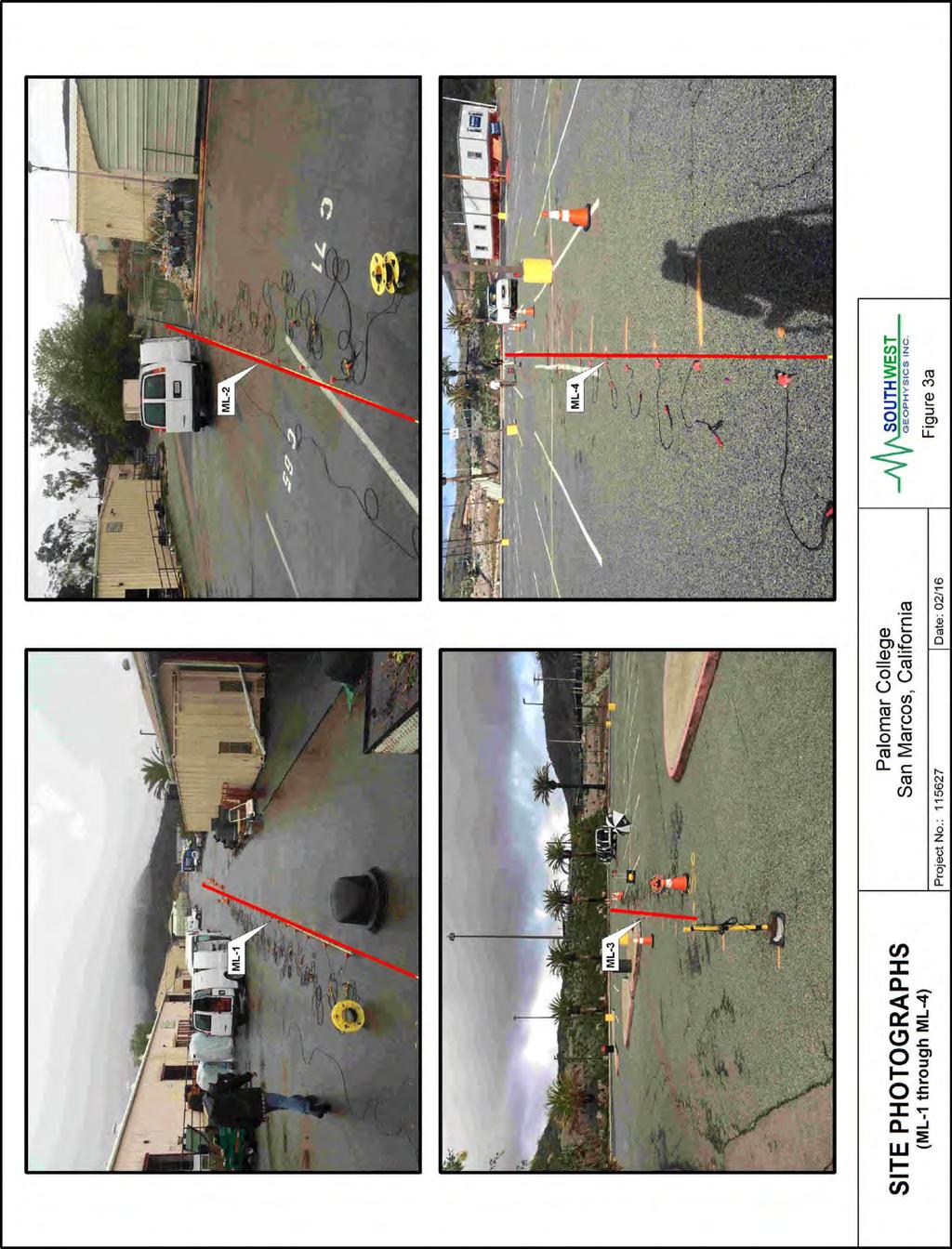
168

169
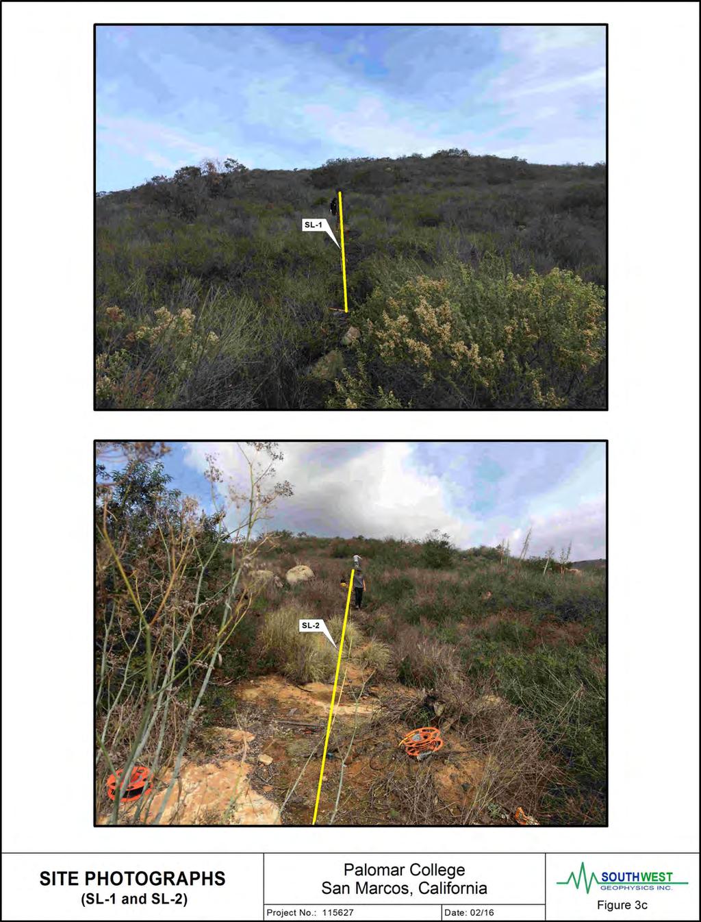
170
171
172
173
174
175
176

177
178
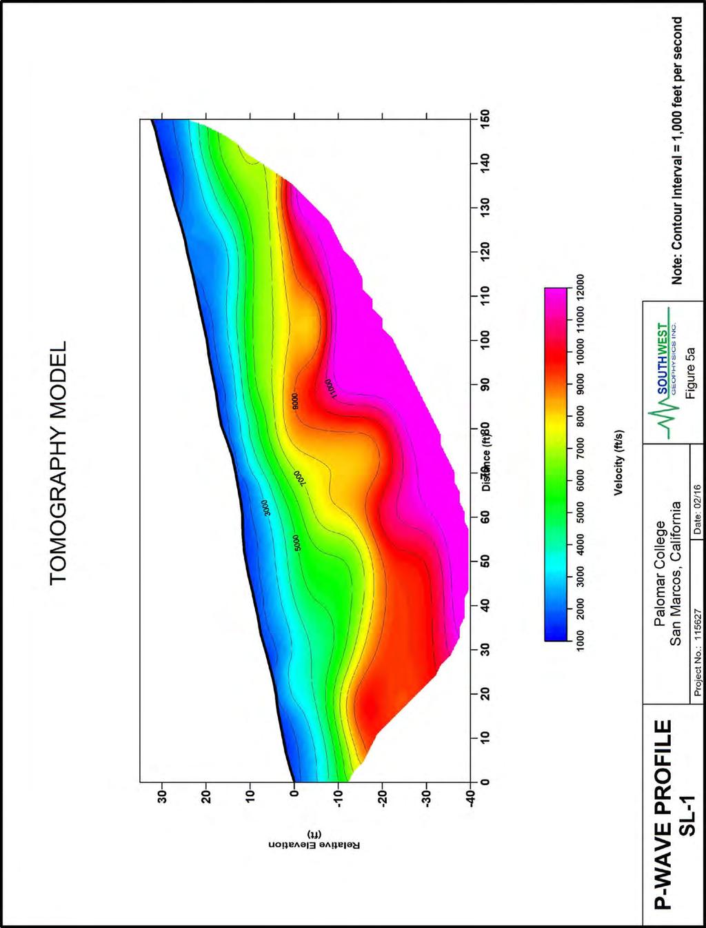
179
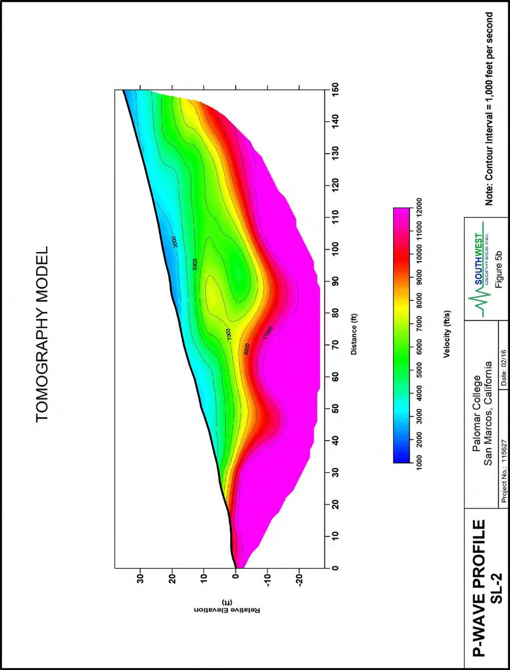
180
IV. ENVIRONMENTAL IMPACT ANALYSIS G. GEOLOGY AND SOILS
 IV. ENVIRONMENTAL IMPACT ANALYSIS G. GEOLOGY AND SOILS The following section is a summary of the geotechnical report conducted for the proposed project. The Report of Geotechnical Investigation Proposed
TCMC Parking Structure and Main Entry 06/12/2018 ADDENDUM #1. The following items are issued as part of this Addendum:
 TCMC Parking Structure and Main Entry 06/12/2018 ADDENDUM #1 The following items are issued as part of this Addendum: 1. The RFI deadline has been changed to June 18, 2018 at 5 P.M. 2. The project bid
Impact : Changes to Existing Topography (Less than Significant)
") 4.2 Land Resources 4.2.1 Alternative A Proposed Action Impact 4.2.1-1: Changes to Existing Topography (Less than Significant) Development of the project site would involve grading and other earthwork as
4.2 Land Resources 4.2.1 Alternative A Proposed Action Impact 4.2.1-1: Changes to Existing Topography (Less than Significant) Development of the project site would involve grading and other earthwork as
Converse Consultants Geotechnical Engineering, Environmental & Groundwater Science, Inspection & Testing Services
 Converse Consultants Geotechnical Engineering, Environmental & Groundwater Science, Inspection & Testing Services Ms. Rebecca Mitchell Mt. San Antonio College Facilities Planning & Management 1100 North
IV. ENVIRONMENTAL IMPACT ANALYSIS E. GEOLOGY AND SOILS
 IV. ENVIRONMENTAL IMPACT ANALYSIS E. GEOLOGY AND SOILS The following section is a summary of the geotechnical report conducted for the Proposed Project. The Geotechnical Engineering Investigation (the
3.0 SUMMARY OF POTENTIAL GEOTECHNICAL IMPACTS AND MITIGATION MEASURES
 3.0 SUMMARY OF POTENTIAL GEOTECHNICAL IMPACTS AND MITIGATION MEASURES This section summarizes the principal geotechnical conditions that occur in the project area. The potential impact that each condition
IV. ENVIRONMENTAL IMPACT ANALYSIS E. GEOLOGY AND SOILS
 IV. ENVIRONMENTAL IMPACT ANALYSIS E. GEOLOGY AND SOILS The following analysis is based on the Geotechnical Investigation Report, Proposed Mid-Rise Multi- Family Residential Development Project Wetherly
IV. ENVIRONMENTAL IMPACT ANALYSIS E. GEOLOGY/SOILS
 IV. ENVIRONMENTAL IMPACT ANALYSIS E. GEOLOGY/SOILS Except where otherwise noted, the following Section is based on the Preliminary Geotechnical Investigation, Proposed Medical Office Buildings and Mixed-Use
GEOLOGY, SOILS, AND SEISMICITY
 4.9 GEOLOGY, SOILS, AND SEISMICITY 4.9.1 Introduction Information about the geological conditions and seismic hazards in the study area was summarized in the FEIR, and was based on the Geotechnical Exploration
Guidelines for Site-Specific Seismic Hazard Reports for Essential and Hazardous Facilities and Major and Special-Occupancy Structures in Oregon
 Guidelines for Site-Specific Seismic Hazard Reports for Essential and Hazardous Facilities and Major and Special-Occupancy Structures in Oregon By the Oregon Board of Geologist Examiners and the Oregon
SLOPE STABILITY EVALUATION AND ACCEPTANCE STANDARDS
 INFORMATION BULLETIN / PUBLIC - BUILDING CODE REFERENCE NO.: LABC 7006.3, 7014.1 Effective: 01-01-2017 DOCUMENT NO.: P/BC 2017-049 Revised: 12-21-2016 Previously Issued As: P/BC 2014-049 SLOPE STABILITY
Geotechnical Engineering Study, Conifer Senior High School Football Field Improvements, Conifer, Colorado
 2390 South Lipan Street Denver, CO 80223 phone: (303) 742-9700 fax: (303) 742-9666 email: kadenver@kumarusa.com www.kumarusa.com Office Locations: Denver (HQ), Colorado Springs, Fort Collins, and Frisco,
GEOLOGY AND SOILS. This chapter summarizes geologic and geotechnical aspects of the site as they relate to the Project.
 9 GEOLOGY AND SOILS INTRODUCTION This chapter summarizes geologic and geotechnical aspects of the site as they relate to the Project. This chapter utilizes information from the following reports prepared
Date: April 2, 2014 Project No.: Prepared For: Mr. Adam Kates CLASSIC COMMUNITIES 1068 E. Meadow Circle Palo Alto, California 94303
 City of Newark - 36120 Ruschin Drive Project Draft Initial Study/Mitigated Negative Declaration Appendix C: Geologic Information FirstCarbon Solutions H:\Client (PN-JN)\4554\45540001\ISMND\45540001 36120
Roy Pyle March 24, 2017 Chief Facilities Planner Contra Costa Community College District 500 North Court Street Martinez, CA 94533
 State of California Natural Resources Agency Edmund G. Brown Jr., Governor Department of Conservation John G. Parrish, Ph.D., State Geologist California Geological Survey 801 K Street MS 12-31 Sacramento,
IV. ENVIRONMENTAL IMPACT ANALYSIS E. GEOLOGY AND SOILS
 IV. ENVIRONMENTAL IMPACT ANALYSIS E. GEOLOGY AND SOILS INTRODUCTION This section evaluates potential impacts related to geology, including seismicity, and soils associated with development of the proposed
CHAPTER GEOLOGICALLY HAZARDOUS AREAS Applicability Regulations.
 CHAPTER 19.07 GEOLOGICALLY HAZARDOUS AREAS 19.07.010 Applicability. Geologically hazardous areas may pose a threat to the health and safety of citizens when incompatible development is sited in areas of
Appendix B. Geotechnical Investigation
 Appendix B Geotechnical Investigation PRELIMINARY GEOTECHNICAL INVESTIGATION PROPOSED REGAL CINEMAS WESTFIELD NORTH COUNTY SHOPPING CENTER ESCONDIDO, CALIFORNIA Prepared for: WESTFIELD, LLC 2049 Century
 R-1 Conveyor Relocation Project Legend 0 500 1000 1500 ft. This map is a user generated static output from an Internet mapping site and is for general reference only. Data layers that appear on this map
Should you have any questions regarding this clarification, please contact the undersigned at or (925)
") October 8, 2015 Revised October 13, 2015 Contra Costa Community College District 500 Court Street Martinez, CA 94553 Attention: Ron Johnson Subject: Clarification of Grading Requirements Diablo Valley
October 8, 2015 Revised October 13, 2015 Contra Costa Community College District 500 Court Street Martinez, CA 94553 Attention: Ron Johnson Subject: Clarification of Grading Requirements Diablo Valley
3.8 Geology/Soils. Environmental Setting. Topography. Geology and Soils
 3.8 Geology/Soils This section examines whether implementation of the 2004 Land Use Mobility Elements, Zoning Code Revisions, and Central District Specific Plan the will expose people or structures to
Sacramento Modesto Roseville Pleasanton September 19, 2013 Marcia Medina GHD Inc. 417 Montgomery Street, Suite 700 San Francisco, CA Subject: GE
 Sacramento Modesto Roseville Pleasanton September 19, 2013 Marcia Medina GHD Inc. 417 Montgomery Street, Suite 700 San Francisco, CA 94104 Subject: GEOTECHNICAL REPORT AMENDMENT Stonybrook Creek Crossings
SLOPE STABILITY EVALUATION AND ACCEPTANCE STANDARDS
 INFORMATION BULLETIN / PUBLIC - BUILDING CODE REFERENCE NO.: LAMC 98.0508 Effective: 1-26-84 DOCUMENT NO. P/BC 2002-049 Revised: 11-1-02 Previously Issued As: RGA #1-84 SLOPE STABILITY EVALUATION AND ACCEPTANCE
CHRISTIAN WHEELER E N G I N E E R I N G
 CHRISTIAN WHEELER E N G I N E E R I N G REPORT OF PRELIMINARY GEOTECHNICAL INVESTIGATION PROPOSED HIGH STREET APARTMENTS A.P.N. S 499-010-02-00 & 499-010-03-00 HIGH STREET, LA MESA, CALIFORNIA PREPARED
Pierce County Department of Planning and Land Services Development Engineering Section
 Page 1 of 7 Pierce County Department of Planning and Land Services Development Engineering Section PROJECT NAME: DATE: APPLICATION NO.: PCDE NO.: LANDSLIDE HAZARD AREA (LHA) GEOLOGICAL ASSESSMENT REPORT
Geotechnical Evaluation
 Geotechnical Evaluation Neighborhood No. 1 Sewer Pump Station Replacement 16106 4S Ranch Parkway San Diego, California Infrastructure Engineering Corporation 14271 Danielson Street San Diego, California
2. Initial Summary of Preliminary Expert Opinion of Converse and Psomas Reports
 UNITED WALNUT TAXPAYERS PRELIMINARY REVIEW OF NEGATIVE GEOTECHNICAL AND GEOLOGICAL ASPECTS OF CONSTRUCTING EARTHFILL PAD FOR A SOLAR FARM ON THE WEST PARCEL - DRAFT 1. Introduction A licensed Engineering
IV. ENVIRONMENTAL IMPACT ANALYSIS E. GEOLOGY/SEISMIC HAZARDS
 IV. ENVIRONMENTAL IMPACT ANALYSIS E. GEOLOGY/SEISMIC HAZARDS 1. ENVIRONMENTAL SETTING The following analysis of geology and seismic hazards for the Middle School Project is based on the Report of Geotechnical
Converse Consultants Geotechnical Engineering, Environmental & Groundwater Science, Inspection & Testing Services
 Converse Consultants Geotechnical Engineering, Environmental & Groundwater Science, Inspection & Testing Services July 27, 2017 Ms. Rebecca Mitchell Mt. San Antonio College Facilities Planning & Management
ENGINEER S CERTIFICATION OF FAULT AREA DEMONSTRATION (40 CFR )
") PLATTE RIVER POWER AUTHORITY RAWHIDE ENERGY STATION BOTTOM ASH TRANSFER (BAT) IMPOUNDMENTS LARIMER COUNTY, CO ENGINEER S CERTIFICATION OF FAULT AREA DEMONSTRATION (40 CFR 257.62) FOR COAL COMBUSTION RESIDUALS
PLATTE RIVER POWER AUTHORITY RAWHIDE ENERGY STATION BOTTOM ASH TRANSFER (BAT) IMPOUNDMENTS LARIMER COUNTY, CO ENGINEER S CERTIFICATION OF FAULT AREA DEMONSTRATION (40 CFR 257.62) FOR COAL COMBUSTION RESIDUALS
J.H. Campbell Generating Facility Pond A - Location Restriction Certification Report
 J.H. Campbell Generating Facility Pond A - Location Restriction Certification Report Pursuant to: 40 CFR 257.60 40 CFR 257.61 40 CFR 257.62 40 CFR 257.63 40 CFR 257.64 Submitted to: Consumers Energy Company
GEOTECHNICAL EVALUATION ESA SECONDARY CONNECTION PROJECT LAKESIDE, CALIFORNIA PDMWD JN
 GEOTECHNICAL EVALUATION ESA SECONDARY CONNECTION PROJECT LAKESIDE, CALIFORNIA PDMWD JN 214007 PREPARED FOR: RBF Consulting 9755 Clairemont Mesa Boulevard, Suite 100 San Diego, California 92124 PREPARED
Setting MOUNTAIN HOUSE NEIGHBORHOODS I AND J INITIAL STUDY 5. ENVIRONMENTAL CHECKLIST 6. GEOLOGY AND SOILS. Issue
 Issue Less Than Significant or No Impact Potential Significant Impact Adequately Addressed in MEIR MEIR Required Additional Review: No Significant Impact Less Than Significant Impact Due to Mitigation
3.1.3 Geology and Soils
 3.1.3 Geology and Soils This section addresses the potential geology and soils impacts associated with implementation of The Villages Escondido Country Club Project (Project). The section describes the
Northern Colorado Geotech
 PRELIMINARY GEOTECHNICAL ENGINEERING REPORT PROPOSED CECIL FARMS DEVELOPMENT WELD COUNTY ROAD 7, BETWEEN ROADS 7 AND 7 SEVERANCE, COLORADO NORTHERN COLORADO GEOTECH PROJECT NO. 0-6 APRIL 0, 06 Prepared
ATTACHMENT A PRELIMINARY GEOTECHNICAL SUMMARY
 ATTACHMENT A PRELIMINARY GEOTECHNICAL SUMMARY Kevin M. Martin, P.E. KMM Geotechnical Consultants, LLC 7 Marshall Road Hampstead, NH 0384 603-489-6 (p)/ 603-489-8 (f)/78-78-4084(m) kevinmartinpe@aol.com
Slope Stability Evaluation Ground Anchor Construction Area White Point Landslide San Pedro District Los Angeles, California.
 Slope Stability Evaluation Ground Anchor Construction Area White Point Landslide San Pedro District Los Angeles, California Submitted To: Mr. Gene Edwards City of Los Angeles Department of Public Works
ENVIRONMENTAL IMPACT ANALYSIS C. GEOLOGY AND SOILS
 IV. ENVIRONMENTAL IMPACT ANALYSIS The following analysis of geology, soils and seismic hazards is based primarily upon the technical report Geotechnical Engineering Investigation Proposed Fashion Square
Mitigation of Liquefaction Potential Using Rammed Aggregate Piers
 ASCE 2011 557 Mitigation of Liquefaction Potential Using Rammed Aggregate Piers R.W. Rudolph, M. ASCE, G.E. 1, B. Serna, M. ASCE, P.E. 2, and T. Farrell, M. ASCE, G.E. 3 1 Principal Consultant, ENGEO,
REPORT OF SUBSURFACE INVESTIGATION AND GEOTECHNICAL EVALUATION POTABLE WATER STORAGE TANK REPLACEMENT EL CAPITAN STATE PARK, CALIFORNIA.
 REPORT OF SUBSURFACE INVESTIGATION AND GEOTECHNICAL EVALUATION POTABLE WATER STORAGE TANK REPLACEMENT EL CAPITAN STATE PARK, CALIFORNIA prepared for Winzler & Kelly Consulting Engineers 4180 Ruffin Road,
4.5 GEOLOGY AND SOILS
 4.5 GEOLOGY AND SOILS This section addresses the project site geology and soils and analyzes potential changes that would result from development of the Wye Specific Plan project. 4.5.1 Environmental Setting
IV. ENVIRONMENTAL IMPACT ANALYSIS G. GEOLOGY AND SOILS
 IV. ENVIRONMENTAL IMPACT ANALYSIS G. GEOLOGY AND SOILS The following section is based upon the City of El Segundo General Plan and General Plan EIR and addresses the following geologic issues: soil erosion,
3.10 GEOLOGY AND SOILS
 3.10 GEOLOGY AND SOILS This section evaluates the potential impacts of the proposed project on geology, soils, and seismic hazards. This evaluation is based on the Preliminary Geotechnical Investigation
B-1 BORE LOCATION PLAN. EXHIBIT Drawn By: 115G BROOKS VETERINARY CLINIC CITY BASE LANDING AND GOLIAD ROAD SAN ANTONIO, TEXAS.
 N B-1 SYMBOLS: Exploratory Boring Location Project Mngr: BORE LOCATION PLAN Project No. GK EXHIBIT Drawn By: 115G1063.02 GK Scale: Checked By: 1045 Central Parkway North, Suite 103 San Antonio, Texas 78232
Geotechnical Investigation Juneau Seawalk - Taku Fisheries to Miner s Wharf Juneau, Alaska DM&A Job No
 Duane Miller & Associates 5821 Arctic Boulevard, Suite A Anchorage, AK 99518-1654 (907) 644-3200 Fax 644-0507 Arctic & Geotechnical Engineering May 4, 2006 Tetra Tech/KCM, Inc. 1971 First Avenue Seattle,
3.12 Geology and Topography Affected Environment
 3 Affected Environment and Environmental Consequences 3.12 Geology and Topography 3.12.1 Affected Environment 3.12.1.1 Earthquakes Sterling Highway MP 45 60 Project Draft SEIS The Kenai Peninsula is predisposed
5.5 Geology and Soils
 5.5 Geology and Soils The analysis in this section of the EIR addresses the potential impacts associated with geology and soils that may occur due to implementation of the proposed Collier Park Renovations
REPORT OF GEOTECHNICAL INVESTIGATION CUYAMACA COLLEGE BUILDING H RENOVATION EL CAJON, CALIFORNIA. Prepared for
 REPORT OF GEOTECHNICAL INVESTIGATION CUYAMACA COLLEGE BUILDING H RENOVATION EL CAJON, CALIFORNIA Prepared for GROSSMONT-CUYAMACA COMMUNITY COLLEGE DISTRICT GAFCON Campus Project Manager 900 Rancho San
REPORT OF PRELIMINARY GEOTECHNICAL EXPLORATION
 REPORT OF PRELIMINARY GEOTECHNICAL EXPLORATION ENKA INTERMEDIATE SCHOOL Sand Hill Road Candler, North Carolina Prepared For: BUNCOMBE COUNTY SCHOOLS Prepared By: AMEC ENVIRONMENT & INFRASTRUCTURE, INC.
Limited Geotechnical Engineering Evaluation Classroom Additions Albany County Campus Laramie, Wyoming
 Limited Geotechnical Engineering Evaluation Classroom Additions Albany County Campus 2300 Missile Drive, Cheyenne, Wyoming 82001 Phone 307-635-0222 www.stratageotech.com Limited Geotechnical Engineering
9. GEOLOGY, SOILS, AND MINERALS
 June 28, 2018 Page 9-1 9. GEOLOGY, SOILS, AND MINERALS This EIR chapter describes the existing geological, soil, and mineral conditions in the planning area. The chapter includes the regulatory framework
GEOTECHNICAL EVALUATION CHAPEL HILLS WATER CAMPUS MALLARD DRIVE AND STATE ROUTE 179 SEDONA, ARIZONA
 GEOTECHNICAL EVALUATION CHAPEL HILLS WATER CAMPUS MALLARD DRIVE AND STATE ROUTE 179 SEDONA, ARIZONA PREPARED FOR: Arizona Water Company 7580 North Dobson Road, Suite 200 Scottsdale, Arizona 85256 PREPARED
Geology, Soils, and Seismicity
 Section 3.8 Geology, Soils, and Seismicity Introduction This section generally evaluates the effects of the alternatives analyzed in this Supplemental DEIS with regard to geology, soils and seismicity.
5.11 Geology and Soils
 5.11 Geology and Soils 5.11 GEOLOGY AND SOILS This section evaluates the geologic and seismic conditions within the City of Azusa and evaluates the potential for geologic hazard impacts associated with
June 9, R. D. Cook, P.Eng. Soils Engineer Special Services Western Region PUBLIC WORKS CANADA WESTERN REGION REPORT ON
 PUBLIC WORKS CANADA WESTERN REGION REPORT ON GEOTECHNICAL INVESTIGATION PROPOSED MARTIN RIVER BRIDGE MILE 306.7 MACKENZIE HIGHWAY Submitted by : R. D. Cook, P.Eng. Soils Engineer Special Services Western
IV. ENVIRONMENTAL IMPACT ANALYSIS E. GEOLOGY/SOILS
 IV. ENVIRONMENTAL IMPACT ANALYSIS E. GEOLOGY/SOILS The following discussion is based upon information contained in the Hollywood Redevelopment Plan Amendment EIR and a letter prepared by Geotechnologies,
Background. Valley fills Sites in the Area. Construction over Mine Spoil Fills
 Construction over Mine Spoil Fills Wayne A. Karem, PhD, PE, PG, D.GE 2014 KSPE Annual Conference Background Strip mining; mountaintop and contour mining Creates huge quantities of mine spoil The mine spoil
SUPPLEMENTARY INVESTIGATION AND LABORATORY TESTING Aggregate Resource Evaluation Proposed Bernand Quarry San Diego County, California
 October 3, 2 Mr. Mark San Agustin Project No. 28-- Home Land Investments Document No. -92 2239 Curlew Street San Diego, CA 92 SUBJECT: SUPPLEMENTARY INVESTIGATION AND LABORATORY TESTING Aggregate Resource
Geotechnical Investigation Report
 Geotechnical Investigation Report El Centro Aquatic Center Adams Avenue to Park Avenue and 4 th Street to 6 th Street El Centro, California Prepared for: Kimley-Horn and Associates, Inc. 401 B Street,
Earth Mechanics, Inc. Geotechnical & Earthquake Engineering
 TECHNICAL MEMORANDUM EMI PROJECT NO: 13-116 DATE: October 29, 2013 PREPARED FOR: Mr. Todd W. Dudley / AECOM PREPARED BY: SUBJECT: (Raja) S. Pirathiviraj and Lino Cheang / (EMI) Preliminary Foundation Report
10. GEOTECHNICAL EXPLORATION PROGRAM
 Geotechnical site investigations should be conducted in multiple phases to obtain data for use during the planning and design of the tunnel system. Geotechnical investigations typically are performed in
CHRISTIAN WHEELER E N G I N E E R I N G
 CHRISTIAN WHEELER E N G I N E E R I N G REPORT OF PRELIMINARY GEOTECHNICAL INVESTIGATION PROPOSED SOLTYS RESIDENCE 56 LA GLORIETA RANCHO SANTA FE, CALIFORNIA PREPARED FOR ROBERT AND MICHELLE SOLTYS 038
ENCE 3610 Soil Mechanics. Site Exploration and Characterisation Field Exploration Methods
 ENCE 3610 Soil Mechanics Site Exploration and Characterisation Field Exploration Methods Geotechnical Involvement in Project Phases Planning Design Alternatives Preparation of Detailed Plans Final Design
COMMUNITY DEVELOPMENT DEPARTMENT POLICY & PROCEDURE
 COMMUNITY DEVELOPMENT DEPARTMENT POLICY & PROCEDURE Policy No: DSP-OO3 Release Date: January 1, 2014 Effective Date: January 1, 2014 Revision Date: March 1, 2018 TITLE: The City Policy for Site Specific
3.18 GEOLOGY AND SOILS
 3.18 GEOLOGY AND SOILS This section discusses geologic resource concerns as they relate to the environment, public safety, and project design both during construction and after completion of the project.
3.4 Geology/Soils/Paleontological Resources
 Section 3.4 Geology, Soils, and Paleontological Resources This section evaluates potential geology and soils impacts, and also paleontological impacts. The analysis is based on a preliminary geotechnical
CCR Surface Impoundment Location Restrictions Demonstration. MidAmerican Energy Company, Louisa Generating Station
 CCR Surface Impoundment Location Restrictions Demonstration MidAmerican Energy Company, Louisa Generating Station Final October 17, 2018 CCR Surface Impoundment Location Restrictions Demonstration Prepared
IV. ENVIRONMENTAL IMPACT ANALYSIS G. GEOLOGY AND SOILS
 IV. ENVIRONMENTAL IMPACT ANALYSIS G. GEOLOGY AND SOILS INTRODUCTION The information and analysis in this section is based primarily on the following report, which is included in Appendix IV.G of this EIR:
14 Geotechnical Hazards
 Volume 2: Assessment of Environmental Effects 296 14 Geotechnical Hazards Overview This Chapter provides an assessment of the underlying geotechnical conditions to identify: any potential liquefaction
Preliminary Geotechnical Engineering Report
 Preliminary Geotechnical Engineering Report Park 3 Barrow County, Georgia July, Terracon Project No. 4906 Prepared For: Winder Barrow Industrial Authority Prepared By: Terracon Consultants, Inc. Atlanta,
GEOLOGIC HAZARDS ASSESSMENT AND GEOTECHNICAL EVALUATION NEW ACADEMIC BUILDING LAS POSITAS COLLEGE LIVERMORE, CALIFORNIA
 GEOLOGIC HAZARDS ASSESSMENT AND GEOTECHNICAL EVALUATION NEW ACADEMIC BUILDING LAS POSITAS COLLEGE LIVERMORE, CALIFORNIA PREPARED FOR: Chabot-Las Positas Community College District 5020 Franklin Drive Pleasanton,
CHRISTIAN WHEELER E N G I N E E R I N G
 CHRISTIAN WHEELER E N G I N E E R I N G REPORT OF GEOTECHNICAL INVESTIGATION PROPOSED FOUNDATION UNDERPINNING SMOKETREE CONDOMINIUMS, BUILDINGS 8 AND 9 6050 HENDERSON DRIVE LA MESA, CALIFORNIA SUBMITTED
SURFACE GEOLOGY AND LIQUEFACTION SUSCEPTIBILITY IN THE INNER RIO GRANDE VALLEY NEAR ALBUQUERQUE, NEW MEXICO
 SURFACE GEOLOGY AND LIQUEFACTION SUSCEPTIBILITY IN THE INNER RIO GRANDE VALLEY NEAR ALBUQUERQUE, NEW MEXICO Keith I. Kelson, Christopher S. Hitchcock, and Carolyn E. Randolph William Lettis & Associates,
Hydrogeological Assessment for Part of Lots 2 and 3, Concession 5, Township of Thurlow, County of Hastings 1.0 INTRODUCTION. 1.
 February 10,2017 25506400 Ontario Ltd. Foxboro, ON Attention: Brad Newbatt Re: Hydrogeological Assessment for Part of Lots 2 and 3, Concession 5, Township of Thurlow, County of Hastings 1.0 INTRODUCTION
IV. ENVIRONMENTAL IMPACT ANALYSIS C. GEOLOGY/SOILS
 IV. ENVIRONMENTAL IMPACT ANALYSIS C. GEOLOGY/SOILS The following section is a summary of the preliminary geotechnical consultation conducted for the Proposed Project. The Report of Geotechnical Engineering
Section 4.6 Geology and Soils Introduction
 4.6 invisible_toc_marker County of Kern Section 4.6 Geology and Soils 4.6.1 Introduction As described in Chapter 2 of this Supplemental EIR (SEIR), an EIR was previously certified for the Alta Oak Creek
4.5 GEOLOGY AND SOILS
 4.5 GEOLOGY AND SOILS This section discusses the Project s potential impacts relating to geologic hazards. This section is partially based on the Geotechnical Engineering Report included in Appendix E.
GEOTECHNICAL STUDY REPORT PROPOSED WATER STORAGE TANK WATER SYSTEM IMPROVEMENT WALNUT GROVE, CALIFORNIA. Prepared for: MWH AMERICAS INC.
 GEOTECHNICAL STUDY REPORT PROPOSED WATER STORAGE TANK WATER SYSTEM IMPROVEMENT WALNUT GROVE, CALIFORNIA Prepared for: MWH AMERICAS INC Prepared by: NOVEMBER 2012 GEOTECHNICAL STUDY REPORT PROPOSED WATER
IAEA SAFETY STANDARDS Geotechnical Aspects of Site Evaluation and Foundations in NPPs, NS-G-3.6
 IAEA SAFETY STANDARDS Geotechnical Aspects of Site Evaluation and Foundations in NPPs, NS-G-3.6 Regional Workshop on Volcanic, Seismic, and Tsunami Hazard Assessment Related to NPP Siting Activities and
GEOTECHNICAL INVESTIGATION REPORT
 GEOTECHNICAL INVESTIGATION REPORT La Sierra Avenue Between Sterling Avenue and El Sobrante Road City of Riverside and Unincorporated Riverside County, California Converse Project No. 14-81-137-01 February
BONSALL UNIFIED SCHOOL DISTRICT
 PRELIMINARY GEOTECHNICAL ENGINEERING AND GEOLOGIC HAZARD REPORT PROPOSED HIGH SCHOOL GIRD ROAD PROPERTY, APN: 124-340-34-00 FALLBROOK AREA, SAN DIEGO COUNTY, CALIFORNIA Prepared for BONSALL UNIFIED SCHOOL
Civil Engineering, Surveying and Environmental Consulting WASP0059.ltr.JLS.Mich Ave Bridge Geotech.docx
 2365 Haggerty Road South * Canton, Michigan 48188 P: 734-397-3100 * F: 734-397-3131 * www.manniksmithgroup.com August 29, 2012 Mr. Richard Kent Washtenaw County Parks and Recreation Commission 2330 Platt
Preliminary Geotechnical Evaluation Gooseberry Point Pedestrian Improvements Whatcom County, Washington SITE AND PROJECT DESCRIPTION
 File No. 12-100 Geotechnical & Earthquake Engineering Consultants Mr. Kevin Brown, P.E. Gray & Osborne, Inc. 3710 168 th Street NE, Suite B210 Arlington, Washington 98223 Subject: Draft Report Preliminary
DATA REPORT GEOTECHNICAL INVESTIGATION GALVESTON CRUISE TERMINAL 2 GALVESTON, TEXAS
 DATA REPORT GEOTECHNICAL INVESTIGATION GALVESTON CRUISE TERMINAL 2 GALVESTON, TEXAS SUBMITTED TO PORT OF GALVESTON 123 ROSENBERG AVENUE, 8TH FLOOR GALVESTON, TEXAS 77553 BY HVJ ASSOCIATES, INC. HOUSTON,
Important Concepts. Earthquake hazards can be categorized as:
 Lecture 1 Page 1 Important Concepts Monday, August 17, 2009 1:05 PM Earthquake Engineering is a branch of Civil Engineering that requires expertise in geology, seismology, civil engineering and risk assessment.
 Photo 1 - Southerly view across 2700 parking lot toward existing building. Multi-residential building borders western side of property in upper right of view. Photo 2 - Southerly view across 2750 parking
Appendix 6A Geologic Information about the Project Area prepared by Ninyo & Moore October 2008
 Appendix 6A Geologic Information about the Project Area prepared by Ninyo & Moore October 2008 Appendix 6A: Geologic Information about the Project Area 6A-1Existing Geologic and Subsurface Conditions
An Introduction to Field Explorations for Foundations
 An Introduction to Field Explorations for Foundations J. Paul Guyer, P.E., R.A. Paul Guyer is a registered mechanical engineer, civil engineer, fire protection engineer and architect with over 35 years
TABLE OF CONTENTS /FLD7R Kleinfelder
 TABLE OF CONTENTS CHAPTER PAGE 1 INTRODUCTION 1 1.1 Proposed Construction 1 1.2 Purpose and Scope of Services 2 1.2.1 Geologic and Seismic Hazards 2 1.2.2 Geotechnical Engineering Exploration 3 2 SITE
Geotechnical Investigation
 2015 Cal Poly Pomona, Portland State University, and others. See full permissions statement at end of document. Civil Engineering Writing Project - Genre Unit 3 Geotechnical Site Investigation Report What
APPENDIX E SOILS TEST REPORTS
 Otsego County, NY Site Work Specifications APPENDIX E SOILS TEST REPORTS Blue Wing Services, Inc. July 1, 2010 Blue Wing Services May 20, 2010 Page 2 the site, was not made available to Empire at this
KDOT Geotechnical Manual Edition. Table of Contents
 KDOT Geotechnical Manual 2007 Edition The KDOT Geotechnical Manual is available two volumes. Both volumes are very large electronic (pdf) files which may take several minutes to download. The table of
December 5, Junction Gateway, LLC 7551 W. Sunset Boulevard #203 Los Angeles, CA Mr. James Frost P: Dear Mr.
 December 5, 2014 Junction Gateway, LLC 7551 W. Sunset Boulevard #203 90046 Attn: Re: Mr. James Frost P: 323.883.1800 Geotechnical Update Letter Sunset & Effie Mixed Use Development 4301 to 4311 Sunset
3.5 Geology and Soils
 3.5 GEOLOGY AND SOILS The following reports have been prepared to analyze the geological impacts of the proposed project and are included in their entirety in Appendices F1 through F7 of this Draft Environmental
NOA ASSESSMENT HARRIS QUARRY MENDOCINO COUNTY, CALIFORNIA TABLE OF CONTENTS
 NOA ASSESSMENT HARRIS QUARRY MENDOCINO COUNTY, CALIFORNIA TABLE OF CONTENTS Introduction... 1 Scope of Services... 1 Project Location and Description... 1 Geologic Setting... 1 Regional Geology... 1 Site
Chapter 7 Mudflow Analysis
 Chapter 7 Mudflow Analysis 7.0 Introduction This chapter provides information on the potential and magnitude of mud floods and mudflows that may develop in Aspen due to rainfall events, snowmelt, or rain
(THIS IS ONLY A SAMPLE REPORT OR APPENDIX OFFERED TO THE USERS OF THE COMPUTER PROGRAM
 C A U T I O N!! (THIS IS ONLY A SAMPLE REPORT OR APPENDIX OFFERED TO THE USERS OF THE COMPUTER PROGRAM EQLique&Settle2. THE AUTHOR IS HEREBY RELEASED OF ANY LIABILITY FOR ANY INCORRECT USE OF THIS SAMPLE
Geotechnical Investigation
 F A M I L Y R E S O U R C E S C E N T E R A N D D I S T R I C T P O L I C E H E A D Q U A R T E R S P R O J E C T I N I T I A L S T U D Y S A N B E R N A R D I N O C I T Y U N I F I E D S C H O O L D I
Landslide FE Stability Analysis
 Landslide FE Stability Analysis L. Kellezi Dept. of Geotechnical Engineering, GEO-Danish Geotechnical Institute, Denmark S. Allkja Altea & Geostudio 2000, Albania P. B. Hansen Dept. of Geotechnical Engineering,
IV. ENVIRONMENTAL IMPACT ANALYSIS E. GEOLOGY AND SOILS
 IV. ENVIRONMENTAL IMPACT ANALYSIS E. GEOLOGY AND SOILS INTRODUCTION This section of the (Draft EIR) evaluates potential geology and soils impacts associated with development of the proposed (proposed Project