TABLE OF CONTENTS /FLD7R Kleinfelder
|
|
|
- Steven Floyd
- 6 years ago
- Views:
Transcription
1
2
3
4 TABLE OF CONTENTS CHAPTER PAGE 1 INTRODUCTION Proposed Construction Purpose and Scope of Services Geologic and Seismic Hazards Geotechnical Engineering Exploration 3 2 SITE CONDITIONS Surface Subsurface Groundwater 5 3 GEOLOGY Regional Geology Local Geology Faulting 7 4 GEOLOGIC HAZARDS ASSESSMENT Surface Fault Rupture Ground Shaking Liquefaction Dynamic Compaction Compressible and Collapsible Soils Landslides and Slope Instability Flooding, Tsunami and Seiche Expansive Soils Conclusions 12 5 CONCLUSIONS AND RECOMMENDATIONS Conclusions Site Preparation Stripping and Grubbing Removals Existing Utilities, Wells, and/or Foundation Scarification and Recompaction Reinforced Soil Slope Temporary excavation General Excavations and Slopes Construction Considerations Engineered Fill Materials Compaction Criteria /FLD7R Kleinfelder iv
5 5.6 Trench Backfill Materials Compaction Criteria Foundation Design Allowable Bearing Pressures Estimated Settlements Lateral Resistance CBC Seismic Design Parameters Soil Corrosivity Interior Concrete Slabs Supported-On-Grade Exterior Flatwork Asphalt Concrete Pavement Site Drainage 30 6 ADDITIONAL SERVICES Project Bid Documents Plan and Specifications Review Construction Observation and Testing Additional Copies of Report 32 7 LIMITATIONS 33 8 REFERENCES 35 PLATES 1 Vicinity Map 2 Site Plan and Boring Location Map 3 Geologic Map 4 Historic Seismicity 5 Typical Cross-Section APPENDIX A B C D Field Investigation Laboratory Testing Seismic Hazard Assessment Application for Authorization to Use 70800/FLD7R Kleinfelder v
6 GEOLOGIC HAZARDS ASSESSMENT AND GEOTECHNICAL ENGINEERING EXPLORATION HIDDENBROOKE ELEMENTARY SCHOOL END OF ALDER CREEK ROAD VALLEJO, CALIFORNIA 1 INTRODUCTION This report presents the results of the geologic hazards assessment and geotechnical engineering exploration conducted for the proposed Hiddenbrooke Elementary School located at the end of Alder Creek Road in Vallejo, California. Our services were authorized by Mr. Mel Jordan, Facilities Planner for Vallejo City Unified School District (VCUSD) on April 21, This report includes our recommendations related to the geotechnical aspects of project design and construction. Conclusions and recommendations presented in this report are based on the subsurface conditions encountered at the locations of our explorations and the provisions and requirements outlined in the ADDITIONAL SERVICES and LIMITATIONS sections of this report. Recommendations presented herein should not be extrapolated to other areas or used for other projects without our prior review. 1.1 PROPOSED CONSTRUCTION Our understanding of the project is based on a review of the available site drawings and discussions with the project architect and civil engineer. The available plans show that the proposed project will involve construction of a new school facility including an administration/library building, multipurpose building, and 18 classrooms in five clusters of one to five classrooms. We assume that the building loads will be light to moderate and that a conventional spread footing and slab-on-grade foundation will be used to support the structures. Based on the grading plans available at the time our report was prepared, however, we understand that significant grading is proposed to develop the site. Cuts of 25 to 50 feet are planned at the eastern boundary of the site at the base of the existing slope. Fill slopes ranging from 14 to 26 feet high are planned along the western boundary of 70800/FLD7R Kleinfelder
7 the school development to create level building pads, a park, and grades for pavement and drainage. Excavations for underground utilities are expected to be on the order of three to eight feet below existing site grade. Additional improvements will include paved parking areas, landscaping, paved and turf play areas, and underground utilities. Further details are not known to us at this time. 1.2 PURPOSE AND SCOPE OF SERVICES Geologic and Seismic Hazards This evaluation is directed toward compliance with the recommended guidelines for geologic/seismic reports defined by the California Geological Survey (CGS) Note 42, Guidelines to Geologic/Seismic Reports, Note 44, Guidelines for Preparing Engineering Geologic Reports, Note 48, Checklist for the Review of Engineering Geology and Seismology Reports for California Public Schools, Hospitals, and Essential Services Buildings, Guidelines for Evaluating and Mitigating Seismic Hazards in California, CGS Special Publication 117, and the requirements of the California Code of Regulations, Title 24, 2001, California Building Code. The scope of our services for the geologic and seismic hazards assessment was outlined in our proposal to VCUSD dated March 17, 2006 (reference File No. 40-YP6-055), and included the following: Researching readily available geologic and seismic reports and maps of the area; Review of stereoscopic pairs of aerial photographs; Performing a probabilistic seismic hazard analysis to develop site-specific seismic design criteria in terms of peak ground accelerations for the Design Basis Earthquake (DBE) and the Upper Bound Earthquake (UBE); A brief reconnaissance of the site by our engineering geologist to observe surface features; Evaluation of geologic conditions including the results of the borings and laboratory testing of soil samples completed during the geotechnical investigation; Evaluation of liquefaction and landslide potential based on our exploratory borings as required by CGS Special Publication 117; and, 70800/FLD7R Kleinfelder
8 Preparation of a written report for the site with conclusions and recommendations as required regarding geologic hazards and suitability of the site for the proposed development including site-specific geologic and seismologic maps Geotechnical Engineering Exploration The scope of our services was outlined in our proposal to the VCUSD and included the following: A review of available subsurface information contained in our files pertinent to the proposed construction and project site. Exploration of the subsurface conditions at various locations within the area of the proposed construction utilizing fifteen drilled borings and twelve backhoe test pits. Limited laboratory testing of representative samples obtained during the field investigation to evaluate relevant engineering parameters of the subsurface soils. Engineering analyses on which to base our recommendations for the design and construction of the geotechnical aspects of the project. Preparation of this report which includes: A description of the proposed project A description of the surface and subsurface site conditions encountered during our field investigation Recommendations related to the geotechnical aspects of: Site preparation and engineered fill Site grading and landslide mitigation Temporary excavations and trench backfill Foundation design and construction California Building Code (CBC) seismic site coefficients for use in structural analysis Lateral earth pressures for low retaining structures Concrete slabs supported-on-grade Asphalt concrete pavement sections Site drainage Appendices, which include summaries of our field investigation and laboratory testing programs /FLD7R Kleinfelder
9 2 SITE CONDITIONS 2.1 SURFACE The proposed school site is located at the southern end of Alder Creek Road in the Hiddenbrooke residential development in Vallejo, California. The site is located in a narrow valley with a moderately steep natural slope along the eastern boundary and Alder Creek along the western boundary. A portion of the project area is presently vacant land that was formerly a walnut orchard. Topography is variable across the site with elevations ranging from 285 feet above mean sea level (MSL) in the creek bottom to approximately 355 feet MSL at the upper portions of the slopes. The ground generally slopes from east to west toward Alder Creek and to the south along the creek bottom. 2.2 SUBSURFACE In general, materials encountered in our borings and test pits consisted of layers of medium to very stiff silty and sandy clays to the maximum depths explored of approximately 56½ feet below existing site grade in the borings and 13 feet in the backhoe test pits. Variably weathered mudstone or claystone was encountered in many of the borings and test pits located near the toe of the slope at depths ranging between 1 and 21 feet below existing ground surface. Layers of silty and/or clayey sand, 2 to 10 feet thick, were encountered at various depths in about one-third of the borings and test pits. These layers were loose to medium dense in relative density and were generally fine to coarse grained. Laboratory testing indicates that the clayey soils are moderately to highly expansive. An Expansion Index test on a sample of near surface clay material collected from Test Pit TP-4 resulted in an Expansion Index of 90 suggesting a high potential expansion. A Plasticity Index test conducted on deeper clay with sand at Boring B-12 resulted in a Plasticity Index of 36, suggesting high plasticity and expansion potential /FLD7R Kleinfelder
10 2.3 GROUNDWATER Free groundwater was not encountered in the borings or test pits during our field investigation. It should be noted that groundwater and soil moisture conditions within the area will vary depending on rainfall, irrigation practices, construction, runoff, or other factors not apparent at the time of our field investigation. Our boring and test pit locations are shown on the Boring Location Plan, Plate 2. A discussion of the field investigation and laboratory testing programs is presented in Appendices A and B, respectively of this report. Detailed descriptions of the subsurface conditions encountered during our field investigation are presented on the Logs of Borings, Plates A-2 through A-17 and the Logs of Test Pits, Plates A-18 through A-33 of Appendix A /FLD7R Kleinfelder
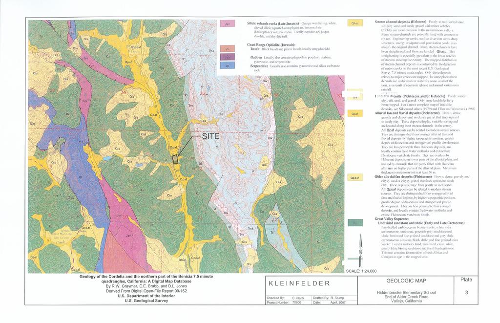
11 3 GEOLOGY 3.1 REGIONAL GEOLOGY The project site is located in the North Coast Range Geomorphic Province of California. The northwest-trending ridges and intervening valleys in the region are controlled by the structure of the Coast Ranges, which consists of northwest-trending folds and faults. The Northern Coast Ranges contain mostly Mesozoic and Cenozoic sedimentary rocks. This region has undergone a complex geologic history of sedimentation, volcanism, folding, faulting, uplifting, and erosion. According to the theory of plate tectonics, these features result from the collision of the Farallon and North American plates and subsequent translational shear along the San Andreas Fault system. Most of the uplift in the Coast Ranges occurred by Middle Miocene time (roughly 16 million years ago), with some uplift continuing through the Quaternary (the last 2 million years). 3.2 LOCAL GEOLOGY The site is located near the central portion of Sky Valley a narrow, northwest-trending valley within Sulphur Spring Mountain that is underlain by Great Valley Sequence (map symbol: Ku) material of early to late Cretaceous age (Graymer, et.al., 1999). The Great Valley Sequence is generally composed of interbedded carbonaceous-biotite wacke, white-mica-carbonaceous sandstone, greenish-gray mudstone and shale, and laminated fine-grained sandstone and gray shale. In the study area the formation was observed to consist mainly of variably weathered mudstones and shales. Structurally, the bedding generally strike northerly with moderate to steep dips towards the east; however, some overturned bedding has been mapped east of the site dipping steeply towards the west. The structure of the immediate area is complex due to thrust faulting, and fault truncated anticlines and synclines. The lower, flatter portions of the site are overlain by alluvial fan and fluvial deposits Pleistocene age (map symbol: Qpaf). These deposits typically consist of brown, stiff to very stiff clays, dense, gravelly and clayey sand or clayey gravel that fines upward to 70800/FLD7R Kleinfelder
12 sandy clay. The deposits display variable sorting and are located along local stream channels. A geologic map showing the site location is shown on Plate FAULTING Vallejo is situated in a region traditionally characterized by few active faults and low to moderate seismic activity. The closest significant fault is the Concord-Green Valley fault is located at about 5.2 km to the east. In addition, the West Napa Fault is located approximately 7.3 km northwest of the site. Locations of the significant active and potentially active faults are shown on Plate 4 along with historical seismicity with earthquake magnitudes 4 or greater during the last 207+ years. A major seismic event on these or other nearby faults may cause substantial ground shaking at the site /FLD7R Kleinfelder
13 4 GEOLOGIC HAZARDS ASSESSMENT A discussion of specific geologic hazards that could impact the site is included below. The hazards considered include: surface fault rupture, seismic shaking, seismically induced ground failures (liquefaction, lateral spreading, dynamic compaction, and landslides), tsunami, seiche, and flooding (seismically induced or otherwise). 4.1 SURFACE FAULT RUPTURE Based on the information provided in Hart and Bryant (1997), the site is not within an Alquist-Priolo Earthquake Fault Zone. Based on our review of the Graymer et. al. geologic map and seismologic reports and maps for the area, no known active, or potentially active faults cross or project toward the site. Additionally, no evidence of active faulting was visible on the site during our site reconnaissance, therefore, it is our opinion that the potential for fault-related surface rupture at the existing school site is low. 4.2 GROUND SHAKING Future ground motions at the site for purposes of structural design and evaluation of liquefaction potential have been analyzed in accordance with the 2001 California Building Code (CBC), CGS Note 48, and Guidelines for Evaluating Seismic Hazards (CGS SP117, 1996). These guidelines and policies consistently require the use of Probabilistic Seismic Hazards Analysis (PSHA) methods to estimate ground motions for the Design Basis Earthquake (DBE, or 10% probability of exceedance in 50 years) and the Upper Bound Earthquake (UBE, or 10% probability of exceedance in 100 years) for public schools (K 12) or hospitals. Our seismic hazard analysis is presented in Appendix C, and concludes that the DBE and the UBE horizontal ground acceleration values are 0.51g and 0.62g, respectively /FLD7R Kleinfelder
14 4.3 LIQUEFACTION Soil liquefaction is a condition where saturated, granular soils undergo a substantial loss of strength and deformation due to pore pressure increase resulting from cyclic stress application induced by earthquakes. In the process, the soil acquires mobility sufficient to permit both horizontal and vertical movements if the soil mass is not confined. Soils most susceptible to liquefaction are saturated, loose, clean (relatively free of clay), relatively young and fine-grained sand deposits. The condition therefore requires the coexistence of susceptible soils, strong ground motions, and shallow groundwater. Within alluvial deposits, sand units conducive to liquefaction may occur as broad layers, confined lens shaped bodies, or elongated sinuous channel deposits. The thickness of such units can vary significantly as well. In areas where strong seismic shaking has occurred, clean and loose gravel deposits have been known to liquefy as well. The primary factors affecting liquefaction potential of a soil deposit are: (1) level and duration of seismic ground motions; (2) soil type and consistency; and (3) depth to groundwater. Soils beneath the site are described on the basis of regional geologic and soils literature along with onsite borings and test pits extending to 55 feet bgs, where weathered bedrock was encountered. Data from the borings and test pits were utilized to assess the liquefaction potential of site soil deposits. The majority of the sand layers were encountered near the ground surface and those at depth do not appear saturated. Information obtained from the borings and test pits at the project site indicate an absence of groundwater beneath the site as presented in the geotechnical report. As such, in our opinion the potential for liquefaction beneath the site is low to nil. The site is adjacent to an existing creek with banks that are approximately 15 feet high. The proposed grading for the site shows that fills on the order of 10 to 15 feet high will be constructed near the top of the creek bank /FLD7R Kleinfelder In our opinion, based on the clayey nature of the natural near-surface soils and the proposed engineered fill, the potential for lateral spreading is low. We have also analyzed the clay and silt layers based on the recent clay criteria by Seed et al (2003). Our analysis shows that the silt and clay layers at depth are not susceptible to liquefaction due to relatively moderate plasticity of the fines. In the absence of liquefaction, there should be no appreciable seismicallyinduced settlement in the soils beneath the site.
15 4.3.1 Dynamic Compaction Another type of seismically-induced ground problem that can occur as a result of seismic shaking is dynamic compaction, or seismic settlement. Such phenomena typically occur in unsaturated, loose granular material or uncompacted fill soils. Since our borings did not encounter these types of soils, dynamic compaction is not anticipated at this site. 4.4 COMPRESSIBLE AND COLLAPSIBLE SOILS Compressible soils are soils that possess low density and are, therefore, incapable of supporting significant vertical loads. Compressible soils tend to coincide with younger, Holocene deposits that have not had sufficient time to densify or become indurated or cemented. Alluvial fan deposits mapped in the region are late Pleistocene-age and have a low potential for being compressible. Collapsible soils are those that have not been subjected to high moisture under current loading conditions and densify when wetted. Mudflows, windblown deposits (i.e. loess), and other hydraulically deposited soils are often susceptible to collapse. Soils within this area were deposited by alluvial conditions and are not expected to be collapsible. 4.5 LANDSLIDES AND SLOPE INSTABILITY Landslides, varying in size from a few tens of feet to several hundreds of feet wide, are present in the general area, as well as on the easterly slopes of the site. The slides on site consist of both recent active slides, as well as older slide deposits. The unstable slide material is within areas underlain by highly fractured Great Valley Sequence material. The thinly bedded shales typically slake, or decompose rapidly, when exposed to water at the surface, thereby resulting in slope instability. The approximate limits of the slides identified on the subject site are shown on Plate 2. Further discussions and recommendations for landslide remedial work is presented in subsequent sections of this report. Indications of soil creep, which is the imperceptibly slow downslope movement due to gravity and cyclic soil shrinkage and swelling of expansive soil, were also noted on the easterly slopes. Such movements lead to higher than typical lateral pressures against 70800/FLD7R Kleinfelder
16 retaining walls and can result in downslope movement of shallow based structures, such as fences and concrete slabs-on-grade. Remedial methods to control soil creep include: the over-excavation and replacement with non-expansive soils; and, the design of new structures to resist the additional lateral soil pressures that will be generated by expansive soils, are discussed within this report. 4.6 FLOODING, TSUNAMI AND SEICHE The Flood Insurance Rate Map, Community Panel Number B, dated August 2, 1982, prepared by the Federal Emergency Management Agency, indicates that the subject site is located within Flood Zone C. This is the zone designation for areas of minimal flooding potential. Tsunamis, or seismic tidal waves, are caused by off shore earthquakes that can trigger large, destructive sea waves. Since the subject site is not located sufficiently close to the coastline, and to the site s topographic elevation, damage from tsunamis is not considered to be a potential seismic hazard. Seiches are caused when earthquake ground motions cause water to oscillate from one side to the other of a closed or partially closed body of water such as a lake, bay or channel. Since no such feature is located at or adjacent to the proposed campus, damage due to seiche development is not considered to be a potential seismic hazard. 4.7 EXPANSIVE SOILS Expansive soils are characterized by their ability to undergo significant volume change (shrink or swell) due to variations in moisture content. Changes in soil moisture content can result from rainfall, landscape irrigation, utility leakage, roof drainage, perched groundwater, drought, or other factors and may cause unacceptable settlement or heave of structures, concrete slabs supported-on-grade, or pavements supported over these materials. Depending on the extent and location below finished subgrade, these soils could have a detrimental effect on the proposed construction. Near-surface soils at the site consist of medium plasticity to high plasticity clay with variable amounts of silt and sand, underlain by silty clay and clayey and silty sands based on the results of our Expansion Index and Plasticity Index tests /FLD7R Kleinfelder With proper
17 preparation as recommended in subsequent sections of this report, these soils are not expected to adversely affect project performance. 4.8 CONCLUSIONS Based on the results of our study, the site should not be adversely affected by any known geologic hazards. 1. The site is not within any current Alquist-Priolo Earthquake Fault Zone. There are no known faults or shear zones extended through the site that would endanger the development due to ground rupture. 2. The potential for adverse impacts due to liquefaction of the alluvial soils at the site is considered low because of the discontinuous nature of the sandy layers encountered in our test borings and the presence of a significant thickness of non-liquefiable soils above the potentially liquefiable layers. 3. The potential for landslides or other downslope earth movements is very low due to the relatively flat topography. 4. The inland location for the site makes damage due to tsunamis or seiches unlikely. 5. The Flood Insurance Rate Map, Community-Panel Number B, dated August 2, 1982, prepared by the Federal Emergency Management Agency, indicates that the site is in Flood Zone C, which is designated for areas of minimal flooding /FLD7R Kleinfelder
18 5 CONCLUSIONS AND RECOMMENDATIONS 5.1 CONCLUSIONS Based upon the results of our exploration, it is our opinion that the site is suitable for the proposed development from a geotechnical engineering standpoint, provided the recommendations presented in this report are incorporated into the final plans and specifications for the subject project. We conclude that there are no known geologic hazards that would preclude the proposed development. It is highly likely that the site will be subject to moderate to strong seismic shaking during the lifetime of the facility. The U.S. Geological Survey (USGS) Working Group on California Earthquake Probabilities determined that there is a 62% chance of at least one magnitude 6.7 or greater earthquake occurring in the San Francisco Bay region prior to 2032 (Working Group, 2003). To minimize the potential for structural distress, the new improvements should be designed and constructed according to the most current earthquake resistance standards for Seismic Zone 4, as outlined in the California Building Code and Uniform Building Code. A key consideration for development of the school site will be mitigation of the landslide conditions on the slope to the east. Based on our evaluations, it appears that the bulk of the landslide material will be removed by the proposed grading. The surficial landslide deposits that will remain at the top of the slope will need to be buttressed. In addition, the bedrock that will be exposed in the cut slope is prone to instability and will require treatment to provide a stable slope face. We understand that there are designated wetlands present on the site in areas that will be developed. Some of these wetlands will be removed by the proposed grading and others will need to be avoided. The grading contractor should review information pertinent to the wetlands and plan their activities for conformance to the wetland mitigation/avoidance plans /FLD7R Kleinfelder
19 Based on our experience in the area, cut slopes in natural materials should be no steeper than three (3) horizontal to one (1) vertical (3(h):1(v)). The current grading plan shows a proposed 2(h):1(v) cut, which is too steep for the materials. We understand that because of site constraints the slope can not be cut flatter. As such, a reinforced slope should be used. Our initial evaluation indicates that a reinforced soil slope cut be constructed at a 1½(h):1(v) inclination. Preliminary recommendations for a reinforced soil slope are presented in subsequent sections of this report. Also of significance to the project is the presence of near surface potentially expansive clay soils. Expansive clays are subject to shrinking and swelling, due to variations in moisture content, resulting in the potential for moderate expansion pressures. Careful compaction control and moisture conditioning will be necessary for the clayey soils. Grading specifications and structural foundation design, to minimize potential damage due to these expansive pressures, are presented. The proposed structures may be supported upon conventional continuous perimeter spread foundations and isolated interior spread foundations sized for low to moderate bearing pressures. Interior slabs-on-grade should be supported on a minimum of 12 inches of non-expansive imported fill. Discussion of these factors, as well as other recommendations for construction of the proposed improvements are presented in the following sections of this report. 5.2 SITE PREPARATION We anticipate that significant cutting and filling will be required during site grading. Site preparation will also include the removal of existing trees and any abandoned underground utility lines. All site preparation activities, including required removals, should extend five feet horizontally beyond the limits of the proposed building pads and adjacent walkways, though we anticipate that the proposed mass grading should encompass the required overbuild. Removal of abandoned underground utility lines should include the removal of any granular trench backfill material associated with the utility line. It is important that during tree removal, the root system be removed also. The following items are recommended for preparation of the site: 70800/FLD7R Kleinfelder
20 5.2.1 Stripping and Grubbing The site should be stripped of all organic materials within cut, fill, structural pad, and pavement areas. It is estimated that this will require the removal of one to three inches of surface soils in some areas. The organic topsoil can be stockpiled and may be used for landscaping purposes; that is, the upper one foot of material used for vegetation in areas not supporting structures or pavements. Strippings with organics should not be incorporated into any structural fill. Deeper stripping and grubbing will be necessary during tree removal to sufficiently clear out the root system. The resulting depressions should be dish shaped to allow compaction equipment to enter, and be backfilled with compacted material meeting the specifications listed below Removals All areas to receive engineered fill or to support project features should be stripped down to native, undisturbed material. After stripping and the removal of underground utility lines, if any areas or pockets of soft or saturated soils are encountered, they should likewise be over-excavated to firm native material and replaced with engineered fill constructed as recommended in this report Existing Utilities, Wells, and/or Foundation Although not encountered during our field investigation, it is possible abandoned utility lines, septic tanks, cesspools, wells, and/or foundations may exist on site. If encountered within the area of construction, these items should be removed and disposed of off-site; and existing wells should be abandoned in accordance with applicable regulatory requirements. Existing utility pipelines that extend beyond the limits of the proposed construction and that are to be abandoned in-place should be sealed with cement grout to prevent migration of soil and/or water. All excavations resulting from removal activities should be cleaned of loose or disturbed material (including all previously-placed backfill) and dish-shaped with sides sloped three horizontal to one vertical, 3(h):1(v) or flatter to permit access for compaction equipment Scarification and Recompaction All clay soils to receive engineered fill, and the structural pad at grade, should be scarified to a minimum depth of twelve inches, moisture conditioned, and recompacted 70800/FLD7R Kleinfelder
21 to between 88 and 92 percent of the maximum dry density, as determined by the ASTM D1557 test method. The moisture content of the scarified soils to be recompacted should be at least three percent above the optimum moisture content at the time of compaction. Moisture conditioning of the clayey soils is important, as this tends to preswell the clays to reduce future expansive pressures. Over-compaction of on-site clays is not desirable, as this will increase the potential for volume changes. In-place scarification and compaction may not be adequate to densify all disturbed soil within areas grubbed or otherwise disturbed below a depth of about 8 inches. Therefore, overexcavation of disturbed soil, scarification and compaction of the exposed subgrade, and replacement with engineered fill may be required to sufficiently densify all disturbed soil. Should site grading be performed during or subsequent to wet weather, near-surface site soils may be significantly above the optimum moisture content. Additionally, it is common to encounter wet, unstable soils upon removal of site pavements or flatwork as a result of subsurface moisture becoming trapped beneath relatively impervious asphalt concrete or portland cement concrete surfaces. Perched groundwater may also develop above dense, cemented on-site soils or rock, saturating near-surface materials. These conditions could hamper equipment maneuverability and efforts to compact site soils to the recommended compaction criteria. Disking to aerate, chemical treatment, replacement with drier material, stabilization with a geotextile fabric or grid, or other methods may be required to reduce excessive soil moisture and facilitate earthwork operations. 5.3 REINFORCED SOIL SLOPE Reinforced soil slopes should be constructed in accordance with the details shown on Plate 5. The initial slope should be cut at 1.5(h):1(v) to allow a 20 feet long grid length. The required benches must be cut during grid placement, not before, to prevent degradation of the supporting material. Geogrid should be placed at a maximum two feet vertical spacing. The geogrid should be wrapped at the face of the slope as shown on. Plate 5. Engineered fill for the reinforced soil slope should be compacted to a minimum of 90 percent relative compaction based on ASTM D1557 test methods /FLD7R Kleinfelder
22 Drains consisting of Miradrain pre-fabricated drainage board should be placed on benches at a maximum five feet vertical spacing and daylight at the slope face. Engineered fill should be placed as described in Section 5.5 below. The finished slope should be covered with an erosion control mat. 5.4 TEMPORARY EXCAVATION General All excavations must comply with applicable local, state, and federal safety regulations including the current OSHA Excavation and Trench Safety Standards. Construction site safety generally is the sole responsibility of the Contractor, who shall also be solely responsible for the means, methods, and sequencing of construction operations. We are providing the information below solely as a service to our client. Under no circumstances should the information provided be interpreted to mean that Kleinfelder is assuming responsibility for construction site safety or the Contractor's activities; such responsibility is not being implied and should not be inferred. It is our professional opinion that utility trench side slopes in undisturbed clayey soils and bedrock will remain near vertical to a depth of five feet or so. It should be recognized that trench wall instability should be anticipated during times of high groundwater levels when soils are saturated or nearly saturated, and also due to moisture loss and equipment vibration. Safety of trench excavation is the responsibility of the contractor. We recommend that excavation construction practices conform to requirements presented by OSHA 29 CFR Part 1926 (Occupation Safety and Health Standards - Excavations; Final Rule) Excavations and Slopes The Contractor should be aware that slope height, slope inclination, or excavation depths (including utility trench excavations) should in no case exceed those specified in local, state, and/or federal safety regulations (e.g., OSHA Health and Safety Standards for Excavations, 29 CFR Part 1926, or successor regulations). Such regulations are strictly enforced and, if they are not followed, the Owner, Contractor, and/or earthwork and utility subcontractors could be liable for substantial penalties /FLD7R Kleinfelder
23 Near-surface soils encountered during our field investigation consisted predominately of silty clay. In our opinion these soils would be considered a Type B soil when applying the OSHA regulations. For this soil type OSHA recommends a maximum slope inclination of 1 horizontal to 1 vertical, 1(h):1(v), or flatter for excavations 20 feet or less in depth. Steeper cut slopes may be utilized for excavations less than five feet deep depending on the strength, moisture content, and homogeneity of the soils as observed in the field. In addition, steeper slopes are permissible in the bedrock, however, they should be monitored by an engineering geologist to document their stability during construction of the reinforced soil slope Construction Considerations Heavy construction equipment, building materials, excavated soil, and vehicular traffic should not be allowed within 1/3 the slope height from the top of any excavation. Support systems such as shoring, bracing, or underpinning may be required to provide structural stability and to protect personnel working within the excavation where stability is a concern. Shoring, bracing, or underpinning required for the project (if any) should be designed by a professional engineer registered in the State of California. During wet weather, earthen berms or other methods should be used to prevent runoff water from entering all excavations. All runoff water should be collected and disposed of outside the construction limits. Import fill material (engineered fill), if required, should be a granular, low to nonexpansive soil meeting the following requirements: 5.5 ENGINEERED FILL Materials All engineered fill soils should be nearly-free of organic or other deleterious debris, essentially non-plastic, and less than three inches in maximum dimension. In general, well-graded mixtures of gravel, sand, non-plastic silt, and small quantities of rock fragments, and/or clay are acceptable for use as engineered fill. All imported fill shall be certified as clean from the source (not from former industrial sites or similar 70800/FLD7R Kleinfelder
24 locations; not chemically affected). Guidance for characterization of imported fill for school sites is presented in the California Department of Toxic Substances Control (DTSC) guidance document entitled Information Advisory - Clean Imported Fill Material dated October 2001 ( Specific requirements for engineered fill, as well as applicable test procedures to verify material suitability, are provided below. TABLE 1: ENGINEERED FILL REQUIREMENTS Fill Requirement Test Procedures Gradation ASTM 1 Caltrans 2 Sieve Size Percent 3 inch 100 D ¾ inch D No D No D No D No D Plasticity Liquid Limit Plasticity Index <30 <12 D Organic Content Less than 3% D Expansion Potential (UBC 18-2) Less than Maximum Dry Density More than 105 pcf D American Society for Testing and Materials Standards (latest edition) 2 State of California, Department of Transportation, Standard Test Methods (latest edition) All import fill should be tested for compliance by our firm prior to delivery to the site. Import fill material should be compacted to a minimum of 90 percent, with a moisture content at or above the optimum level, as determined by the ASTM D1557 test procedures /FLD7R Kleinfelder
25 5.5.2 Compaction Criteria All structural fills should be placed in lifts no greater than eight inches in loose thickness and compacted to a relative compaction between 88 and 92 percent of the maximum dry density, at a uniform moisture content at least three percent above the optimum moisture content at the time of compaction for clayey soils. Granular or non-cohesive soils should be compacted to a minimum of 90 percent relative compaction at a uniform moisture content at or above the optimum moisture content at the time of compaction. Compaction should be increased to at least 95 percent in the upper twelve inches in all areas to support pavement sections subject to vehicular loadings. Compaction specifications recommended above are not the only criteria for proper fill placement. Other than the degree of relative compaction and the percentage of water content, the stability of the fill material is also an important factor to the performance of the fill. A fill can be unsuitable, such as pumping, even if the fill material meets the required compaction specifications. Therefore, a fill should not be considered suitable, regardless of the degree of relative compaction, if the material is unstable. We recommend that final grading plans be reviewed by Kleinfelder for conformance to our design recommendations prior to construction bidding. All site preparation, overexcavation, fill placement and moisture conditioning should be observed and tested by a representative of our firm. 5.6 TRENCH BACKFILL In order to provide suitable support of the concrete slabs, foundations, and asphalt pavements, it is important that utility trenches passing beneath the subgrade be properly backfilled and that the backfill be compacted to an adequate density Materials Pipe zone backfill (i.e., material beneath and in the immediate vicinity of the pipe) should consist of native or imported soil less than one inch in maximum dimension; trench zone backfill (i.e., material placed between the pipe zone backfill and finished subgrade) may consist of native soil which meets the requirements for engineered fill provided above /FLD7R Kleinfelder
26 If any areas of soft subgrade are exposed in the bottom of the trench excavation, it may be necessary to place a geotextile or geogrid such as Mirafi 500X or Tensar BX1100, respectively, or an approved equivalent, in the bottom of the excavation prior to placing pipe bedding material. Materials removed from the trenches should be suitable for use as backfill provided that they do not contain any deleterious materials or rock pieces exceeding three inches in largest dimension. If import material is used for pipe or trench zone backfill, we recommend it consist of fine-grained sand. In general, coarse-grained sand and/or gravel is not recommended and should not be used for pipe or trench zone backfill due to the potential for soil migration into the relatively large void spaces present in this type of material and water seepage along trenches backfilled with coarse-grained sand and/or gravel. If coarsegrained backfill is selected, please contact our office for additional recommendations. Recommendations provided above for pipe zone backfill are minimum requirements only. More stringent material specifications may be required to fulfill local codes and/or bedding requirements for specific types of pipes. We recommend the project Civil Engineer develop these material specifications based on planned pipe types, bedding conditions, and other factors beyond the scope of this study Compaction Criteria All trench backfill should be placed and compacted in accordance with recommendations provided above for engineered fill. Within pavement areas, trench backfill should be compacted to at least 95 percent relative compaction within 12 inches of finished subgrade. Mechanical compaction is required. Ponding or jetting is not allowed /FLD7R Kleinfelder
27 5.7 FOUNDATION DESIGN Allowable Bearing Pressures To reduce future moisture changes in the building slab subgrade, we recommend that continuous perimeter wall footings be used. It is our opinion that the anticipated structural loads may be supported upon continuous perimeter spread foundations and isolated interior spread foundations, bearing upon undisturbed firm native soil or properly constructed engineered fill. Continuous spread foundations should be at least 12 inches wide and based at least 24 inches below lowest adjacent interior or exterior grade; isolated spread foundations should have a minimum width of 24 inches and should also be based at least 24 inches below adjacent grade. Continuous and isolated footings embedded to the above-recommended depth may be designed for an allowable soil bearing pressure not exceeding 3,000 pounds per square foot for dead plus live loads. The above bearing pressures may be increased by one-third for transient loads, including either seismic or wind effects. The base of the foundation excavation, to a minimum depth of 12 inches, should be at least three percent above optimum moisture content immediately prior to the placement of concrete. The weight of foundation concrete extending below grade may be disregarded in sizing computations. To resist expansive pressure, we recommend that continuous foundations contain steel reinforcement, consisting of a minimum of four No. 4 bars, two top and two bottom. The actual foundation design and reinforcement, however, should be provided by the design engineer taking into account the structural loadings. Joints in perimeter footings or holes made for utilities, etc., should be sealed to prevent migration of moisture through the footings. Lean concrete or low permeability clay may be used. Perimeter roof gutters discharging into solid drain pipes should be used, and positive drainage away from exterior walls provided. Care should be taken to avoid the drying of soils exposed in the footing excavations. In the summer, it is important to place concrete as soon as possible to prevent loss of moisture from the foundation excavations. Moisture content of the foundation soils should be tested by a representative of Kleinfelder 24 hours prior to pouring of concrete. If the moisture contents are below that specified, foundation materials should 70800/FLD7R Kleinfelder
28 be moisture conditioned by periodic sprinkling or flooding to achieve the recommended moisture content Estimated Settlements If existing fill is identified and properly replaced with engineered fill, we estimate that the settlement of continuous spread foundations will be in the range of ¾ inch, and the isolated footings supporting column loads on the order of ½ inch to ¾ inch. Differential settlements for foundations proportioned for the bearing value recommended above are expected to be less than half this range. The major portion of the settlement will probably occur relatively rapidly during construction with application of the dead load Lateral Resistance Resistance to lateral forces by spread foundations may be computed using either friction or passive pressure. An ultimate friction factor of 0.3 is considered appropriate between the undersurface of the concrete and the supporting subgrade. An ultimate passive earth pressure equivalent to that exerted by a fluid weighing 300 pounds per cubic foot is recommended. Factors of safety should be applied to either mode of resistance selected for design computations. If friction and passive pressures are combined, the larger value should be reduced by 50 percent for design of building foundations. This reduction factor need not be applied to the lateral resistance design of retaining wall foundations that are not a part of the structure. 5.8 CBC SEISMIC DESIGN PARAMETERS For seismic design the site ground motions will depend on the particular earthquake and the resulting site response characteristics. For this site, the closest fault is the Concord-Green Valley fault at a distance of about 5.2 km, according to the Active Fault Near-Source Zones Map E-15 which is published by the ICBO. Due to potential near fault motion resulting from activity on the Concord Green Valley fault, near-source effects should be considered in the structural design of the proposed facilities. Structures with strength discontinuities, soft stories, plan irregularities, discontinuous shear walls and ductile moment frames are particularly vulnerable to these type of motions and should either be avoided or properly evaluated /FLD7R Kleinfelder
29 For a code based equivalent lateral force design, we recommend using the procedures provided in the 2001 CBC. The Near-Source Factors N a and N v in the code are incorporated into the seismic coefficients C a and C v, which are both used to estimate the total design lateral force or shear at the base of the building or structure. The values of these factors depend on the distance of the structure from the fault and the fault type. Parameters for input to seismic modeling are provided on the basis of information contained in this report as follows: TABLE 2: SEISMIC DESIGN PARAMETERS Seismic Design Parameter Reference Symbol Seismic Source Type 1 CBC Table 16A-U A-C B Near Source Factor 1 CBC Table 16A-S/T N a, N v 1.0, 1.2 Seismic Zone CBC Figure 16A Seismic Factor CBC Table 16A-I Z 0.40 Soil Profile Type CBC Table 16A-J S S D Seismic Response Coefficient Recommended Value CBC /Table 16A-Q/R C a, C v 0.45, Fault Activity Map of California and Adjacent Areas with Locations and Ages of Recent Volcanic Eruptions, California Division of Mines and Geology; Jennings, C.W. (1994). If the structural design requires unusual foundation configurations or imposes loads greater than those assumed in this report, our office should be contacted for possible modification to these recommendations. 5.9 SOIL CORROSIVITY A selected sample of the near-surface soil encountered at the site was submitted for chemical analysis for the purpose of corrosion assessment. The sample was tested in general accordance with California Test Methods 643, 422, and 417 for ph and resistivity, soluble chlorides, and soluble sulfates, respectively. The test results are presented in Table 3, Summary of Corrosion Test Results /FLD7R Kleinfelder
30 Boring No. TABLE 3: SUMMARY OF CORROSION TEST RESULTS (Results pending) Sample Depth (feet) Resistivity (Ohm-Cm) ph Water Soluble Sulfates (ppm) Water Soluble Chlorides (ppm) TP TP According to the 2001 California Building Code, Table 19-A-4, a sulfate concentration below 0.10 percent by weight (1,000 ppm) is negligible. A water-soluble chloride content of less than 500 ppm is generally considered non-corrosive to reinforced concrete. A minimum resistivity tests performed on the soil sample indicated that the soil is considered to be corrosive to buried metal objects. A commonly accepted correlation between soil resistivity and corrosivity towards ferrous metals (NACE Corrosion Basics, 1984) is provided below: Minimum Resistivity, ohm-cm Corrosion Potential 0 to 1,000 - Severely Corrosive 1,000 to 2,000 - Corrosive 2,000 to 10,000 - Moderately Corrosive Over 10,000 - Mildly Corrosive We have provided the above preliminary corrosion tests. These tests are only an indicator of potential soil corrosivity for the samples tested. Other soils found on the site may be more, less, or of a similar corrosive nature. Kleinfelder does not practice corrosion engineering. We recommend that a competent corrosion engineer be retained to evaluate the corrosion potential of the site to proposed improvements, to recommend further testing as required, and to provide specific corrosion mitigation methods appropriate for the project INTERIOR CONCRETE SLABS SUPPORTED-ON-GRADE The near-surface native soils have moderate to high expansion potential and will be subject to cycles of shrinking and swelling with variations in soil moisture content. To 70800/FLD7R Kleinfelder
31 minimize the potentially adverse effects of these soils, we recommend that the soil be prepared as discussed in the Site Preparation section of this report, and that the following recommendations are also followed. The soil subgrade should be prepared as outlined in the Site Preparation section of this report. Slabs-on-grade should be supported on a minimum of 12 inches of nonexpansive engineered fill in addition to the slab support section recommended below. It is emphasized that building floor slabs should not be constructed upon a dry subgrade. In addition, we recommend that interior floor slabs be supported upon a minimum fourinch blanket of free draining crushed rock which will serve as a capillary moisture barrier. Gradation of this material should be such that 100 percent will pass a one-inch sieve with none passing the No. 4 sieve. To reduce possible distress to the floor slab resulting from expansion pressures of subgrade soils responding to variations in moisture content, steel reinforcement should be included. The use of rebar, instead of wire mesh, would reduce the amount of possible distress. A modulus of subgrade reaction (k-value) of 100 psi/in should be used for floor slab design. The final design of slabs and reinforcement is the responsibility of the design engineer. If necessary, more stringent structural considerations should govern floor slab design. Subsurface moisture and moisture vapor naturally migrate upward through the soil and, where the soil is covered by a building or pavement, this subsurface moisture will collect. To reduce the impact of this subsurface moisture and the potential impact of introduced moisture, such as landscape irrigation or plumbing leaks, the current industry standard is to place a vapor retarder on the compacted crushed rock layer (described above). This membrane typically consists of visquene or polyvinyl plastic sheeting at least 10 mil in thickness. It should be noted that although capillary break and vapor barrier systems are currently the industry standard, this system may not be completely effective in preventing floor slab moisture problems. These systems will not "moisture proof" the floor slab nor will it assure floor slab moisture transmission rates will meet floor-covering manufacturer standards. The design and construction of such systems are dependent on the proposed use and design of the proposed building and all elements of building design and function should be considered in the slab-on-grade floor design. Building design 70800/FLD7R Kleinfelder
32 and construction may have a greater role in perceived moisture problems since sealed buildings/rooms or inadequate ventilation may result in excessive moisture in a building and affect indoor air quality. Various factors such as surface grades, adjacent planters, the quality of slab concrete, and the permeability of the on-site soils affect slab moisture control performance. In many cases, perceived floor moisture problems are the result of improper curing of floor slabs and flooring adhesives, not excessive slab moisture transmission. We recommend contacting a flooring consultant experienced in the area of concrete slabon-grade floors for specific recommendations regarding your proposed flooring applications. Special precautions must be taken during the placement and curing of all concrete slabs. Excessive slump (high water-cement ratio) of the concrete and/or improper curing procedures used during either hot or cold weather conditions could lead to excessive shrinkage, cracking, or curling in the slabs. High water-cement ratio and/or improper curing also greatly increase the water vapor permeability of concrete. We recommend that all concrete placement and curing operations be performed in accordance with the American Concrete Institute (ACI) Manual. It is emphasized that we are not concrete slab-on-grade floor moisture proofing experts. We make no guarantee nor provide any assurance that use of the capillary break/vapor retarder system will reduce concrete slab-on-grade floor moisture penetration to any specific rate or level, particularly those required by floor covering manufacturers. The builder and designers should consider all available measures for slab moisture protection EXTERIOR FLATWORK Exterior concrete flatwork should be constructed upon a minimum 4-inch thick layer of Class 2 Aggregate Base Rock. The Aggregate Base should be compacted to between 90 and 95 percent relative compaction as determined by the ASTM D1557 test method. This layer should be constructed upon a moisture-conditioned subgrade as outlined above /FLD7R Kleinfelder
33 Moisture-conditioning will help reduce, but will not eliminate, the potential for swelling of the near-surface soils; cracking and vertical movements of the slabs may still result. Sufficient clearance should be allowed for outward opening doors that swing over the exterior flatwork. If adequate clearance is not present, the door bottom may scrape across the slab and not allow the door to open fully. Exterior concrete flatwork should contain steel reinforcement with bar steel preferred over wire mesh. If wire mesh is used it should be in sheet form, as opposed to rolls. Wire mesh should be placed at the midpoint of the slab. Shrinkage crack control joints should have a minimum depth of 25% of the slab thickness. To minimize differential movements between sections, doweling at all joints is recommended. A modulus of subgrade reaction (k-value) of 100 psi/in should be used for slab on grade design. The final design of slabs and reinforcement is the responsibility of the design engineer. If necessary, more stringent structural considerations should govern slab design ASPHALT CONCRETE PAVEMENT One resistance value (R-value) test was performed on a representative sample of anticipated pavement subgrade materials encountered at the site. A laboratory R-value of 5 was obtained on a composite sample from TP-4, which will be the predominant fill material for the proposed paved areas, and was used in preparing the asphalt pavement section recommendations presented below. For the following asphalt concrete pavement design, the State of California 608 design method for flexible pavements was used. We utilized traffic indices of 3.5, 4.5 and 6 which are considered representative of paved play areas; parking areas for automobiles and light trucks; and aisleways for automobiles, bus and light trucks and weekly trash pick-up, respectively. These traffic indices should be reviewed by the project designer and owner to confirm that they are consistent with the actual design traffic loadings /FLD7R Kleinfelder
34 TABLE 4: RECOMMENDED PAVEMENT SECTION ALTERNATIVES (Design R-Value = 5) Type B Asphalt Concrete Class 2 Aggregate Base (R = 78+) Traffic Index = 3.5 Alternative I Alternative II Traffic Index = 4.5 Alternative I Alternative II Traffic Index = 6 Alternative I Alternative II The above recommendations are considered adequate provided the following conditions are met: a. All trench backfill materials should be properly compacted as previously specified in this report. Mechanical compaction is recommended, as jetting or ponding will probably not obtain satisfactory densification. b. Subgrade soil should be stable and non-pumping at the time the baserock and asphaltic surface is placed. c. An adequate drainage system should be provided to prevent both surface water and subsurface seepage from saturating subgrade soils. This is especially important adjacent to the landscaped areas. Curbs adjacent to landscape areas should extend a minimum of three inches into the subgrade soil below the aggregate sections to reduce moisture migration into the soil subgrade. d. The top 12 inches of subgrade soils beneath the pavement should be compacted to at least 95 percent compaction at moisture content at least three percent above the optimum moisture content /FLD7R Kleinfelder
35 e. The aggregate base material should be compacted to at least 95 percent of the relative compaction and meet the requirements of the State of California Specifications for Class 2 Aggregate Base having a minimum R-value of 78. f. The pavement section recommendations presented assume that periodic maintenance of pavements will be done, including sealing of cracks SITE DRAINAGE Final elevations at the site should be planned so that drainage is directed away from all foundations. Ponding of water or concentrated seepage should not be permitted under the building, adjacent to the foundation system, or under paved areas. Perimeter roof gutters connected to solid drain lines should be used, and positive drainage away from exterior wall provided. Pavement areas should be sloped and drainage gradients maintained to carry all surface water off the site. An adequate pavement drainage system should be provided to prevent both surface water and subsurface seepage from saturating pavement subgrade soils. This is especially important adjacent to the landscaped areas. Curbs adjacent to landscape areas should extend a minimum of three inches into the subgrade soil below the aggregate sections to reduce moisture migration into the soil subgrade /FLD7R Kleinfelder
36 6 ADDITIONAL SERVICES 6.1 PROJECT BID DOCUMENTS It has been our experience contractors bidding on the project often contact us to discuss the geotechnical aspects of the project. Informal contacts between Kleinfelder and an individual contractor could result in incomplete or misinterpreted information being provided to the contractor. Therefore, we recommend a pre-bid meeting be held to answer any questions about the report prior to submittal of bids. If this is not possible, questions or clarifications regarding this report should be directed to the project Owner or his designated representative. After consultation with Kleinfelder, the project Owner (or his representative) should provide clarifications or additional information to all contractors bidding the job. 6.2 PLAN AND SPECIFICATIONS REVIEW Continued coordination between the design engineer and the geotechnical engineer is recommended to assure that the design is compatible with the soil and groundwater conditions determined by this exploration. We recommend our firm conduct a general review of final plans and specifications to evaluate that our earthwork and foundation recommendations have been properly interpreted and implemented during design. In the event we are not retained to perform this recommended review, we will assume no responsibility for misinterpretation of our recommendations. Review of project plans and specifications is not part of our current contract for this project /FLD7R Kleinfelder
37 6.3 CONSTRUCTION OBSERVATION AND TESTING We recommend that all earthwork during construction be monitored by a representative from our office, including: Site preparation, site stripping, over-excavation, grading, and compaction of near-surface soils; Construction of the reinforced soil slope: Placement of all engineered fill and trench backfill; Construction of slab subgrades; and, Evaluation of all foundation excavations. The purpose of these services would be to provide Kleinfelder the opportunity to verify the applicability of the recommendations presented in this report to the soil, bedrock and groundwater conditions encountered during construction, and recommend appropriate changes in design or construction procedures if conditions differ from those described herein. Construction observation and testing are not part of our current contract for this project. 6.4 ADDITIONAL COPIES OF REPORT We have provided the addressee (as listed on the attached cover letter) with three (3) bound copies of this report and three copies to the Project Architect. If additional copies are required, we can provide copies at an additional cost (in accordance with our current fee schedule) after receipt of a written request from our client. Under no circumstances will we provide a copy of the report to other design consultants or contractors without written permission from our client. The above services are not included as part of this contract but can be provided by our firm when requested /FLD7R Kleinfelder
38 7 LIMITATIONS The services provided under this contract as described in this report include professional opinions and judgments based on the data collected. These services have been performed according to generally accepted geotechnical engineering practice that exists in Solano County at the time our report was written. This report is issued with the understanding that the owner/developer choose the risk they wish to bear by the expenditures involved with the construction alternatives and scheduling that is chosen. In addition, the owner/developer should understand that there are risks of earth movement and property damage inherent in land development. We are unable to eliminate all risks; therefore, no express or implied warranty is made. This report may be used only by the client and only for the purposes stated, within a reasonable time from its issuance. Land use, site conditions (both on site and off site) or other factors may change over time, and additional work may be required with the passage of time. Any party other than the client who wishes to use this report shall notify Kleinfelder of such intended use by executing the Application for Authorization to Use which is included in the Appendix. Based on the intended use of the report, Kleinfelder may require that additional work be performed and that an updated report be issued. Non-compliance with any of these requirements by the client or anyone else will release Kleinfelder from any liability resulting from the use of this report by any unauthorized party. The conclusions and recommendations of this report are for the proposed additions to the Hiddenbrooke Elementary School campus located in Vallejo, California, as described in the text of this report. The conclusions and recommendations in this report are invalid if: The anticipated design loads change; The site grading differs from that assumed in preparing this report; The structure locations are changed; The report is used for adjacent or other property; The Additional Services section of this report is not followed; 70800/FLD7R Kleinfelder
39 If changes of grades occur between the issuance of this report and construction; or, Any other change is implemented which materially alters the project from that proposed at the time this report was prepared. The conclusions and recommendations presented in this report are based on information obtained from the following: Fifteen test borings; Fifteen test pits; The observations of our engineering geologist and geotechnical engineer; The results of laboratory tests; Results of our previous site studies in the general area; and, Our experience on similar projects with similar soil and groundwater conditions. The exploratory test borings and pits do not provide a warranty as to the conditions which may exist on the entire site. The extent and nature of subsurface soil, bedrock and groundwater variations may not become evident until construction begins. It is possible that variations in soil and bedrock conditions and depth to groundwater could exist beyond the point of exploration, which may require additional studies, consultation, and possible design revisions. If conditions are encountered in the field during construction, which differ from those described in this report, our firm should be contacted immediately to provide any necessary revisions to these recommendations. It is the addressee s and/or developer s responsibility to see that all parties to the project, including the designer, contractor, subcontractors, etc., are made aware of this report in its entirety including the Additional Services and Limitations sections. Other standards or documents referenced in any given standard cited in this report, or otherwise relied upon by the authors of this report, are only mentioned in the given standard; they are not incorporated into it or included by reference, as that latter term is used relative to contracts or other matters of law /FLD7R Kleinfelder
40 8 REFERENCES Bailey, E.J. ed. 1996, Geology of Northern California, California Division of Mines and Geology, Bulletin No Bates, L.E., 1977, Soil Survey of Solano County, California: Agriculture, Soil Conservation Service. U.S. Department of Bryant, W.A., 1981, Fault Evaluation Report (FER-127), Cordelia Fault, Solano County, California: California Division of Mines and Geology. Bryant W.A., 1991, Supplement No. 2 to FER-127, Cordelia Fault, Solano County, California: California Division of Mines and Geology. Bryant, W.A., 1992, Fault Evaluation Report (FER-232), Southern Green Valley Fault, Solano County, California: California Division of Mines and Geology. California Building Code 2001, California Building Standards Commission. California Division of Mines and Geology, 1983, Alquist-Priolo Special Studies Zone Map for the Cordelia 7.5 Quadrangle. California Division of Mines and Geology, 1993a, Alquist-Priolo Earthquake Fault Zone Map for the Cordelia 7.5 Quadrangle. California Division of Mines and Geology, 1993b, Alquist-Priolo Earthquake Fault Zone Map for the Mt. George 7.5 Quadrangle. California Geological Survey 1997 Guidelines for Evaluation and Mitigation of Seismic Hazards in California, Special Publication 117. California Geological Survey, 2004, Note 48 Checklist for Review of Engineering Geology and Seismology Reports for California Public Schools, Hospitals and Essential Services Buildings, January 1, 2004 edition. Eaton, Jerry, 1986, Tectonic Environment of the 1892 Vacaville/Winters Earthquake, and the Potential for Large Earthquakes Along the Western Edge of the Sacramento Valley, California, U.S. Geological Survey, Open-File Report Federal Emergency Management Agency (FEMA), 1991, Flood Insurance Rate Map, Solano County, California (Unincorporated Areas), Community-Panel Number B, dated August 2, /FLD7R Kleinfelder
41 Frizzell, V.A. and Brown, R.D., 1973, Map Showing Recently Active Breaks Along the Green Valley Fault, Napa and Solano Counties, California, Miscellaneous Field Studies Map MF-743: U.S. Geological Survey, scale of 1 inch equals 4 kilometers. Graymer, R.W., Brabb, E.E., and Jones, D.L., 1999, Geology of the Cordelia and the Northern Part of the Benicia 7.5-Minute Quadrangles, California: Derived for the Digital Map Database Open-File Hart, E.W. and Bryant, W.A. 1997, Fault-Rupture Hazard Zones in California: California Division of Mines and Geology, Special Publication 42, 1999 revised edition and Supplement 3. Harwood, David S., and Helley, Edward J., 1987, Late Cenozoic Tectonism of the Sacramento Valley, California, U.S. Geological Survey Professional Paper Harwood, David S., and Helley, Edward J., 1982, Preliminary Structure Contour Map of the Sacramento Valley, California, Showing Major Late Cenozoic Structural Features and Depth of Bedrock, U.S. Geological Survey, Open-File Report Helley, Edward J., and Harwood, David S., 1985, Geologic Map of the Late Cenozoic Deposits of the Sacramento Valley and Northern Sierran Foothills, California, U.S. Geological Survey, Miscellaneous Field Studies Map MF Jennings, Charles W., 1994, Fault Activity Map of California and Adjacent Areas, California Division of Mines and Geology, Map No. 6, scale 1:750,000. Schwartz, P.D., 1994, New Knowledge of Northern California Earthquake Potential: in proceedings of ATC-35 Seminar on New Developments in Earthquake Ground Motion Estimation and Implications for Engineering Design Practice by Applied Technology Council, Redwood City, California, pp. 4-1 to 4-9. Seed, R.B., Cetin, K.O., Moss, R.E.S., Kammerer, A.M., Wu, J., Pestana, J.M., Riemer, M.F., Sancio, R.B., Bray, H.D., Kayen, R.E., and Faris, A., 2003, Recent Advances in Soil Liquefaction Engineering: A Unified Consistent Framework: University of California, Earthquake Engineering Research Center Report Sims, et. al., 1973, Preliminary Geologic Map, Solano County and Parts of Napa, Contra Costa, Marin, and Yolo Counties, California: U.S. Geological Survey, Misc. Field Studies Map MF-484, scale 1:62, /FLD7R Kleinfelder
42 Stein, R.S., and Eketrom, G., 1992, Seismicity and geometry of a 110-km-long blind thrust fault; part 2, Synthesis of the California earthquake sequence: Journal of Geophysical Research, v. 97, part B, No. 4, p Tokimatsu, K., Seed, H.B., 1987, Evaluation of Settlement in Sands Due to Earthquake Shaking. Journal of the Geotechnical Engineering Division, ACE, Vol. 113, No. 8, August, pp Toppozada, T.R., and others, 1981, Preparation of Isoseismal Maps and Summaries of Reported Effects for pre-1900 California Earthquakes: California Division of Mines and Geology Open File Report SAC. United States Geological Survey, USGS 1951 (photorevised 1980), Topographic Map of the Cordelia 7½-Minute Quadrangle, scale 1:24,000. Unruh, J.R., and Moores, E.M., 1992, Quaternary blind thrusting in the southwestern Sacramento Valley, California: Tectonics, v. 11, p Wakabayashi, John, and Smith, David L., 1994, Evaluation of recurrence intervals, characteristic earthquakes, and slip rates associated with thrusting along the Coast Range-Central Valley Geomorphic Boundary, California: Seismological Society of America, v. 84., No. 6, p Wesnousky, S.G., 1986, Earthquakes, Quaternary faults, and seismic hazard in California: Journal of Geophysical Research, v. 91, No. B-12, pages 12,587-12,631. Wong, Ivan G., et al., 1988 Contemporary Seismicity and Tectonics of the Northern and Central Coast Ranges-Sierran Block Boundary Zone, California, Journal of Geophysical Research, Vol. 93, No. B7, pages Working Group on California Earthquake Probabilities, 2003, Earthquake Probabilities in the San Francisco Bay Region: 2003 to 2030 Summary of Findings: U.S. Geological Survey, Fact Sheet Youd, T.L., Idriss, I.M., and 19 others, 2001, Liquefaction Resistance of Soils: Summary Report From the 1996 NCEER and 1998 NCEER//NSF Workshops on Evaluation of Liquefaction Resistance of Soils: ASCE Geotechnical and Geoenvironmental Journal, v. 127, n. 10, p /FLD7R Kleinfelder


43 TO I-80 SITE VICINITY NOT TO SCALE K L E I N F E L D E R DATE: 5/30/2007 DRAFTED BY: S CALLAHAN PROJ. NO FILENAME: a Copyright Kleinfelder, 2007 HIDDENBROOKE ELEMENTARY SCHOOL END OF ALDER CREEK ROAD VALLEJO, CALIFORNIA PLATE NO. 1
44
45
GEOLOGY AND SOILS. This chapter summarizes geologic and geotechnical aspects of the site as they relate to the Project.
 9 GEOLOGY AND SOILS INTRODUCTION This chapter summarizes geologic and geotechnical aspects of the site as they relate to the Project. This chapter utilizes information from the following reports prepared
IV. ENVIRONMENTAL IMPACT ANALYSIS G. GEOLOGY AND SOILS
 IV. ENVIRONMENTAL IMPACT ANALYSIS G. GEOLOGY AND SOILS The following section is a summary of the geotechnical report conducted for the proposed project. The Report of Geotechnical Investigation Proposed
Impact : Changes to Existing Topography (Less than Significant)
") 4.2 Land Resources 4.2.1 Alternative A Proposed Action Impact 4.2.1-1: Changes to Existing Topography (Less than Significant) Development of the project site would involve grading and other earthwork as
4.2 Land Resources 4.2.1 Alternative A Proposed Action Impact 4.2.1-1: Changes to Existing Topography (Less than Significant) Development of the project site would involve grading and other earthwork as
3.0 SUMMARY OF POTENTIAL GEOTECHNICAL IMPACTS AND MITIGATION MEASURES
 3.0 SUMMARY OF POTENTIAL GEOTECHNICAL IMPACTS AND MITIGATION MEASURES This section summarizes the principal geotechnical conditions that occur in the project area. The potential impact that each condition
Converse Consultants Geotechnical Engineering, Environmental & Groundwater Science, Inspection & Testing Services
 Converse Consultants Geotechnical Engineering, Environmental & Groundwater Science, Inspection & Testing Services Ms. Rebecca Mitchell Mt. San Antonio College Facilities Planning & Management 1100 North
IV. ENVIRONMENTAL IMPACT ANALYSIS E. GEOLOGY AND SOILS
 IV. ENVIRONMENTAL IMPACT ANALYSIS E. GEOLOGY AND SOILS The following analysis is based on the Geotechnical Investigation Report, Proposed Mid-Rise Multi- Family Residential Development Project Wetherly
Guidelines for Site-Specific Seismic Hazard Reports for Essential and Hazardous Facilities and Major and Special-Occupancy Structures in Oregon
 Guidelines for Site-Specific Seismic Hazard Reports for Essential and Hazardous Facilities and Major and Special-Occupancy Structures in Oregon By the Oregon Board of Geologist Examiners and the Oregon
IV. ENVIRONMENTAL IMPACT ANALYSIS E. GEOLOGY/SOILS
 IV. ENVIRONMENTAL IMPACT ANALYSIS E. GEOLOGY/SOILS Except where otherwise noted, the following Section is based on the Preliminary Geotechnical Investigation, Proposed Medical Office Buildings and Mixed-Use
SLOPE STABILITY EVALUATION AND ACCEPTANCE STANDARDS
 INFORMATION BULLETIN / PUBLIC - BUILDING CODE REFERENCE NO.: LABC 7006.3, 7014.1 Effective: 01-01-2017 DOCUMENT NO.: P/BC 2017-049 Revised: 12-21-2016 Previously Issued As: P/BC 2014-049 SLOPE STABILITY
IV. ENVIRONMENTAL IMPACT ANALYSIS E. GEOLOGY AND SOILS
 IV. ENVIRONMENTAL IMPACT ANALYSIS E. GEOLOGY AND SOILS The following section is a summary of the geotechnical report conducted for the Proposed Project. The Geotechnical Engineering Investigation (the
Converse Consultants Geotechnical Engineering, Environmental & Groundwater Science, Inspection & Testing Services
 Converse Consultants Geotechnical Engineering, Environmental & Groundwater Science, Inspection & Testing Services July 27, 2017 Ms. Rebecca Mitchell Mt. San Antonio College Facilities Planning & Management
Setting MOUNTAIN HOUSE NEIGHBORHOODS I AND J INITIAL STUDY 5. ENVIRONMENTAL CHECKLIST 6. GEOLOGY AND SOILS. Issue
 Issue Less Than Significant or No Impact Potential Significant Impact Adequately Addressed in MEIR MEIR Required Additional Review: No Significant Impact Less Than Significant Impact Due to Mitigation
SLOPE STABILITY EVALUATION AND ACCEPTANCE STANDARDS
 INFORMATION BULLETIN / PUBLIC - BUILDING CODE REFERENCE NO.: LAMC 98.0508 Effective: 1-26-84 DOCUMENT NO. P/BC 2002-049 Revised: 11-1-02 Previously Issued As: RGA #1-84 SLOPE STABILITY EVALUATION AND ACCEPTANCE
9. GEOLOGY, SOILS, AND MINERALS
 June 28, 2018 Page 9-1 9. GEOLOGY, SOILS, AND MINERALS This EIR chapter describes the existing geological, soil, and mineral conditions in the planning area. The chapter includes the regulatory framework
IV. ENVIRONMENTAL IMPACT ANALYSIS E. GEOLOGY AND SOILS
 IV. ENVIRONMENTAL IMPACT ANALYSIS E. GEOLOGY AND SOILS INTRODUCTION This section evaluates potential impacts related to geology, including seismicity, and soils associated with development of the proposed
5.11 Geology and Soils
 5.11 Geology and Soils 5.11 GEOLOGY AND SOILS This section evaluates the geologic and seismic conditions within the City of Azusa and evaluates the potential for geologic hazard impacts associated with
Mass Wasting. Revisit: Erosion, Transportation, and Deposition
 Mass Wasting Revisit: Erosion, Transportation, and Deposition While landslides are a normal part of erosion and surface processes, they can be very destructive to life and property! - Mass wasting: downslope
4.5 GEOLOGY AND SOILS
 4.5 GEOLOGY AND SOILS This section addresses the project site geology and soils and analyzes potential changes that would result from development of the Wye Specific Plan project. 4.5.1 Environmental Setting
GEOLOGY, SOILS, AND SEISMICITY
 4.9 GEOLOGY, SOILS, AND SEISMICITY 4.9.1 Introduction Information about the geological conditions and seismic hazards in the study area was summarized in the FEIR, and was based on the Geotechnical Exploration
CHAPTER GEOLOGICALLY HAZARDOUS AREAS Applicability Regulations.
 CHAPTER 19.07 GEOLOGICALLY HAZARDOUS AREAS 19.07.010 Applicability. Geologically hazardous areas may pose a threat to the health and safety of citizens when incompatible development is sited in areas of
IV. ENVIRONMENTAL IMPACT ANALYSIS E. GEOLOGY/SOILS
 IV. ENVIRONMENTAL IMPACT ANALYSIS E. GEOLOGY/SOILS The following discussion is based upon information contained in the Hollywood Redevelopment Plan Amendment EIR and a letter prepared by Geotechnologies,
3.8 Geology/Soils. Environmental Setting. Topography. Geology and Soils
 3.8 Geology/Soils This section examines whether implementation of the 2004 Land Use Mobility Elements, Zoning Code Revisions, and Central District Specific Plan the will expose people or structures to
Date: April 2, 2014 Project No.: Prepared For: Mr. Adam Kates CLASSIC COMMUNITIES 1068 E. Meadow Circle Palo Alto, California 94303
 City of Newark - 36120 Ruschin Drive Project Draft Initial Study/Mitigated Negative Declaration Appendix C: Geologic Information FirstCarbon Solutions H:\Client (PN-JN)\4554\45540001\ISMND\45540001 36120
Background. Valley fills Sites in the Area. Construction over Mine Spoil Fills
 Construction over Mine Spoil Fills Wayne A. Karem, PhD, PE, PG, D.GE 2014 KSPE Annual Conference Background Strip mining; mountaintop and contour mining Creates huge quantities of mine spoil The mine spoil
ENVIRONMENTAL IMPACT ANALYSIS C. GEOLOGY AND SOILS
 IV. ENVIRONMENTAL IMPACT ANALYSIS The following analysis of geology, soils and seismic hazards is based primarily upon the technical report Geotechnical Engineering Investigation Proposed Fashion Square
Geotechnical Engineering Study, Conifer Senior High School Football Field Improvements, Conifer, Colorado
 2390 South Lipan Street Denver, CO 80223 phone: (303) 742-9700 fax: (303) 742-9666 email: kadenver@kumarusa.com www.kumarusa.com Office Locations: Denver (HQ), Colorado Springs, Fort Collins, and Frisco,
J. Paul Guyer, P.E., R.A.
 J. Paul Guyer, P.E., R.A. Paul Guyer is a registered mechanical engineer, civil engineer, fire protection engineer and architect with over 35 years experience in the design of buildings and related infrastructure.
Roy Pyle March 24, 2017 Chief Facilities Planner Contra Costa Community College District 500 North Court Street Martinez, CA 94533
 State of California Natural Resources Agency Edmund G. Brown Jr., Governor Department of Conservation John G. Parrish, Ph.D., State Geologist California Geological Survey 801 K Street MS 12-31 Sacramento,
Pierce County Department of Planning and Land Services Development Engineering Section
 Page 1 of 7 Pierce County Department of Planning and Land Services Development Engineering Section PROJECT NAME: DATE: APPLICATION NO.: PCDE NO.: LANDSLIDE HAZARD AREA (LHA) GEOLOGICAL ASSESSMENT REPORT
ENGINEER S CERTIFICATION OF FAULT AREA DEMONSTRATION (40 CFR )
") PLATTE RIVER POWER AUTHORITY RAWHIDE ENERGY STATION BOTTOM ASH TRANSFER (BAT) IMPOUNDMENTS LARIMER COUNTY, CO ENGINEER S CERTIFICATION OF FAULT AREA DEMONSTRATION (40 CFR 257.62) FOR COAL COMBUSTION RESIDUALS
PLATTE RIVER POWER AUTHORITY RAWHIDE ENERGY STATION BOTTOM ASH TRANSFER (BAT) IMPOUNDMENTS LARIMER COUNTY, CO ENGINEER S CERTIFICATION OF FAULT AREA DEMONSTRATION (40 CFR 257.62) FOR COAL COMBUSTION RESIDUALS
 R-1 Conveyor Relocation Project Legend 0 500 1000 1500 ft. This map is a user generated static output from an Internet mapping site and is for general reference only. Data layers that appear on this map
IAEA SAFETY STANDARDS Geotechnical Aspects of Site Evaluation and Foundations in NPPs, NS-G-3.6
 IAEA SAFETY STANDARDS Geotechnical Aspects of Site Evaluation and Foundations in NPPs, NS-G-3.6 Regional Workshop on Volcanic, Seismic, and Tsunami Hazard Assessment Related to NPP Siting Activities and
Slope Stability Evaluation Ground Anchor Construction Area White Point Landslide San Pedro District Los Angeles, California.
 Slope Stability Evaluation Ground Anchor Construction Area White Point Landslide San Pedro District Los Angeles, California Submitted To: Mr. Gene Edwards City of Los Angeles Department of Public Works
Materials. Use materials meeting the following.
 208.01 Section 208. SOIL EROSION AND SEDIMENTATION CONTROL 208.01 Description. Install and maintain erosion and sedimentation controls to minimize soil erosion and to control sedimentation from affecting
4.5 GEOLOGY AND SOILS
 4.5 GEOLOGY AND SOILS This section discusses the Project s potential impacts relating to geologic hazards. This section is partially based on the Geotechnical Engineering Report included in Appendix E.
4.5 GEOLOGY AND SOILS
 4.5.1 Setting 4.5 GEOLOGY AND SOILS a. Regional Geology. The is located in the south central Santa Cruz Mountains in the heart of the Central Coast ranges of California. This is a seismically active region
3.18 GEOLOGY AND SOILS
 3.18 GEOLOGY AND SOILS This section discusses geologic resource concerns as they relate to the environment, public safety, and project design both during construction and after completion of the project.
Appendix C - Geotechnical Report. Landmark Consultants, Inc.
 Appendix C - Geotechnical Report Landmark Consultants, Inc. LCI Report No. LP18128 Fault Map Regional Review of the current Alquist-Priolo Earthquake Fault Zone maps (CGS, 2000a) indicates that
An Introduction to Field Explorations for Foundations
 An Introduction to Field Explorations for Foundations J. Paul Guyer, P.E., R.A. Paul Guyer is a registered mechanical engineer, civil engineer, fire protection engineer and architect with over 35 years
Geology, Soils, and Seismicity
 Section 3.8 Geology, Soils, and Seismicity Introduction This section generally evaluates the effects of the alternatives analyzed in this Supplemental DEIS with regard to geology, soils and seismicity.
IV. ENVIRONMENTAL IMPACT ANALYSIS G. GEOLOGY AND SOILS
 IV. ENVIRONMENTAL IMPACT ANALYSIS G. GEOLOGY AND SOILS The following section is based upon the City of El Segundo General Plan and General Plan EIR and addresses the following geologic issues: soil erosion,
Important Concepts. Earthquake hazards can be categorized as:
 Lecture 1 Page 1 Important Concepts Monday, August 17, 2009 1:05 PM Earthquake Engineering is a branch of Civil Engineering that requires expertise in geology, seismology, civil engineering and risk assessment.
 Rock Slope Analysis Small and Large Scale Failures Mode of Failure Marklands Test To establish the possibility of wedge failure. Plane failure is a special case of wedge failure. Sliding along
REPORT OF SUBSURFACE INVESTIGATION AND GEOTECHNICAL EVALUATION POTABLE WATER STORAGE TANK REPLACEMENT EL CAPITAN STATE PARK, CALIFORNIA.
 REPORT OF SUBSURFACE INVESTIGATION AND GEOTECHNICAL EVALUATION POTABLE WATER STORAGE TANK REPLACEMENT EL CAPITAN STATE PARK, CALIFORNIA prepared for Winzler & Kelly Consulting Engineers 4180 Ruffin Road,
4.9 GEOLOGY AND SOILS
 4.9 GEOLOGY AND SOILS 4.9.1 EXISTING CONDITIONS TOPOGRAPHY AND RELIEF Zone 40 is located in the central portion of Sacramento County. The topography of the county is represented by three physiographic
Preliminary Geotechnical Evaluation Gooseberry Point Pedestrian Improvements Whatcom County, Washington SITE AND PROJECT DESCRIPTION
 File No. 12-100 Geotechnical & Earthquake Engineering Consultants Mr. Kevin Brown, P.E. Gray & Osborne, Inc. 3710 168 th Street NE, Suite B210 Arlington, Washington 98223 Subject: Draft Report Preliminary
4.5 GEOLOGY AND SOILS
 4.5 GEOLOGY AND SOILS This section discusses the proposed project s potential impacts relating to geologic hazards. This section is partially based on the Preliminary Soil Engineering and Geologic Hazards
GEOTECHNICAL STUDY REPORT PROPOSED WATER STORAGE TANK WATER SYSTEM IMPROVEMENT WALNUT GROVE, CALIFORNIA. Prepared for: MWH AMERICAS INC.
 GEOTECHNICAL STUDY REPORT PROPOSED WATER STORAGE TANK WATER SYSTEM IMPROVEMENT WALNUT GROVE, CALIFORNIA Prepared for: MWH AMERICAS INC Prepared by: NOVEMBER 2012 GEOTECHNICAL STUDY REPORT PROPOSED WATER
3E. Geology and Soils
 INTRODUCTION The purpose of this chapter is to evaluate the proposed project s impacts on local geological features and whether it would expose people or structures to adverse geological impacts. Potential
2. Initial Summary of Preliminary Expert Opinion of Converse and Psomas Reports
 UNITED WALNUT TAXPAYERS PRELIMINARY REVIEW OF NEGATIVE GEOTECHNICAL AND GEOLOGICAL ASPECTS OF CONSTRUCTING EARTHFILL PAD FOR A SOLAR FARM ON THE WEST PARCEL - DRAFT 1. Introduction A licensed Engineering
IV. ENVIRONMENTAL IMPACT ANALYSIS E. GEOLOGY/SEISMIC HAZARDS
 IV. ENVIRONMENTAL IMPACT ANALYSIS E. GEOLOGY/SEISMIC HAZARDS 1. ENVIRONMENTAL SETTING The following analysis of geology and seismic hazards for the Middle School Project is based on the Report of Geotechnical
Section 4.6 Geology and Soils Introduction
 4.6 invisible_toc_marker County of Kern Section 4.6 Geology and Soils 4.6.1 Introduction As described in Chapter 2 of this Supplemental EIR (SEIR), an EIR was previously certified for the Alta Oak Creek
Geotechnical Evaluation
 Geotechnical Evaluation Neighborhood No. 1 Sewer Pump Station Replacement 16106 4S Ranch Parkway San Diego, California Infrastructure Engineering Corporation 14271 Danielson Street San Diego, California
ATTACHMENT A PRELIMINARY GEOTECHNICAL SUMMARY
 ATTACHMENT A PRELIMINARY GEOTECHNICAL SUMMARY Kevin M. Martin, P.E. KMM Geotechnical Consultants, LLC 7 Marshall Road Hampstead, NH 0384 603-489-6 (p)/ 603-489-8 (f)/78-78-4084(m) kevinmartinpe@aol.com
14 Geotechnical Hazards
 Volume 2: Assessment of Environmental Effects 296 14 Geotechnical Hazards Overview This Chapter provides an assessment of the underlying geotechnical conditions to identify: any potential liquefaction
4.6 GEOLOGY AND SOILS
 4.6 GEOLOGY AND SOILS The purpose of the Geology and Soils section is to evaluate whether the proposed project would expose people or structures to major geotechnical hazards or substantially contribute
Northern Colorado Geotech
 PRELIMINARY GEOTECHNICAL ENGINEERING REPORT PROPOSED CECIL FARMS DEVELOPMENT WELD COUNTY ROAD 7, BETWEEN ROADS 7 AND 7 SEVERANCE, COLORADO NORTHERN COLORADO GEOTECH PROJECT NO. 0-6 APRIL 0, 06 Prepared
4.6 GEOLOGY AND SOILS
 LSA ASSOCIATES, INC. MARCH 2008 FINAL ENVIRONMENTAL IMPACT REPORT YUCCA VALLEY RETAIL SPECIFIC PLAN The purpose of the Geology and Soils section is to evaluate whether the proposed project would create
Construction Exits Rock pads
 Construction Exits Rock pads SEDIMENT CONTROL TECHNIQUE Type 1 System Sheet Flow Sandy Soils Type 2 System Concentrated Flow [1] Clayey Soils Type 3 System Supplementary Trap Dispersive Soils [1] Minor
Mass Wasting. Requirements for Mass Wasting. Slope Stability. Geol 104: mass wasting
 Mass Wasting Movement of earth materials downslope, driven by Gravitational Forces. Landslides - general term for rock or soil movement. In U.S., on average, mass wasting causes 1 to 2 billion dollars
IV. ENVIRONMENTAL IMPACT ANALYSIS C. GEOLOGY/SOILS
 IV. ENVIRONMENTAL IMPACT ANALYSIS C. GEOLOGY/SOILS The following section is a summary of the preliminary geotechnical consultation conducted for the Proposed Project. The Report of Geotechnical Engineering
CCR Surface Impoundment Location Restrictions Demonstration. MidAmerican Energy Company, Louisa Generating Station
 CCR Surface Impoundment Location Restrictions Demonstration MidAmerican Energy Company, Louisa Generating Station Final October 17, 2018 CCR Surface Impoundment Location Restrictions Demonstration Prepared
IV. ENVIRONMENTAL IMPACT ANALYSIS G. GEOLOGY AND SOILS
 IV. ENVIRONMENTAL IMPACT ANALYSIS G. GEOLOGY AND SOILS INTRODUCTION The information and analysis in this section is based primarily on the following report, which is included in Appendix IV.G of this EIR:
3.10 GEOLOGY AND SOILS
 3.10 GEOLOGY AND SOILS This section evaluates the potential impacts of the proposed project on geology, soils, and seismic hazards. This evaluation is based on the Preliminary Geotechnical Investigation
3.0 SUMMARY OF FINDINGS
 AECOM 500 W Jefferson St. Suite 1600 Louisville, KY 40202 www.aecom.com 502-569-2301 tel 502-569-2304 fax October 17, 2018 Big Rivers Electric Corporation Sebree Generating Station 9000 Highway 2096 Robards,
5.9 Geology and Soils
 5.9 Geology and Soils 5.9 GEOLOGY AND SOILS This section evaluates the geologic and seismic conditions within the City of Azusa and evaluates the potential for geologic hazard impacts associated with
COMMUNITY DEVELOPMENT DEPARTMENT POLICY & PROCEDURE
 COMMUNITY DEVELOPMENT DEPARTMENT POLICY & PROCEDURE Policy No: DSP-OO3 Release Date: January 1, 2014 Effective Date: January 1, 2014 Revision Date: March 1, 2018 TITLE: The City Policy for Site Specific
4.5 GEOLOGY, SOILS AND SEISMICITY
 4.5 This section summarizes information on geology, soils and seismic hazards, and mineral resources in the Truckee area, as well as potential area-wide geologic hazards and regional seismic characteristics
3/8/17. #20 - Landslides: Mitigation and Case Histories. Questions for Thought. Questions for Thought
 #20 - Landslides: Mitigation and Case Histories Web Exercise #3 (Volcanoes) Due Wednesday There is a 2-point penalty for every day the assignment is late. Exam 1 Scores Scores and exam key are posted Vaiont
REPORT OF PRELIMINARY GEOTECHNICAL EXPLORATION
 REPORT OF PRELIMINARY GEOTECHNICAL EXPLORATION ENKA INTERMEDIATE SCHOOL Sand Hill Road Candler, North Carolina Prepared For: BUNCOMBE COUNTY SCHOOLS Prepared By: AMEC ENVIRONMENT & INFRASTRUCTURE, INC.
5.4 GEOLOGY AND SOILS
 5.4 GEOLOGY AND SOILS INTRODUCTION This section describes the geology and soils of the project site and analyzes issues such as potential exposure of people and future improvements to geologic and seismic
Sacramento Modesto Roseville Pleasanton September 19, 2013 Marcia Medina GHD Inc. 417 Montgomery Street, Suite 700 San Francisco, CA Subject: GE
 Sacramento Modesto Roseville Pleasanton September 19, 2013 Marcia Medina GHD Inc. 417 Montgomery Street, Suite 700 San Francisco, CA 94104 Subject: GEOTECHNICAL REPORT AMENDMENT Stonybrook Creek Crossings
CHRISTIAN WHEELER E N G I N E E R I N G
 CHRISTIAN WHEELER E N G I N E E R I N G REPORT OF PRELIMINARY GEOTECHNICAL INVESTIGATION PROPOSED HIGH STREET APARTMENTS A.P.N. S 499-010-02-00 & 499-010-03-00 HIGH STREET, LA MESA, CALIFORNIA PREPARED
Section 3.5 Geology and Soils ENVIRONMENTAL SETTING GEOLOGIC SETTING
 Section 3.5 Geology and Soils This section discusses the environmental setting, existing conditions, regulatory context, and potential impacts of the project in relation to geology and soils. The information
February 22, 2016 AG File No
 Ainley Graham & Associates Limited 1-50 Grant Timmins Drive, Kingston, Ontario, K7M 8N2 Tel: (343) 266-0002 Fax: (343) 266-0028 E-mail Kingston@ainleygroup.com February 22, 2016 AG File No. 15062-1 Ministry
 Photo 1 - Southerly view across 2700 parking lot toward existing building. Multi-residential building borders western side of property in upper right of view. Photo 2 - Southerly view across 2750 parking
SUPPLEMENTARY INVESTIGATION AND LABORATORY TESTING Aggregate Resource Evaluation Proposed Bernand Quarry San Diego County, California
 October 3, 2 Mr. Mark San Agustin Project No. 28-- Home Land Investments Document No. -92 2239 Curlew Street San Diego, CA 92 SUBJECT: SUPPLEMENTARY INVESTIGATION AND LABORATORY TESTING Aggregate Resource
The results of KCB s site inspection observations and our recommendations for further work are presented herein.
 July 14, 2015 Central Region 401, 4902 51 Street Red Deer, Alberta T4N 6K8 Mr. Tony Penney, P.Eng. Construction Engineer Dear Mr. Penney: June 25, 2015 Site Inspection Report The above site was visited
IV. Environmental Impact Analysis D. Geology
 IV. Environmental Impact Analysis D. Geology 1. Introduction This section evaluates potential geologic hazards and soil conditions associated with the proposed project, including fault rupture, ground
GEOTECHNICAL EVALUATION ESA SECONDARY CONNECTION PROJECT LAKESIDE, CALIFORNIA PDMWD JN
 GEOTECHNICAL EVALUATION ESA SECONDARY CONNECTION PROJECT LAKESIDE, CALIFORNIA PDMWD JN 214007 PREPARED FOR: RBF Consulting 9755 Clairemont Mesa Boulevard, Suite 100 San Diego, California 92124 PREPARED
Hydrogeological Assessment for Part of Lots 2 and 3, Concession 5, Township of Thurlow, County of Hastings 1.0 INTRODUCTION. 1.
 February 10,2017 25506400 Ontario Ltd. Foxboro, ON Attention: Brad Newbatt Re: Hydrogeological Assessment for Part of Lots 2 and 3, Concession 5, Township of Thurlow, County of Hastings 1.0 INTRODUCTION
Soil Mechanics. Chapter # 1. Prepared By Mr. Ashok Kumar Lecturer in Civil Engineering Gpes Meham Rohtak INTRODUCTION TO SOIL MECHANICS AND ITS TYPES
 Soil Mechanics Chapter # 1 INTRODUCTION TO SOIL MECHANICS AND ITS TYPES Prepared By Mr. Ashok Kumar Lecturer in Civil Engineering Gpes Meham Rohtak Chapter Outlines Introduction to Soil Mechanics, Soil
Liquefaction and Foundations
 Liquefaction and Foundations Amit Prashant Indian Institute of Technology Gandhinagar Short Course on Seismic Design of Reinforced Concrete Buildings 26 30 November, 2012 What is Liquefaction? Liquefaction
Downtown Anchorage Seismic Risk Assessment & Land Use Regulations to Mitigate Seismic Risk
 Prepared for: The Municipality of Anchorage Planning Department and the Geotechnical Advisory Commission Downtown Anchorage Seismic Risk Assessment & Land Use Regulations to Mitigate Seismic Risk Prepared
Should you have any questions regarding this clarification, please contact the undersigned at or (925)
") October 8, 2015 Revised October 13, 2015 Contra Costa Community College District 500 Court Street Martinez, CA 94553 Attention: Ron Johnson Subject: Clarification of Grading Requirements Diablo Valley
October 8, 2015 Revised October 13, 2015 Contra Costa Community College District 500 Court Street Martinez, CA 94553 Attention: Ron Johnson Subject: Clarification of Grading Requirements Diablo Valley
FRIENDS OF THE EEL RIVER
 FRIENDS OF THE EEL RIVER Working for the recovery of our Wild & Scenic River, its fisheries and communities. Frank Blackett, Regional Engineer Office of Energy Projects Division of Dam Safety and Inspections
Central Queensland Coal Project Appendix 4b Geotechnical Assessment. Environmental Impact Statement
 Central Queensland Coal Project Appendix 4b Geotechnical Assessment Environmental Impact Statement GEOTECHNICAL ASSESSMENT OF OPEN CUT MINING ADJACENT TO THE BRUCE HIGHWAY, CENTRAL QUEENSLAND COAL PROJECT
Mass Wasting: The Work of Gravity
 Chapter 15 Lecture Earth: An Introduction to Physical Geology Twelfth Edition Mass Wasting: The Work of Gravity Tarbuck and Lutgens Chapter 15 Mass Wasting The Importance of Mass Wasting Slopes are the
J.H. Campbell Generating Facility Pond A - Location Restriction Certification Report
 J.H. Campbell Generating Facility Pond A - Location Restriction Certification Report Pursuant to: 40 CFR 257.60 40 CFR 257.61 40 CFR 257.62 40 CFR 257.63 40 CFR 257.64 Submitted to: Consumers Energy Company
IV. ENVIRONMENTAL IMPACT ANALYSIS E. GEOLOGY AND SOILS
 IV. ENVIRONMENTAL IMPACT ANALYSIS E. GEOLOGY AND SOILS INTRODUCTION This section of the (Draft EIR) evaluates potential geology and soils impacts associated with development of the proposed (proposed Project
GEOLOGIC HAZARDS ASSESSMENT AND GEOTECHNICAL EVALUATION NEW ACADEMIC BUILDING LAS POSITAS COLLEGE LIVERMORE, CALIFORNIA
 GEOLOGIC HAZARDS ASSESSMENT AND GEOTECHNICAL EVALUATION NEW ACADEMIC BUILDING LAS POSITAS COLLEGE LIVERMORE, CALIFORNIA PREPARED FOR: Chabot-Las Positas Community College District 5020 Franklin Drive Pleasanton,
GEOTECHNICAL INVESTIGATION
 GEOTECHNICAL INVESTIGATION Soquel Drive, Santa Cruz County, California Submitted to: Soquel Creek Water District P.O. Box 1550 Capitola, California 95010 Prepared by: CMAG ENGINEERING, INC. August 23,
 Project: ITHACA-TOMPKINS REGIONAL AIRPORT EXPANSION Project Location: ITHACA, NY Project Number: 218-34 Key to Soil Symbols and Terms TERMS DESCRIBING CONSISTENCY OR CONDITION COARSE-GRAINED SOILS (major
NOA ASSESSMENT HARRIS QUARRY MENDOCINO COUNTY, CALIFORNIA TABLE OF CONTENTS
 NOA ASSESSMENT HARRIS QUARRY MENDOCINO COUNTY, CALIFORNIA TABLE OF CONTENTS Introduction... 1 Scope of Services... 1 Project Location and Description... 1 Geologic Setting... 1 Regional Geology... 1 Site
How & Where does infiltration work? Summary of Geologic History Constraints/benefits for different geologic units
 June 26, 2007: Low Impact Development 1 Associated Earth Sciences, Inc. Associated Earth Sciences, Inc. Presented by: Matthew A. Miller, PE April 24, 2012 How & Where does infiltration work? Summary of
GEOTECHNICAL EVALUATION CHAPEL HILLS WATER CAMPUS MALLARD DRIVE AND STATE ROUTE 179 SEDONA, ARIZONA
 GEOTECHNICAL EVALUATION CHAPEL HILLS WATER CAMPUS MALLARD DRIVE AND STATE ROUTE 179 SEDONA, ARIZONA PREPARED FOR: Arizona Water Company 7580 North Dobson Road, Suite 200 Scottsdale, Arizona 85256 PREPARED
5.3 GEOLOGY AND SOILS
 5.3 GEOLOGY AND SOILS SUMMARY The impact analysis presented in this section evaluates project impacts related to geologic hazards. The geotechnical analyses prepared for the project concluded that the
3.4 Geology/Soils/Paleontological Resources
 Section 3.4 Geology, Soils, and Paleontological Resources This section evaluates potential geology and soils impacts, and also paleontological impacts. The analysis is based on a preliminary geotechnical
GEOTECHNICAL INVESTIGATION REPORT
 GEOTECHNICAL INVESTIGATION REPORT La Sierra Avenue Between Sterling Avenue and El Sobrante Road City of Riverside and Unincorporated Riverside County, California Converse Project No. 14-81-137-01 February
LANDSLIDES IN THE WHITE MOUNTAIN (GEOTECHNICAL STUDIES AND ENGINEERING TESTS)
") J. Al Azhar University Gaza 2004, Vol. 7, NO. 2 P 15-26 LANDSLIDES IN THE WHITE MOUNTAIN (GEOTECHNICAL STUDIES AND ENGINEERING TESTS) Isam G. Jardaneh (1), Jalal Al-Dabeek (2), Abdel hakeem Al-Jawhari
J. Al Azhar University Gaza 2004, Vol. 7, NO. 2 P 15-26 LANDSLIDES IN THE WHITE MOUNTAIN (GEOTECHNICAL STUDIES AND ENGINEERING TESTS) Isam G. Jardaneh (1), Jalal Al-Dabeek (2), Abdel hakeem Al-Jawhari