GEOTECHNICAL INVESTIGATION REPORT
|
|
|
- Lesley Harrison
- 6 years ago
- Views:
Transcription
1
2 GEOTECHNICAL INVESTIGATION REPORT La Sierra Avenue Between Sterling Avenue and El Sobrante Road City of Riverside and Unincorporated Riverside County, California Converse Project No February 26, 2016 Prepared For: Albert A. Webb Associates 3788 McCray Street Riverside, CA Prepared By: Corporate Drive Redlands, California 92374
3 Geotechnical Engineering, Environmental & Groundwater Science, Inspection & Testing Services February 26, 2016 Mr. Siming Zhang, P.E. Senior Engineer Albert A. Webb Associates 3788 McCray Street Riverside, CA Subject: GEOTECHNICAL INVESTIGATION REPORT La Sierra Avenue Between Sterling Avenue and El Sobrante Road City of Riverside and Unincorporated Riverside County, California Converse Project No Dear Mr. Zhang: (Converse) is pleased to submit this geotechnical investigation report to assist with the design and construction of the Western Municipal Water District (WMWD) La Sierra Pipeline located within the City of Riverside and an unincorporated portion of Riverside County, California. This report was prepared in accordance with our proposal dated April 7, 2014, and your Task Order Agreement # dated July 7, Based upon our field investigation, laboratory data, and analyses, the proposed pipeline is considered feasible from a geotechnical standpoint, provided that the recommendations presented in this report are incorporated into the design and construction of the project. We appreciate the opportunity to be of service to Albert A. Webb Associates and WMWD. Should you have any questions, please do not hesitate to contact us at (909) CONVERSE CONSULTANTS Hashmi S. E. Quazi, Ph.D., G. E., P.E. Principal Engineer Dist: 4/Addressee JB/SM/HSQ/kvg Corporate Drive, Redlands, CA Telephone: (909) Facsimile: (909)
4 Geotechnical Investigation Report La Sierra Avenue Between Sterling Avenue and El Sobrante Road City of Riverside and Unincorporated Riverside County, California February 26, 2016 Page ii PROFESSIONAL CERTIFICATION This report has been prepared by the individuals whose seals and signatures appear herein. The findings, recommendations, specifications, or professional opinions contained in this report were prepared in accordance with generally accepted professional engineering, engineering geologic principles, and practice in this area of Southern California. There is no warranty, either expressed or implied. M:\JOBFILE\2014\81\ La Sierra Pipeline\ pipeline gir.doc
5 Geotechnical Investigation Report La Sierra Avenue Between Sterling Avenue and El Sobrante Road City of Riverside and Unincorporated Riverside County, California February 26, 2016 Page iii EXECUTIVE SUMMARY The following is a summary of our geotechnical investigation, conclusions, and recommendations, as presented in the body of this report. Please refer to the appropriate sections of the report for complete conclusions and recommendations. In the event of a conflict between this summary and the report, or an omission in the summary, the report shall prevail. The proposed pipeline for the La Sierra Pipeline project consists of approximately 21,000 linear feet of pipeline, to be installed along the Arlington Channel, Arizona Channel, Line C-1 Channels, and La Sierra Avenue in the City of Riverside and unincorporated Riverside County, California. The pipes will be installed using the open cut-and-cover technique with a typical pipe cover of 5 feet below ground surface. The pipe will consist of 24-inch diameter cement mortar lined and coated welded steel pipe (CML/CMC). A total of approximately 350 linear feet of 24-inch pipeline will be installed in 36-inch diameter casing utilizing bore-and-jack trenchless construction methods to cross the Arlington Channel/BNSF Railway, Line C-1 Channel, Riverside Canal, and the Gage Canal. The jacking and receiving pits will be approximately 15 to 20 feet deep. Our scope of work included project set-up, subsurface exploration, laboratory testing, engineering analysis, and preparation of this report. Twenty-seven exploratory borings (BH-1 through BH-27) were planned to investigate the subsurface conditions along the pipeline alignment. BH-23 could not be drilled due to the proximity to existing underground utilities. The borings were drilled between November 16 and November 18, 2015 at locations approved by Albert A. Webb Associates. The borings were drilled to depths ranging from approximately 6.0 to 21.5 feet below the existing ground surface (bgs). Where encountered, existing pavement thicknesses were measured at the boring locations. A seismic refraction survey consisting of six seismic lines was conducted by Southwest Geophysics, Inc. The results of the survey are presented in the text of the report and in Appendix C. Based on the exploratory borings, the subsurface materials within the upper 10 feet along the northern portion of the proposed pipeline alignment predominantly consist of silty sand and sandy silt with localized layers of clayey sand and sandy clay. Scattered gravel was also encountered. Approximately 10 feet of dense fill was encountered along the Arlington Channel. Weathered bedrock was encountered at depths of 1 to 7 feet bgs in the portion of the alignment south of McAllister Parkway. Rock hardness increases with depth. M:\JOBFILE\2014\81\ La Sierra Pipeline\ pipeline gir.doc
6 Geotechnical Investigation Report La Sierra Avenue Between Sterling Avenue and El Sobrante Road City of Riverside and Unincorporated Riverside County, California February 26, 2016 Page iv Difficult excavation and possible blasting is anticipated in a portion of the alignment between Lake Knoll Parkway and the La Sierra Tank, and locally in other areas. The depth to the hard bedrock varies significantly. Large corestones will be encountered. Groundwater was not encountered in any of the boring locations, to the maximum explored depth of 21.5 feet bgs. The historic high groundwater level in the vicinity of the alignment is estimated to be approximately 15 feet bgs. Groundwater is not expected to be encountered during the construction of this project. Perched groundwater may be present locally. The alignment is not located within a currently designated State of California or Riverside County Earthquake Fault Zone. The alignment is, however, located in a seismically active region. Ground shaking from earthquakes associated with nearby and distant faults may occur during the lifetime of the project. Seismic coefficients derived from the 2013 California Building Code are presented in the text of this report. The potential impact to the project alignment from surface fault rupture, lateral spreading, and tsunamis is considered to be low. The portion of the alignment north of Cleveland Avenue is zoned as susceptible to liquefaction. Portions of the alignment south of Orange Lane are adjacent to large slopes, which may be susceptible to landsliding. The alignment may be at risk for flooding due to seiching or dam failure at Lake Mathews during a large earthquake. The sulfate and chloride contents of the majority of the soils along the proposed alignment correspond to American Concrete Institute (ACI) exposure category S0 and C1, respectively. The measured values of the minimum electrical resistivity when saturated ranged from 2,300 to 4,200 Ohm-cm along the majority of the proposed alignment. This indicates that the majority of the soils along the proposed alignment are corrosive for ferrous metals in contact with the soil. A corrosion engineer should be consulted for corrosion mitigation measures for ferrous metals in contact with the soil. Prior to the start of construction, all existing underground utilities should be located along the pipeline alignment. Such utilities should either be protected in-place, or removed and replaced during construction as required by the project specifications. M:\JOBFILE\2014\81\ La Sierra Pipeline\ pipeline gir.doc
7 Geotechnical Investigation Report La Sierra Avenue Between Sterling Avenue and El Sobrante Road City of Riverside and Unincorporated Riverside County, California February 26, 2016 Page v Earthwork for the project includes pipe trench excavation, pipe subgrade preparation, and backfilling of the trench following the placement of the pipe. Excavated site soils free of particles larger than 3 inches and deleterious matter may be used for backfill. The backfill materials should be brought to within ± 3 percent of optimum moisture content for coarse grained soil and between optimum and above 2 percent of optimum for fine grained soil, then placed in horizontal layers not exceeding loose lifts of 8 inches. All backfill material should be compacted to a minimum of 90 percent of the laboratory maximum dry density. The upper 1 foot of backfill beneath the pavement sections should be compacted to at least 95 percent of the laboratory maximum dry density. Anticipated soil conditions at each bore-and-jack crossing and recommendations for backfill of the jacking and receiving pits are provided in the text of this report. Allowable net bearing capacities, lateral earth pressures, and pipeline design parameters are presented in the text of this report. Slope ratios for temporary excavations and shoring recommendations are also provided in the text of this report. The results of our investigation indicate that the proposed project is feasible from a geotechnical standpoint, provided that the recommendations presented in this report are considered and implemented in the design and construction of the pipeline. M:\JOBFILE\2014\81\ La Sierra Pipeline\ pipeline gir.doc
8 Geotechnical Investigation Report La Sierra Avenue Between Sterling Avenue and El Sobrante Road City of Riverside and Unincorporated Riverside County, California February 26, 2016 Page vi TABLE OF CONTENTS 1.0 INTRODUCTION SITE DESCRIPTION PROJECT DESCRIPTION SCOPE OF WORK PROJECT SET-UP SUBSURFACE EXPLORATION SOIL BORINGS SEISMIC REFRACTION SURVEY LABORATORY TESTING ANALYSIS AND REPORT PREPARATION ALIGNMENT CONDITIONS SUBSURFACE PROFILE SUBSURFACE PROFILE GROUNDWATER EXCAVATABILITY SUBSURFACE VARIATIONS LABORATORY TEST RESULTS PHYSICAL TESTING CHEMICAL TESTING - CORROSIVITY EVALUATION GEOLOGIC SETTING REGIONAL GEOLOGY LOCAL GEOLOGY FAULTING AND SEISMICITY FAULTING CBC SEISMIC DESIGN PARAMETERS SECONDARY EFFECTS OF SEISMIC ACTIVITY EARTHWORK RECOMMENDATIONS GENERAL PIPELINE SUBGRADE PREPARATION PIPE BEDDING TRENCH ZONE BACKFILL BACKFILL OF JACKING AND RECEIVING PITS SELECT IMPORTED FILL MATERIALS DESIGN RECOMMENDATIONS GENERAL LATERAL EARTH PRESSURES AND RESISTANCE TO LATERAL LOADS...17 M:\JOBFILE\2014\81\ La Sierra Pipeline\ pipeline gir.doc
9 Geotechnical Investigation Report La Sierra Avenue Between Sterling Avenue and El Sobrante Road City of Riverside and Unincorporated Riverside County, California February 26, 2016 Page vii 10.3 SOIL PARAMETERS FOR PIPE AND STRUCTURE DESIGN BEARING PRESSURE FOR ANCHOR AND THRUST BLOCKS SOIL CORROSIVITY CONSTRUCTION RECOMMENDATIONS GENERAL TEMPORARY SLOPED EXCAVATIONS SHORING DESIGN GROUND CLASSIFICATION FOR TRENCHLESS PIPE CROSSINGS TRENCHLESS PIPE CROSSING CONSTRUCTION GEOTECHNICAL SERVICES DURING CONSTRUCTION CLOSURE...25 TABLES Page No. Table No. 1, Boring Locations And Details... 3 Table No. 2, Existing Pavement Thicknesses... 6 Table No. 3, CBC 2013 Seismic Parameters...11 Table No. 4, Lateral Earth Pressures...17 Table No. 5, Soil Parameters For Pipe And Structure Design...18 Table No. 6, Slope Ratios For Temporary Excavations...20 Table No. 7, Tunnelman s Ground Classification For Soil...22 Table No. 8, Site Specific Ground Classifications...24 FIGURES Following Page No. Figure No. 1, Alignment Location Map... 1 Figure No. 2a through 2e, Approximate Boring Locations Map... 3 Figure No. 3, Recommended Lateral Earth Pressure for Braced Excavation Figure No. 4, Recommended Lateral Earth Pressures on Cantilever Wall APPENDICES Appendix A... Field Exploration Appendix B... Laboratory Testing Program Appendix C... Seismic Refraction Survey M:\JOBFILE\2014\81\ La Sierra Pipeline\ pipeline gir.doc
10 Geotechnical Investigation Report La Sierra Avenue Between Sterling Avenue and El Sobrante Road City of Riverside and Unincorporated Riverside County, California February 26, 2016 Page INTRODUCTION This report contains the findings of the geotechnical investigation performed by Converse for approximately 21,000 linear feet of 24-inch diameter water pipeline, to be installed along La Sierra Avenue and the Riverside County Flood Control Arlington Channel, Arizona Channel, and Line C-1 Channel. The alignment is located in the City of Riverside and the adjacent unincorporated portion of Riverside County, California. The approximate location of the proposed pipeline alignment is shown in Figure No. 1, Approximate Alignment Location Map. The purpose of this investigation was to evaluate the nature and engineering properties of the subsurface soils and groundwater conditions, and to provide geotechnical recommendations for the design and construction of the proposed pipelines. This report was prepared for the project described herein and is intended for use solely by Albert A. Webb Associates and its authorized agents. This report may be made available to the prospective bidders for bidding purposes. However, the bidders are responsible for their own interpretation of the site conditions between and beyond the boring locations, based on factual data contained in this report. This report may not contain sufficient information for use by others and/or other purposes. 2.0 SITE DESCRIPTION The alignment originates at the planned Arlington Desalter Booster Pump Station (BPS) and continues adjacent to the Arlington Channel, Arizona Channel, Line C-1 Channel, along La Sierra Avenue, and terminates at the existing La Sierra Tank tie-in near the intersection of La Sierra Avenue and El Sobrante Road. The portion of the alignment adjacent to the channels is located on unpaved access roads adjacent to the concretelined channels. La Sierra Avenue varies from one to three lanes in each direction, and experiences high traffic throughout the day. The proposed alignment has not been finalized, but will is expected to be along the southbound lanes and shoulders. The portion of the alignment north of Cleveland Avenue is within the City of Riverside. The remainder of the alignment south of Cleveland Avenue is in unincorporated Riverside County. La Sierra Avenue south of Cleveland Avenue has road cuts into steep rocky hillsides. The road cuts vary in height and are mostly located on the east side of the road. There is one large road cut on the west side of La Sierra Avenue just to the north of the La Sierra Tank access road. M:\JOBFILE\2014\81\ La Sierra Pipeline\ pipeline gir.doc


11 Project: Location: For: Approximate Alignment Location Map La Sierra Avenue Between Sterling Avenue and El Sobrante Road City of Riverside and Unincorporated Riverside County, California Albert A. Webb Associates Project No Figure No. 1
12 3.0 PROJECT DESCRIPTION The La Sierra Pipeline project will consist of the following. Geotechnical Investigation Report La Sierra Avenue Between Sterling Avenue and El Sobrante Road City of Riverside and Unincorporated Riverside County, California February 26, 2016 Page 2 Approximately 350 linear feet of pipeline from the planned Arlington Desalter BPS to Arlington Channel. Approximately 3,000 linear feet of pipeline along Arlington Channel to Arizona Channel. Bore-and-jack crossing under Arlington Channel and BNSF Railway to Arizona Channel. Approximately 1,800 linear feet of pipeline along the Arizona Channel to the Line C- 1 Channel junction. Approximately 900 linear feet of pipeline along Line C-1 Channel to La Sierra Avenue. Bore-and-jack crossing under Line C-1 Channel. Approximately 14,500 linear feet of pipeline along La Sierra Avenue from Line C-1 Channel to the existing La Sierra Tank tie-in. Bore-and-jack crossings under Riverside Canal Bore-and-jack crossing under Gage Canal. We understand that the pipeline will be constructed of 24-inch diameter cement mortar lined and coated welded steel pipe (CML/CMC) and that the typical depth to the top of the pipe will be approximately 5 feet below ground surface. The majority of the pipeline will be installed using the open cut-and-cover technique. We understand that a total of approximately 350 linear feet of 24-inch pipeline will be installed in 36-inch diameter casings utilizing bore-and-jack trenchless construction methods to cross the Arlington Channel/BNSF Railway, Line C-1 Channel, Riverside Canal, and Gage Canal. The jacking and receiving pits will be approximately 15 to 20 feet deep. 4.0 SCOPE OF WORK The scope of Converse s investigation is described in the following sections. 4.1 Project Set-up The project set-up consisted of the following tasks. Conducted a site reconnaissance to mark the boring locations approved by Albert A. Webb Associates along the pipe alignment. Obtained encroachment permits from the City of Riverside, Riverside County, and Riverside County Flood Control and Water Conservation District. M:\JOBFILE\2014\81\ La Sierra Pipeline\ pipeline gir.doc
13 Geotechnical Investigation Report La Sierra Avenue Between Sterling Avenue and El Sobrante Road City of Riverside and Unincorporated Riverside County, California February 26, 2016 Page 3 Notified Underground Service Alert (USA) at least 48 hours prior to drilling to clear the boring locations of any conflict with existing underground utilities. Engaged drilling and seismic refraction survey subcontractors. 4.2 Subsurface Exploration Our subsurface exploration included soil borings and a seismic refraction survey, described in the following sections Soil Borings Twenty-seven (27) exploratory borings (BH-1 through BH-25) were planned to investigate the subsurface conditions along the pipeline alignment. BH-23 could not be drilled due to the proximity of existing underground utilities. The borings were drilled between November 16 and November 18, 2015, at locations selected approved by Albert A. Webb Associates. The borings were drilled to depths ranging from approximately 6.0 to 21.5 feet below the existing ground surface (bgs). Where encountered, existing pavement thicknesses were measured at the boring locations. The approximate locations of the borings are also shown on Figure No. 2a through 2e, Approximate Boring Locations Map. A detailed discussion of the subsurface exploration is presented in Appendix A, Field Exploration. Approximate locations and depths of the borings are presented in the following table. Table No. 1, Boring Locations and Details Boring Number Date Drilled Location Depth (feet) BH-1 11/17/15 Northwest side of Arlington Channel 11.5 BH-2 11/17/15 Northwest side of Arlington Channel 11.5 BH-3 11/17/15 Northwest side of Arlington Channel 11.5 BH-4 11/17/15 Northwest side of Arlington Channel 21.5 BH-5 11/17/15 Northeastside of Arizona Channel 21.5 BH-6 11/18/15 Westbound outside lane of Indiana Avenue southwest of Arizona Channel crossing 11.5 BH-7 11/17/15 Arizona Channel and Line C-1 Channel junction 11.5 BH-8 11/16/15 North of Line C-1 Channel crossing 19.5 BH-9 11/17/15 South of Line C-1 Channel crossing 19.5 BH-10 11/16/15 Southbound right turn lane on La Sierra Avenue, northwest of Arizona Avenue crossing 11.5 BH-11 11/16/15 Southbound left turn pocket of La Sierra Avenue, north of Riverside Canal 21.5 BH-12 11/16/15 Southbound left turn pocket of La Sierra Avenue, south of 21.5 M:\JOBFILE\2014\81\ La Sierra Pipeline\ pipeline gir.doc

14 BH-4 BH-5 BH-3 BH-2 BH-6 BH-1 BH-6 Number and Approximate Location of Soil Boring 500' Project: Location: For: Approximate Boring Locations Map La Sierra Avenue Between Sterling Avenue and El Sobrante Road City of Riverside and Unincorporated Riverside County, California Albert A. Webb Associates Project No Figure No. 2a

15 BH-7 BH-8 BH-9 BH-10 BH-11 BH-12 BH-13 BH-14 Number and Approximate Location of Soil Boring BH ' Approximate Boring Locations Map Project: Location: For: La Sierra Avenue Between Sterling Avenue and El Sobrante Road City of Riverside and Unincorporated Riverside County, California Albert A. Webb Associates Project No Figure No. 2b


16 BH-15 BH-16 BH-17 BH-18 BH-19 BH-20 Number and Approximate Location of Soil Boring 500' BH-20 Project: Location: For: Approximate Boring Locations Map La Sierra Avenue Between Sterling Avenue and El Sobrante Road City of Riverside and Unincorporated Riverside County, California Albert A. Webb Associates Project No Figure No. 2c

17 BH-21 BH-22 BH-23 BH-24 BH-25 Number and Approximate Location of Soil Boring BH ' Project: Location: For: Approximate Boring Locations Map La Sierra Avenue Between Sterling Avenue and El Sobrante Road City of Riverside and Unincorporated Riverside County, California Albert A. Webb Associates Project No Figure No. 2d


18 BH-26 BH-27 BH-27 Number and Approximate Location of Soil Boring 500' Project: Location: For: Approximate Boring Locations Map La Sierra Avenue Between Sterling Avenue and El Sobrante Road City of Riverside and Unincorporated Riverside County, California Albert A. Webb Associates Project No Figure No. 2e
19 Geotechnical Investigation Report La Sierra Avenue Between Sterling Avenue and El Sobrante Road City of Riverside and Unincorporated Riverside County, California February 26, 2016 Page 4 Boring Number Date Drilled Location Depth (feet) Riverside Canal crossing BH-13 11/16/15 Southbound outside lane of La Sierra Avenue, southeast of Victoria Avenue 11.5 BH-14 11/16/15 Southbound outside lane of La Sierra Avenue, southeast of Old Fashion Way 11.5 BH-15 11/18/15 Median of La Sierra Avenue, northwest of McAllister Parkway 11.5 BH-16 11/17/15 Dirt shoulder west of La Sierra Avenue and north of Gage Canal crossing 15.2 BH-17 11/17/15 Dirt shoulder west of La Sierra Avenue and south of Gage Canal crossing 15.2 BH-18 11/17/15 Dirt shoulder west of La Sierra Avenue and south of Orchard View Lane BH-19 11/18/15 Dirt shoulder west of La Sierra Avenue and south of Orchard View Lane 10.1 BH-20 11/18/15 Southbound outside lane of La Sierra Avenue north of Lake Knoll Parkway 11.0 BH-21 11/18/15 Southbound outside lane of La Sierra Avenue south of Lake Knoll Parkway BH-22 11/18/15 Southbound shoulder of La Sierra Avenue south of Lake Knoll Parkway 6.0 BH Southbound outside lane of La Sierra Avenue south of Lake Crest Drive - BH-24 11/18/15 Southbound outside lane of La Sierra Avenue north of Blackburn Road 6.0 BH-25 11/18/15 Northbound dirt shoulder of La Sierra Avenue south of Blackburn Road BH-26 11/18/15 Southbound outside lane of La Sierra Avenue north of Blackburn Road 11.5 BH-27 11/18/15 North side of La Sierra Tank driveway Planned boring BH-23 was not drilled due to conflicts with existing underground utility lines Seismic Refraction Survey Southwest Geophysics, Inc. was retained to conduct a seismic refraction survey consisting of six seismic lines in areas of suspected hard bedrock. The purpose of the survey was to obtain a velocity profile of the subsurface materials and to assist in evaluation of the excavatability of the bedrock. The seismic refraction survey report is presented in Appendix C, Seismic Refraction Survey. M:\JOBFILE\2014\81\ La Sierra Pipeline\ pipeline gir.doc
20 Geotechnical Investigation Report La Sierra Avenue Between Sterling Avenue and El Sobrante Road City of Riverside and Unincorporated Riverside County, California February 26, 2016 Page Laboratory Testing Representative samples of soils along the alignments were tested in the laboratory to aid in the soils classification, and to evaluate their relevant engineering properties. These tests included: In situ moisture contents and dry densities (ASTM Standard D2216) Sand equivalent (ASTM D2419) Soil corrosivity tests (California Test Methods 643, 422, and 417) Swell/Collapse tests (ASTM D5333) Grain size analysis (ASTM Standard D422) Maximum dry density and optimum-moisture content (ASTM D1557) Direct shear (ASTM D3080) For in-situ moisture and dry density data, see the logs of borings in Appendix A, Field Exploration. For a description of the laboratory test methods and test results, see Appendix B, Laboratory Testing Program. 4.4 Analysis and Report Preparation Data obtained from the field exploration and laboratory testing program was assembled and evaluated. Geotechnical analyses of the compiled data were performed, followed by the preparation of this report to present our findings, conclusions, and recommendations for the proposed pipeline alignment. 5.0 ALIGNMENT CONDITIONS The subsurface conditions along the alignment are discussed in the subsections below. 5.1 Subsurface Profile The thickness of the existing pavement section was measured in borings drilled in paved areas. The thickness of the existing asphalt concrete and aggregate base, where encountered, are summarized in the following table. M:\JOBFILE\2014\81\ La Sierra Pipeline\ pipeline gir.doc
21 Geotechnical Investigation Report La Sierra Avenue Between Sterling Avenue and El Sobrante Road City of Riverside and Unincorporated Riverside County, California February 26, 2016 Page 6 Table No. 2, Existing Pavement Thicknesses Boring Number 1 Asphalt Concrete Aggregate Base Thickness Thickness (inches) (inches) BH BH BH BH BH BH BH BH BH BH BH BH BH BH Borings not shown were drilled in unpaved locations 5.2 Subsurface Profile Based on the exploratory borings, the subsurface materials within the upper 10 feet along the proposed pipeline alignment predominantly consist of silty sand and sandy silt with localized layers of clayey sand and sandy clay, and scattered gravel deposits. The thickness of the clayey layers increased at depths greater than 10 feet below ground surface (bgs). Approximately 10 feet of dense fill soils were encountered in boring BH-4, located along the Arlington Channel. Weathered granitic bedrock was encountered in borings BH-16 through BH-25, located south of McAllister Parkway and north of the La Sierra Tank access road. The bedrock was encountered in the borings at depths ranging from 1 to 7 feet bgs. The degree of weathering decreased with depth, resulting in harder rock. Borings BH-22 and BH-24 encountered auger refusal at a depth of 6 feet bgs, while the other borings were able to penetrate the weathered bedrock to the planned depths of 10 feet or deeper. For a detailed description of the subsurface materials encountered in the exploratory borings, see Drawings No. A-2 through A-27, Logs of Borings, in Appendix A, Field Exploration. M:\JOBFILE\2014\81\ La Sierra Pipeline\ pipeline gir.doc
22 Geotechnical Investigation Report La Sierra Avenue Between Sterling Avenue and El Sobrante Road City of Riverside and Unincorporated Riverside County, California February 26, 2016 Page Groundwater Groundwater was not encountered during the investigation to the maximum explored depth of 21.5 feet bgs. Groundwater was not encountered to a maximum explored depth of 51.5 feet bgs during a recent investigation performed by Converse for the Arlington Desalter booster pump station and reservoir (Converse, 2015). Regional groundwater data (SWRCB, 2015) from locations within close proximity to the alignment was reviewed to evaluate the current and historical groundwater levels. A site (ID No. T ) located at the intersection of Magnolia Avenue and Pierce Street reported groundwater depths ranging from 29 feet to 55 feet bgs between 2001 and A site (ID No. T ), also located at the intersection of Magnolia Avenue and Pierce Street reported groundwater at depths ranging from 16 feet to 19 feet bgs in A site (ID No. T ) located approximately 600 feet west of the intersection of La Sierra Avenue and McAllister Parkway reported groundwater at a depth of approximately 33 feet bgs in A site (ID No. T ) located approximately 1000 feet south of the intersection of La Sierra Avenue and El Sobrante Road reported groundwater at a depth of 28 feet bgs in Based on the data reviewed, the historical high groundwater level in the vicinity of the alignment is estimated to be approximately 15 feet bgs and the current depth is greater than 50 feet bgs. Dewatering is not expected to be required during the construction of the pipeline. It should be noted that the groundwater level could vary depending upon the seasonal precipitation and possible groundwater pumping activity in the site vicinity. Shallow perched groundwater may be present locally, particularly following precipitation or irrigation events. 5.4 Excavatability Construction of the proposed pipeline will require excavation of bore-and-jack pits to depths of up to 20 feet bgs and pipe trench to depths of up to approximately 10 feet bgs. Bedrock is not anticipated in the excavations north of McAllister Parkway. We anticipate that the sediments underlying this area will be readily excavatable with conventional trenching equipment, including excavators and trenching machines. The pipeline excavations along La Sierra Avenue south of McAllister Parkway, which are anticipated to be up to 10 feet in depth, will encounter granitic bedrock of varying degrees of weathering at depths of 1 to 10 feet bgs. M:\JOBFILE\2014\81\ La Sierra Pipeline\ pipeline gir.doc
23 Geotechnical Investigation Report La Sierra Avenue Between Sterling Avenue and El Sobrante Road City of Riverside and Unincorporated Riverside County, California February 26, 2016 Page 8 The hollow-stem auger drill rig was able to penetrate the bedrock to 10 feet bgs or deeper in most areas. Refusal was encountered in borings BH-22 and BH-24 at approximately 6 feet bgs. Southwest Geophysics, Inc. was retained to perform a seismic refraction survey for the purpose of evaluating bedrock rippability. Six seismic refraction traverses were conducted at selected locations between Lake Knoll Parkway and the La Sierra Tank access road. Their complete report, including seismic refraction profiles and maps of the seismic traverse locations, is presented in Appendix C, Seismic Refraction Survey. Based on the seismic refraction and soil boring data, the depth at which difficult excavation will be encountered is expected to vary significantly along the alignment, sometimes over short distances. In general, the bedrock is expected to be excavatable to depths of 10 feet or deeper with moderate difficulty. The difficulty of excavation will increase with depth as the degree of rock weathering decreases. Areas of difficult excavation or blasting will be encountered within the segment of the alignment between borings BH-21 and BH-25, between Lake Knoll Parkway and Blackburn Road, and locally in other portions of the alignment south of McAllister Parkway. The use of specialized equipment or techniques, such as hydraulic hammers ( breakers ), jackhammers, blasting, or non-explosive rock reduction methods should be anticipated. Appropriate excavation equipment should be selected by an experienced earthwork contractor. Determination of the appropriate equipment may require test excavations in representative areas. Based on our review of the seismic refraction data, and our experience with excavations in the site vicinity, we anticipate that corestones, or boulders of relatively unweathered rock, may be encountered embedded within the weathered bedrock, particularly in deeper excavations. Large or nested corestones may reduce excavation rates. Rock reduction techniques may be required to excavate and move very large corestones. 5.5 Subsurface Variations Based on results of the subsurface exploration and our experience, some variations in the continuity and nature of subsurface conditions within the project site should be anticipated. Because of the uncertainties involved in the nature and depositional characteristics of the earth material, care should be exercised in interpolating or extrapolating subsurface conditions between or beyond the boring locations. 6.0 LABORATORY TEST RESULTS Laboratory testing was performed to determine the physical and chemical characteristics and engineering properties of the subsurface soils. Tests results are M:\JOBFILE\2014\81\ La Sierra Pipeline\ pipeline gir.doc
24 Geotechnical Investigation Report La Sierra Avenue Between Sterling Avenue and El Sobrante Road City of Riverside and Unincorporated Riverside County, California February 26, 2016 Page 9 included in Appendix A, Field Exploration and Appendix B, Laboratory Testing Program. Discussions of the various test results are presented below: 6.1 Physical Testing In-situ Moisture and Dry Density In-situ dry density and moisture content of the site soils were determined in accordance to ASTM Standard D2216. Dry densities of soils along the proposed pipeline alignment ranged from 83 to 145 pcf with moisture contents of 2 to 28 percent. Results are presented in the log of borings in Appendix A, Field Exploration. Sand Equivalent Four representative bulk soil samples were tested to evaluate sand equivalent (SE) in accordance with the ASTM D2419 test method. The measured SE of the soil samples tested ranged from 13 to 51. Collapse Potential The collapse potential of six relatively undisturbed samples were tested under a vertical stress of up to 2.0 kips per square foot (ksf) in accordance with the ASTM Standard D5333 test method. The results showed a collapse of 0.2 to 2.9 percent, indicating a slight to moderate collapse potential. Grain Size Analysis Six representative samples were tested to determine their relative grain size distributions in accordance with the ASTM Standard D422. Test results are graphically presented in Drawing No. B-1, Grain Size Distribution Results. Maximum Dry Density and Optimum Moisture Content Results of four typical moisture-density relationships of representative soil samples tested, according to ASTM Standard D1557, are presented in Drawing No. B-2, Moisture-Density Relationship Results, in Appendix B, Laboratory Testing Program. The laboratory maximum dry densities ranged from to pounds per cubic feet (pcf), with optimum moisture contents between 7.5 and 9.5 percent. Direct Shear Six direct shear tests were performed on relatively undisturbed representative soil samples at soaked moisture conditions per ASTM D3080 methods. Results of the direct shear tests are presented in Drawings No. B-3 through B-8, Direct Shear Test Results in Appendix B, Laboratory Testing Program. 6.2 Chemical Testing - Corrosivity Evaluation Three representative soil samples were tested to determine minimum electrical resistivity, ph, and chemical content, including soluble sulfate and chloride concentrations. The purpose of these tests was to determine the corrosion potential of site soils when placed in contact with common pipe materials. These tests were performed by EG Labs in accordance with California Test Methods 643, 422, and 417. The test results are discussed below and are presented in Appendix B, Laboratory Testing Program. M:\JOBFILE\2014\81\ La Sierra Pipeline\ pipeline gir.doc
25 Geotechnical Investigation Report La Sierra Avenue Between Sterling Avenue and El Sobrante Road City of Riverside and Unincorporated Riverside County, California February 26, 2016 Page 10 The ph measurements of the samples ranged from 7.2 to 7.9. The sulfate contents of the samples tested ranged from to percent by weight. The chloride concentrations of the samples tested ranged from 180 to 280 ppm. The minimum electrical resistivities when saturated ranged from 2,300 to 4,200 Ohm-cm. 7.0 GEOLOGIC SETTING The regional and local geology are discussed in the following subsections. 7.1 Regional Geology The project site is located within the northern Peninsular Ranges Geomorphic Province of Southern California. The Peninsular Ranges Geomorphic Province consists of a series of northwest-trending mountain ranges and valleys bounded on the north by the San Bernardino and San Gabriel Mountains, on the west by the Los Angeles Basin, and on the southwest by the Pacific Ocean. The province is a seismically active region characterized by a series of northwesttrending strike-slip faults. The most prominent of the nearby fault zones include the Chino, Elsinore, and Whittier Fault Zones, all of which have been known to be active during Quaternary time. Topography within the province is generally characterized by broad alluvial valleys separated by linear mountain ranges. This northwest-trending linear fabric is created by the regional faulting within the granitic basement rock of the Southern California Batholith. Broad, linear, alluvial valleys have been formed by erosion of these principally granitic mountain ranges. The site is located within west-central portion of the Perris Block region of the Peninsular Ranges province. The Perris Block is a relatively stable structural block bounded by the active Elsinore and San Jacinto fault zones to the west and east, and the Chino and Temecula basins to the north and south, respectively. The Perris Block has low relief and is roughly rectangular in shape. 7.2 Local Geology Regional mapping (Morton and Miller, 2006) indicates that the subsurface along the alignment north of the vicinity of Cleveland Avenue primarily underlain by Pleistocene older alluvial fan deposits. The older alluvium generally consists of moderately consolidated silt and sand with local gravelly layers. The older alluvium is locally overlain by several feet of unconsolidated Holocene alluvium. M:\JOBFILE\2014\81\ La Sierra Pipeline\ pipeline gir.doc
26 Geotechnical Investigation Report La Sierra Avenue Between Sterling Avenue and El Sobrante Road City of Riverside and Unincorporated Riverside County, California February 26, 2016 Page 11 Granitic bedrock is exposed at the ground surface along the alignment to the southwest of Cleveland Avenue. The bedrock is Cretaceous in age and consists of granodiorite and gabbro. This portion of the alignment is characterized by hills and associated valleys and drainages. 8.0 FAULTING AND SEISMICITY Nearby active faults, seismicity, and their impact on the project are discussed in the following sections. 8.1 Faulting The site is not located within a currently designated State of California or Riverside County Earthquake Fault Zone (CGS, 2007; Riverside County, 2015). The nearest active fault is the Chino-Central Avenue (Elsinore) fault, located approximately 8 miles from the project site. 8.2 CBC Seismic Design Parameters Seismic parameters based on the California Building Code (CBSC, 2013) do not vary significantly between different portions of the alignment. The parameters provided in the following table were determined using the Seismic Design Maps application (USGS, 2015b) and are based on the approximate midpoint of the alignment. Table No. 3, CBC 2013 Seismic Parameters Parameter Value Coordinates N, W Site Class D Mapped Short period (0.2-sec) Spectral Response Acceleration, S s 1.500g Mapped 1-second Spectral Response Acceleration, S g Site Coefficient (from Table (1)), F a 1.0 Site Coefficient (from Table (2)), F v 1.5 MCE 0.2-sec period Spectral Response Acceleration, S Ms 1.500g MCE 1-second period Spectral Response Acceleration, S M g Design Spectral Response Acceleration for short period S ds 1.000g Design Spectral Response Acceleration for 1-second period, S d g Maximum Peak Ground Acceleration, PGA M 0.518g M:\JOBFILE\2014\81\ La Sierra Pipeline\ pipeline gir.doc
27 8.3 Secondary Effects of Seismic Activity Geotechnical Investigation Report La Sierra Avenue Between Sterling Avenue and El Sobrante Road City of Riverside and Unincorporated Riverside County, California February 26, 2016 Page 12 Generally, in addition to ground shaking, effects of seismic activity on a project site may include surface fault rupture, soil liquefaction, and settlement due to earthquake shaking, landslides, lateral spreading, tsunamis, seiches, and flooding due to earthquake-induced dam failure. The site-specific potential for each of these seismic hazards is discussed in the following sections. Surface Fault Rupture: The alignment is not located within a currently designated State of California or Riverside County Earthquake Fault Zone (CGS, 2007; Riverside County, 2015). The potential for surface rupture resulting from the movement of faults is not known with certainty, but is considered low. Liquefaction: Liquefaction is defined as the phenomenon in which a cohesion-less soil mass suffers a substantial reduction in its shear strength due to the development of excess pore pressures. During earthquakes, excess pore pressures in saturated soil deposits may develop as a result of induced cyclic shear stresses, resulting in liquefaction. Soil liquefaction generally occurs in submerged granular soils and non-plastic silts located within 50 feet of the ground surface during or after strong ground shaking. There are several general requirements for liquefaction to occur. They are as follows: Soils must be submerged Soils must be loose to medium-dense Soils must be relatively near the ground surface Ground motion must be intense Duration of shaking must be sufficient for the soils to lose shear resistance The portion of the alignment northwest of the intersection of La Sierra Avenue and Liverpool Lane are in a zone designated as being moderately susceptible to liquefaction by Riverside County. The alignment along La Sierra Avenue from approximately Liverpool Lane to Cleveland Avenue is in a zone designated as being highly susceptible to liquefaction by Riverside County. Liquefaction may occur in the portion of the alignment north of Cleveland Avenue during a strong seismic event with high groundwater conditions. The portion of the alignment south of Cleveland Avenue is not considered to be susceptible to liquefaction due to the presence of shallow bedrock. Seismic Settlement: Seismically-induced settlement occurs during ground shaking associated with earthquakes. A quantitative analysis of dry seismic settlement potential was not performed during this investigation. Based on the presence of relatively fine grained and medium to high density soils along the proposed alignment, and the M:\JOBFILE\2014\81\ La Sierra Pipeline\ pipeline gir.doc
28 Geotechnical Investigation Report La Sierra Avenue Between Sterling Avenue and El Sobrante Road City of Riverside and Unincorporated Riverside County, California February 26, 2016 Page 13 presence of shallow bedrock south of Cleveland Avenue, we anticipate that the potential for dry seismic settlement is relatively low along the alignment. Landslides: Seismically induced landslides and other slope failures are common occurrences during or soon after earthquakes. The slopes along the channels are concrete-lined and are not considered at risk for landsliding. There are numerous ascending and descending slopes adjacent to the alignment south of Orange Lane. These slopes have not been individually evaluated for stability and may be susceptible to landsliding during a major seismic event. Lateral Spreading: Seismically induced lateral spreading involves primarily lateral movement of earth materials over deeper layers which have liquefied due to ground shaking. It differs from the slope failure in that complete ground failure involving large movement does not occur due to the relatively smaller gradient of the initial ground surface. Lateral spreading is demonstrated by near-vertical cracks with predominantly horizontal movement of the soil mass involved. The slopes along the channels are concrete-lined and are not considered at risk for lateral spreading. The slopes adjacent to the alignment south of Orange Lane are in an area considered not at risk for lateral spreading due to shallow bedrock. Due to the relatively flat topography of the land along the remainder of the alignment, the potential for lateral spreading is low. Tsunamis: Tsunamis are large waves generated in large bodies of water by fault displacement or major ground movement. Based on the inland location of the alignment, tsunamis do not pose a hazard to this site. Seiches: Seiches are large waves generated in enclosed bodies of water in response to ground shaking. Portions of the alignment are adjacent to flood control channels. There is a potential for waves to overtop the sides of the channels during a seismic event. The southern end of the alignment is located approximately 1,700 feet from the base of the Lake Matthews dam. There is a potential for waves to overtop the Lake Mathews dam during a seismic event. Earthquake-Induced Flooding: Dams or other water-retaining structures may fail as a result of large earthquakes, resulting in flooding. The south end of the alignment is located approximately 1,700 feet from the base of the Lake Mathews dam. In the event of a breach, there is a potential for water to drain along La Sierra Avenue resulting in flooding 9.0 EARTHWORK RECOMMENDATIONS Recommendations for earthwork associated with pipe trenching are presented in the following subsections. M:\JOBFILE\2014\81\ La Sierra Pipeline\ pipeline gir.doc
29 Geotechnical Investigation Report La Sierra Avenue Between Sterling Avenue and El Sobrante Road City of Riverside and Unincorporated Riverside County, California February 26, 2016 Page General Earthwork for the project will include trench excavation, pipe subgrade preparation, pipeline bedding placement, and trench backfill following the placement of the pipe segment. Deleterious material, including organics, asphalt, and debris generated during excavation should not be placed as backfill. Migration of fines from the surrounding native soils, in the case of water leaks from the pipe, must be considered in selecting the gradation of the materials placed within the trench, including bedding, pipe zone and trench zone backfill, as defined in the following sections. Such migration of fines may deteriorate pipe support and may result in settlement/ground loss at the surface. 9.2 Pipeline Subgrade Preparation The final subgrade surface should be level, firm, uniform, and free of loose materials and properly graded to provide uniform bearing and support to the entire section of the pipe placed on bedding material. Protruding oversize particles, larger than 3 inches in dimension, if any, should be removed from the trench bottom and replaced with compacted on-site materials. Any loose, soft and/or unsuitable materials encountered at the pipe sub-grade should be removed and replaced with an adequate bedding material. During the digging of depressions for proper sealing of the pipe joints, the pipe should rest on a prepared bottom for as near its full length as is practicable 9.3 Pipe Bedding Bedding is defined as the material supporting and surrounding the pipe, to 12 inches above the pipe. The load on the rigid pipes and deflection of flexible pipes and, hence, the pipe design, depends on the type and the amount of bedding placed underneath and around the pipe. Care should be taken to densify the bedding material below the springline of the pipe. Pipe design generally requires a granular material with a sand equivalent (SE) greater than 30. Since two of the four tested soil samples were below 30, some excavated soils may not be suitable for use as pipe bedding. For a nominal pipe size of 24 inches, crushed rock used as bedding should have a maximum size of no larger than ¾ inches. M:\JOBFILE\2014\81\ La Sierra Pipeline\ pipeline gir.doc
30 Geotechnical Investigation Report La Sierra Avenue Between Sterling Avenue and El Sobrante Road City of Riverside and Unincorporated Riverside County, California February 26, 2016 Page 15 Migration of fines from the surrounding soils must be considered in selecting the gradation of any imported bedding material. To avoid migration of fines, commercially available geofabric used for filtration purposes (such as Mirafi 140N or equivalent) may be wrapped around the bedding material encasing the pipe to separate the bedding material from the surrounding native or fill soils. 9.4 Trench Zone Backfill The trench zone is defined as the portion of the trench above the pipe bedding extending up to the final grade level of the trench surface. Excavated site soils free of oversize particles and deleterious matter may be used to backfill the trench zone. Detailed trench backfill recommendations are provided below. Trench excavations to receive backfill should be free of trash, debris or other unsatisfactory materials at the time of backfill placement. Trench zone backfill should be compacted to at least 90 percent of the laboratory maximum dry density as per ASTM D1557 test method. At least the upper 1 foot of trench backfill underlying pavement should be compacted to at least 95 percent of the laboratory maximum dry density as per ASTM D1557 test method. Particles larger than 1 inch should not be placed within 12 inches of the pavement subgrade. No more than 30 percent of the backfill volume should be larger than ¾- inch in the largest dimension. Gravel should be well mixed with finer soil. Rocks larger than 3 inches in the largest dimension should not be placed as trench backfill. Trench backfill should be compacted by mechanical methods, such as sheepsfoot, vibrating or pneumatic rollers or mechanical tampers to achieve the density specified herein. The backfill materials should be brought to within ± 3 percent of optimum moisture content for coarse grained soil, and between optimum and 2 percent above optimum for fine grained soil, then placed in horizontal layers. The thickness of uncompacted layers should not exceed 8 inches. Each layer should be evenly spread, moistened or dried as necessary, and then tamped or rolled until the specified density has been achieved. The contractor should select the equipment and processes to be used to achieve the specified density without damage to adjacent ground, structures, utilities and completed work. The field density of the compacted soil should be measured by the ASTM Standard D1556 (Sand Cone) or ASTM D6938 (Nuclear Gauge) test methods or equivalent. Observations and field tests should be performed by the project soils consultant to confirm that the required degree of compaction has been obtained. Where compaction is less than that specified, additional compactive effort should be made with adjustment of the moisture content as necessary, until the specified compaction is obtained. It should be the responsibility of the contractor to maintain safe working conditions during all phases of construction. M:\JOBFILE\2014\81\ La Sierra Pipeline\ pipeline gir.doc
31 Geotechnical Investigation Report La Sierra Avenue Between Sterling Avenue and El Sobrante Road City of Riverside and Unincorporated Riverside County, California February 26, 2016 Page 16 Trench backfill should not be placed, spread or rolled during unfavorable weather conditions. When the work is interrupted by heavy rain, fill operations should not resume until field tests by the project s geotechnical consultant indicate that the moisture content and density of the fill are in compliance with project specifications. 9.5 Backfill of Jacking and Receiving Pits We anticipate that the depths of the jacking and receiving pits will be approximately 15 to 20 feet below the existing grade. The pits should be backfilled following construction of the pipe crossings. The pit bottoms should be free of trash, debris or other unsatisfactory materials at the time of backfill placement. The bottoms of the excavations should be scarified to a minimum depth of 12 inches below subgrade, moisture conditioned to within 3 percent of optimum moisture content, and recompacted to at least 90 percent of the laboratory maximum dry density. The backfill soils should be well-blended and moisture conditioned to within 3 percent of optimum moisture content. The backfill should be placed in loose lifts not exceeding 8 inches in thickness and compacted to at least 90 percent of the laboratory maximum dry density per ASTM Standard D1557. If the ground surface is to be paved, the backfill within 12 inches of the pavement subgrade should be compacted to at least 95 percent of the laboratory maximum dry density. The contractor should select the equipment and processes to be used to achieve the specified density without damage to adjacent ground, existing facilities, utilities, or completed work. 9.6 Select Imported Fill Materials Imported soils, if any, used as compacted trench backfill should be predominantly granular and meet the following criteria. Expansion Index less than 20 Free of all deleterious materials Contain no particles larger than 3 inches in the largest dimension Contain less than 30 percent by weight retained on ¾-inch sieve Contain at least 15 percent fines (passing #200 sieve) Plasticity Index of 10 or less Any import fill should be tested and approved by the owner s representative prior to delivery to the site. M:\JOBFILE\2014\81\ La Sierra Pipeline\ pipeline gir.doc
32 10.0 DESIGN RECOMMENDATIONS Geotechnical Investigation Report La Sierra Avenue Between Sterling Avenue and El Sobrante Road City of Riverside and Unincorporated Riverside County, California February 26, 2016 Page 17 General design recommendations, lateral and passive earth pressures, pipe design parameters, bearing pressures, and soil corrosivitiy is discussed in the following subsections General Where pipelines connect to rigid structures and are subjected to significant loads as the backfill is placed to finish grade, we recommend that provisions be incorporated in the design to provide support of these pipelines where they exit the structures. Consideration can be given to flexible connections, concrete slurry support beneath the pipes where they exit the structures, overlaying the pipes with a few inches of compressible material, (i.e. Styrofoam, or other materials), or other techniques. The various design recommendations provided in this section are based on the assumption that the above earthwork recommendations will be implemented Lateral Earth Pressures and Resistance to Lateral Loads Lateral earth pressures and resistance to lateral loads were estimated by using on-site native soils strength parameters obtained from laboratory testing. The active earth pressure behind any buried wall depends primarily on the allowable movement, type of backfill materials, backfill slopes, wall inclination, surcharges, and any hydrostatic pressures. The field and laboratory data was evaluated to determine lateral earth pressures for each of the bore-and-jack pits. Due to the potential for variations in the subsurface conditions, we recommend that each bore-and-jack crossing be designed based on the most conservative lateral earth pressures from the borings associated with that crossing. The lateral earth pressures recommended for use in design of the bore-and-jack crossings are presented in the following table. Table No. 4, Lateral Earth Pressures Crossing Shear Strength Source Lateral Earth Pressure 1 (pcf) Active At-Rest Passive Allowable Passive Pressure 2 (psf) Arlington Channel / BNSF Railway BH Line C-1 Channel BH Riverside Canal BH Gage Canal BH Assumes level ground conditions 2 Per foot of depth. M:\JOBFILE\2014\81\ La Sierra Pipeline\ pipeline gir.doc
33 Geotechnical Investigation Report La Sierra Avenue Between Sterling Avenue and El Sobrante Road City of Riverside and Unincorporated Riverside County, California February 26, 2016 Page 18 Resistance to lateral loads can be assumed to be provided by friction acting at the base of thrust blocks and by passive earth pressure. The passive earth pressures provided in the table above be used for resistance against recompacted native soils. A factor of safety of 1.5 was applied in calculating passive earth pressure. The maximum value of the passive earth pressure should be limited to 1,500 psf for native soils. Passive earth resistance values indicated above are for the total dead loads and frequently applied live loads. If normal code requirements are applied for design, the above passive resistance values may be increased by 33 percent for short duration loading, which will include the effect of wind or seismic forces. Due to the low overburden stress of the soil at shallow depth, the upper 1 foot of passive resistance should be neglected unless the soil is confined by pavement or slab Soil Parameters for Pipe and Structure Design Structural design requires proper evaluation of all possible loads acting on pipes and structures. The stresses and strains induced on buried pipes and walls depend on many factors, including the type of soil, density, bearing pressure, angle of internal friction, coefficient of passive earth pressure, and coefficient of friction at the interface between the backfill and native soils. The recommended values of the various soil parameters for design are provided in the following table. Table No. 5, Soil Parameters for Pipe and Structure Design Soil Parameters Parameters Average compacted fill total unit weight, γ 135 pcf Angle of internal friction of soils, φ 30º Soil cohesion, c 20 psf Coefficient of friction between formed concrete and native soils, fs 0.35 Coefficient of friction between CML/CMC 1 pipe and native soils, fs 0.32 Bearing pressure against native soils 1,500 psf Coefficient of passive earth pressure, Kp 3.00 Coefficient of active earth pressure, Ka 0.33 Modulus of Soil Reaction E (psi) 2,000 1 Concrete Mortar Lined (CML) Pipe, Cement Mortar Coating 10.4 Bearing Pressure for Anchor and Thrust Blocks An allowable net bearing pressure of 2,500 psf may be used for anchor and thrust block design against alluvial soils. Such thrust blocks should be at least 24 inches wide. M:\JOBFILE\2014\81\ La Sierra Pipeline\ pipeline gir.doc
34 Geotechnical Investigation Report La Sierra Avenue Between Sterling Avenue and El Sobrante Road City of Riverside and Unincorporated Riverside County, California February 26, 2016 Page 19 Resistance to lateral forces can be assumed to be provided by friction at the base of thrust blocks and by passive earth pressure. An ultimate value of coefficient of friction of 0.35 may be used between the thrust block and the supporting natural soil or compacted fill. A passive earth pressure of 250 psf per foot of depth may be used for the sides of thrust blocks or anchors poured against undisturbed or recompacted soils. The value of the passive lateral earth pressure should be limited to 1,500 psf. Frictional and passive resistance can be combined for the design of anchors and thrust blocks. If normal code requirements are applied for design, the above recommended bearing capacity and passive resistances may be increased by 33 percent for short duration loading such as seismic or wind loading Soil Corrosivity The results of chemical testing of representative samples of site soils were evaluated for corrosivity evaluation with respect to common construction materials such as concrete and steel. The test results are presented in Appendix B, Laboratory Testing Program in Table No. B-2, Summary of Corrosivity Test Results, and are discussed below. The sulfate contents of the majority of the soils along the proposed alignment correspond to American Concrete Institute (ACI) exposure category S0 for these sulfate concentrations (ACI , Table 4.2.1). ACI recommends a minimum compressive strength of 2,500 psi for exposure category S0 in ACI , Table No concrete type restrictions are specified. We anticipate that concrete structures such as vaults will be exposed to moisture from precipitation and irrigation. Based on the alignment location and the results of chloride testing of the site soils, we do not anticipate that concrete structures will be exposed to external sources of chlorides, such as deicing chemicals, salt, brackish water, or seawater. ACI specifies exposure category C1 where concrete is exposed to moisture, but not to external sources of chlorides (ACI , Table 4.2.1). ACI provides concrete design recommendations in ACI , Table 4.3.1, including a minimum compressive strength of 2,500 psi, and a maximum chloride content of 0.3 percent. The measured values of the minimum electrical resistivity when saturated ranged from 2,300 to 4,200 Ohm-cm along the majority of the proposed alignment. This indicates that the majority of the soils along the proposed alignment are corrosive for ferrous metals in contact with the soil (Romanoff, 1957). Converse does not practice in the area of corrosion consulting. A qualified corrosion consultant should provide appropriate corrosion mitigation measures for ferrous metals in contact with the site soils. M:\JOBFILE\2014\81\ La Sierra Pipeline\ pipeline gir.doc
35 11.0 CONSTRUCTION RECOMMENDATIONS 11.1 General Geotechnical Investigation Report La Sierra Avenue Between Sterling Avenue and El Sobrante Road City of Riverside and Unincorporated Riverside County, California February 26, 2016 Page 20 Prior to the start of construction, all existing underground utilities should be located along the pipeline alignment. Such utilities should either be protected in-place, or removed and replaced during construction as required by the project specifications. Vertical braced excavations are feasible along the pipeline alignment and bore-and-jack pits. Sloped excavations may not be feasible in locations adjacent to existing utilities or structures, including bore-and-jack pits adjacent to existing pavement, utilities, channels, or other improvements. Recommendations pertaining to temporary excavations are presented in this section. Where the side of the excavation is a vertical cut, it should be adequately supported by temporary shoring to protect workers and any adjacent structures. All applicable requirements of the California Construction and General Industry Safety Orders, the Occupational Safety and Health Act, current amendments, and the Construction Safety Act should be met. The soils exposed in cuts should be observed during excavation by the owner s representative. If potentially unstable soil conditions are encountered, modifications of slope ratios for temporary cuts may be required Temporary Sloped Excavations Temporary open-cut trenches may be constructed with side slopes as recommended in the table below. Temporary cuts encountering soft and wet fine-grained soils, dry loose, cohesionless soils, or loose fill from trench backfill may have to be constructed at a flatter gradient than presented below. Table No. 6, Slope Ratios for Temporary Excavations Soil Type Depth of Cut (feet) Recommended Maximum Slope (Horizontal:Vertical)¹ Clay, Silt, Clayey Sand, Silty 0-4 Vertical Sand :1 Sand : :1 ¹ Slope ratio is assumed to be constant from top to toe of slope, with level adjacent ground. For steeper temporary construction slopes or deeper excavations, or unstable soil encountered during the excavation, shoring or trench shields should be provided by the contractor as necessary to protect the workers in the excavation. M:\JOBFILE\2014\81\ La Sierra Pipeline\ pipeline gir.doc
36 Geotechnical Investigation Report La Sierra Avenue Between Sterling Avenue and El Sobrante Road City of Riverside and Unincorporated Riverside County, California February 26, 2016 Page 21 Surfaces exposed in sloped excavations should be kept moist but not saturated to retard raveling and sloughing during construction. Adequate provisions should be made to protect the slopes from erosion during periods of rainfall. Surcharge loads, including construction materials, should not be placed within 5 feet of the unsupported slope edge. Stockpiled soils with a height higher than 6 feet will require greater distance from trench edges Shoring Design Temporary shoring will be required where open sloped excavations will not be feasible due to unstable soils or, due to nearby existing structures or facilities. Temporary shoring may consist of conventional soldier piles and lagging or sheet piles. The shoring for the pipe excavations may be laterally supported by walers and cross bracing or may be cantilevered. Drilled excavations for soldier piles will require the use of drilling fluids to prevent caving and to maintain an opened hole for pile installation. Restrained (braced) shoring systems should be designed to support a uniform rectangular lateral earth pressure of 30 psf, based on Figure No. 3, Recommended Lateral Earth Pressure for Braced Excavation. Unrestrained (cantilever) design of cantilever shoring consisting of soldier piles spaced at least two diameters on-center or sheet piles, can be based on Figure No. 4, Recommended Lateral Earth Pressures on Cantilever Wall. The contractor should have provisions for soldier pile and sheet pile removal. All voids resulting from removal of shoring should be filled. The method for filling voids should be selected by the contractor, depending on construction conditions, void dimensions and available materials. The acceptable materials, in general, should be non-deleterious, and able to flow into the voids created by shoring removal (e.g. concrete slurry, pea gravel, etc). In addition to the lateral earth pressure, surcharge pressures due to miscellaneous loads, such as soil stockpiles, vehicular traffic or construction equipment located adjacent to the shoring, should be included in the design of the shoring. A uniform lateral pressure of 100 psf should be included in the upper 10 feet of the shoring to account for normal vehicular and construction traffic within 10 feet of the trench excavation. As previously mentioned, all shoring should be designed and installed in accordance with state and federal safety regulations. The lagging between the soldier piles may consist of pressure-treated wood members or solid steel sheets. In our opinion, steel sheeting is expected to be more expedient than wood lagging to install. Although soldier piles and any bracing used should be designed for the full-anticipated earth pressures and surcharge pressures, the pressures on the lagging are less because of the effect of arching between the soldier M:\JOBFILE\2014\81\ La Sierra Pipeline\ pipeline gir.doc
37 TEMPORARY BRACED EXCAVATION LATERAL EARTH PRESSURE P = Pq + Pa = 0.5q + 37H 1 Pp = 250H psf µ = active earth pressure (Cantilever walls) - passive earth pressure (on native compacted soils) - ultimate friction coefficient between pile and soil Notes: 1. All values of height (H) in feet, pressure (P) and surcharge (q) in pounds per square foot (psf). 2. Pp and Pa are the passive and active earth pressure respectively; Pq is the incremental surcharge earth pressure; and µ is allowable friction coefficient, applied to dead normal loads acting on non-pile supported elements. 3. Earth pressures assume no hydrostatic pressures. If hydrostatic pressures are allowed to build up, the incremental earth pressures below the ground-water level should be reduced by 50 percent and added to hydrostatic pressure for total lateral pressure. 4. Pp includes a safety factor of Neglect the upper 1 foot for passive pressure unless the surface is confined by a pavement or slab. 6. For traffic surcharge, use a uniform pressure of 100 psf over the top 10 feet. Project: Location: For: RECOMMENDED LATERAL EARTH PRESSURE FOR BRACED EXCAVATION La Sierra Avenue Between Sterling Avenue and El Sobrante Road City of Riverside and Unincorporated Riverside County, California Albert A. Webb Associates Project No FIGURE 3
38 PERMANENT RETAINING WALLS P = Pq + Pa = 0.5q + 30H 1 - active earth pressure (Cantilever walls) = 0.5q + 47H 1 - at rest earth pressure (Restrained walls) Pp = 250 H psf - passive earth pressure (on native compacted soils) Project: Location: For: Notes: µ = ultimate friction coefficient between backfill and native soils µ = ultimate friction coefficient between pipe and native 1. All values of height (H) in feet, pressure (P) and surcharge (q) in pounds per square foot (psf). 2. Pp, Pa, and Po are the passive, active, and at-rest earth pressures, respectively; Pe is the incremental seismic earth pressure; Pq is the incremental surcharge earth pressure; and µ is the allowable friction coefficient, applied to dead normal loads acting on non-pile supported elementrs 3. For retained walls (not free to rotate), use at-rest (Po) earth pressure; increase Pe by 30 percent. 4. Base friction coefficient (µ) and Pp include a safety factor of Neglect the upper 1 foot for passive pressure unless the surface is confined by a pavement or slab. 6. Surcharge load only applies to the upper 10 feet. 7. Drainage system should be provided for the retaining wall. 8. For traffic surcharge, assume a 100-psf uniform pressure along the top 10 feet. RECOMMENDED LATERAL EARTH PRESSURES ON CANTILEVER WALL La Sierra Avenue Between Sterling Avenue and El Sobrante Road City of Riverside and Unincorporated Riverside County, California Albert A. Webb Associates Project No FIGURE 4
39 Geotechnical Investigation Report La Sierra Avenue Between Sterling Avenue and El Sobrante Road City of Riverside and Unincorporated Riverside County, California February 26, 2016 Page 22 piles. Accordingly, the lagging between the piles may be designed based on the following guidelines: Lagging design load = 0.6 of shoring design load Maximum lagging load may be 250 psf without surcharges Excavations for the proposed pipeline should not extend below a 1:1 horizontal:vertical (H:V) plane extending from the bottom of any existing structures, utility lines or streets. Any proposed excavation should not cause loss of bearing and/or lateral supports of the existing utilities or streets. If the excavation extends below a 1:1 (H:V) plane extending from the bottom of the existing structures, utility lines or streets, a maximum of 10 feet of slope face parallel to the existing improvement should be exposed at a time to reduce the potential for instability. Backfill should be accomplished in the shortest period of time and in alternating sections Ground Classification for Trenchless Pipe Crossings The Tunnelman s Ground Classification (USDOT, 2009) categorizes predictive soil behaviors for saturated and unsaturated conditions as presented in the following table Table No. 7, Tunnelman s Ground Classification for Soil Ground Ground Behavior Classification Hard Firm Raveling Tunnel heading may be advanced without roof support. Heading can be advanced without initial support, and final lining can be constructed before ground starts to move. Typical Soil Types Cemented sand and gravel and over-consolidated clay above the ground water table. Loess above water table; hard clay, marl, cemented sand and gravel when not highly overstressed. Chunks or flakes of material begin to drop out of the arch or walls sometime Residual soils or sand with small after the ground has been exposed, due amounts of binder may be fast to loosening or to over-stress and raveling below the water tale, slow "brittle" fracture (ground separates or raveling above. Stiff fissured clays breaks along distinct surfaces, opposed may be slow or fast raveling to squeezing ground). In fast raveling depending upon degree of ground, the process starts within a few overstress. minutes, otherwise the ground is slow raveling. M:\JOBFILE\2014\81\ La Sierra Pipeline\ pipeline gir.doc
40 Geotechnical Investigation Report La Sierra Avenue Between Sterling Avenue and El Sobrante Road City of Riverside and Unincorporated Riverside County, California February 26, 2016 Page 23 Ground Classification Squeezing Swelling Running Cohesive Running Flowing Ground Behavior Ground squeezes or extrudes plastically into tunnel, without visible fracturing or loss of continuity, and without perceptible increase in water content. Ductile, plastic yield and flow due to overstress. Ground absorbs water, increases in volume, and expands slowly into the tunnel. Granular materials without cohesion are unstable at a slope greater than their angle of repose (approx 30º -35º). When exposed at steeper slopes they run like granulated sugar or dune sand until the slope flattens to the angle of repose. Granular materials without cohesion are unstable at a slope greater than their angle of repose (approx 30º -35º). When exposed at steeper slopes they run like granulated sugar or dune sand until the slope flattens to the angle of repose. A mixture of soil and water flows into the tunnel like a viscous fluid. The material can enter the tunnel from the invert as well as from the face, crown, and walls, and can flow for great distances, completely filling the tunnel in some cases. Typical Soil Types Ground with low frictional strength. Rate of squeeze depends on degree of overstress. Occurs at shallow to medium depth in clay of very soft to medium consistency. Stiff to hard clay under high cover may move in combination of raveling at excavation surface and squeezing at depth behind surface. Highly preconsolidated clay with plasticity index in excess of about 30, generally containing significant percentages of montmorillonite. Clean, dry angular materials. Apparent cohesion in moist sand, or weak cementation in any granular soil, may allow the material to stand for a brief period of raveling before it breaks down and runs. Below the water table in silt, sand, or gravel without enough clay content to give significant cohesion and plasticity. May also occur in highly sensitive clay when such material is disturbed. The results of our subsurface exploration indicate that medium dense to dense sandy to silty soil conditions will likely be encountered. It is our opinion that trenchless construction at the project site can be accomplished by an experienced contractor using jacking/micro-tunneling equipment. Provisions for controlling raveling and running sand soils should be provided during the trenchless operation to minimize ground loss and ground subsidence. Site-specific ground conditions and soil classifications pertaining to this project are presented in Table No. 8, Site Specific Ground Classifications on the following page. M:\JOBFILE\2014\81\ La Sierra Pipeline\ pipeline gir.doc
41 Geotechnical Investigation Report La Sierra Avenue Between Sterling Avenue and El Sobrante Road City of Riverside and Unincorporated Riverside County, California February 26, 2016 Page 24 It is the contractor s responsibility to design and select the appropriate tunnel construction method, support system and to follow the requirements of the health and safety rules of the State of California pertaining to tunnel construction and permit requirements of the City of Riverside, Riverside County, and other local agencies, if applicable Trenchless Pipe Crossing Construction Pipe jacking and micro-tunneling operations involve the initial construction of a jacking/tunneling pit and a receiving pit at each end of the pipe segment to be jacked. Micro-tunneling can be regarded as an extension of pipe jacking where a new pipe is pushed through a hole excavated ahead of the advancing pipe string. Whereas traditional pipe jacking requires a team of workers at the face, micro-tunneling replaces this manual work with a small tunnel boring machine (TBM). Table No. 8, Site Specific Ground Classifications Crossing Location Boring No. Approximate Depth To Invert (Feet) Soil Types Hard Firm Arlington Channel/BNSF Railway BH-4 20 SM X Arlington Channel/BNSF Railway BH-5 20 SC X Line C-1 Channel BH-8 18 ML X Line C-1 Channel BH-9 18 SM X Riverside Canal BH ML X Riverside Canal BH SM X Gage Canal BH Bedrock/SM 1 X Gage Canal BH Bedrock/SM 1 X 1 Severely weathered bedrock below approximately 7 feet bgs excavates as silty sand. Raveling/ Running The working/access shafts are utilized to remove the spoil and to transport the construction materials and personnel for a tunnel project. The vertical face of the working shaft may be shored with sheet piles and/or soldier piles and lagging. The face of the shaft also can be supported by ribs and laggings. The design of sheet piling, soldier beam and lagging system may be designed according to the recommendations provided in Section 11.3, Shoring Design. Frequent contact grouting may be necessary to backpack the support during construction to minimize settlement. The total load that can be developed in the jacking plate would depend on the depth and area of the plate. The jacking equipment should not impose a reaction of more than 2,000 psf on the stabilized soils within the jacking pit. Pipes for use with the micro- M:\JOBFILE\2014\81\ La Sierra Pipeline\ pipeline gir.doc
42 Geotechnical Investigation Report La Sierra Avenue Between Sterling Avenue and El Sobrante Road City of Riverside and Unincorporated Riverside County, California February 26, 2016 Page 25 tunneling systems must be designed to withstand the high axial jacking forces, and this is likely to be a far more significant design parameter than any post installation loading. The selection of trenchless pipe crossing methods and equipment depends on pipe material, length of crossing, and anticipated ground conditions, and should be made by the contractor. Grouting through the pipe casing after jacking is recommended to fill any possible voids created by the jacking operation. Jacking operations and tunneling operations should be performed in accordance with the Standard Specifications for Public Works Construction, Sections and (Public Works Standards, 2015). Excavation procedures and shoring systems should be properly designed and implemented/installed to minimize the effect of settlement during construction. The contractor is responsible for minimizing impacts of crossing operations. Ground distress potential along a crossing alignment depends on a number of factors, including type of soils, type of face support, internal pressure maintained to support the face, length of unlined zone, if any, and the amount of gap between the shield and the surrounding soils. The potential of any significant ground distress at the surface can be minimized by selecting the proper equipment and construction method. The zone of influence of properly performed pipe crossing should be limited to a distance of about 2D above the crown of the shield, where D is the diameter of the shield. When the depth of crown cover is about 2D or more, maximum ground surface settlement, if any, can be expected to be less than the thickness of the gap around the pipe. Higher ground settlement may occur for less depth of cover and inadequately supported pits can induce significant ground movement or even collapse. It is the contractor s responsibility to document the existing pre-construction conditions of streets and any facilities, and monitor deformations during construction. We recommend that ground surface above crossing operations be continuously monitored during construction using a surface settlement monument to make sure any vertical and horizontal movements are within allowable limits. Corrective action will be required by the contractor if deformations exceed the allowable limits GEOTECHNICAL SERVICES DURING CONSTRUCTION The project geotechnical consultant should be present to observe conditions and test the density and moisture of the backfill during pipeline installation. The excavations and backfill should be observed and tested for compliance with project specifications CLOSURE This report is prepared for the project described herein and is intended for use solely by Albert A. Webb Associates and its authorized agents, to assist in the design and construction of the proposed pipeline project. Our findings and recommendations were M:\JOBFILE\2014\81\ La Sierra Pipeline\ pipeline gir.doc
43 Geotechnical Investigation Report La Sierra Avenue Between Sterling Avenue and El Sobrante Road City of Riverside and Unincorporated Riverside County, California February 26, 2016 Page 26 obtained in accordance with generally accepted professional principles practiced in geotechnical engineering. We make no other warranty, either expressed or implied. Our conclusions and recommendations are based on the results of the field investigations and laboratory tests, combined with interpolation and extrapolation of soil conditions between and beyond the boring locations. Site exploration identifies actual soil conditions only at those points where samples are taken, when they are taken. Data derived through sampling and laboratory testing is extrapolated by Converse employees who render an opinion about the overall soil conditions. Actual conditions in areas not sampled may differ. In the event that changes to the project occur, or additional, relevant information about the project is brought to our attention, the recommendations contained in this report may not be valid unless these changes and additional relevant information are reviewed and the recommendations of this report are modified or verified in writing. In addition, the recommendations can only be finalized by observing actual subsurface conditions revealed during construction. is not responsible or liable for any claims or damages associated with interpretation of available information provided to others. M:\JOBFILE\2014\81\ La Sierra Pipeline\ pipeline gir.doc
44 Geotechnical Investigation Report La Sierra Avenue Between Sterling Avenue and El Sobrante Road City of Riverside and Unincorporated Riverside County, California February 26, 2016 Page REFERENCES AMERICAN CONCRETE INSTITUTE (ACI), 2011, Building Code Requirements for Structural Concrete (ACI ) and Commentary, first printing August AMERICAN SOCIETY OF CIVIL ENGINEERS (ASCE), 2010, Minimum Design Loads for Buildings and Other Structures, SEI/ASCE Standard No. 7-10, dated January 1, BLAKE, T. F., 2000, EQFAULT, Computer Programs for Performing Probabilistic, and Seismic Coefficient Analysis and Historical Earthquake Search. CALIFORNIA BUILDING STANDARDS COMMISSION (CBSC), 2013, California Building Code (CBC). CALIFORNIA DEPARTMENT OF TRANSPORTATION (Caltrans), 1996, Trenching and Shoring Manual, Revision II, dated January 1990, revised December CALIFORNIA GEOLOGICAL SURVEY (CGS), 2007, Fault-Rupture Hazard Zones in California, Alquist-Priolo Earthquake Faulting Zoning Act with Index to Earthquake Fault Zone Maps, Special Publication 42, revised CALIFORNIA GEOLOGICAL SURVEY (CGS), 2008, Guidelines for Evaluating and Mitigating Seismic Hazards in California, Special Publication 117A, dated September 11, CALIFORNIA STATE WATER RESOURCES CONTROL BOARD (SWRCB), 2015, GeoTracker database ( accessed on December 15, CAO, T., et al., 2003, The Revised 2002 California Probabilistic Seismic Hazard Maps, ( _CA_Hazard_Maps.pdf), dated June CATERPILLAR, INC., 2000, Caterpillar Performance Handbook, Edition 31, dated October, HOWARD A. Pipe Installation, Relativity Publishing, DIBBLEE, T.W., and MINCH, J.A., 2004, Geologic map of the Riverside West/south 1/2 of Fontana quadrangles, San Bernardino and Riverside County, California: Dibblee Geological Foundation, Dibblee Foundation Map DF-128, scale 1:24,000 M:\JOBFILE\2014\81\ La Sierra Pipeline\ pipeline gir.doc
45 Geotechnical Investigation Report La Sierra Avenue Between Sterling Avenue and El Sobrante Road City of Riverside and Unincorporated Riverside County, California February 26, 2016 Page 28 MORTON, D.M. and MILLER, F.K., 2006, Geologic Map of the San Bernardino and Santa Ana 30' x 60' Quadrangles, California, U.S. Geological Survey Open-File Report , scale 1:100,000. PUBLIC WORKS STANDARDS, INC., 2015, Standard Specifications for Public Works Construction ( Greenbook ), ROMANOFF, MELVIN, 1957, Underground Corrosion, National Bureau of Standards Circular 579, dated April, U.S. DEPARTMENT OF TRANSPORTATION (USDOT) FEDERAL HIGHWAY ADMINISTRATION, 2009, Technical Manual for Design and Construction of Road Tunnels Civil Elements, Publication No. FHWA-NHI , dated December 2009 U.S. GEOLOGICAL SURVEY (USGS), 2015a, National Water Information System: Web Interface ( accessed on December 16, U.S. GEOLOGICAL SURVEY (USGS), 2015b, U.S. Seismic Design Maps Application ( accessed on December 15, M:\JOBFILE\2014\81\ La Sierra Pipeline\ pipeline gir.doc
46 Appendix A Field Exploration
47 Geotechnical Investigation Report La Sierra Avenue Between Sterling Avenue and El Sobrante Road City of Riverside and Unincorporated Riverside County, California February 26, 2016 Page A-1 APPENDIX A FIELD EXPLORATION Our field investigation included site reconnaissance and a subsurface exploration program consisting of drilling soil borings. Proposed boring locations were reviewed and approved by Albert A. Webb Associates. During the site reconnaissance, the surface conditions were noted and the boring locations were marked along the street using nearby landmarks as a guide. The boring locations should be considered accurate only to the degree implied by the method used to identify them in the field. Twenty-seven exploratory borings (BH-1 through BH-27) were drilled between November 16 and November 18, Boring BH-23 was not drilled due to presence of underground utilities in the vicinity of the planned excavation. The borings were drilled to depths ranging from 6.0 to 21.5 feet below existing ground surface (bgs). The borings were advanced using a truck-mounted drill rig equipped with 8-inch diameter hollow-stem augers for soil sampling. Encountered earth materials were continuously logged by a Converse geologist and visually classified in the field in accordance with the Unified Soil Classification System. Where appropriate, field descriptions and classifications have been modified to reflect laboratory test results. Relatively undisturbed samples were obtained using California Modified Samplers (2.4 inches inside diameter and 3 inches outside diameter) lined with thin sample rings. The steel ring sampler was driven into the bottom of the borehole with successive drops of a 140-pound driving weight falling 30 inches. Blow counts at each sample interval are presented on the boring logs. Samples were retained in brass rings (2.4-inches inside diameter and 1 inch in height) and carefully sealed in waterproof plastic containers for shipment to the Converse laboratory. Bulk samples of typical soil types were also obtained. The exact depths at which material changes occur cannot always be established accurately. Unless a more precise depth can be established by other means, changes in material conditions that occur between driven samples are indicated in the log at the top of the next drive sample. Following the completion of logging and sampling, all borings were loosely backfilled with soil cuttings and lightly tamped. Where the borings penetrated pavement, the surface was patched with asphalt concrete. As a result, the surface may settle over time. If construction is delayed, we recommend the owner monitor the boring locations and backfill any depressions that might occur, or provide protection around the boring locations to prevent trip and fall injuries from occurring near the area of any potential settlement. M:\JOBFILE\2014\81\ La Sierra Pipeline\ pipeline gir.doc
48 Geotechnical Investigation Report La Sierra Avenue Between Sterling Avenue and El Sobrante Road City of Riverside and Unincorporated Riverside County, California February 26, 2016 Page A-2 For a key to soil symbols and terminology used in the boring logs, refer to Drawing No. A- 1, Unified Soil Classification and Key to Boring Log Symbols. Logs of the exploratory borings are presented in Drawings No. A-2 through A-27, Logs of Borings. M:\JOBFILE\2014\81\ La Sierra Pipeline\ pipeline gir.doc
49 1 SOIL CLASSIFICATION CHART MAJOR DIVISIONS GRAVEL AND GRAVELLY SOILS CLEAN GRAVELS (LITTLE OR NO FINES) SYMBOLS GRAPH LETTER GW GP TYPICAL DESCRIPTIONS WELL-GRADED GRAVELS, GRAVEL - SAND MIXTURES, LITTLE OR NO FINES POORLY-GRADED GRAVELS, GRAVEL - SAND MIXTURES, LITTLE OR NO FINES COARSE GRAINED SOILS MORE THAN 50% OF COARSE FRACTION RETAINED ON NO. 4 SIEVE GRAVELS WITH FINES (APPRECIABLE AMOUNT OF FINES) GM GC SILTY GRAVELS, GRAVEL - SAND - SILT MIXTURES CLAYEY GRAVELS, GRAVEL - SAND - CLAY MIXTURES MORE THAN 50% OF MATERIAL IS LARGER THAN NO. 200 SIEVE SIZE SAND AND SANDY SOILS MORE THAN 50% OF COARSE FRACTION PASSING ON NO. 4 SIEVE CLEAN SANDS (LITTLE OR NO FINES) SANDS WITH FINES (APPRECIABLE AMOUNT OF FINES) SW SP SM SC WELL-GRADED SANDS, GRAVELLY SANDS, LITTLE OR NO FINES POORLY-GRADED SANDS, GRAVELLY SAND, LITTLE OR NO FINES SILTY SANDS, SAND - SILT MIXTURES CLAYEY SANDS, SAND - CLAY MIXTURES FINE GRAINED SOILS SILTS AND CLAYS LIQUID LIMIT LESS THAN 50 ML CL OL INORGANIC SILTS AND VERY FINE SANDS, ROCK FLOUR, SILTY OR CLAYEY FINE SANDS OR CLAYEY SILTS WITH SLIGHT PLASTICITY INORGANIC CLAYS OF LOW TO MEDIUM PLASTICITY, GRAVELLY CLAYS, SANDY CLAYS, SILTY CLAYS, LEAN CLAYS ORGANIC SILTS AND ORGANIC SILTY CLAYS OF LOW PLASTICITY MORE THAN 50% OF MATERIAL IS SMALLER THAN NO. 200 SIEVE SIZE SILTS AND CLAYS LIQUID LIMIT GREATER THAN 50 MH CH INORGANIC SILTS, MICACEOUS OR DIATOMACEOUS FINE SAND OR SILTY SOILS INORGANIC CLAYS OF HIGH PLASTICITY OH ORGANIC CLAYS OF MEDIUM TO HIGH PLASTICITY, ORGANIC SILTS HIGHLY ORGANIC SOILS PT PEAT, HUMUS, SWAMP SOILS WITH HIGH ORGANIC CONTENTS NOTE: DUAL SYMBOLS ARE USED TO INDICATE BORDERLINE SOIL CLASSIFICATIONS SAMPLE TYPE STANDARD PENETRATION TEST Split barrel sampler in accordance with ASTM D Standard Test Method DRIVE SAMPLE DRIVE SAMPLE No recovery BULK SAMPLE 2.42" I.D. sampler (CMS). GROUNDWATER WHILE DRILLING GROUNDWATER AFTER DRILLING BORING LOG SYMBOLS TEST TYPE (Results shown in Appendix B) CLASSIFICATION Plasticity Grain Size Analysis Passing No. 200 Sieve Sand Equivalent Expansion Index Compaction Curve Hydrometer Disturb LABORATORY TESTING ABBREVIATIONS pi ma wa se ei max h Dist. STRENGTH Pocket Penetrometer Direct Shear Direct Shear (single point) Unconfined Compression Triaxial Compression Vane Shear Consolidation Collapse Test Resistance (R) Value Chemical Analysis Electrical Resistivity Permeability Soil Cement p ds ds* uc tx vs c col r ca er perm sc Apparant Density SPT (N) CA Sampler Relative Density (%) Very Loose Loose Medium Dense Very Dense < > 50 < > 60 < > 80 Consistency SPT (N) CA Sampler Very Soft < 2 < 3 Soft Medium Stiff Very Stiff Hard > 30 > 50 Project ID: GPJ; Template: KEY UNIFIED SOIL CLASSIFICATION AND KEY TO BORING LOG SYMBOLS La Sierra Avenue Between Sterling Avenue and El Sobrante Road Project No City of Riverside and Unincorporated Riverside County, California For: Albert A. Webb Associates Drawing No. A-1
50 Dates Drilled: 11/17/2015 Log of Boring No. BH- 1 Logged by: Jay Burnham Checked By: Scot Mathis Equipment: 8" HOLLOW STEM AUGER Ground Surface Elevation (ft): 716 Driving Weight and Drop: 140 lbs / 30 in Depth to Water (ft): NOT ENCOUNTERED Depth (ft) Graphic Log SUMMARY OF SUBSURFACE CONDITIONS This log is part of the report prepared by Converse for this project and should be read together with the report. This summary applies only at the location of the boring and at the time of drilling. Subsurface conditions may differ at other locations and may change at this location with the passage of time. The data presented is a simplification of actual conditions encountered. SAMPLES DRIVE BULK BLOWS MOISTURE DRY UNIT WT. (pcf) OTHER ALLUVIUM: SILTY SAND (SM): fine to medium-grained, red brown. 4/4/ se, ca, er, ma, max 5 SANDY SILT (ML): fine to medium-grained, trace clay, red brown. 4/6/ ds 10 5/4/ col Boring adjacent to Arlington Channel End of boring at 11.5 feet bgs. Groundwater not encountered. Borehole backfilled from the bottom to 5 feet bgs with bentonite slurry seal. Borehole backfilled from 5 feet bgs to the ground surface with soil cuttings and tamped on 11/17/2015. Project ID: GPJ; Template: LOG Project No. Drawing No. La Sierra Avenue Between Sterling Avenue and A-2 El Sobrante Road City of Riverside and Unincorporated Riverside County, California For: Albert A. Webb Associates
51 Dates Drilled: 11/17/2015 Log of Boring No. BH- 2 Logged by: Jay Burnham Checked By: Scot Mathis Equipment: 8" HOLLOW STEM AUGER Ground Surface Elevation (ft): 721 Driving Weight and Drop: 140 lbs / 30 in Depth to Water (ft): NOT ENCOUNTERED Depth (ft) Graphic Log SUMMARY OF SUBSURFACE CONDITIONS This log is part of the report prepared by Converse for this project and should be read together with the report. This summary applies only at the location of the boring and at the time of drilling. Subsurface conditions may differ at other locations and may change at this location with the passage of time. The data presented is a simplification of actual conditions encountered. SAMPLES DRIVE BULK BLOWS MOISTURE DRY UNIT WT. (pcf) OTHER ALLUVIUM: SILTY SAND (SM): fine to coarse-grained, red brown. - few gravel 5 - trace clay 3/4/ ma 5/11/ CLAYEY SAND (SC): fine to medium-grained, red brown. 8/8/ Boring adjacent to Arlington Channel End of boring at 11.5 feet bgs. Groundwater not encountered. Borehole backfilled from the bottom to 5 feet bgs with bentonite slurry seal. Borehole backfilled from 5 feet bgs to the ground surface with soil cuttings and tamped on 11/17/2015. Project ID: GPJ; Template: LOG Project No. Drawing No. La Sierra Avenue Between Sterling Avenue and A-3 El Sobrante Road City of Riverside and Unincorporated Riverside County, California For: Albert A. Webb Associates
52 Dates Drilled: 11/17/2015 Log of Boring No. BH- 3 Logged by: Jay Burnham Checked By: Scot Mathis Equipment: 8" HOLLOW STEM AUGER Ground Surface Elevation (ft): 732 Driving Weight and Drop: 140 lbs / 30 in Depth to Water (ft): NOT ENCOUNTERED Depth (ft) Graphic Log SUMMARY OF SUBSURFACE CONDITIONS This log is part of the report prepared by Converse for this project and should be read together with the report. This summary applies only at the location of the boring and at the time of drilling. Subsurface conditions may differ at other locations and may change at this location with the passage of time. The data presented is a simplification of actual conditions encountered. SAMPLES DRIVE BULK BLOWS MOISTURE DRY UNIT WT. (pcf) OTHER ALLUVIUM: SILTY SAND (SM): fine to coarse-grained, trace clay, olive brown. 12/10/ red brown 7/10/ /8/ Boring adjacent to Arlington Channel End of boring at 11.5 feet bgs. Groundwater not encountered. Borehole backfilled from the bottom to 5 feet bgs with bentonite slurry seal. Borehole backfilled from 5 feet bgs to the ground surface with soil cuttings and tamped on 11/17/2015. Project ID: GPJ; Template: LOG Project No. Drawing No. La Sierra Avenue Between Sterling Avenue and A-4 El Sobrante Road City of Riverside and Unincorporated Riverside County, California For: Albert A. Webb Associates
53 Dates Drilled: 11/17/2015 Log of Boring No. BH- 4 Logged by: Jay Burnham Checked By: Scot Mathis Equipment: 8" HOLLOW STEM AUGER Ground Surface Elevation (ft): 733 Driving Weight and Drop: 140 lbs / 30 in Depth to Water (ft): NOT ENCOUNTERED Depth (ft) Graphic Log SUMMARY OF SUBSURFACE CONDITIONS This log is part of the report prepared by Converse for this project and should be read together with the report. This summary applies only at the location of the boring and at the time of drilling. Subsurface conditions may differ at other locations and may change at this location with the passage of time. The data presented is a simplification of actual conditions encountered. SAMPLES DRIVE BULK BLOWS MOISTURE DRY UNIT WT. (pcf) OTHER FILL: SILTY SAND (SM): fine to coarse-grained, trace clay, olive brown. 17/19/ " concrete fragment in shoe 30/50-6" ALLUVIUM: SILTY SAND (SM): fine to coarse-grained, trace clay, olive brown. 15/22/ /12/ ds 20 11/19/ Boring adjacent to Arlington Channel End of boring at 21.5 feet bgs. Groundwater not encountered. Borehole backfilled from the bottom to 5 feet bgs with bentonite slurry seal. Borehole backfilled from 5 feet bgs to the ground surface with soil cuttings and tamped on 11/17/2015. Project ID: GPJ; Template: LOG Project No. Drawing No. La Sierra Avenue Between Sterling Avenue and A-5 El Sobrante Road City of Riverside and Unincorporated Riverside County, California For: Albert A. Webb Associates
54 Dates Drilled: 11/17/2015 Log of Boring No. BH- 5 Logged by: Jay Burnham Checked By: Scot Mathis Equipment: 8" HOLLOW STEM AUGER Ground Surface Elevation (ft): 741 Driving Weight and Drop: 140 lbs / 30 in Depth to Water (ft): NOT ENCOUNTERED Depth (ft) Graphic Log SUMMARY OF SUBSURFACE CONDITIONS This log is part of the report prepared by Converse for this project and should be read together with the report. This summary applies only at the location of the boring and at the time of drilling. Subsurface conditions may differ at other locations and may change at this location with the passage of time. The data presented is a simplification of actual conditions encountered. SAMPLES DRIVE BULK BLOWS MOISTURE DRY UNIT WT. (pcf) OTHER ALLUVIUM: SILTY SAND (SM): fine to coarse-grained, olive brown. 5 - trace clay 5/4/ /6/ CLAYEY SAND (SC): fine to coarse-grained, olive brown. 8/11/ ca, er, ma 20 SAND (SP): fine to coarse-grained, gray brown. 8/8/12 1 disturbed Boring adjacent to Arizona Channel End of boring at 11.5 feet bgs. Groundwater not encountered. Borehole backfilled from the bottom to 5 feet bgs with bentonite slurry seal. Borehole backfilled from 5 feet bgs to the ground surface with soil cuttings and tamped on 11/17/2015. Project ID: GPJ; Template: LOG Project No. Drawing No. La Sierra Avenue Between Sterling Avenue and A-6 El Sobrante Road City of Riverside and Unincorporated Riverside County, California For: Albert A. Webb Associates
55 Dates Drilled: 11/18/2015 Log of Boring No. BH- 6 Logged by: Jay Burnham Checked By: Scot Mathis Equipment: 8" HOLLOW STEM AUGER Ground Surface Elevation (ft): 755 Driving Weight and Drop: 140 lbs / 30 in Depth to Water (ft): NOT ENCOUNTERED Depth (ft) Graphic Log SUMMARY OF SUBSURFACE CONDITIONS This log is part of the report prepared by Converse for this project and should be read together with the report. This summary applies only at the location of the boring and at the time of drilling. Subsurface conditions may differ at other locations and may change at this location with the passage of time. The data presented is a simplification of actual conditions encountered. SAMPLES DRIVE BULK BLOWS MOISTURE DRY UNIT WT. (pcf) OTHER 5.0" ASPHALT CONCRETE / 8.0" AGGREGATE BASE ALLUVIUM: SILTY SAND (SM): fine to medium-grained, olive brown. 5 - trace clay 3/3/ /6/ SILTY SAND with CLAY (SM): fine to medium-grained, olive brown. 6/6/ Boring adjacent to Arizona and Line C-1 Channels End of boring at 11.5 feet bgs. Groundwater not encountered. Borehole backfilled from the bottom to 5 feet bgs with bentonite slurry seal. Borehole backfilled from 5 feet bgs to the ground surface with soil cuttings and tamped on 11/17/2015. Project ID: GPJ; Template: LOG Project No. Drawing No. La Sierra Avenue Between Sterling Avenue and A-7 El Sobrante Road City of Riverside and Unincorporated Riverside County, California For: Albert A. Webb Associates
56 Dates Drilled: 11/17/2015 Log of Boring No. BH- 7 Logged by: Jay Burnham Checked By: Scot Mathis Equipment: 8" HOLLOW STEM AUGER Ground Surface Elevation (ft): 762 Driving Weight and Drop: 140 lbs / 30 in Depth to Water (ft): NOT ENCOUNTERED Depth (ft) Graphic Log SUMMARY OF SUBSURFACE CONDITIONS This log is part of the report prepared by Converse for this project and should be read together with the report. This summary applies only at the location of the boring and at the time of drilling. Subsurface conditions may differ at other locations and may change at this location with the passage of time. The data presented is a simplification of actual conditions encountered. SAMPLES DRIVE BULK BLOWS MOISTURE DRY UNIT WT. (pcf) OTHER ALLUVIUM: SILTY SAND (SM): fine to medium-grained, red brown. 5 - fine to coarse-grained 3/4/ se 5/7/ trace clay 13/13/ col Boring adjacent to Line C-1 Channel End of boring at 11.5 feet bgs. Groundwater not encountered. Borehole backfilled from the bottom to 5 feet bgs with bentonite slurry seal. Borehole backfilled from 5 feet bgs to the ground surface with soil cuttings and tamped on 11/17/2015. Project ID: GPJ; Template: LOG Project No. Drawing No. La Sierra Avenue Between Sterling Avenue and A-8 El Sobrante Road City of Riverside and Unincorporated Riverside County, California For: Albert A. Webb Associates
57 Dates Drilled: 11/16/2015 Log of Boring No. BH- 8 Logged by: Jay Burnham Checked By: Scot Mathis Equipment: 8" HOLLOW STEM AUGER Ground Surface Elevation (ft): 771 Driving Weight and Drop: 140 lbs / 30 in Depth to Water (ft): NOT ENCOUNTERED Depth (ft) Graphic Log SUMMARY OF SUBSURFACE CONDITIONS This log is part of the report prepared by Converse for this project and should be read together with the report. This summary applies only at the location of the boring and at the time of drilling. Subsurface conditions may differ at other locations and may change at this location with the passage of time. The data presented is a simplification of actual conditions encountered. SAMPLES DRIVE BULK BLOWS MOISTURE DRY UNIT WT. (pcf) OTHER ALLUVIUM: SILTY SAND (SM): fine to coarse-grained, olive brown. 5 5/5/ /19/ SANDY SILT (ML): fine to medium-grained, olive brown. 8/20/ ds ma - trace clay 9/16/ Boring adjacent to Line C-1 Channel End of boring at 11.5 feet bgs. Groundwater not encountered. Borehole backfilled from the bottom to 5 feet bgs with bentonite slurry seal. Borehole backfilled from 5 feet bgs to the ground surface with soil cuttings and tamped on 11/16/2015. Project ID: GPJ; Template: LOG Project No. Drawing No. La Sierra Avenue Between Sterling Avenue and A-9 El Sobrante Road City of Riverside and Unincorporated Riverside County, California For: Albert A. Webb Associates
58 Dates Drilled: 11/17/2015 Log of Boring No. BH- 9 Logged by: Jay Burnham Checked By: Scot Mathis Equipment: 8" HOLLOW STEM AUGER Ground Surface Elevation (ft): 778 Driving Weight and Drop: 140 lbs / 30 in Depth to Water (ft): NOT ENCOUNTERED Depth (ft) Graphic Log SUMMARY OF SUBSURFACE CONDITIONS This log is part of the report prepared by Converse for this project and should be read together with the report. This summary applies only at the location of the boring and at the time of drilling. Subsurface conditions may differ at other locations and may change at this location with the passage of time. The data presented is a simplification of actual conditions encountered. SAMPLES DRIVE BULK BLOWS MOISTURE DRY UNIT WT. (pcf) OTHER ALLUVIUM: SILTY SAND (SM): fine to medium-grained, red brown. 5 SILTY SAND with CLAY (SM): fine to medium-grained, red brown. 3/4/ /11/ /14/ CLAYEY SAND (SC): fine to medium-grained, olive brown. 16/26/ Boring adjacent to Line C-1 Channel. End of boring at 19.5 feet bgs. Groundwater not encountered. Borehole backfilled loose with soil cuttings and lightly tamped on 11/17/2015. Project ID: GPJ; Template: LOG Project No. Drawing No. La Sierra Avenue Between Sterling Avenue and A-10 El Sobrante Road City of Riverside and Unincorporated Riverside County, California For: Albert A. Webb Associates
59 Dates Drilled: 11/16/2015 Log of Boring No. BH-10 Logged by: Jay Burnham Checked By: Scot Mathis Equipment: 8" HOLLOW STEM AUGER Ground Surface Elevation (ft): 794 Driving Weight and Drop: 140 lbs / 30 in Depth to Water (ft): NOT ENCOUNTERED Depth (ft) Graphic Log SUMMARY OF SUBSURFACE CONDITIONS This log is part of the report prepared by Converse for this project and should be read together with the report. This summary applies only at the location of the boring and at the time of drilling. Subsurface conditions may differ at other locations and may change at this location with the passage of time. The data presented is a simplification of actual conditions encountered. SAMPLES DRIVE BULK BLOWS MOISTURE DRY UNIT WT. (pcf) OTHER 4.0 " ASPHALT CONCRETE / 7.0" AGGREGATE BASE ALLUVIUM: SILTY SAND (SM): fine-grained, olive brown. 5/5/ max 5 4/5/ fine to medium-grained 3/5/ End of boring at 11.5 feet bgs. Groundwater not encountered. Borehole backfilled loose with soil cuttings and lightly tamped on 11/16/2015. Project ID: GPJ; Template: LOG Project No. Drawing No. La Sierra Avenue Between Sterling Avenue and A-11 El Sobrante Road City of Riverside and Unincorporated Riverside County, California For: Albert A. Webb Associates
60 Dates Drilled: 11/16/2015 Log of Boring No. BH-11 Logged by: Jay Burnham Checked By: Scot Mathis Equipment: 8" HOLLOW STEM AUGER Ground Surface Elevation (ft): 805 Driving Weight and Drop: 140 lbs / 30 in Depth to Water (ft): NOT ENCOUNTERED Depth (ft) Graphic Log SUMMARY OF SUBSURFACE CONDITIONS This log is part of the report prepared by Converse for this project and should be read together with the report. This summary applies only at the location of the boring and at the time of drilling. Subsurface conditions may differ at other locations and may change at this location with the passage of time. The data presented is a simplification of actual conditions encountered. SAMPLES DRIVE BULK BLOWS MOISTURE DRY UNIT WT. (pcf) OTHER 9" ASPHALT CONCRETE / 10" AGGREGATE BASE ALLUVIUM: SANDY SILT (ML): fine to medium-grained, trace clay, olive brown. 5 16/25/ ca, er, ma 11/16/ /25/ disturbed col 15 - fine to coarse-grained 16/20/ ds 20 40/50-4" End of boring at 21.5 feet bgs. Groundwater not encountered. Borehole backfilled loose with soil cuttings and surface patched with asphalt concrete on 11/16/2015. Project ID: GPJ; Template: LOG Project No. Drawing No. La Sierra Avenue Between Sterling Avenue and A-12 El Sobrante Road City of Riverside and Unincorporated Riverside County, California For: Albert A. Webb Associates
61 Dates Drilled: 11/16/2015 Log of Boring No. BH-12 Logged by: Jay Burnham Checked By: Scot Mathis Equipment: 8" HOLLOW STEM AUGER Ground Surface Elevation (ft): 806 Driving Weight and Drop: 140 lbs / 30 in Depth to Water (ft): NOT ENCOUNTERED Depth (ft) Graphic Log SUMMARY OF SUBSURFACE CONDITIONS This log is part of the report prepared by Converse for this project and should be read together with the report. This summary applies only at the location of the boring and at the time of drilling. Subsurface conditions may differ at other locations and may change at this location with the passage of time. The data presented is a simplification of actual conditions encountered. SAMPLES DRIVE BULK BLOWS MOISTURE DRY UNIT WT. (pcf) OTHER 9" ASPHALT CONCRETE / 9" AGGREGATE BASE ALLUVIUM: SILTY SAND (SM): fine to medium-grained, olive brown. 5/6/ /3/ /4/ trace clay, red brown 5/7/ CLAYEY SAND (SC): fine-grained, red brown. 8/11/ End of boring at 21.5 feet bgs. Groundwater not encountered. Borehole backfilled loose with soil cuttings and surface patched with asphalt concrete on 11/16/2015. Project ID: GPJ; Template: LOG Project No. Drawing No. La Sierra Avenue Between Sterling Avenue and A-13 El Sobrante Road City of Riverside and Unincorporated Riverside County, California For: Albert A. Webb Associates
62 Dates Drilled: 11/16/2015 Log of Boring No. BH-13 Logged by: Jay Burnham Checked By: Scot Mathis Equipment: 8" HOLLOW STEM AUGER Ground Surface Elevation (ft): 825 Driving Weight and Drop: 140 lbs / 30 in Depth to Water (ft): NOT ENCOUNTERED Depth (ft) Graphic Log SUMMARY OF SUBSURFACE CONDITIONS This log is part of the report prepared by Converse for this project and should be read together with the report. This summary applies only at the location of the boring and at the time of drilling. Subsurface conditions may differ at other locations and may change at this location with the passage of time. The data presented is a simplification of actual conditions encountered. SAMPLES DRIVE BULK BLOWS MOISTURE DRY UNIT WT. (pcf) OTHER 9" ASPHALT CONCRETE / 10" AGGREGATE BASE ALLUVIUM: SILTY SAND (SM): fine to coarse-grained, dark brown. 5 3/4/ disturbed SAND (SP): fine to coarse-grained, dark brown. 4/6/ SILTY SAND (SM): fine to coarse-grained, dark brown. 4/4/ End of boring at 11.5 feet bgs. Groundwater not encountered. Borehole backfilled loose with soil cuttings and surface patched with asphalt concrete on 11/16/2015. Project ID: GPJ; Template: LOG Project No. Drawing No. La Sierra Avenue Between Sterling Avenue and A-14 El Sobrante Road City of Riverside and Unincorporated Riverside County, California For: Albert A. Webb Associates
63 Dates Drilled: 11/16/2015 Log of Boring No. BH-14 Logged by: Jay Burnham Checked By: Scot Mathis Equipment: 8" HOLLOW STEM AUGER Ground Surface Elevation (ft): 852 Driving Weight and Drop: 140 lbs / 30 in Depth to Water (ft): NOT ENCOUNTERED Depth (ft) Graphic Log SUMMARY OF SUBSURFACE CONDITIONS This log is part of the report prepared by Converse for this project and should be read together with the report. This summary applies only at the location of the boring and at the time of drilling. Subsurface conditions may differ at other locations and may change at this location with the passage of time. The data presented is a simplification of actual conditions encountered. SAMPLES DRIVE BULK BLOWS MOISTURE DRY UNIT WT. (pcf) OTHER 8" ASPHALT CONCRETE / 8" AGGREGATE BASE ALLUVIUM: SILTY SAND (SM): fine to medium-grained, olive brown. 4/4/ /5/ SANDY CLAY (CL): fine-grained sand, dark brown. 12/16/ col End of boring at 11.5 feet bgs. Groundwater not encountered. Borehole backfilled loose with soil cuttings and surface patched with asphalt concrete on 11/16/2015. Project ID: GPJ; Template: LOG Project No. Drawing No. La Sierra Avenue Between Sterling Avenue and A-15 El Sobrante Road City of Riverside and Unincorporated Riverside County, California For: Albert A. Webb Associates
64 Dates Drilled: 11/18/2015 Log of Boring No. BH-15 Logged by: Jay Burnham Checked By: Scot Mathis Equipment: 8" HOLLOW STEM AUGER Ground Surface Elevation (ft): 900 Driving Weight and Drop: 140 lbs / 30 in Depth to Water (ft): NOT ENCOUNTERED Depth (ft) Graphic Log SUMMARY OF SUBSURFACE CONDITIONS This log is part of the report prepared by Converse for this project and should be read together with the report. This summary applies only at the location of the boring and at the time of drilling. Subsurface conditions may differ at other locations and may change at this location with the passage of time. The data presented is a simplification of actual conditions encountered. SAMPLES DRIVE BULK BLOWS MOISTURE DRY UNIT WT. (pcf) OTHER 8" ASPHALT CONCRETE / 8" AGGREGATE BASE ALLUVIUM: SILTY SAND (SM): fine to medium-grained, dark gray brown. 5 11/8/ ca, er, max ds - fine to coarse-grained 4/6/ CLAYEY SAND (SC): fine to medium-grained, red brown. 12/31/50-5" End of boring at 11.5 feet bgs. Groundwater not encountered. Borehole backfilled loose with soil cuttings and surface patched with asphalt concrete on 11/18/2015. Project ID: GPJ; Template: LOG Project No. Drawing No. La Sierra Avenue Between Sterling Avenue and A-16 El Sobrante Road City of Riverside and Unincorporated Riverside County, California For: Albert A. Webb Associates
65 Dates Drilled: 11/17/2015 Log of Boring No. BH-16 Logged by: Jay Burnham Checked By: Scot Mathis Equipment: 8" HOLLOW STEM AUGER Ground Surface Elevation (ft): 982 Driving Weight and Drop: 140 lbs / 30 in Depth to Water (ft): NOT ENCOUNTERED Depth (ft) Graphic Log SUMMARY OF SUBSURFACE CONDITIONS This log is part of the report prepared by Converse for this project and should be read together with the report. This summary applies only at the location of the boring and at the time of drilling. Subsurface conditions may differ at other locations and may change at this location with the passage of time. The data presented is a simplification of actual conditions encountered. SAMPLES DRIVE BULK BLOWS MOISTURE DRY UNIT WT. (pcf) OTHER ALLUVIUM: SILTY SAND (SM): fine to medium-grained, red brown. 5 - fine to coarse-grained 5/12/ BEDROCK MIXED GRANODIORITE AND GABBRO severely weathered. Excavates as Silty Sand (SM): fine to coarse-grained, yellow brown. 50-3" disturbed 15 End of boring at 15.2 feet bgs. Groundwater not encountered. Borehole backfilled with soil cuttings and lightly tamped on 11/17/ " no recovery Project ID: GPJ; Template: LOG Project No. Drawing No. La Sierra Avenue Between Sterling Avenue and A-17 El Sobrante Road City of Riverside and Unincorporated Riverside County, California For: Albert A. Webb Associates
66 Dates Drilled: 11/17/2015 Log of Boring No. BH-17 Logged by: Jay Burnham Checked By: Scot Mathis Equipment: 8" HOLLOW STEM AUGER Ground Surface Elevation (ft): 986 Driving Weight and Drop: 140 lbs / 30 in Depth to Water (ft): NOT ENCOUNTERED Depth (ft) Graphic Log SUMMARY OF SUBSURFACE CONDITIONS This log is part of the report prepared by Converse for this project and should be read together with the report. This summary applies only at the location of the boring and at the time of drilling. Subsurface conditions may differ at other locations and may change at this location with the passage of time. The data presented is a simplification of actual conditions encountered. SAMPLES DRIVE BULK BLOWS MOISTURE DRY UNIT WT. (pcf) OTHER ALLUVIUM: SILTY SAND (SM): fine to coarse-grained, red brown. 5 GRAVELLY SAND with SILT (SP): fine to coarse-grained, red brown. 5/6/ BEDROCK MIXED GRANODIORITE AND GABBRO severely weathered. Excavates as Silty Sand (SM): fine to coarse-grained, yellow brown. 50-3" 2 disturbed 15 End of boring at 15.2 feet bgs. Groundwater not encountered. Borehole backfilled with soil cuttings and lightly tamped on 11/17/ " no recovery Project ID: GPJ; Template: LOG Project No. Drawing No. La Sierra Avenue Between Sterling Avenue and A-18 El Sobrante Road City of Riverside and Unincorporated Riverside County, California For: Albert A. Webb Associates
67 Dates Drilled: 11/17/2015 Log of Boring No. BH-18 Logged by: Jay Burnham Checked By: Scot Mathis Equipment: 8" HOLLOW STEM AUGER Ground Surface Elevation (ft): 1027 Driving Weight and Drop: 140 lbs / 30 in Depth to Water (ft): NOT ENCOUNTERED Depth (ft) Graphic Log SUMMARY OF SUBSURFACE CONDITIONS This log is part of the report prepared by Converse for this project and should be read together with the report. This summary applies only at the location of the boring and at the time of drilling. Subsurface conditions may differ at other locations and may change at this location with the passage of time. The data presented is a simplification of actual conditions encountered. SAMPLES DRIVE BULK BLOWS MOISTURE DRY UNIT WT. (pcf) OTHER 5 ALLUVIUM: SILTY SAND (SM): fine to medium-grained, olive brown. BEDROCK MIXED GRANODIORITE AND GABBRO severely weathered. Excavates as Silty Sand (SM): fine to coarse-grained, olive gray 50-3" 2 disturbed 10 End of boring at feet bgs. Groundwater not encountered. Borehole backfilled loose with soil cuttings and surface patched with asphalt concrete on 11/17/ " no recovery Project ID: GPJ; Template: LOG Project No. Drawing No. La Sierra Avenue Between Sterling Avenue and A-19 El Sobrante Road City of Riverside and Unincorporated Riverside County, California For: Albert A. Webb Associates
68 Dates Drilled: 11/18/2015 Log of Boring No. BH-19 Logged by: Jay Burnham Checked By: Scot Mathis Equipment: 8" HOLLOW STEM AUGER Ground Surface Elevation (ft): 1040 Driving Weight and Drop: 140 lbs / 30 in Depth to Water (ft): NOT ENCOUNTERED Depth (ft) Graphic Log SUMMARY OF SUBSURFACE CONDITIONS This log is part of the report prepared by Converse for this project and should be read together with the report. This summary applies only at the location of the boring and at the time of drilling. Subsurface conditions may differ at other locations and may change at this location with the passage of time. The data presented is a simplification of actual conditions encountered. SAMPLES DRIVE BULK BLOWS MOISTURE DRY UNIT WT. (pcf) OTHER 5.0" ASPHALT CONCRETE / 7.0" AGGREGATE BASE BEDROCK MIXED GRANODIORITE AND GABBRO severely weathered. Excavates as Sand (SP): fine to coarse-grained, olive yellow. 50-2" 2 se, ma, max disturbed " no recovery 10 End of boring at 10.1 feet bgs. Groundwater not encountered. Borehole backfilled loose with soil cuttings and surface patched with asphalt concrete on 11/18/ " no recovery Project ID: GPJ; Template: LOG Project No. Drawing No. La Sierra Avenue Between Sterling Avenue and A-20 El Sobrante Road City of Riverside and Unincorporated Riverside County, California For: Albert A. Webb Associates
69 Dates Drilled: 11/18/2015 Log of Boring No. BH-20 Logged by: Jay Burnham Checked By: Scot Mathis Equipment: 8" HOLLOW STEM AUGER Ground Surface Elevation (ft): 1037 Driving Weight and Drop: 140 lbs / 30 in Depth to Water (ft): NOT ENCOUNTERED Depth (ft) Graphic Log SUMMARY OF SUBSURFACE CONDITIONS This log is part of the report prepared by Converse for this project and should be read together with the report. This summary applies only at the location of the boring and at the time of drilling. Subsurface conditions may differ at other locations and may change at this location with the passage of time. The data presented is a simplification of actual conditions encountered. SAMPLES DRIVE BULK BLOWS MOISTURE DRY UNIT WT. (pcf) OTHER 7.0" ASPHALT CONCRETE / 17.0" AGGREGATE BASE ALLUVIUM: SILTY SAND (SM): fine to coarse-grained, olive brown. 5 - red brown 10/20/ BEDROCK: MIXED GRANODIORITE AND GABBRO severely weathered. Excavates as Silty Sand (SM): fine to coarse-grained, gray brown. 40/50-3" 44/50-5" disturbed End of boring at 11.0 feet bgs. Groundwater not encountered. Borehole backfilled loose with soil cuttings and surface patched with asphalt concrete on 11/18/2015. Project ID: GPJ; Template: LOG Project No. Drawing No. La Sierra Avenue Between Sterling Avenue and A-21 El Sobrante Road City of Riverside and Unincorporated Riverside County, California For: Albert A. Webb Associates
70 Dates Drilled: 11/18/2015 Log of Boring No. BH-21 Logged by: Jay Burnham Checked By: Scot Mathis Equipment: 8" HOLLOW STEM AUGER Ground Surface Elevation (ft): 1051 Driving Weight and Drop: 140 lbs / 30 in Depth to Water (ft): NOT ENCOUNTERED Depth (ft) Graphic Log SUMMARY OF SUBSURFACE CONDITIONS This log is part of the report prepared by Converse for this project and should be read together with the report. This summary applies only at the location of the boring and at the time of drilling. Subsurface conditions may differ at other locations and may change at this location with the passage of time. The data presented is a simplification of actual conditions encountered. SAMPLES DRIVE BULK BLOWS MOISTURE DRY UNIT WT. (pcf) OTHER 7.0" ASPHALT CONCRETE / 16" AGGREGATE BASE ALLUVIUM: SILTY SAND (SM): fine to coarse-grained, olive brown. 7/9/ BEDROCK: MIXED GRANODIORITE AND GABBRO severely weathered. Excavates as Silty Sand (SM): fine to coarse-grained, olive gray. 30/50-6" End of boring at feet bgs. Groundwater not encountered. Borehole backfilled loose with soil cuttings and surface patched with asphalt concrete on 11/18/ " no recovery Project ID: GPJ; Template: LOG Project No. Drawing No. La Sierra Avenue Between Sterling Avenue and A-22 El Sobrante Road City of Riverside and Unincorporated Riverside County, California For: Albert A. Webb Associates
71 Dates Drilled: 11/18/2015 Log of Boring No. BH-22 Logged by: Jay Burnham Checked By: Scot Mathis Equipment: 8" HOLLOW STEM AUGER Ground Surface Elevation (ft): 1085 Driving Weight and Drop: 140 lbs / 30 in Depth to Water (ft): NOT ENCOUNTERED Depth (ft) Graphic Log SUMMARY OF SUBSURFACE CONDITIONS This log is part of the report prepared by Converse for this project and should be read together with the report. This summary applies only at the location of the boring and at the time of drilling. Subsurface conditions may differ at other locations and may change at this location with the passage of time. The data presented is a simplification of actual conditions encountered. SAMPLES DRIVE BULK BLOWS MOISTURE DRY UNIT WT. (pcf) OTHER 4.0" ASPHALT CONCRETE / 8.0" AGGREGATE BASE ALLUVIUM: SILTY SAND (SM): fine to medium-grained, olive brown. 5 BEDROCK: MIXED GRANODIORITE AND GABBRO severely weathered. Excavates as Silty Sand (SM): fine to coarse-grained, olive gray. Auger refusal at 6.0 feet bgs. Groundwater not encountered. Borehole backfilled loose with soil cuttings and surface patched with asphalt concrete on 11/18/ " no recovery Project ID: GPJ; Template: LOG Project No. Drawing No. La Sierra Avenue Between Sterling Avenue and A-23 El Sobrante Road City of Riverside and Unincorporated Riverside County, California For: Albert A. Webb Associates
72 Dates Drilled: 11/18/2015 Log of Boring No. BH-24 Logged by: Jay Burnham Checked By: Scot Mathis Equipment: 8" HOLLOW STEM AUGER Ground Surface Elevation (ft): 1171 Driving Weight and Drop: 140 lbs / 30 in Depth to Water (ft): NOT ENCOUNTERED Depth (ft) Graphic Log SUMMARY OF SUBSURFACE CONDITIONS This log is part of the report prepared by Converse for this project and should be read together with the report. This summary applies only at the location of the boring and at the time of drilling. Subsurface conditions may differ at other locations and may change at this location with the passage of time. The data presented is a simplification of actual conditions encountered. SAMPLES DRIVE BULK BLOWS MOISTURE DRY UNIT WT. (pcf) OTHER 5 5.0" ASPHALT CONCRETE / 12.0" AGGREGATE BASE ALLUVIUM: SILTY SAND (SM): fine to medium-grained, olive brown. BEDROCK MIXED GRANODIORITE AND GABBRO severely weathered. Excavates as Silty Sand (SM): fine to coarse-grained, olive gray. 25/50-2" 50-2" se disturbed disturbed Auger refusal at 6.0 feet bgs. Groundwater not encountered. Borehole backfilled loose with soil cuttings and surface patched with asphalt concrete on 11/18/2015. Project ID: GPJ; Template: LOG Project No. Drawing No. La Sierra Avenue Between Sterling Avenue and A-24 El Sobrante Road City of Riverside and Unincorporated Riverside County, California For: Albert A. Webb Associates
73 Dates Drilled: 11/18/2015 Log of Boring No. BH-25 Logged by: Jay Burnham Checked By: Scot Mathis Equipment: 8" HOLLOW STEM AUGER Ground Surface Elevation (ft): 1208 Driving Weight and Drop: 140 lbs / 30 in Depth to Water (ft): NOT ENCOUNTERED Depth (ft) Graphic Log SUMMARY OF SUBSURFACE CONDITIONS This log is part of the report prepared by Converse for this project and should be read together with the report. This summary applies only at the location of the boring and at the time of drilling. Subsurface conditions may differ at other locations and may change at this location with the passage of time. The data presented is a simplification of actual conditions encountered. SAMPLES DRIVE BULK BLOWS MOISTURE DRY UNIT WT. (pcf) OTHER ALLUVIUM: SILTY SAND (SM): fine to coarse-grained, scattered gravel, red brown. 50-5" 3 disturbed 5 BEDROCK: MIXED GRANODIORITE AND GABBRO severely weathered. Excavates as Silty Sand (SM): fine to coarse-grained, olive brown. 50-6" disturbed 10 End of boring at feet bgs. Groundwater not encountered. Borehole backfilled loose with soil cuttings and surface patched with asphalt concrete on 11/18/ " no recovery Project ID: GPJ; Template: LOG Project No. Drawing No. La Sierra Avenue Between Sterling Avenue and A-25 El Sobrante Road City of Riverside and Unincorporated Riverside County, California For: Albert A. Webb Associates
74 Dates Drilled: 11/18/2015 Log of Boring No. BH-26 Logged by: Jay Burnham Checked By: Scot Mathis Equipment: 8" HOLLOW STEM AUGER Ground Surface Elevation (ft): 1231 Driving Weight and Drop: 140 lbs / 30 in Depth to Water (ft): NOT ENCOUNTERED Depth (ft) Graphic Log SUMMARY OF SUBSURFACE CONDITIONS This log is part of the report prepared by Converse for this project and should be read together with the report. This summary applies only at the location of the boring and at the time of drilling. Subsurface conditions may differ at other locations and may change at this location with the passage of time. The data presented is a simplification of actual conditions encountered. SAMPLES DRIVE BULK BLOWS MOISTURE DRY UNIT WT. (pcf) OTHER 5.0" ASPHALT CONCRETE / 6.0" AGGREGATE BASE ALLUVIUM: SILTY SAND (SM): fine to medium-grained, red brown. 6/7/ /8/ /12/ End of boring at 11.5 feet bgs. Groundwater not encountered. Borehole backfilled loose with soil cuttings and lightly tamped on 11/18/2015. Project ID: GPJ; Template: LOG Project No. Drawing No. La Sierra Avenue Between Sterling Avenue and A-26 El Sobrante Road City of Riverside and Unincorporated Riverside County, California For: Albert A. Webb Associates
75 Dates Drilled: 11/18/2015 Log of Boring No. BH-27 Logged by: Jay Burnham Checked By: Scot Mathis Equipment: 8" HOLLOW STEM AUGER Ground Surface Elevation (ft): 1260 Driving Weight and Drop: 140 lbs / 30 in Depth to Water (ft): NOT ENCOUNTERED Depth (ft) Graphic Log SUMMARY OF SUBSURFACE CONDITIONS This log is part of the report prepared by Converse for this project and should be read together with the report. This summary applies only at the location of the boring and at the time of drilling. Subsurface conditions may differ at other locations and may change at this location with the passage of time. The data presented is a simplification of actual conditions encountered. SAMPLES DRIVE BULK BLOWS MOISTURE DRY UNIT WT. (pcf) OTHER 5.0" ASPHALT CONCRETE / NO AGGREGATE BASE ALLUVIUM: SILTY SAND (SM): fine to coarse-grained, dark olive brown. 10/16/ ma 5 - trace clay, fine to medium-grained 4/4/ SAND with SILT (SP): fine to coarse-grained, dark olive brown. 5/6/ col, ds End of boring at 11.5 feet bgs. Groundwater not encountered. Borehole backfilled loose with soil cuttings and surface patched with asphalt concrete on 11/18/2015. Project ID: GPJ; Template: LOG Project No. Drawing No. La Sierra Avenue Between Sterling Avenue and A-27 El Sobrante Road City of Riverside and Unincorporated Riverside County, California For: Albert A. Webb Associates
76 Appendix B Laboratory Testing Program
77 Geotechnical Investigation Report La Sierra Avenue Between Sterling Avenue and El Sobrante Road City of Riverside and Unincorporated Riverside County, California February 26, 2016 Page B-1 APPENDIX B LABORATORY TESTING PROGRAM Tests were conducted in our laboratory on representative soil samples for the purpose of classification and evaluation of their physical properties and engineering characteristics. The amount and selection of tests were based on the geotechnical parameters required for this project. Test results are presented herein and on the Logs of Borings, in Appendix A, Field Exploration. The following is a summary of the various laboratory tests conducted for this project. In-Situ Moisture Content and Dry Density Results of these tests, which were performed on relatively undisturbed ring samples, were used to aid in soils classification and to provide quantitative measure of the in-situ dry density and moisture content. Data obtained from these tests provides qualitative information on strength and compressibility characteristics of the site soils. For test results, see the Logs of Borings in Appendix A, Field Exploration. Sand Equivalent Four representative soil samples were tested in accordance with the ASTM D2419 test method to determine the sand equivalent. The test results are presented in the following table. Table No. B-1, Sand Equivalent Test Results Boring No. Depth (feet) Soil Description Sand Equivalent BH Silty Sand (SM) 16 BH Silty Sand (SM) 13 BH Sand (SP) 51 BH Silty Sand (SM) 44 Soil Corrosivity Three representative soil samples were tested in accordance with California Test Methods 643, 422, and 417, to determine minimum electrical resistivity, ph, and chemical content, including soluble sulfate and chloride concentrations. The purpose of these tests was to determine the corrosion potential of site soils when placed in contact with common pipe materials. These tests were performed by EG Laboratory. Test results are presented on the following table. M:\JOBFILE\2014\81\ La Sierra Pipeline\ pipeline gir.doc
78 Geotechnical Investigation Report La Sierra Avenue Between Sterling Avenue and El Sobrante Road City of Riverside and Unincorporated Riverside County, California February 26, 2016 Page B-2 Table No. B-2, Summary of Corrosivity Test Results Boring No. Depth (feet) ph Soluble Sulfates (CA 417) (percent by weight) Soluble Chlorides (CA 422) (ppm) Min. Resistivity (CA 643) (Ohm-cm) BH ,200 BH ,300 BH ,800 Collapse Tests To evaluate the moisture sensitivity (collapse/swell potential) of the encountered soils, six representative ring samples were loaded up to approximately 2 kips per square foot (ksf), allowed to stabilize under load, and then submerged. The tests were conducted in accordance with ASTM Standard D5333 laboratory procedure. The test results are presented in the following table. Table No. B-3, Collapse Test Result Boring No. Depth (feet) Soil Classification Percent Swell + Percent Collapse - Collapse Potential BH Silty Sand (SM) -1.7 Slight BH Silty Sand (SM), trace Clay -0.2 Slight BH Silty Sand (SM), trace Clay -2.9 Moderate BH Sandy Clay (CL) -0.2 Slight BH Silty Sand (SM) -1.6 Slight BH Silty Sand (SM) -1.4 Slight Grain-Size Analysis To assist in classification of soils, six mechanical grain-size analyses were performed on selected samples in general accordance with the ASTM D422 method. Grain-size curves are shown in Drawing No. B-1, Grain Size Distribution Results. Laboratory Maximum Dry Density Laboratory maximum dry density and optimum moisture content relationship tests were performed on four representative bulk samples. The tests were conducted in accordance with ASTM Standard D1557 method. Test results are presented on Drawing No. B-2, Moisture-Density Relationship Results, and summarized in the following tables. M:\JOBFILE\2014\81\ La Sierra Pipeline\ pipeline gir.doc
79 Geotechnical Investigation Report La Sierra Avenue Between Sterling Avenue and El Sobrante Road City of Riverside and Unincorporated Riverside County, California February 26, 2016 Page B-3 Table No. B-4, Laboratory Maximum Density Test Results Boring No. Depth (feet) Soil Description Maximum Dry Density (pcf) Optimum Moisture (%) BH Silty Sand (SM), Red Brown BH Silty Sand (SM), Olive Yellow BH Silty Sand (SM), Brown BH Silty Sand (SM), Olive Yellow Direct Shear Six direct shear tests were performed on relatively undisturbed representative soil samples at soaked moisture conditions, in accordance with the ASTM D3080 method. For each test, three samples contained in a brass sampler ring were placed, one at a time, directly into the test apparatus and subjected to a range of normal loads appropriate for the anticipated conditions. The samples were then sheared at a constant strain rate of 0.02 inch/minute. Shear deformation was recorded until a maximum of about 0.25-inch shear displacement was achieved. Ultimate strength was selected from the shear-stress deformation data and plotted to determine the shear strength parameters. For test results, including sample density and moisture content, see Drawings No. B-3 through B-8, Direct Shear Test Results, and in the following table. Table No. B-5, Direct Shear Test Results Boring No. Depth (feet) Soil Description Ultimate Strength Parameters Friction Angle (degrees) Cohesion (psf) BH Silty Sand (SM), trace Clay BH Silty Sand (SM), trace Clay BH Sandy Silt (ML) BH Silty Sand (SM), trace Clay BH Silty Sand (SM) BH Silty Sand (SM) Sample Storage Soil samples currently stored in our laboratory will be discarded thirty days after the date of the final report, unless this office receives a specific request to retain the samples for a longer period. M:\JOBFILE\2014\81\ La Sierra Pipeline\ pipeline gir.doc
80 PERCENT FINER BY WEIGHT U.S. SIEVE OPENING IN INCHES U.S. SIEVE NUMBERS / /4 3/ HYDROMETER GRAIN SIZE IN MILLIMETERS COBBLES GRAVEL coarse fine coarse medium SAND fine SILT OR CLAY Boring No. BH- 1 BH- 2 BH- 5 BH- 8 BH-11 Boring No. BH- 1 BH- 2 BH- 5 BH- 8 BH-11 Depth (ft) Description LL PL PI Cc Cu Silty Sand (SM) Sandy Silt (ML) Clayey Silt (CL) Sandy Silt (ML) Sandy Silt (ML) Depth (ft) D100 D60 D30 D10 %Gravel %Sand %Silt %Clay Project ID: GPJ; Template: GRAIN SIZE GRAIN SIZE DISTRIBUTION RESULTS Project No. Drawing No. La Sierra Avenue Between Sterling Avenue and B-1a El Sobrante Road City of Riverside and Unincorporated Riverside County, California For: Albert A. Webb Associates
81 PERCENT FINER BY WEIGHT U.S. SIEVE OPENING IN INCHES U.S. SIEVE NUMBERS / /4 3/ HYDROMETER GRAIN SIZE IN MILLIMETERS COBBLES GRAVEL coarse fine coarse medium SAND fine SILT OR CLAY Boring No. Depth (ft) Description LL PL PI Cc Cu BH Sand (SP) Boring No. Depth (ft) D100 D60 D30 D10 %Gravel %Sand %Silt %Clay BH Project ID: GPJ; Template: GRAIN SIZE GRAIN SIZE DISTRIBUTION RESULTS Project No. Drawing No. La Sierra Avenue Between Sterling Avenue and B-1b El Sobrante Road City of Riverside and Unincorporated Riverside County, California For: Albert A. Webb Associates
82 Curves of 100% Saturation for Specific Gravity Equal to: DRY DENSITY, pcf WATER CONTENT, % SYMBOL BORING NO. DEPTH (ft) DESCRIPTION ASTM TEST METHOD OPTIMUM WATER, % MAXIMUM DRY DENSITY, pcf BH Silty Sand (SM) Red Brown D B BH Silty Sand (SM), Olive Yellow D B BH Silty Sand (SM), Brown D B BH Silty Sand (SP), Olive Yellow D B Project ID: GPJ; Template: COMPACTION MOISTURE-DENSITY RELATIONSHIP RESULTS Project No. La Sierra Avenue Between Sterling Avenue and El Sobrante Road City of Riverside and Unincorporated Riverside County, California For: Albert A. Webb Associates Drawing No. B-2
83 3,000 2,500 2,000 SHEAR STRENGTH, psf 1,500 1, ,000 1,500 2,000 2,500 3,000 SURCHARGE PRESSURE, psf BORING NO. : BH- 1 DEPTH (ft) : DESCRIPTION : Silty Sand (SM), trace Clay COHESION (psf) : 130 FRICTION ANGLE (degrees): 27 MOISTURE CONTENT (%) : 15.2 DRY DENSITY (pcf) : NOTE: Ultimate Strength. Project ID: GPJ; Template: DIRECT SHEAR DIRECT SHEAR TEST RESULTS Project No. La Sierra Avenue Between Sterling Avenue and El Sobrante Road City of Riverside and Unincorporated Riverside County, California For: Albert A. Webb Associates Drawing No. B-3
84 3,000 2,500 2,000 SHEAR STRENGTH, psf 1,500 1, ,000 1,500 2,000 2,500 3,000 SURCHARGE PRESSURE, psf BORING NO. : BH- 4 DEPTH (ft) : DESCRIPTION : Silty Sand (SM), trace Clay COHESION (psf) : 160 FRICTION ANGLE (degrees): 31 MOISTURE CONTENT (%) : 6.4 DRY DENSITY (pcf) : NOTE: Ultimate Strength. Project ID: GPJ; Template: DIRECT SHEAR DIRECT SHEAR TEST RESULTS Project No. La Sierra Avenue Between Sterling Avenue and El Sobrante Road City of Riverside and Unincorporated Riverside County, California For: Albert A. Webb Associates Drawing No. B-4
85 3,000 2,500 2,000 SHEAR STRENGTH, psf 1,500 1, ,000 1,500 2,000 2,500 3,000 SURCHARGE PRESSURE, psf BORING NO. : BH- 8 DEPTH (ft) : DESCRIPTION : Sandy Silt (ML) COHESION (psf) : 50 FRICTION ANGLE (degrees): 30 MOISTURE CONTENT (%) : 10.9 DRY DENSITY (pcf) : 99.8 NOTE: Ultimate Strength. Project ID: GPJ; Template: DIRECT SHEAR DIRECT SHEAR TEST RESULTS Project No. La Sierra Avenue Between Sterling Avenue and El Sobrante Road City of Riverside and Unincorporated Riverside County, California For: Albert A. Webb Associates Drawing No. B-5
86 3,000 2,500 2,000 SHEAR STRENGTH, psf 1,500 1, ,000 1,500 2,000 2,500 3,000 SURCHARGE PRESSURE, psf BORING NO. : BH-11 DEPTH (ft) : DESCRIPTION : Silty Sand (SM), trace Clay COHESION (psf) : 100 FRICTION ANGLE (degrees): 29 MOISTURE CONTENT (%) : 10.1 DRY DENSITY (pcf) : NOTE: Ultimate Strength. Project ID: GPJ; Template: DIRECT SHEAR DIRECT SHEAR TEST RESULTS Project No. La Sierra Avenue Between Sterling Avenue and El Sobrante Road City of Riverside and Unincorporated Riverside County, California For: Albert A. Webb Associates Drawing No. B-6
87 3,000 2,500 2,000 SHEAR STRENGTH, psf 1,500 1, ,000 1,500 2,000 2,500 3,000 SURCHARGE PRESSURE, psf BORING NO. : BH-15 DEPTH (ft) : DESCRIPTION : Silty Sand (SM) COHESION (psf) : 20 FRICTION ANGLE (degrees): 33 MOISTURE CONTENT (%) : 13.7 DRY DENSITY (pcf) : NOTE: Ultimate Strength. Project ID: GPJ; Template: DIRECT SHEAR DIRECT SHEAR TEST RESULTS Project No. La Sierra Avenue Between Sterling Avenue and El Sobrante Road City of Riverside and Unincorporated Riverside County, California For: Albert A. Webb Associates Drawing No. B-7
88 3,000 2,500 2,000 SHEAR STRENGTH, psf 1,500 1, ,000 1,500 2,000 2,500 3,000 SURCHARGE PRESSURE, psf BORING NO. : BH-27 DEPTH (ft) : DESCRIPTION : Sand with Silt (SP) COHESION (psf) : 10 FRICTION ANGLE (degrees): 36 MOISTURE CONTENT (%) : 11.8 DRY DENSITY (pcf) : NOTE: Ultimate Strength. Project ID: GPJ; Template: DIRECT SHEAR DIRECT SHEAR TEST RESULTS Project No. La Sierra Avenue Between Sterling Avenue and El Sobrante Road City of Riverside and Unincorporated Riverside County, California For: Albert A. Webb Associates Drawing No. B-8
89 Appendix C Seismic Refraction Survey
90 Geotechnical Investigation Report La Sierra Avenue Between Sterling Avenue and El Sobrante Road City of Riverside and Unincorporated Riverside County, California February 26, 2016 Page C-1 APPENDIX C SEISMIC REFRACTION SURVEY Southwest Geophysics, Inc. was retained to perform a seismic refraction survey of selected portions of the alignment. Six seismic refraction traverses were conducted at locations selected to supplement information obtained from the soil borings. The complete Southwest Geophysics report is included in this appendix. Additional interpretation and application of the seismic refraction data is presented in Section 5.4, Excavatability. The results of the seismic refraction traverses are summarized in the following table. This summary is provided for convenience only. When interpreting the results, it is necessary to review the seismic profiles contained in the Southwest Geophysics report, as well as the discussion provided in that report and in Section 5.4, Excavatability. It should be anticipated that rock conditions will vary locally from the values indicated below, and that excavation conditions outside the seismic traverse areas may be more difficult than indicated. Table No. C-1, Summary of Seismic Refraction Traverses Approximate Depth to Traverse Location Difficult Excavation or Comments Blasting SL-1 West of BH to 12 feet SL-2 BH-24 0 to 25 feet Possible nested corestones SL-3 Planned BH-23 location 12 to 22 feet Possible corestones at depth SL-4 BH-22 5 to 15 feet SL-5 BH to 30 feet Possible corestones SL-6 South of Lake Knoll Pkwy. 10 to 30 feet M:\JOBFILE\2014\81\ La Sierra Pipeline\ pipeline gir.doc
91 SEISMIC REFRACTION SURVEY LA SIERRA PIPELINE PROJECT RIVERSIDE, CALIFORNIA PREPARED FOR: Corporate Drive Redlands, CA PREPARED BY: Southwest Geophysics, Inc Raytheon Road, Suite 9 San Diego, CA December 11, 2015 Project No
92 December 11, 2015 Project No Mr. Scot Mathis Corporate Drive Redlands, CA Subject: Seismic Refraction Survey Riverside, California Dear Mr. Mathis: In accordance with your authorization, we have performed a seismic refraction survey pertaining to the located in Riverside, California. Specifically, our survey consisted of performing six seismic refraction traverses at the project site. The purpose of our study was to develop subsurface velocity profiles of the areas surveyed, and to assess the apparent rippability of the subsurface materials. This data report presents our survey methodology, equipment used, analysis, and results. We appreciate the opportunity to be of service on this project. Should you have any questions please contact the undersigned at your convenience. Sincerely, SOUTHWEST GEOPHYSICS, INC. Afrildo Iko Syahrial Project Geologist/Geophysicist Hans van de Vrugt, C.E.G., P.Gp. Principal Geologist/Geophysicist AIS/HV/hv Distribution: Addressee (electronic)
93 December 11, 2015 Riverside, California Project No TABLE OF CONTENTS Page 1. INTRODUCTION SCOPE OF SERVICES SITE DESCRIPTION SURVEY METHODOLOGY ANALYSIS AND RESULTS CONCLUSIONS AND RECOMMENDATIONS LIMITATIONS SELECTED REFERENCES...6 Table Table 1 Rippability Classification...3 Figures Figure 1 Site Location Map Figure 2a Line Location Map (SL-1 and SL-2) Figure 2b Line Location Map (SL-3 and SL-4) Figure 2c Line Location Map (SL-5 and SL-6) Figure 3a Site Photographs (SL-1 through SL-3) Figure 3b Site Photographs (SL-4 through SL-6) Figure 4a Seismic Profile, SL-1 Figure 4b Seismic Profile, SL-2 Figure 4c Seismic Profile, SL-3 Figure 4d Seismic Profile, SL-4 Figure 4e Seismic Profile, SL-5 Figure 4f Seismic Profile, SL-6 i
94 December 11, 2015 Riverside, California Project No INTRODUCTION In accordance with your authorization, we have performed a seismic refraction survey pertaining to the located in Riverside, California (Figure 1). Specifically, our survey consisted of performing six seismic refraction traverses at the project site. The purpose of our study was to develop subsurface velocity profiles of the areas surveyed, and to assess the apparent rippability of the subsurface materials. This data report presents our survey methodology, equipment used, analysis, and results. 2. SCOPE OF SERVICES Our scope of services included: Performance of six seismic P-wave refraction lines at the project site. Compilation and analysis of the data collected. Preparation of this data report presenting our results, conclusions and recommendations. 3. SITE DESCRIPTION The project site consists of the shoulder areas along La Sierra Avenue roughly between its intersection with El Sobrante Road and Lake Knoll Parkway in Riverside, California (Figure 1). Topography along the roadway consists of hills and associated drainages. Granitic rock cut slopes are present along the project site. In addition, outcrops of granitic rock were observed in several areas along the project site. Figures 2a through 2c, and 3a and 3b depict the site conditions in the area of the seismic traverses. Based on our discussions with you it is our understanding that the project involves the construction of a new water line using conventional cut and cover methods. Cuts up to 15 feet deep may be performed. 4. SURVEY METHODOLOGY A seismic P-wave (compression wave) refraction survey was conducted at the site to evaluate the rippability characteristics of the subsurface materials and to develop subsurface velocity profiles of the areas surveyed. The seismic refraction method uses first-arrival times of refracted seismic 1
95 December 11, 2015 Riverside, California Project No waves to estimate the thicknesses and seismic velocities of subsurface layers. Seismic P-waves generated at the surface, using a hammer and plate, are refracted at boundaries separating materials of contrasting velocities. These refracted seismic waves are then detected by a series of sursurface vertical component 14-Hz geophones and recorded with a 24-channel Geometrics Geode seismograph. The travel times of the seismic P-waves are used in conjunction with the shot-togeophone distances to obtain thickness and velocity information on the subsurface materials. Six seismic lines (SL-1 through SL-6) were conducted in the study area. The general locations and lengths of the lines were selected by your office. Shot points (signal generation locations) were conducted along the lines at the ends, midpoint, and intermediate points between the ends and the midpoint. The seismic refraction theory requires that subsurface velocities increase with depth. A layer having a velocity lower than that of the layer above will not generally be detectable by the seismic refraction method and, therefore, could lead to errors in the depth calculations of subsequent layers. In addition, lateral variations in velocity, such as those caused by core stones, intrusions or boulders can also result in the misinterpretation of the subsurface conditions. In general, seismic wave velocities can be correlated to material density and/or rock hardness. The relationship between rippability and seismic velocity is empirical and assumes a homogenous mass. Localized areas of differing composition, texture, and/or structure may affect both the measured data and the actual rippability of the mass. The rippability of a mass is also dependent on the excavation equipment used and the skill and experience of the equipment operator. The rippability values presented in Table 1 are based on our experience with similar materials and assumes that a Caterpillar D-9 dozer ripping with a single shank is used. We emphasize that the cutoffs in this classification scheme are approximate and that rock characteristics, such as fracture spacing and orientation, play a significant role in determining rock rippability. These characteristics may also vary with location and depth. 2
96 December 11, 2015 Riverside, California Project No For trenching operations, the rippability values should be scaled downward. For example, velocities as low as 3,500 feet/second may indicate difficult ripping during trenching operations. In addition, the presence of boulders, which can be troublesome in a narrow trench, should be anticipated. Table 1 Rippability Classification Seismic P-wave Velocity Rippability 0 to 2,000 feet/second Easy 2,000 to 4,000 feet/second Moderate 4,000 to 5,500 feet/second Difficult, Possible Blasting 5,500 to 7,000 feet/second Very Difficult, Probable Blasting Greater than 7,000 feet/second Blasting Generally Required It should be noted that the rippability cutoffs presented in Table 1 are slightly more conservative than those published in the Caterpillar Performance Handbook (Caterpillar, 2011). Accordingly, the above classification scheme should be used with discretion, and contractors should not be relieved of making their own independent evaluation of the rippability of the on-site materials prior to submitting their bids. 5. ANALYSIS AND RESULTS As previously indicated, six seismic traverses were conducted as part of our study. The collected data were processed using SIPwin (Rimrock Geophysics, 2003), a seismic interpretation program, and analyzed using SeisOpt Pro (Optim, 2008). SeisOpt Pro uses first arrival picks and elevation data to produce subsurface velocity models through a nonlinear optimization technique called adaptive simulated annealing. The resulting velocity model provides a tomography image of the estimated geologic conditions. Both vertical and lateral velocity information is contained in the tomography model. Changes in layer velocity are revealed as gradients rather than discrete contacts, which typically are more representative of actual conditions. Figures 4a, through 4f present the velocity models generated from our study. The approximate locations of the seismic refraction traverses are shown on the Line Location Maps (Figures 2a 3
97 December 11, 2015 Riverside, California Project No through 2c). In general, the effective depth of evaluation for a seismic refraction traverse is approximately one-third to one-fifth the length of the traverse. 6. CONCLUSIONS AND RECOMMENDATIONS The results from our seismic survey revealed distinct layers/zones in the near surface that likely represent soil overlying granitic bedrock with varying degrees of weathering. Distinct vertical and lateral velocity variations are evident in the models. These inhomogeneities are likely related to the presence of remnant boulders, intrusions and differential weathering of the bedrock materials. It is also evident in the tomography models that the depth to bedrock is variable across the site. Based on the refraction results, variability in the excavatability (including depth of rippability) of the subsurface materials should be expected across the project area. Furthermore, blasting may be required depending on the excavation depth, location, equipment used, and desired rate of production. In addition, oversized materials should be expected. A contractor with excavation experience in similar difficult conditions should be consulted for expert advice on excavation methodology, equipment and production rate. 7. LIMITATIONS The field evaluation and geophysical analyses presented in this report have been conducted in general accordance with current practice and the standard of care exercised by consultants performing similar tasks in the project area. No warranty, express or implied, is made regarding the conclusions, recommendations, and opinions presented in this report. There is no evaluation detailed enough to reveal every subsurface condition. Variations may exist and conditions not observed or described in this report may be present. Uncertainties relative to subsurface conditions can be reduced through additional subsurface exploration. Additional subsurface surveying will be performed upon request. This document is intended to be used only in its entirety. No portion of the document, by itself, is designed to completely represent any aspect of the project described herein. Southwest Geophys- 4
98 December 11, 2015 Riverside, California Project No ics, Inc. should be contacted if the reader requires additional information or has questions regarding the content, interpretations presented, or completeness of this document. This report is intended exclusively for use by the client. Any use or reuse of the findings, conclusions, and/or recommendations of this report by parties other than the client is undertaken at said parties sole risk. 5
99 December 11, 2015 Riverside, California Project No SELECTED REFERENCES Caterpillar, Inc., 2011, Caterpillar Performance Handbook, Edition 41, Caterpillar, Inc., Peoria, Illinois. Mooney, H.M., 1976, Handbook of Engineering Geophysics, dated February. Optim, Inc., 2008, SeisOpt Pro, V-5.0. Rimrock Geophysics, 2003, Seismic Refraction Interpretation Program (SIPwin), V Telford, W.M., Geldart, L.P., Sheriff, R.E., and Keys, D.A., 1976, Applied Geophysics, Cambridge University Press. 6
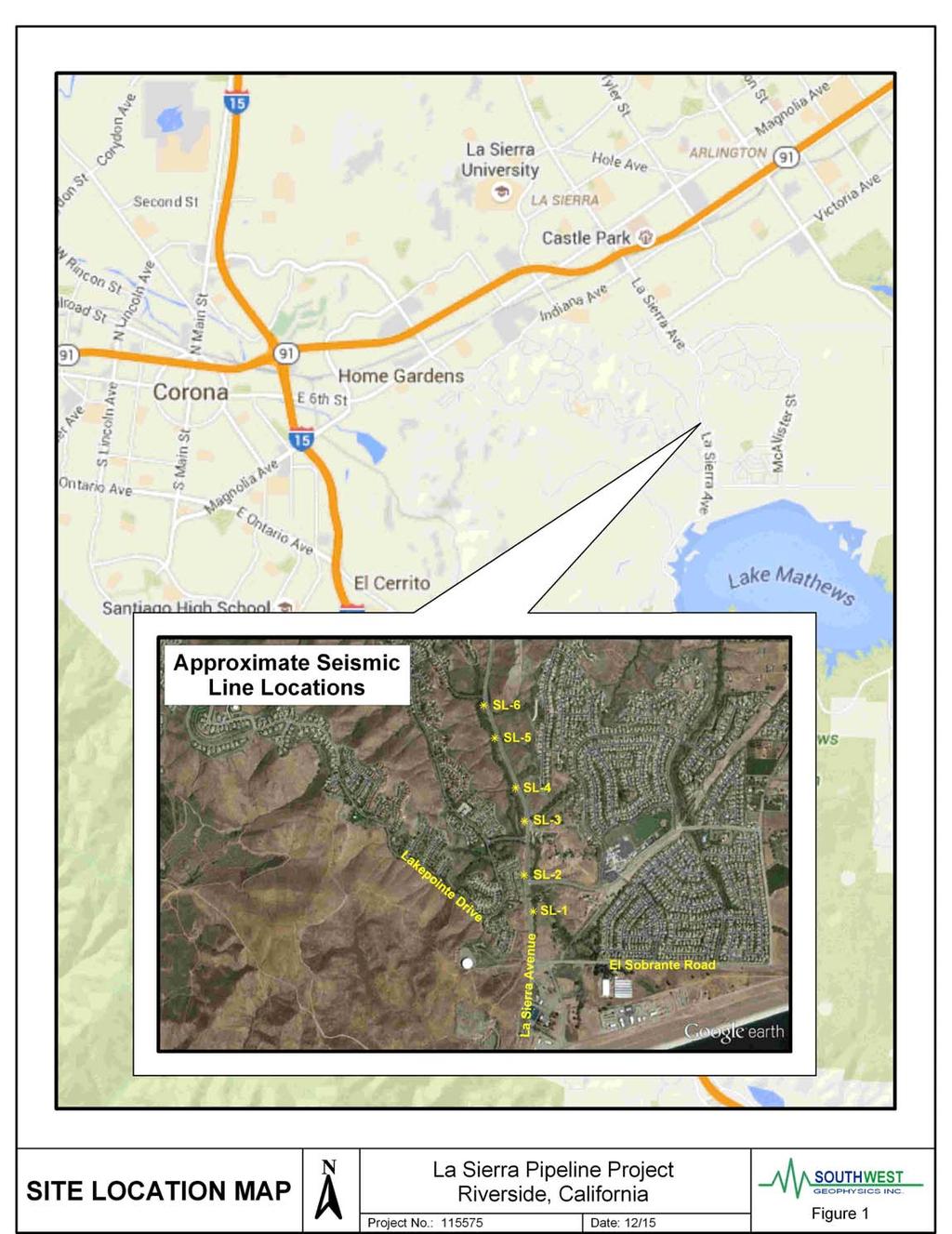
100
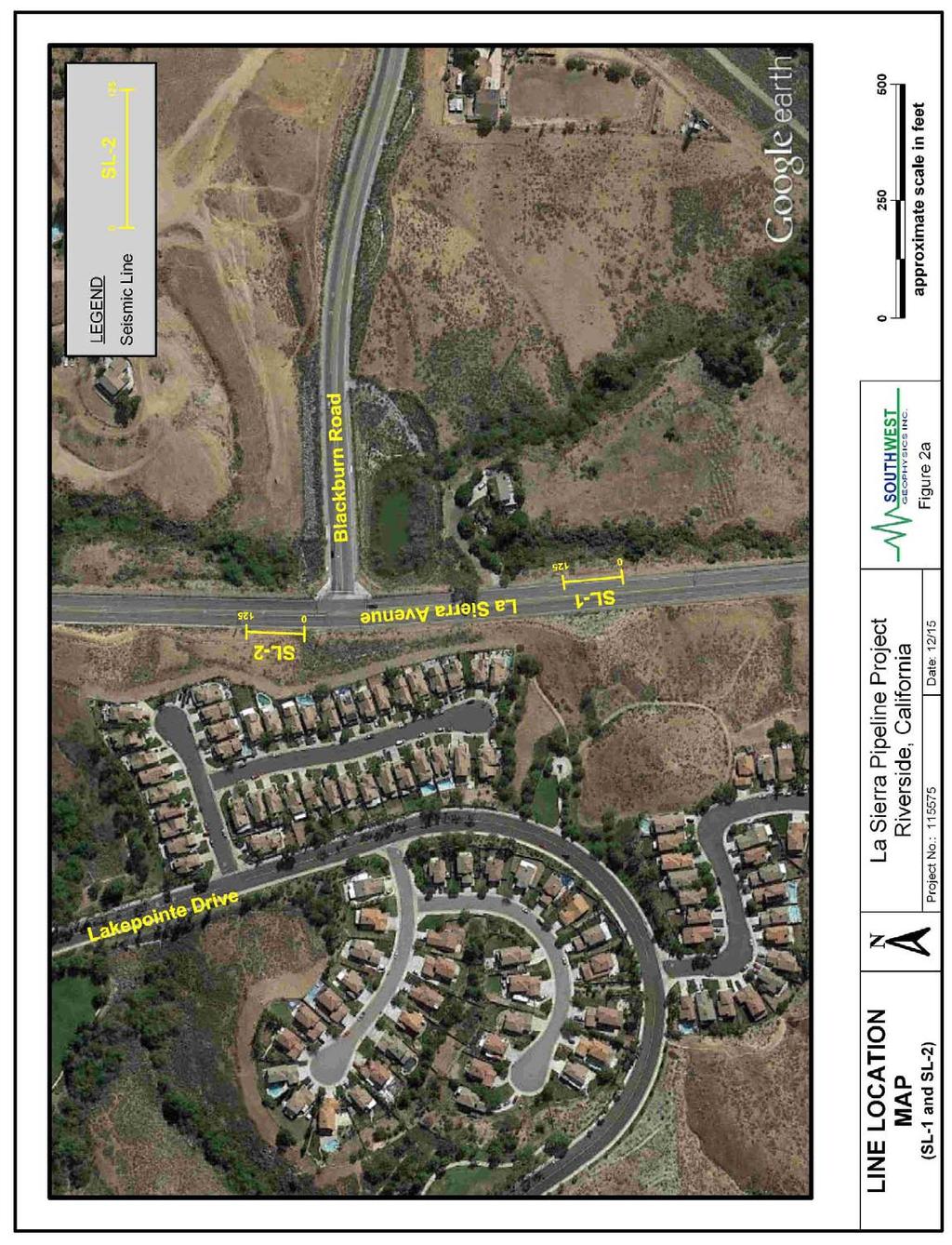
101
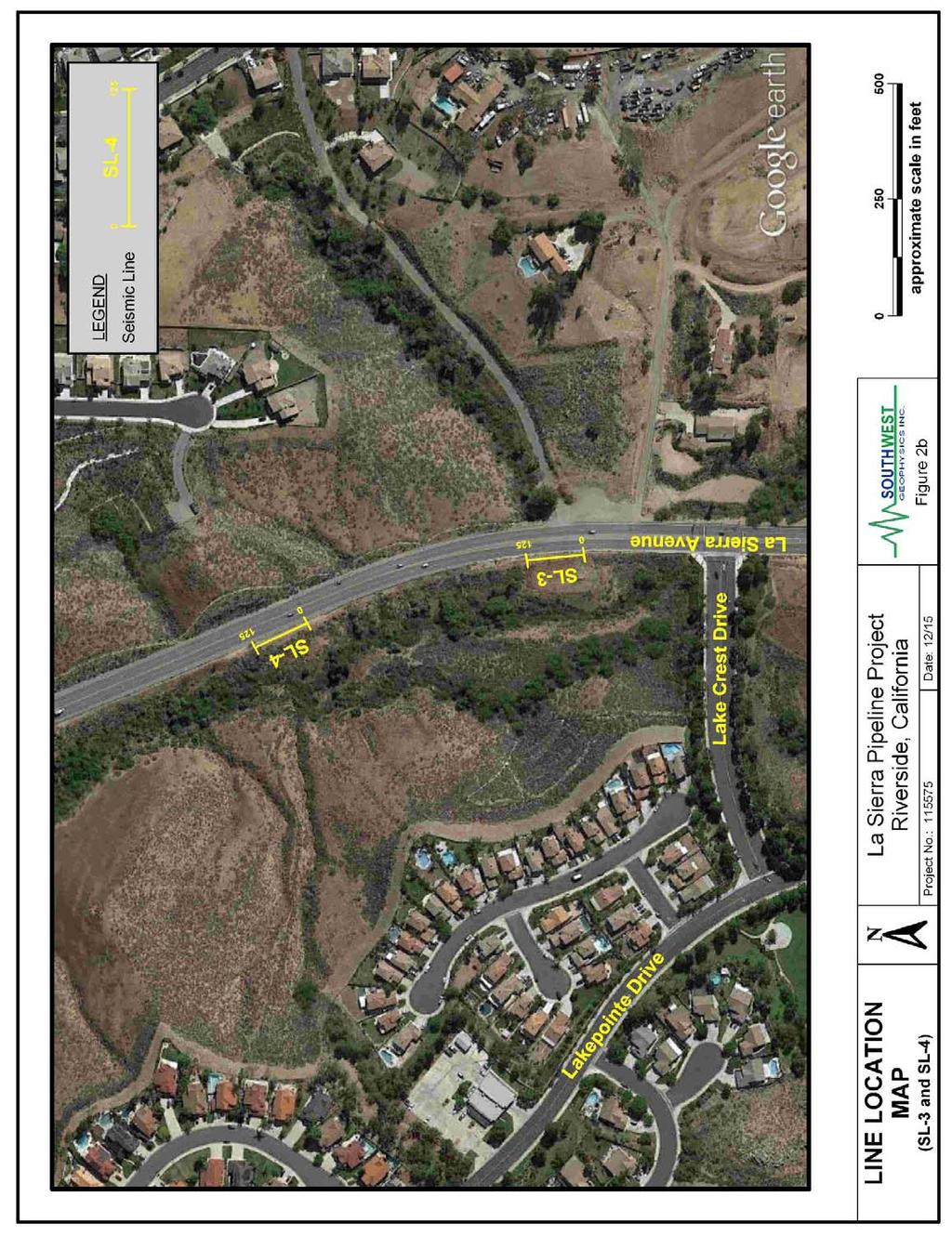
102
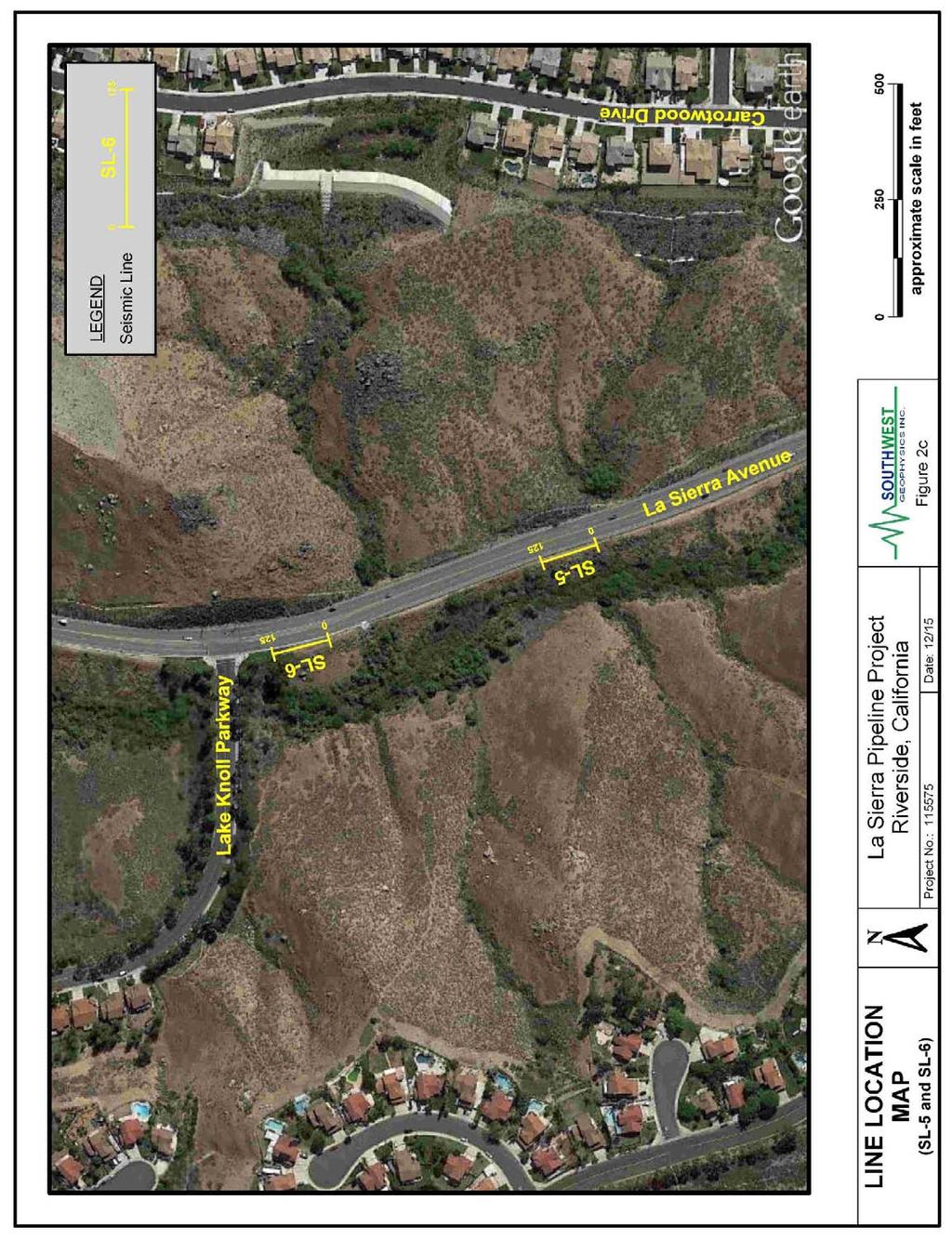
103
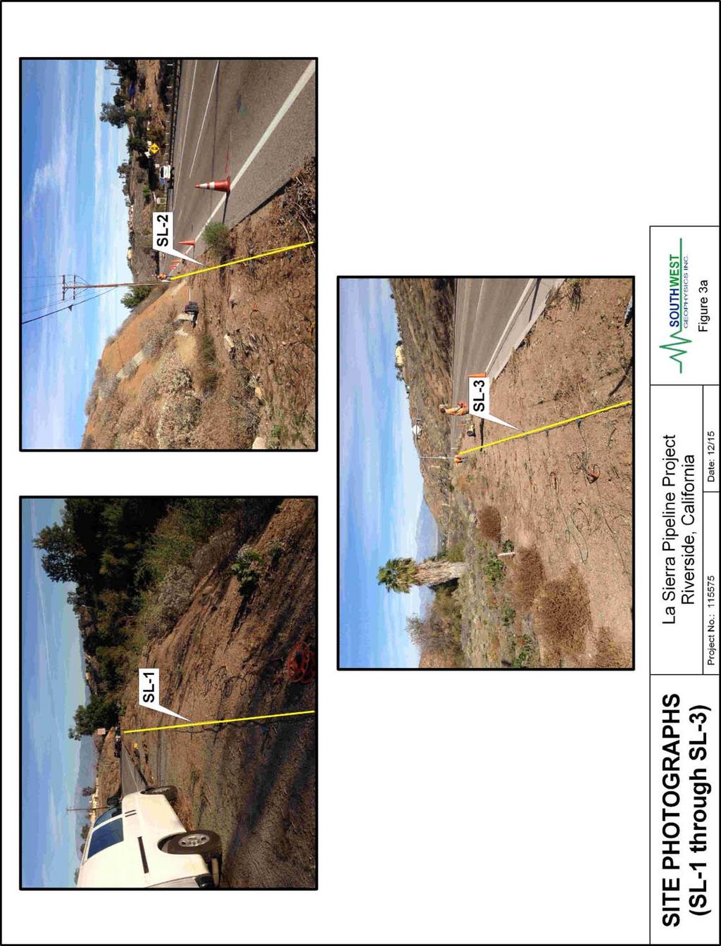
104
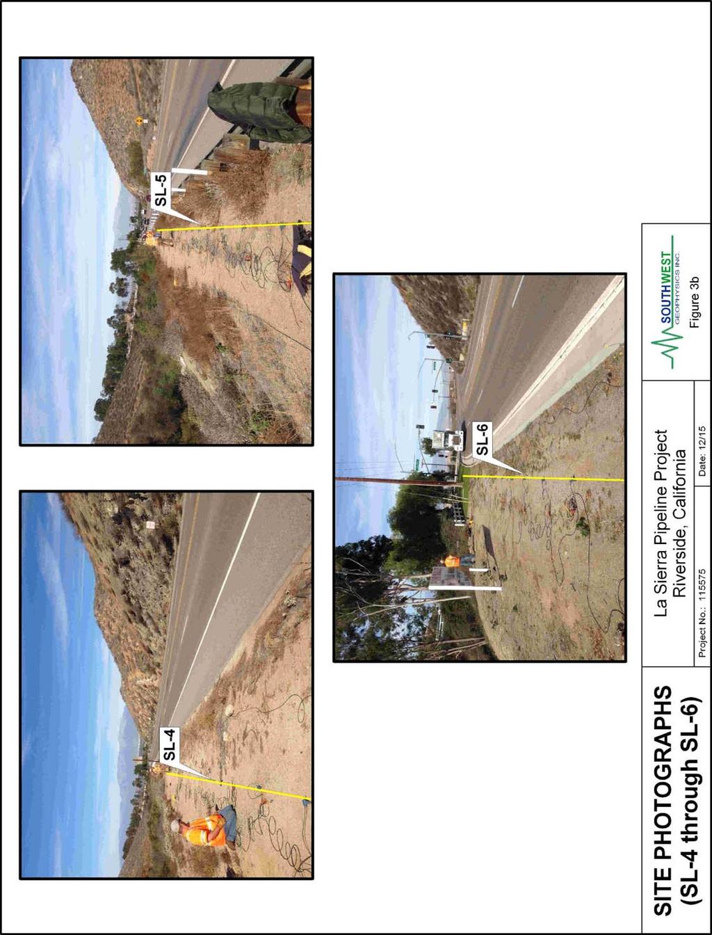
105
106
107
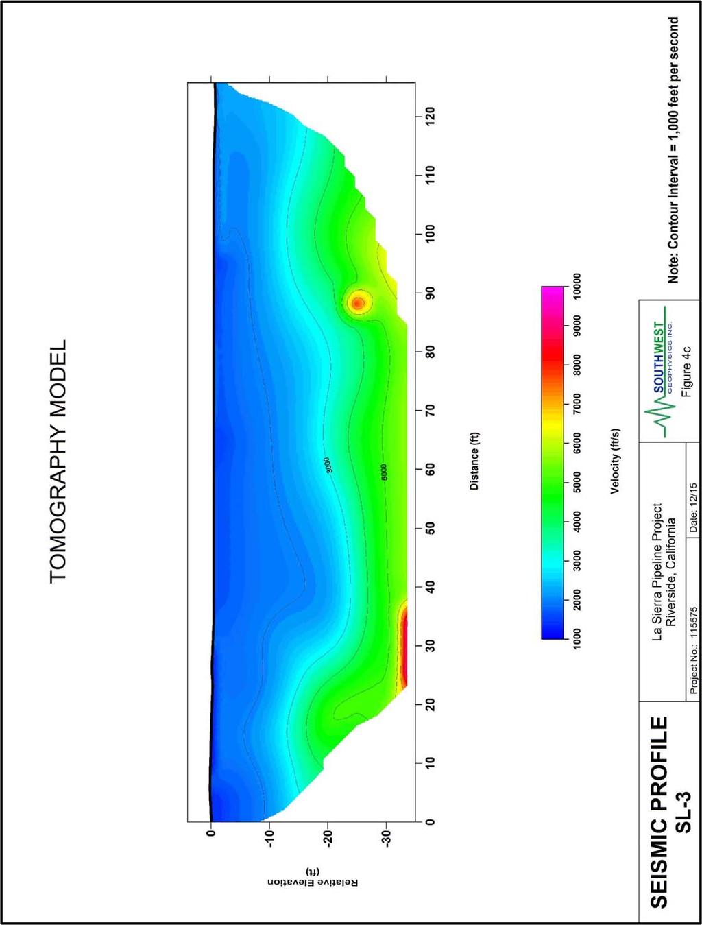
108
109
110
111
112 REVISED GEOTECHNICAL INVESTIGATION REPORT Arlington Desalter Booster Pump Station and Reservoir East End of Sterling Avenue City of Riverside, Riverside County, California Converse Project No February 26, 2016 Prepared For: Albert A. Webb Associates 3788 McCray Street Riverside, CA Prepared By: Corporate Drive Redlands, California 92374
113 Geotechnical Engineering, Environmental & Groundwater Science, Inspection & Testing Services October 19, 2015 Revised February 26, 2016 Mr. Siming Zhang, P.E. Senior Engineer Albert A. Webb Associates 3788 McCray Street Riverside, CA Subject: REVISED GEOTECHNICAL INVESTIGATION REPORT Arlington Desalter Booster Pump Station and Reservoir East End of Sterling Avenue City of Riverside, Riverside County, California Converse Project No Dear Mr. Zhang: (Converse) is pleased to submit this revised geotechnical investigation report to assist with the design and construction of the Western Municipal Water District (WMWD) Arlington Desalter booster pump station and reservoir located within the City of Riverside, Riverside County, California. This report has been modified to incorporate a revised site layout, including a 1.1 MG reservoir. This revised report was prepared in accordance with our proposal dated November 4, 2015 and your Task Order Agreement number dated November 5, Based on our investigation, testing, and analysis, the site is considered suitable from a geotechnical standpoint for the proposed booster station and reservoir provided the recommendations presented herein are incorporated during design and construction. We appreciate the opportunity to be of service to Albert A. Webb Associates and the Western Municipal Water District. If you have any questions, please do not hesitate to contact us at (909) CONVERSE CONSULTANTS Hashmi S. E. Quazi, Ph.D., P.E., G. E. Principal Engineer Dist.: 4/Addressee JB/SM/HSQ/kvg Corporate Drive, Redlands, CA Telephone: (909) Facsimile: (909)
114 PROFESSIONAL CERTIFICATION Revised Geotechnical Investigation Report Arlington Desalter Booster Pump Station and Reservoir City of Riverside, Riverside County, California October 19, 2015 Revised February 26, 2016 Page ii This report has been prepared by the following professionals whose seals and signatures appear hereon. The findings, recommendations, specifications and professional opinions contained in this report were prepared in accordance with the generally accepted professional engineering and engineering geologic principle and practice in this area of Southern California. We make no other warranty, either expressed or implied. M:\JOBFILE\2014\81\ La Sierra Pipeline\Reports\ bps gir rev
115 EXECUTIVE SUMMARY Revised Geotechnical Investigation Report Arlington Desalter Booster Pump Station and Reservoir City of Riverside, Riverside County, California October 19, 2015 Revised February 26, 2016 Page iii The following is a summary of our geotechnical investigation, conclusions and recommendations, as presented in the body of this report. Please refer to the appropriate sections of the report for complete conclusions and recommendations. In the event of a conflict between this summary and the report, or an omission in the summary, the report shall prevail. The approximately 1.09-acre project site is located on the north side of the east end of Sterling Avenue within the City of Riverside, Riverside County, California. The currently undeveloped site is bounded by Sterling Avenue to the south, State Route 91 to the north, commercial/industrial developments to the west, and the Santa Ana Watershed Project and Arlington Desalter facilities to the east. The proposed Arlington Desalter booster pump station will include a pump building, surge tank, and associated piping. The building will house four active and one standby vertical pumps with a total initial capacity of 4,375 gpm, as well as electrical and generator rooms. The proposed 1.1 MG prestressed concrete water reservoir will be approximately 30 feet in height and 86 feet in diameter. The tank floor will be approximately 16 feet below existing grade. Our scope of work included project setup, subsurface exploration, laboratory testing, engineering analysis, and preparation of this report. Two exploratory borings (BH-1 and BH-2) were drilled on September 17, 2015 to their maximum planned depths of 21.5 and 51.5 feet bgs, respectively. Two cone penetrometer test soundings (CPT-1 and CPT-2) were advanced at the proposed reservoir location on November 17, 2015 to depths of 50.5 and 46.1 feet bgs, respectively. The site is underlain to a depth of at least 51.5 feet by alluvial sediments. From the surface to approximately 20 feet bgs, the alluvium consists primarily of sandy silt with scattered thin clay layers. Below 20 feet bgs, the sediments encountered included silt and silty to clayey sand. Groundwater was not encountered in our exploratory borings to a maximum explored depth of 51.5 feet bgs. The historical high groundwater level is approximated to be 36 feet bgs. Groundwater is not expected to be encountered during the construction of this project. M:\JOBFILE\2014\81\ La Sierra Pipeline\Reports\ bps gir rev
116 Revised Geotechnical Investigation Report Arlington Desalter Booster Pump Station and Reservoir City of Riverside, Riverside County, California October 19, 2015 Revised February 26, 2016 Page iv Based on our subsurface exploration, we anticipate that the site soils will be excavatable with conventional heavy duty earthworking and trenching equipment. The project site is not located within a currently designated State of California or Riverside County Earthquake Fault Zone. There are no known active faults projecting toward or extending across the project site. Seismic design parameters for the site and proposed alignments are presented in the text of this report. The site has the potential for liquefaction or dry settlement. The potential for earthquake-induced lateral spreading, landsliding, or flooding at the site is considered low. The site soils have very low expansion potential. The site soils have a slight to moderate collapse potential. The site soils do not contain elevated concentrations of soluble sulfates or chlorides, but are corrosive to ferrous metals. A corrosion engineer should be consulted for the corrosion mitigation measures for ferrous metals in contact with soil. The reservoir footprint should be overexcavated to at least 3 feet below the bottom of the deepest footing. The depth of overexcavation should be uniform across the entire reservoir. The overexcavation should extend laterally at least 3 feet beyond the reservoir footprint. The overexcavation should be deepened as needed to remove any existing fill, and any very soft or saturated soil. Prior to the start of any earthwork, the site should be cleared of all vegetation, existing fill, and debris. The materials resulting from the clearing and grubbing operations should be removed from the site. The building footprint and any other areas to support structures except for the reservoir should be overexcavated to at least 12 inches below the bottom of the footings. The depth of overexcavation should be uniform across the entire structure. The overexcavation should extend at least 2 feet beyond the structure footprint. Pavement and flatwork areas should be overexcavated to a depth of at least 1 foot below subgrade. The overexcavations should extend at least 1 foot beyond the edge of pavement. The overexcavations should be deepened as needed to remove any existing fill, and any very soft or saturated soil. Excavated onsite earth materials cleared of deleterious matter can be moisture conditioned and re-used as compacted fill. M:\JOBFILE\2014\81\ La Sierra Pipeline\Reports\ bps gir rev
117 Revised Geotechnical Investigation Report Arlington Desalter Booster Pump Station and Reservoir City of Riverside, Riverside County, California October 19, 2015 Revised February 26, 2016 Page v Fill soils should be placed on properly prepared excavation bottoms, moisture conditioned, and compacted to at least 90 percent of the laboratory maximum dry density. At least the upper 12 inches of fill beneath pavement intended to support vehicle loads should be compacted to at least 95 percent of the laboratory maximum dry density. The proposed building may be supported by continuous or isolated spread shallow footings. The footings should be at least 18 inches in width and embedded to at least 18 inches below the lowest adjacent grade. The footing reinforcement should be based on structural design. Footings can be designed based on an allowable net bearing capacity of 3,000 pounds per square foot (psf). The total settlement of shallow footings from static structural loads and short-term settlement of properly compacted fill is anticipated to be 0.5 inch or less. The differential settlement resulting from static loads is anticipated to be 0.25 inches or less. The site has the potential for up to 0.3 inches of dynamic settlement during a large earthquake under current groundwater conditions. Dynamic differential settlement under these conditions may be up to approximately 0.2 inches over 50 horizontal feet. If the groundwater level returns to historical high levels from the site vicinity, the potential dynamic settlement may be up to 0.5 inches, and the dynamic differential settlement may be up to approximately 0.5 inches over 50 horizontal feet. Lateral earth pressures, foundation design parameters, and pipeline design parameters are presented in the text of this report. Recommendations for temporary sloped excavations and temporary shoring are provided in the text of this report. Based on our investigation, we believe that the project site is suitable for construction of the proposed booster pump station and reservoir, provided the findings and conclusions presented in this geotechnical investigation report are considered in the planning, design and construction of the project. M:\JOBFILE\2014\81\ La Sierra Pipeline\Reports\ bps gir rev
118 TABLE OF CONTENTS Revised Geotechnical Investigation Report Arlington Desalter Booster Pump Station and Reservoir City of Riverside, Riverside County, California October 19, 2015 Revised February 26, 2016 Page vi 1.0 INTRODUCTION PROJECT DESCRIPTION SITE DESCRIPTION SCOPE OF WORK PROJECT SET-UP SUBSURFACE EXPLORATION LABORATORY TESTING ANALYSIS AND REPORT PREPARATION ENGINEERING GEOLOGY REGIONAL GEOLOGY LOCAL GEOLOGY SUBSURFACE CONDITIONS SUBSURFACE PROFILE GROUNDWATER EXCAVATABILITY SUBSURFACE VARIATIONS LABORATORY TEST RESULTS PHYSICAL TESTING CHEMICAL TESTING - CORROSIVITY EVALUATION FAULTING AND SEISMICITY FAULTING CBC SEISMIC DESIGN PARAMETERS SECONDARY EFFECTS OF SEISMIC ACTIVITY EARTHWORK RECOMMENDATIONS GENERAL REMEDIAL GRADING FILL MATERIALS COMPACTED FILL PLACEMENT SITE DRAINAGE UTILITY TRENCH BACKFILL DESIGN RECOMMENDATIONS GENERAL EVALUATION FOOTING DESIGN PARAMETERS M:\JOBFILE\2014\81\ La Sierra Pipeline\Reports\ bps gir rev
119 Revised Geotechnical Investigation Report Arlington Desalter Booster Pump Station and Reservoir City of Riverside, Riverside County, California October 19, 2015 Revised February 26, 2016 Page vii 10.3 LATERAL EARTH PRESSURES AND RESISTANCE TO LATERAL LOADS SETTLEMENT PIPE DESIGN BEARING PRESSURE FOR ANCHOR AND THRUST BLOCKS SOIL CORROSIVITY CONSTRUCTION RECOMMENDATIONS GENERAL TEMPORARY SLOPED EXCAVATIONS SHORING DESIGN GEOTECHNICAL SERVICES DURING CONSTRUCTION CLOSURE REFERENCES FIGURES Following Page No. Figure No. 1, Site Location Map... 1 Figure No. 2, Approximate Boring and CPT Location Map... 2 Figure No. 3, Recommended Lateral Earth Pressures for Braced Excavation Figure No. 4, Recommended Lateral Earth Pressures on Cantilever Wall TABLES Page No. Table No. 1, Seismic Characteristics of Nearby Active Faults... 8 Table No. 2, CBC Seismic Parameters... 9 Table No. 3, Active and At-Rest Earth Pressures Table No. 4, Soil Parameters for Pipe Design Table No. 5, Slope Ratios for Temporary Excavations APPENDICES Appendix A... Field Exploration Appendix B... Laboratory Testing Program Appendix C... Liquefaction and Settlement Analyses M:\JOBFILE\2014\81\ La Sierra Pipeline\Reports\ bps gir rev
120 Revised Geotechnical Investigation Report Arlington Desalter Booster Pump Station and Reservoir City of Riverside, Riverside County, California February 26, 2016 Page INTRODUCTION This report presents the results of our geotechnical investigation performed for the proposed Arlington Desalter booster pump station (BPS) and water reservoir, located on the north side of the east end of Sterling Avenue, within the City of Riverside, Riverside County, California, as shown in Figure No. 1, Site Location Map. The purposes of this investigation were to determine the nature and engineering properties of the subsurface soils, and to provide design and construction recommendations for the proposed BPS and reservoir. This report is prepared for the project described herein and is intended for use solely by Albert A. Webb Associates, the Western Municipal Water District, and their authorized agents for design purposes. It should not be used as a bidding document but may be made available to the potential contractors for information on factual data only. For bidding purposes, the contractors should be responsible for making their own interpretation of the data contained in this report. 2.0 PROJECT DESCRIPTION The project consists of the design and construction of a 1.1 million-gallon reservoir, pump building, surge tank, and associated piping. Detailed project plans were not available at the time of this report however, a preliminary site layout exhibit was provided (Michael Baker, 2015). We understand that the reservoir will be constructed of pre-stressed concrete and will be approximately 86 feet in diameter, with a height of approximately 30 feet. The reservoir floor will be approximately 16 feet below the existing grade. We anticipate that the reservoir walls will be supported on a continuous ring footing and that the roof columns will be supported by isolated spread footings. We understand that the reservoir footings will be underlain by a minimum of 12 inches of Class 2 aggregate base, and the reservoir floor will be underlain by a minimum of 6 inches of compacted aggregate base. The proposed pump building footprint is approximately 40 feet by 115 feet. We anticipate that the building will be a one-story masonry block wall structure founded on shallow footings with a slab-on-grade. Four active and one standby/rotational vertical pump cans are planned. Each pump is to have a capacity of approximately 1,094 gallons per minute (gpm), for a total initial BPS capacity of 4,375 gpm. The building constructed to house the pump station equipment will also include electrical and generator rooms. The surge tank will be located to the west of the pump building. M:\JOBFILE\2014\81\ La Sierra Pipeline\Reports\ bps gir rev

121 Approximate Site Location Site Location Map Project: Arlington Desalter Booster Pump Station and Reservoir Location: East End of Sterling Avenue, City of Riverside, California Client: Albert A. Webb Associates Project No FIGURE NO. 1
122 Revised Geotechnical Investigation Report Arlington Desalter Booster Pump Station and Reservoir City of Riverside, Riverside County, California February 26, 2016 Page SITE DESCRIPTION The approximately 1.09-acre proposed project site is located on the north side of the east end of Sterling Avenue within the City of Riverside, Riverside County, California. The currently undeveloped site is bounded by Sterling Avenue to the south, State Route 91 to the north, commercial/industrial developments to the west, and the Santa Ana Watershed Project and Arlington Desalter facilities to the east. The site has an approximate elevation of approximately 712 to 714 feet above mean sea level with a slight slope to the west (Michael Baker, 2015). It is covered with gravel and coarsegrained sand with a chain-link fence around the perimeter. 4.0 SCOPE OF WORK The scope of this investigation included set-up, subsurface exploration, laboratory testing, engineering analysis, and preparation of this report, as described in the following sections. 4.1 Project Set-up The project set-up consisted of the following: Preparing a investigation location map for review and approval by Albert A. Webb Associates. Marking the boring and CPT locations in the field such that drill rig access to all the locations was available. Notifying Underground Service Alert (USA) at least 48 hours prior to investigation to clear the locations of any conflict with existing underground utilities. Engaging drilling and CPT subcontractors. 4.2 Subsurface Exploration Two exploratory borings (BH-1 and BH-2) were drilled on September 17, 2015 at the proposed BPS site. The borings were advanced to their maximum planned depths of 21.5 and 51.5 feet bgs respectively. Two cone penetrometer test soundings (CPT-1 and CPT-2) were advanced at the proposed reservoir location on November 17, 2015 to depths of 50.5 and 46.1 feet bgs, respectively. Approximate boring and CPT locations are indicated in Figure No. 2, Approximate Boring and CPT Location Map. For a description of the field exploration and sampling program see Appendix A, Field Exploration. M:\JOBFILE\2014\81\ La Sierra Pipeline\Reports\ bps gir rev


123 BH-1 CPT-2 BH-2 CPT-1 BH-2 CPT-2 Number and Approximate Location of Exploratory Boring Number and Approximate Location of CPT Sounding Approximate Boring and CPT Location Map Project: Arlington Desalter Booster Pump Station and Reservoir Location: East End of Sterling Avenue, City of Riverside, California Client: Albert A. Webb Associates Project No FIGURE NO. 2
IV. ENVIRONMENTAL IMPACT ANALYSIS G. GEOLOGY AND SOILS
 IV. ENVIRONMENTAL IMPACT ANALYSIS G. GEOLOGY AND SOILS The following section is a summary of the geotechnical report conducted for the proposed project. The Report of Geotechnical Investigation Proposed
Impact : Changes to Existing Topography (Less than Significant)
") 4.2 Land Resources 4.2.1 Alternative A Proposed Action Impact 4.2.1-1: Changes to Existing Topography (Less than Significant) Development of the project site would involve grading and other earthwork as
4.2 Land Resources 4.2.1 Alternative A Proposed Action Impact 4.2.1-1: Changes to Existing Topography (Less than Significant) Development of the project site would involve grading and other earthwork as
Converse Consultants Geotechnical Engineering, Environmental & Groundwater Science, Inspection & Testing Services
 Converse Consultants Geotechnical Engineering, Environmental & Groundwater Science, Inspection & Testing Services Ms. Rebecca Mitchell Mt. San Antonio College Facilities Planning & Management 1100 North
Date: April 2, 2014 Project No.: Prepared For: Mr. Adam Kates CLASSIC COMMUNITIES 1068 E. Meadow Circle Palo Alto, California 94303
 City of Newark - 36120 Ruschin Drive Project Draft Initial Study/Mitigated Negative Declaration Appendix C: Geologic Information FirstCarbon Solutions H:\Client (PN-JN)\4554\45540001\ISMND\45540001 36120
IV. ENVIRONMENTAL IMPACT ANALYSIS E. GEOLOGY AND SOILS
 IV. ENVIRONMENTAL IMPACT ANALYSIS E. GEOLOGY AND SOILS The following section is a summary of the geotechnical report conducted for the Proposed Project. The Geotechnical Engineering Investigation (the
IV. ENVIRONMENTAL IMPACT ANALYSIS E. GEOLOGY AND SOILS
 IV. ENVIRONMENTAL IMPACT ANALYSIS E. GEOLOGY AND SOILS INTRODUCTION This section evaluates potential impacts related to geology, including seismicity, and soils associated with development of the proposed
IV. ENVIRONMENTAL IMPACT ANALYSIS E. GEOLOGY AND SOILS
 IV. ENVIRONMENTAL IMPACT ANALYSIS E. GEOLOGY AND SOILS The following analysis is based on the Geotechnical Investigation Report, Proposed Mid-Rise Multi- Family Residential Development Project Wetherly
3.0 SUMMARY OF POTENTIAL GEOTECHNICAL IMPACTS AND MITIGATION MEASURES
 3.0 SUMMARY OF POTENTIAL GEOTECHNICAL IMPACTS AND MITIGATION MEASURES This section summarizes the principal geotechnical conditions that occur in the project area. The potential impact that each condition
IV. ENVIRONMENTAL IMPACT ANALYSIS E. GEOLOGY/SOILS
 IV. ENVIRONMENTAL IMPACT ANALYSIS E. GEOLOGY/SOILS Except where otherwise noted, the following Section is based on the Preliminary Geotechnical Investigation, Proposed Medical Office Buildings and Mixed-Use
SLOPE STABILITY EVALUATION AND ACCEPTANCE STANDARDS
 INFORMATION BULLETIN / PUBLIC - BUILDING CODE REFERENCE NO.: LABC 7006.3, 7014.1 Effective: 01-01-2017 DOCUMENT NO.: P/BC 2017-049 Revised: 12-21-2016 Previously Issued As: P/BC 2014-049 SLOPE STABILITY
ATTACHMENT A PRELIMINARY GEOTECHNICAL SUMMARY
 ATTACHMENT A PRELIMINARY GEOTECHNICAL SUMMARY Kevin M. Martin, P.E. KMM Geotechnical Consultants, LLC 7 Marshall Road Hampstead, NH 0384 603-489-6 (p)/ 603-489-8 (f)/78-78-4084(m) kevinmartinpe@aol.com
GEOLOGY AND SOILS. This chapter summarizes geologic and geotechnical aspects of the site as they relate to the Project.
 9 GEOLOGY AND SOILS INTRODUCTION This chapter summarizes geologic and geotechnical aspects of the site as they relate to the Project. This chapter utilizes information from the following reports prepared
GEOLOGY, SOILS, AND SEISMICITY
 4.9 GEOLOGY, SOILS, AND SEISMICITY 4.9.1 Introduction Information about the geological conditions and seismic hazards in the study area was summarized in the FEIR, and was based on the Geotechnical Exploration
Slope Stability Evaluation Ground Anchor Construction Area White Point Landslide San Pedro District Los Angeles, California.
 Slope Stability Evaluation Ground Anchor Construction Area White Point Landslide San Pedro District Los Angeles, California Submitted To: Mr. Gene Edwards City of Los Angeles Department of Public Works
Geotechnical Engineering Study, Conifer Senior High School Football Field Improvements, Conifer, Colorado
 2390 South Lipan Street Denver, CO 80223 phone: (303) 742-9700 fax: (303) 742-9666 email: kadenver@kumarusa.com www.kumarusa.com Office Locations: Denver (HQ), Colorado Springs, Fort Collins, and Frisco,
Should you have any questions regarding this clarification, please contact the undersigned at or (925)
") October 8, 2015 Revised October 13, 2015 Contra Costa Community College District 500 Court Street Martinez, CA 94553 Attention: Ron Johnson Subject: Clarification of Grading Requirements Diablo Valley
October 8, 2015 Revised October 13, 2015 Contra Costa Community College District 500 Court Street Martinez, CA 94553 Attention: Ron Johnson Subject: Clarification of Grading Requirements Diablo Valley
IV. ENVIRONMENTAL IMPACT ANALYSIS G. GEOLOGY AND SOILS
 IV. ENVIRONMENTAL IMPACT ANALYSIS G. GEOLOGY AND SOILS The following section is based upon the City of El Segundo General Plan and General Plan EIR and addresses the following geologic issues: soil erosion,
Preliminary Geotechnical Evaluation Gooseberry Point Pedestrian Improvements Whatcom County, Washington SITE AND PROJECT DESCRIPTION
 File No. 12-100 Geotechnical & Earthquake Engineering Consultants Mr. Kevin Brown, P.E. Gray & Osborne, Inc. 3710 168 th Street NE, Suite B210 Arlington, Washington 98223 Subject: Draft Report Preliminary
Guidelines for Site-Specific Seismic Hazard Reports for Essential and Hazardous Facilities and Major and Special-Occupancy Structures in Oregon
 Guidelines for Site-Specific Seismic Hazard Reports for Essential and Hazardous Facilities and Major and Special-Occupancy Structures in Oregon By the Oregon Board of Geologist Examiners and the Oregon
Setting MOUNTAIN HOUSE NEIGHBORHOODS I AND J INITIAL STUDY 5. ENVIRONMENTAL CHECKLIST 6. GEOLOGY AND SOILS. Issue
 Issue Less Than Significant or No Impact Potential Significant Impact Adequately Addressed in MEIR MEIR Required Additional Review: No Significant Impact Less Than Significant Impact Due to Mitigation
3.8 Geology/Soils. Environmental Setting. Topography. Geology and Soils
 3.8 Geology/Soils This section examines whether implementation of the 2004 Land Use Mobility Elements, Zoning Code Revisions, and Central District Specific Plan the will expose people or structures to
GEOTECHNICAL EVALUATION ESA SECONDARY CONNECTION PROJECT LAKESIDE, CALIFORNIA PDMWD JN
 GEOTECHNICAL EVALUATION ESA SECONDARY CONNECTION PROJECT LAKESIDE, CALIFORNIA PDMWD JN 214007 PREPARED FOR: RBF Consulting 9755 Clairemont Mesa Boulevard, Suite 100 San Diego, California 92124 PREPARED
Civil Engineering, Surveying and Environmental Consulting WASP0059.ltr.JLS.Mich Ave Bridge Geotech.docx
 2365 Haggerty Road South * Canton, Michigan 48188 P: 734-397-3100 * F: 734-397-3131 * www.manniksmithgroup.com August 29, 2012 Mr. Richard Kent Washtenaw County Parks and Recreation Commission 2330 Platt
 R-1 Conveyor Relocation Project Legend 0 500 1000 1500 ft. This map is a user generated static output from an Internet mapping site and is for general reference only. Data layers that appear on this map
Geotechnical Investigation
 F A M I L Y R E S O U R C E S C E N T E R A N D D I S T R I C T P O L I C E H E A D Q U A R T E R S P R O J E C T I N I T I A L S T U D Y S A N B E R N A R D I N O C I T Y U N I F I E D S C H O O L D I
SLOPE STABILITY EVALUATION AND ACCEPTANCE STANDARDS
 INFORMATION BULLETIN / PUBLIC - BUILDING CODE REFERENCE NO.: LAMC 98.0508 Effective: 1-26-84 DOCUMENT NO. P/BC 2002-049 Revised: 11-1-02 Previously Issued As: RGA #1-84 SLOPE STABILITY EVALUATION AND ACCEPTANCE
2. Initial Summary of Preliminary Expert Opinion of Converse and Psomas Reports
 UNITED WALNUT TAXPAYERS PRELIMINARY REVIEW OF NEGATIVE GEOTECHNICAL AND GEOLOGICAL ASPECTS OF CONSTRUCTING EARTHFILL PAD FOR A SOLAR FARM ON THE WEST PARCEL - DRAFT 1. Introduction A licensed Engineering
IV. ENVIRONMENTAL IMPACT ANALYSIS E. GEOLOGY/SOILS
 IV. ENVIRONMENTAL IMPACT ANALYSIS E. GEOLOGY/SOILS The following discussion is based upon information contained in the Hollywood Redevelopment Plan Amendment EIR and a letter prepared by Geotechnologies,
Mitigation of Liquefaction Potential Using Rammed Aggregate Piers
 ASCE 2011 557 Mitigation of Liquefaction Potential Using Rammed Aggregate Piers R.W. Rudolph, M. ASCE, G.E. 1, B. Serna, M. ASCE, P.E. 2, and T. Farrell, M. ASCE, G.E. 3 1 Principal Consultant, ENGEO,
Northern Colorado Geotech
 PRELIMINARY GEOTECHNICAL ENGINEERING REPORT PROPOSED CECIL FARMS DEVELOPMENT WELD COUNTY ROAD 7, BETWEEN ROADS 7 AND 7 SEVERANCE, COLORADO NORTHERN COLORADO GEOTECH PROJECT NO. 0-6 APRIL 0, 06 Prepared
3.18 GEOLOGY AND SOILS
 3.18 GEOLOGY AND SOILS This section discusses geologic resource concerns as they relate to the environment, public safety, and project design both during construction and after completion of the project.
14 Geotechnical Hazards
 Volume 2: Assessment of Environmental Effects 296 14 Geotechnical Hazards Overview This Chapter provides an assessment of the underlying geotechnical conditions to identify: any potential liquefaction
Pierce County Department of Planning and Land Services Development Engineering Section
 Page 1 of 7 Pierce County Department of Planning and Land Services Development Engineering Section PROJECT NAME: DATE: APPLICATION NO.: PCDE NO.: LANDSLIDE HAZARD AREA (LHA) GEOLOGICAL ASSESSMENT REPORT
4.5 GEOLOGY AND SEISMICITY
 4.5 GEOLOGY AND SEISMICITY INTRODUCTION This section identifies the potential for geologic and seismic hazards to occur on or near the proposed project site. Issues of concern include suitability of soil
CITY OF CAPE CORAL NORTH 2 UTILITIES EXTENSION PROJECT CONTRACT 3
 GEOTECHNICAL REPORT CITY OF CAPE CORAL NORTH UTILITIES EXTENSION PROJECT CONTRACT City of Cape Coral Procurement Division Cultural Park Boulevard, nd Floor Cape Coral, FL ISSUED FOR BID VOLUME of GEOTECHNICAL
Appendix 6A Geologic Information about the Project Area prepared by Ninyo & Moore October 2008
 Appendix 6A Geologic Information about the Project Area prepared by Ninyo & Moore October 2008 Appendix 6A: Geologic Information about the Project Area 6A-1Existing Geologic and Subsurface Conditions
M E M O R A N D U M. Mr. Jonathan K. Thrasher, P.E., Mr. Ian Kinnear, P.E. (FL) PSI
 PSI") M E M O R A N D U M TO: FROM: Mr. Mark Schilling Gulf Interstate Engineering Mr. Jonathan K. Thrasher, P.E., Mr. Ian Kinnear, P.E. (FL) PSI DATE: November 11, 2014 RE: Summary of Findings Geotechnical
M E M O R A N D U M TO: FROM: Mr. Mark Schilling Gulf Interstate Engineering Mr. Jonathan K. Thrasher, P.E., Mr. Ian Kinnear, P.E. (FL) PSI DATE: November 11, 2014 RE: Summary of Findings Geotechnical
4.5 GEOLOGY AND SOILS
 4.5.1 Setting 4.5 GEOLOGY AND SOILS a. Regional Geology. The is located in the south central Santa Cruz Mountains in the heart of the Central Coast ranges of California. This is a seismically active region
SUPPLEMENTARY INVESTIGATION AND LABORATORY TESTING Aggregate Resource Evaluation Proposed Bernand Quarry San Diego County, California
 October 3, 2 Mr. Mark San Agustin Project No. 28-- Home Land Investments Document No. -92 2239 Curlew Street San Diego, CA 92 SUBJECT: SUPPLEMENTARY INVESTIGATION AND LABORATORY TESTING Aggregate Resource
DATA REPORT GEOTECHNICAL INVESTIGATION GALVESTON CRUISE TERMINAL 2 GALVESTON, TEXAS
 DATA REPORT GEOTECHNICAL INVESTIGATION GALVESTON CRUISE TERMINAL 2 GALVESTON, TEXAS SUBMITTED TO PORT OF GALVESTON 123 ROSENBERG AVENUE, 8TH FLOOR GALVESTON, TEXAS 77553 BY HVJ ASSOCIATES, INC. HOUSTON,
ENGINEER S CERTIFICATION OF FAULT AREA DEMONSTRATION (40 CFR )
") PLATTE RIVER POWER AUTHORITY RAWHIDE ENERGY STATION BOTTOM ASH TRANSFER (BAT) IMPOUNDMENTS LARIMER COUNTY, CO ENGINEER S CERTIFICATION OF FAULT AREA DEMONSTRATION (40 CFR 257.62) FOR COAL COMBUSTION RESIDUALS
PLATTE RIVER POWER AUTHORITY RAWHIDE ENERGY STATION BOTTOM ASH TRANSFER (BAT) IMPOUNDMENTS LARIMER COUNTY, CO ENGINEER S CERTIFICATION OF FAULT AREA DEMONSTRATION (40 CFR 257.62) FOR COAL COMBUSTION RESIDUALS
June 9, R. D. Cook, P.Eng. Soils Engineer Special Services Western Region PUBLIC WORKS CANADA WESTERN REGION REPORT ON
 PUBLIC WORKS CANADA WESTERN REGION REPORT ON GEOTECHNICAL INVESTIGATION PROPOSED MARTIN RIVER BRIDGE MILE 306.7 MACKENZIE HIGHWAY Submitted by : R. D. Cook, P.Eng. Soils Engineer Special Services Western
B-1 BORE LOCATION PLAN. EXHIBIT Drawn By: 115G BROOKS VETERINARY CLINIC CITY BASE LANDING AND GOLIAD ROAD SAN ANTONIO, TEXAS.
 N B-1 SYMBOLS: Exploratory Boring Location Project Mngr: BORE LOCATION PLAN Project No. GK EXHIBIT Drawn By: 115G1063.02 GK Scale: Checked By: 1045 Central Parkway North, Suite 103 San Antonio, Texas 78232
Geotechnical Investigation
 2015 Cal Poly Pomona, Portland State University, and others. See full permissions statement at end of document. Civil Engineering Writing Project - Genre Unit 3 Geotechnical Site Investigation Report What
REPORT OF SUBSURFACE INVESTIGATION AND GEOTECHNICAL EVALUATION POTABLE WATER STORAGE TANK REPLACEMENT EL CAPITAN STATE PARK, CALIFORNIA.
 REPORT OF SUBSURFACE INVESTIGATION AND GEOTECHNICAL EVALUATION POTABLE WATER STORAGE TANK REPLACEMENT EL CAPITAN STATE PARK, CALIFORNIA prepared for Winzler & Kelly Consulting Engineers 4180 Ruffin Road,
REPORT OF PRELIMINARY GEOTECHNICAL EXPLORATION
 REPORT OF PRELIMINARY GEOTECHNICAL EXPLORATION ENKA INTERMEDIATE SCHOOL Sand Hill Road Candler, North Carolina Prepared For: BUNCOMBE COUNTY SCHOOLS Prepared By: AMEC ENVIRONMENT & INFRASTRUCTURE, INC.
Earth Mechanics, Inc. Geotechnical & Earthquake Engineering
 TECHNICAL MEMORANDUM EMI PROJECT NO: 13-116 DATE: October 29, 2013 PREPARED FOR: Mr. Todd W. Dudley / AECOM PREPARED BY: SUBJECT: (Raja) S. Pirathiviraj and Lino Cheang / (EMI) Preliminary Foundation Report
Sacramento Modesto Roseville Pleasanton September 19, 2013 Marcia Medina GHD Inc. 417 Montgomery Street, Suite 700 San Francisco, CA Subject: GE
 Sacramento Modesto Roseville Pleasanton September 19, 2013 Marcia Medina GHD Inc. 417 Montgomery Street, Suite 700 San Francisco, CA 94104 Subject: GEOTECHNICAL REPORT AMENDMENT Stonybrook Creek Crossings
APPENDIX E SOILS TEST REPORTS
 Otsego County, NY Site Work Specifications APPENDIX E SOILS TEST REPORTS Blue Wing Services, Inc. July 1, 2010 Blue Wing Services May 20, 2010 Page 2 the site, was not made available to Empire at this
IAEA SAFETY STANDARDS Geotechnical Aspects of Site Evaluation and Foundations in NPPs, NS-G-3.6
 IAEA SAFETY STANDARDS Geotechnical Aspects of Site Evaluation and Foundations in NPPs, NS-G-3.6 Regional Workshop on Volcanic, Seismic, and Tsunami Hazard Assessment Related to NPP Siting Activities and
Geotechnical Investigation Juneau Seawalk - Taku Fisheries to Miner s Wharf Juneau, Alaska DM&A Job No
 Duane Miller & Associates 5821 Arctic Boulevard, Suite A Anchorage, AK 99518-1654 (907) 644-3200 Fax 644-0507 Arctic & Geotechnical Engineering May 4, 2006 Tetra Tech/KCM, Inc. 1971 First Avenue Seattle,
SOUTHERN CALIFORNIA EDISON
 SOUTHERN CALIFORNIA EDISON Geotechnical Investigation Triton 115/12 KV Substation City of Temecula Riverside County, California September 26, 2008 TDBU Civil/Geotechnical Engineering Group GEOTECHNICAL
ENVIRONMENTAL IMPACT ANALYSIS C. GEOLOGY AND SOILS
 IV. ENVIRONMENTAL IMPACT ANALYSIS The following analysis of geology, soils and seismic hazards is based primarily upon the technical report Geotechnical Engineering Investigation Proposed Fashion Square
INVITATION TO BID CITY OF CAPE CORAL SW 6&7 UTILITIES EXTENSION PROJECT CONTRACT VII CENTRAL AREA 6 AND CENTRAL AREA 8 ITB UT13-02/TM-G
 GEOTECHNICAL REPORT INVITATION TO BID CITY OF CAPE CORAL SW 6&7 UTILITIES EXTENSION PROJECT CONTRACT VII CENTRAL AREA 6 AND CENTRAL AREA 8 ITB UT13-02/TM-G City of Cape Coral Procurement Division 1015
ENCE 3610 Soil Mechanics. Site Exploration and Characterisation Field Exploration Methods
 ENCE 3610 Soil Mechanics Site Exploration and Characterisation Field Exploration Methods Geotechnical Involvement in Project Phases Planning Design Alternatives Preparation of Detailed Plans Final Design
SURFACE GEOLOGY AND LIQUEFACTION SUSCEPTIBILITY IN THE INNER RIO GRANDE VALLEY NEAR ALBUQUERQUE, NEW MEXICO
 SURFACE GEOLOGY AND LIQUEFACTION SUSCEPTIBILITY IN THE INNER RIO GRANDE VALLEY NEAR ALBUQUERQUE, NEW MEXICO Keith I. Kelson, Christopher S. Hitchcock, and Carolyn E. Randolph William Lettis & Associates,
REPORT PRELIMINARY GEOTECHNICALINVESTIGATION. Proposed Pacific Center Development Anaheim, California
 REPORT PRELIMINARY GEOTECHNICALINVESTIGATION Proposed Pacific Center Development Anaheim, California PREPARED FOR 4000 MacArthur Boulevard, Suite 1 Newport Beach, CA 92660 PREPARED BY NOVA Services, Inc.
GEOTECHNICAL STUDY REPORT PROPOSED WATER STORAGE TANK WATER SYSTEM IMPROVEMENT WALNUT GROVE, CALIFORNIA. Prepared for: MWH AMERICAS INC.
 GEOTECHNICAL STUDY REPORT PROPOSED WATER STORAGE TANK WATER SYSTEM IMPROVEMENT WALNUT GROVE, CALIFORNIA Prepared for: MWH AMERICAS INC Prepared by: NOVEMBER 2012 GEOTECHNICAL STUDY REPORT PROPOSED WATER
3E. Geology and Soils
 INTRODUCTION The purpose of this chapter is to evaluate the proposed project s impacts on local geological features and whether it would expose people or structures to adverse geological impacts. Potential
Converse Consultants Geotechnical Engineering, Environmental & Groundwater Science, Inspection & Testing Services
 Converse Consultants Geotechnical Engineering, Environmental & Groundwater Science, Inspection & Testing Services July 27, 2017 Ms. Rebecca Mitchell Mt. San Antonio College Facilities Planning & Management
Downtown Anchorage Seismic Risk Assessment & Land Use Regulations to Mitigate Seismic Risk
 Prepared for: The Municipality of Anchorage Planning Department and the Geotechnical Advisory Commission Downtown Anchorage Seismic Risk Assessment & Land Use Regulations to Mitigate Seismic Risk Prepared
Geology, Soils, and Seismicity
 Section 3.8 Geology, Soils, and Seismicity Introduction This section generally evaluates the effects of the alternatives analyzed in this Supplemental DEIS with regard to geology, soils and seismicity.
5.11 Geology and Soils
 5.11 Geology and Soils 5.11 GEOLOGY AND SOILS This section evaluates the geologic and seismic conditions within the City of Azusa and evaluates the potential for geologic hazard impacts associated with
CEMEX Eliot Quarry. Lake A Evaluation Report. Alameda County, California
 May 7, 2015 May 7, 2015 Project No. GT13-16 Prepared for: CEMEX 5180 Golden Foothills, Parkway El Dorado Hills, California 95762 7400 Shoreline Drive, Ste. 6 Stockton, California 95219 Tel: 209-472-1822
Seismic Reflection Imaging across the Johnson Ranch, Valley County, Idaho
 Seismic Reflection Imaging across the Johnson Ranch, Valley County, Idaho Report Prepared for the Skyline Corporation Lee M. Liberty Center for Geophysical Investigation of the Shallow Subsurface (CGISS)
Limited Geotechnical Engineering Evaluation Classroom Additions Albany County Campus Laramie, Wyoming
 Limited Geotechnical Engineering Evaluation Classroom Additions Albany County Campus 2300 Missile Drive, Cheyenne, Wyoming 82001 Phone 307-635-0222 www.stratageotech.com Limited Geotechnical Engineering
10. GEOTECHNICAL EXPLORATION PROGRAM
 Geotechnical site investigations should be conducted in multiple phases to obtain data for use during the planning and design of the tunnel system. Geotechnical investigations typically are performed in
9. GEOLOGY, SOILS, AND MINERALS
 June 28, 2018 Page 9-1 9. GEOLOGY, SOILS, AND MINERALS This EIR chapter describes the existing geological, soil, and mineral conditions in the planning area. The chapter includes the regulatory framework
IV. ENVIRONMENTAL IMPACT ANALYSIS E. GEOLOGY/SEISMIC HAZARDS
 IV. ENVIRONMENTAL IMPACT ANALYSIS E. GEOLOGY/SEISMIC HAZARDS 1. ENVIRONMENTAL SETTING The following analysis of geology and seismic hazards for the Middle School Project is based on the Report of Geotechnical
APPENDICES. Appendix A City Standard Details Appendix B Engineering Geology Report
 APPENDICES Appendix A City Standard Details Appendix B Engineering Geology Report APPENDIX A CITY STANDARDS DETAILS APPENDIX B ENGINEERING GEOLOGY REPORT ENGINEERING GEOLOGY REPORT WATER
Appendix B. Geotechnical Investigation
 Appendix B Geotechnical Investigation PRELIMINARY GEOTECHNICAL INVESTIGATION PROPOSED REGAL CINEMAS WESTFIELD NORTH COUNTY SHOPPING CENTER ESCONDIDO, CALIFORNIA Prepared for: WESTFIELD, LLC 2049 Century
USE OF GEOPHYSICAL SURVEYS FOR FILL CHARACTERIZATION AND QUANTITY ESTIMATION AT BROWNFIELD SITES A CASE HISTORY. Abstract
 USE OF GEOPHYSICAL SURVEYS FOR FILL CHARACTERIZATION AND QUANTITY ESTIMATION AT BROWNFIELD SITES A CASE HISTORY John A. Mundell, Mundell & Associates, Inc., Indianapolis, IN Gregory B. Byer, Mundell &
TABLE OF CONTENTS /FLD7R Kleinfelder
 TABLE OF CONTENTS CHAPTER PAGE 1 INTRODUCTION 1 1.1 Proposed Construction 1 1.2 Purpose and Scope of Services 2 1.2.1 Geologic and Seismic Hazards 2 1.2.2 Geotechnical Engineering Exploration 3 2 SITE
GEOTECHNICAL ENGINEERING II. Subject Code : 06CV64 Internal Assessment Marks : 25 PART A UNIT 1
 GEOTECHNICAL ENGINEERING II Subject Code : 06CV64 Internal Assessment Marks : 25 PART A UNIT 1 1. SUBSURFACE EXPLORATION 1.1 Importance, Exploration Program 1.2 Methods of exploration, Boring, Sounding
DRILLED DISPLACMENT PILE PERFORMANCE IN COASTAL PLAIN AND RESIDUAL SOILS
 DRILLED DISPLACMENT PILE PERFORMANCE IN COASTAL PLAIN AND RESIDUAL SOILS Presented by: W. Morgan NeSmith, P.E. Berkel & Company Contractors Inc. 770.941.5100 mnesmith@berkelapg.com SC Engineering Conference
December 5, Junction Gateway, LLC 7551 W. Sunset Boulevard #203 Los Angeles, CA Mr. James Frost P: Dear Mr.
 December 5, 2014 Junction Gateway, LLC 7551 W. Sunset Boulevard #203 90046 Attn: Re: Mr. James Frost P: 323.883.1800 Geotechnical Update Letter Sunset & Effie Mixed Use Development 4301 to 4311 Sunset
February 22, 2016 AG File No
 Ainley Graham & Associates Limited 1-50 Grant Timmins Drive, Kingston, Ontario, K7M 8N2 Tel: (343) 266-0002 Fax: (343) 266-0028 E-mail Kingston@ainleygroup.com February 22, 2016 AG File No. 15062-1 Ministry
4.9 GEOLOGY AND SOILS
 4.9 GEOLOGY AND SOILS 4.9.1 EXISTING CONDITIONS TOPOGRAPHY AND RELIEF Zone 40 is located in the central portion of Sacramento County. The topography of the county is represented by three physiographic
J. Paul Guyer, P.E., R.A.
 J. Paul Guyer, P.E., R.A. Paul Guyer is a registered mechanical engineer, civil engineer, fire protection engineer and architect with over 35 years experience in the design of buildings and related infrastructure.
GEOTECHNICAL EVALUATION CHAPEL HILLS WATER CAMPUS MALLARD DRIVE AND STATE ROUTE 179 SEDONA, ARIZONA
 GEOTECHNICAL EVALUATION CHAPEL HILLS WATER CAMPUS MALLARD DRIVE AND STATE ROUTE 179 SEDONA, ARIZONA PREPARED FOR: Arizona Water Company 7580 North Dobson Road, Suite 200 Scottsdale, Arizona 85256 PREPARED
 Photo 1 - Southerly view across 2700 parking lot toward existing building. Multi-residential building borders western side of property in upper right of view. Photo 2 - Southerly view across 2750 parking
An Introduction to Field Explorations for Foundations
 An Introduction to Field Explorations for Foundations J. Paul Guyer, P.E., R.A. Paul Guyer is a registered mechanical engineer, civil engineer, fire protection engineer and architect with over 35 years
Geotechnical Evaluation
 Geotechnical Evaluation Neighborhood No. 1 Sewer Pump Station Replacement 16106 4S Ranch Parkway San Diego, California Infrastructure Engineering Corporation 14271 Danielson Street San Diego, California
FRIENDS OF THE EEL RIVER
 FRIENDS OF THE EEL RIVER Working for the recovery of our Wild & Scenic River, its fisheries and communities. Frank Blackett, Regional Engineer Office of Energy Projects Division of Dam Safety and Inspections
Geotechnical Geologic Coastal Environmental
 Geotechnical Geologic Coastal Environmental 26590 Madison Avenue Murrieta, California 92562 (951) 677-9651 FAX (951) 677-9301 www.geosoilsinc.com April 22, 2014 c/o Matthew Fagan Consulting Services 42011
STRUCTURAL STABILITY ASSESSMENT
 STRUCTURAL STABILITY ASSESSMENT CFR 257.73(d) Bottom Ash Pond Complex Cardinal Plant Brilliant, Ohio October, 2016 Prepared for: Cardinal Operating Company Cardinal Plant Brilliant, Ohio Prepared by: Geotechnical
Appendix D Rock Blasting Report
 Appendix D Rock Blasting Report 02-2500-01 May 20, 2005 Frank Arciero Jr. Fallingstar Homes 27231 Burbank Foothill Ranch, California 92610 Subject: ANTICIPATED ROCK EXCAVATION FRAZIER PARK ESTATES DEVELOPMENT
REPORT NO 12/115/D NOVEMBER 2012 GEOTECHNICAL INVESTIGATION FOR THE PROPOSED SOLAR PHOTOVOLTAIC FACILITY, GROOTVLEI POWER STATION
 Consulting Geotechnical Engineers & Engineering Geologists P.O.Box 3557 Cramerview 2060. Tel: (011) 465-1699. Fax: (011) 465-4586. Cell 082 556 7302 & 076 966 8445 REPORT NO 12/115/D NOVEMBER 2012 GEOTECHNICAL
APPENDIX B GEOTECHNICAL INVESTIGATION
 APPENDIX B GEOTECHNICAL INVESTIGATION INTENTIONALL LEFT BLANK GEOTECHNICAL INVESTIGATION 2016 SEWER AND WATER GROUP 1 CIP, WATER PROJECT 1 15 TH STREET AND AVENIDA PRIMAVERA DEL MAR, CALIFORNIA PREPARED
Roy Pyle March 24, 2017 Chief Facilities Planner Contra Costa Community College District 500 North Court Street Martinez, CA 94533
 State of California Natural Resources Agency Edmund G. Brown Jr., Governor Department of Conservation John G. Parrish, Ph.D., State Geologist California Geological Survey 801 K Street MS 12-31 Sacramento,
SITE INVESTIGATION 1
 SITE INVESTIGATION 1 Definition The process of determining the layers of natural soil deposits that will underlie a proposed structure and their physical properties is generally referred to as site investigation.
IV. ENVIRONMENTAL IMPACT ANALYSIS C. GEOLOGY/SOILS
 IV. ENVIRONMENTAL IMPACT ANALYSIS C. GEOLOGY/SOILS The following section is a summary of the preliminary geotechnical consultation conducted for the Proposed Project. The Report of Geotechnical Engineering
4.5 GEOLOGY AND SOILS
 4.5 GEOLOGY AND SOILS This section addresses the project site geology and soils and analyzes potential changes that would result from development of the Wye Specific Plan project. 4.5.1 Environmental Setting
IV. ENVIRONMENTAL IMPACT ANALYSIS G. GEOLOGY AND SOILS
 IV. ENVIRONMENTAL IMPACT ANALYSIS G. GEOLOGY AND SOILS INTRODUCTION The information and analysis in this section is based primarily on the following report, which is included in Appendix IV.G of this EIR:
The results of KCB s site inspection observations and our recommendations for further work are presented herein.
 July 14, 2015 Central Region 401, 4902 51 Street Red Deer, Alberta T4N 6K8 Mr. Tony Penney, P.Eng. Construction Engineer Dear Mr. Penney: June 25, 2015 Site Inspection Report The above site was visited
R.M.HARW & ASSOCIATES LTD. GEOTECHNICAL INVESTIGATION PROPOSED BRIDGE SITE. HELAVA CREEKl MILE MACKENZIE HIGHWAY E-2510 OCTOBER 16, 1973
 El R.M.HARW & ASSOCIATES LTD. GEOTECHNICAL INVESTIGATION PROPOSED BRIDGE SITE HELAVA CREEKl MILE 616.4 MACKENZIE HIGHWAY E-2510 OCTOBER 16, 1973 R,M,HARDV & ASSOCIATES LTD. CONSULTING ENGINEERING & TESTING
3.10 GEOLOGY AND SOILS
 3.10 GEOLOGY AND SOILS This section evaluates the potential impacts of the proposed project on geology, soils, and seismic hazards. This evaluation is based on the Preliminary Geotechnical Investigation
4.4 GEOLOGY AND SOILS
 4.4 GEOLOGY AND SOILS This section analyzes potential geotechnical hazards that may adversely affect the project site or that may be exacerbated by implementation of the proposed project. Information presented
4.5 GEOLOGY, SOILS AND SEISMICITY
 4.5 This section summarizes information on geology, soils and seismic hazards, and mineral resources in the Truckee area, as well as potential area-wide geologic hazards and regional seismic characteristics
Mass Wasting. Revisit: Erosion, Transportation, and Deposition
 Mass Wasting Revisit: Erosion, Transportation, and Deposition While landslides are a normal part of erosion and surface processes, they can be very destructive to life and property! - Mass wasting: downslope