CERRO RESERVOIR DRAWDOWN PLAN
|
|
|
- Gyles Chapman
- 5 years ago
- Views:
Transcription
1 GEOTECHNICAL AND WATER RESOURCES ENGINEERING CERRO RESERVOIR DRAWDOWN PLAN CERRO RESERVOIR OUTLET WORKS REPLACEMENT PROJECT MONTROSE COUNTY, COLORADO Submitted to City of Montrose 433 South First Street Montrose, Colorado Submitted by RJH Consultants, Inc Mt. Pyramid Court, Suite 330 Englewood, Colorado May 2018 Project Michael L. Graber, P.E. Project Manager
2 Cerro Reservoir Drawdown Plan Cerro Reservoir Outlet Works Replacement Project May 2018 TABLE OF CONTENTS TABLE OF CONTENTS... I SECTION 1 - INTRODUCTION PURPOSE GENERAL DESCRIPTION OF THE SITE DAM CONSTRUCTION AND MODIFICATION HISTORY Western Dam Southern Dam Eastern Dam SUBSURFACE DATA AND EXISTING SEEPAGE CONDITIONS Presently Available Geologic and Geotechnical Information Seepage Conditions... 4 SECTION 2 - RESERVOIR DRAWDOWN PLAN GENERAL COORDINATION SCHEDULE... 5 SECTION 3 - DRAWDOWN BY SIPHON GENERAL SIPHON DESIGN ACTIVATING AND DEACTIVATING THE SIPHON AND MAINTENANCE... 8 SECTION 4 - DRAWDOWN BY PUMP GENERAL SYSTEM COMPONENTS SECTION 5 - EMBANKMENT MONITORING DURING DRAWDOWN RAPID DRAWDOWN FAILURE MODE GENERAL EMBANKMENT MONITORING RESERVOIR LEVEL MONITORING EMBANKMENT INSPECTION i Cerro Reservoir Drawdown Plan
3 Cerro Reservoir Drawdown Plan Cerro Reservoir Outlet Works Replacement Project May REPORTING SECTION 6 - CONTINGENCY PLAN SECTION 7 - REFERENCES LIST OF FIGURES Figure 2.1 Elevation-Area-Capacity Curve Figure 3.1 Siphon Approximate Rating Curve APPENDICES Appendix A Appendix B Appendix C Appendix D Tentative Schedule and Discharge Rates Inspection Forms Siphon Design Drawings Existing Construction Information ii Cerro Reservoir Drawdown Plan
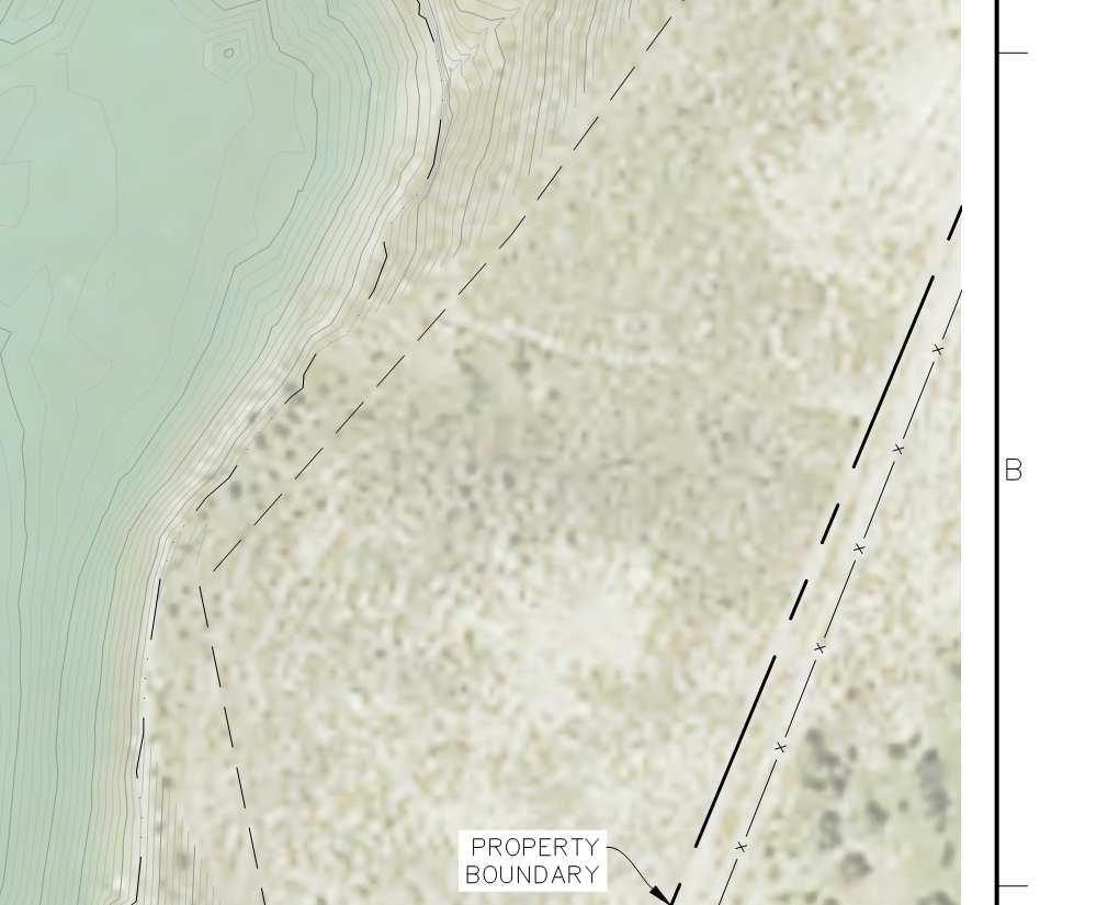
4 Cerro Reservoir Drawdown Plan Cerro Reservoir Outlet Works Replacement Project May 2018 SECTION 1 - INTRODUCTION 1.1 Purpose The purpose of this Reservoir Drawdown Plan (Plan) is to provide recommendations for drawdown of Cerro Reservoir (aka Montrose Reservoir) (DAMID ) located in Montrose County, Colorado. The reservoir will be lowered from the approximate maximum normal water surface elevation to the reservoir bottom, effectively draining the reservoir. The reservoir is being drained to facilitate construction of The Cerro Outlet Works Replacement Project (Project), which requires excavation and replacement of a portion of the western embankment. This Plan includes a schedule for reservoir drawdown, reservoir elevation-capacity data, siphon construction and operation details, pump operation details, recommendations for monitoring and inspection during drawdown, and contingency plans. 1.2 General Description of the Site Cerro Reservoir Dam is a high hazard dam owned and operated by the City of Montrose (City) located approximately 14 miles east of Montrose, Colorado along Highway 50. The dam impounds a 720 acre-foot (ac-ft) reservoir at the maximum normal water level (NWL) elevation (El.) Based on survey data from April 2018, the reservoir is at or below El The reservoir is impounded by three earthen embankment dams: a western embankment, a southern embankment, and an eastern embankment. The outlet works is located through the western embankment and the spillway is located on the left abutment of the eastern embankment. The invert of the auxiliary spillway is at El The reservoir is filled by a 24-inch-diameter diversion pipeline that discharges into the reservoir at the left abutment of the southern embankment at El The Vernal Mesa Canal (aka Cimarron Canal) (Canal) traverses the Site from south to north and is generally located west of the western embankment. The Vernal Mesa Canal Company (Canal Company) owns and operates the Canal and maintains a residence and appurtenances downstream of the western embankment. A map of the Site location and plan of the Reservoir are presented on the construction drawings in Appendix C. 1.3 Dam Construction and Modification History The west and south embankments were constructed prior to 1953 and original construction records are not available. The reservoir was enlarged in 1953 and the outlet Cerro Reservoir Drawdown Plan
5 Cerro Reservoir Drawdown Plan Cerro Reservoir Outlet Works Replacement Project May 2018 works was modified in conjunction with the enlargement (C-644, 1953). It is our understanding that the 1953 modifications included the following components: A 10-foot vertical raise to the west and south earth embankments. Construction of the east embankment. An enlarged auxiliary spillway at the left abutment with a loose-placed riprap control section and earthen channel. Abandonment of the existing auxiliary spillway located at the right abutment of the west embankment. Additional upstream slope protection. Modifications to the outlet works. In 1966, the reservoir basin was enlarged by excavating material located in the northeast portion of the reservoir basin (C-644A, 1966). Excavated material was designed to be stockpiled north and west of the west dam embankment. Drawings from the original enlargement are included in Appendix D. The Project drawings appear to be as-builts and, based on RJH field observations and discussions with the City, the drawings do not completely reflect as-constructed conditions at the dam. A summary of the embankments is provided below. Embankment dimensions were generalized from embankment enlargement drawings (C-644, 1953) and Survey data (Del-Mont, 2017) Western Dam The original western dam was approximately 370 feet long and 16 feet tall. Following the 1954 enlargement, the dam was approximately 520 feet long and 26 feet tall with a 15-foot-wide crest, and 2 horizontal to 1 vertical (2H:1V) upstream and downstream slopes. The upstream slope is approximately 3H:1V below the maximum NWL. New fill was designed to be keyed into the existing dam crest with a 4-foot-deep by 6- foot-wide core trench. Between Station 1+25 and Station 4+50, new fill was also designed to be keyed into the existing foundation with a 4-foot-deep (minimum) by 10- foot-wide core trench Cerro Reservoir Drawdown Plan
6 Cerro Reservoir Drawdown Plan Cerro Reservoir Outlet Works Replacement Project May Southern Dam The original southern dam was approximately 520 feet long and 38 feet tall. Following the 1954 enlargement, the dam was approximately 800 feet long and 53 feet tall with a 16-foot-wide crest and 2H:1V upstream and downstream slopes. The upstream slope is approximately 3H:1V below the maximum NWL. A core trench was not designed to be constructed at the south dam but a requirement was included to remove vegetation and corrugate the downstream slope prior to placing new fill. An aggregate toe drain is located at the maximum embankment section, which was designed to be connected to a granular drain trench that discharges downstream of the dam. The granular trench drain was designed to consist of a layer of well graded gravel around select rubble material. As shown on the drawings in Appendix D, the select rubble is in contact with foundation soils. Gradations are not available for these materials and the outfall location of the drain is unknown Eastern Dam The eastern dam was constructed in 1953 and consists of an approximate 280-foot-long, 10-foot-tall embankment with an 11-foot-wide crest and 2H:1V upstream and downstream slopes. New fill at the eastern dam was designed to be keyed into foundation soils with a 4-footdeep (minimum) by 10-foot-wide core trench. 1.4 Subsurface Data and Existing Seepage Conditions Presently Available Geologic and Geotechnical Information According to published maps (Steven and Hail, 1989; Dickinson, 1963), the Project site consists of Quaternary-age (less than 2.6 million years old) landslide soil deposits overlying Upper Cretaceous aged Mancos Shale (between 99.6 and 65.5 million years ago). Landslide deposits are expected to consist of heterogeneous deposits of material formed largely by repeated complex slump, mudflow, earthflow, and rockfall movements. The thickness of the landslide deposits are currently unknown. Mancos Shale typically consists of dark-gray to black, sandy, silty, and calcareous shale Cerro Reservoir Drawdown Plan
7 Cerro Reservoir Drawdown Plan Cerro Reservoir Outlet Works Replacement Project May 2018 In 2017, RJH collected soil samples from the eastern dam and the western dam in the vicinity of existing point source seepages. Recovered material consisted of mostly medium to high plasticity fines with between 4 and 21 percent sand. In 2018, RJH excavated test pits around the reservoir basin and advanced borings at and downstream of the western embankment. The data report summarizing these efforts is ongoing but embankment and foundation materials typically consisted of medium to high plasticity fines with minimal sand-sized particles Seepage Conditions Based on the 2017 Engineer s Inspection Report (SEO, 2017), active seepage was identified at the toe of the western dam and eastern dam, and active seepage was not identified downstream of the southern dam. Seepage conditions generally consist of relatively low gradient point source seepage flowing at a trickle. Additionally, boggy conditions typically persist downstream of the eastern dam Cerro Reservoir Drawdown Plan
8 Cerro Reservoir Drawdown Plan Cerro Reservoir Outlet Works Replacement Project May 2018 SECTION 2 - RESERVOIR DRAWDOWN PLAN 2.1 General The drawdown plan consists of slowly lowering the reservoir according to the drawdown schedule in this Plan and monitoring the slopes of the reservoir for signs of displacement or instability. Approximately the top 20.5 feet of the reservoir (El to El ) will be lowered using a siphon and the remaining 18.0 feet (El to El ) will be lowered using one or more centrifugal-type pumps (aka trash pump). Water removed from the reservoir will be discharged into the Canal downstream of the western embankment. Prior to beginning reservoir drawdown, City staff and RJH should review this Plan and the anticipated schedule. City personnel or subcontractors to the City who will be directly involved with dam and reservoir operations, monitoring, or surveillance activities should be familiar with this Plan. An initial inspection of the embankment and reservoir area prior to beginning the drawdown should be performed and documented. 2.2 Coordination The Canal Company has agreed to allow discharge of stored reservoir water to the Canal prior to September 15, During drawdown, discharge rates may need to be increased, if deemed safe with respect to slope stability, to meet this delivery schedule. Alert the SEO prior to initiating drawdown or making significant changes to the drawdown schedule. Alert RJH if slope instability or other dam safety problems arise. Alert the local emergency manager (Greg Fisher (970) ) of work being performed at the dam. 2.3 Schedule The drawdown schedule was developed based on our experience and is expected to change as drawdown progresses based on the performance of the embankment dams. The drawdown schedule generally consists of the following: Cerro Reservoir Drawdown Plan
9 Cerro Reservoir Drawdown Plan Cerro Reservoir Outlet Works Replacement Project May 2018 Between El and El (top 22.5 feet) Lower the water surface 3 vertical feet at 0.5 vertical feet/day (6 days); hold for minimum 2 days at each 3- vertical-foot increment. Between El and El (bottom 16 feet) Lower the water surface 3 vertical feet at 1.0 vertical foot/day (3 days); hold for 2 days at each 3-verticalfoot increment. Monitor the embankment once a day during drawdown and once every 2 days during each hold period. An acceptable tolerance is ±2 vertical inches for any 1 day (total of 4 to 8 inches of vertical drop after 1 day) and 0 to -2 vertical inches between hold periods (total of 34 to 36 inches of vertical drop). The reservoir area-volume capacity curve is presented on Figure 2.1. A table of the drawdown schedule is provided in Appendix A. These schedules are only tentative because unforeseen circumstances (i.e., embankment stability, pumping or siphoning issues, etc.) could require reduced release rates Cerro Reservoir Drawdown Plan
10 Cerro Reservoir Drawdown Plan Cerro Reservoir Outlet Works Replacement Project May 2018 SECTION 3 - DRAWDOWN BY SIPHON 3.1 General The siphon consists of a pipe extended over the dam that, when filled (primed) with water, uses atmospheric pressure to force water through the pipe and over and downstream of the dam. The siphon is designed to operate continuously (24 hours a day). 3.2 Siphon Design The siphon consists of a 12-inch-diameter American Water Works Association (AWWA) C-900 poly vinyl chloride (PVC) pressure pipe with restrained bell and spigot gasket joints. The wall thickness is approximately 0.73 inch, which corresponds to dimension ratio 18 (DR-18). The siphon was located approximately 50 feet north of the existing outlet works on the western embankment because, at this location, the siphon will be within the excavation limits planned for the outlet works replacement but will not influence the existing outlet. The siphon will be notched approximately 6 feet into the embankment to maximize the operating range of the siphon. The notch will not introduce potential defects into the embankment dam because this material will be removed and replaced as part of the outlet works replacement. A plan and profile of the siphon is presented in Appendix C. Components illustrated on the schematic perform the following functions: Anti-vortex plate Prevents a whirlpool effect which could introduce air into the siphon and either reduce capacity or stop the siphon. Upstream and downstream gate valves Allows the system to be primed without the use of a vacuum pump, maintains prime when siphon is not operating, and allows the flow rate to be throttled. Priming port The priming port is used to prime the siphon. The ball valve can be used to seal the siphon after it has been primed. Air release standpipe The ball valves and standpipe can be used to periodically purge air that accumulates in the system. The siphon was designed to operate between El and approximately El A rating curve of the hydraulic capacity is presented on Figure 3.1. At El we expect the siphon to approximate the maximum lift limitation. Since siphon discharge is driven by atmospheric pressure the maximum lift of the siphon is limited by atmospheric Cerro Reservoir Drawdown Plan
11 Cerro Reservoir Drawdown Plan Cerro Reservoir Outlet Works Replacement Project May 2018 pressure at the Site, and by friction and minor losses (i.e., bends, valves, etc.) in the siphon. At this Site, the available atmospheric pressure is approximately 22 inches of mercury (Hg) which corresponds to a 24.5-foot column of water. At El the siphon is predicted to lose approximately 1.1 feet of pressure head between the water surface and the invert of the siphon at the dam crest and the velocity head is expected to be approximately 0.4 foot. This leaves approximately = 23.0 feet of lift for the siphon. From the invert of the siphon at the dam crest (approximately El ) the lowest water level that the siphon will likely operate is El El Additionally, the level of the canal could be too high relative to the reservoir to provide sufficient differential head to drive the siphon. If the canal is at El and the reservoir is at El the expected volumetric flow rate is approximately 4 cubic feet per second (cfs), which is less than the required discharge at this elevation. Both of these alternatives are expected to reduce the feasibility of continued siphon use below El ; however, during operation, it is possible that the siphon elevation could be lowered a couple of feet. 3.3 Activating and Deactivating the Siphon and Maintenance Siphon operation is expected to be a dynamic process and the operational scenario is expected to evolve as drawdown progresses. General operation is expected to be achieved as summarized below. The siphon is activated as follows: Close the gate valves on the downstream and upstream ends of the siphon. Fill the upstream and downstream legs of the siphon with water by filling at the priming port and allowing air to escape from the vent. Close the ball valve on the priming port and the upper ball valve on the air release standpipe. Leave the lower ball valve on the air release standpipe open. Open the gate valves simultaneously. The siphon is deactivated as follows: Slowly close the gate valves on the upstream and downstream ends of the siphon. Slowly open the ball valve on the priming port. If siphon use is to be discontinued, open the gate valves to remove water from the upstream and downstream legs Cerro Reservoir Drawdown Plan
12 Cerro Reservoir Drawdown Plan Cerro Reservoir Outlet Works Replacement Project May 2018 During operation air is expected to accumulate in the siphon which could deactivate the siphon. Sources of air include: air entrained in the reservoir water, air which enters at the downstream end, air which enters through fittings, and air which results from water vaporization at low pressures (cavitation). The system is designed with an air release standpipe for air removal. We expect that air can be removed using a combination of one of the following methods: 1. Bleed air from the system by slowly opening the air release standpipe ball valve. This may not be practical depending on minimum system pressure achieved. 2. Remove air as follows: a. Close bottom ball valve on air release standpipe. b. Open upper ball valve on air release standpipe. c. Fill air release standpipe with water and close upper ball valve on air release standpipe. d. Open bottom ball valve on air release standpipe. 3. Removed from the system using negative pressure generated by a vacuum pump connected directly to the air release standpipe. If the siphon periodically deactivates due to excessive air confirm the following: PVC pipe joints, fittings, valves, etc. are seated and air tight. Joints are not deflected in excess of manufacturer recommendations. Siphon outlet is adequately submerged in the Canal. Siphon intake is adequately submerged in the reservoir. Anti-vortex plate is functioning properly. If insufficient flow is present in the Canal to submerge the siphon outlet, additional fittings may need to be added in the field to prevent air from entering the siphon Cerro Reservoir Drawdown Plan
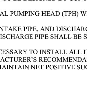
13 Cerro Reservoir Drawdown Plan Cerro Reservoir Outlet Works Replacement Project May 2018 SECTION 4 - DRAWDOWN BY PUMP 4.1 General Reservoir drawdown by pump consists of using a centrifugal pump to move water over and downstream of the dam. The selected pump will need to operate continuously (24 hours a day). 4.2 System Components We expect that the siphon pipe will be used as the discharge pipe to convey water over the dam and into the canal. As the reservoir is lowered the pump may need to be relocated toward the water surface to avoid causing cavitation in the pumping equipment. The pump will likely operate at the following head and discharge rates: 7.5 cfs, 3,400 gpm, 24.5 foot static head, 75 feet of total pumping head (TPH) 4 cfs, 1,800 gpm, 40.5 foot static head, 55 feet of TPH Pumping may need to be initiated near the bottom operational limits of the siphon to supplement discharge capacity and maintain the tentative release schedule presented in Section Cerro Reservoir Drawdown Plan
14 Cerro Reservoir Drawdown Plan Cerro Reservoir Outlet Works Replacement Project May 2018 SECTION 5 - EMBANKMENT MONITORING DURING DRAWDOWN 5.1 Rapid Drawdown Failure Mode Lowering the reservoir level has the potential to cause a rapid drawdown upstream slope failure in the embankment dams. This failure mode develops when the stabilizing buttress of reservoir water is removed faster than water can drain out of the embankment fill. Embankment fill at this Site is particularly susceptible to this failure mode because of the lack of granular free draining material and relatively high plasticity (relatively high plasticity material will tend to retain water longer than lower plasticity material). A rapid drawdown failure would manifest as a displaced wedge or block and would generally resemble a landslide. If the landslide is large enough it could potentially capture the dam crest and create an uncontrolled release of the reservoir potentially causing substantial damage to property and loss of life. Within the reservoir basin a rapid drawdown failure could cause a large block or wedge of upstream slope embankment to rotate into the reservoir basin. To mitigate this potential failure mode we have set limitations on the drawdown rate (vertical feet per day) and have required hold periods to evaluate embankment drainage and allow excess porewater additional time to partially drain. 5.2 General Embankment Monitoring Monitoring the upstream slope for a rapid drawdown failure consists of methodically and consistently observing the slope and halting the drawdown if a change in conditions is observed. During a day when a release is made the embankment should be monitored once daily. During a day when the reservoir level is held constant the embankment should be monitored at least every other day. Monitoring shall include the following activities: Measure the reservoir water level drop in elevation. Using this change in elevation and the reservoir stage/area/capacity table, estimate the discharge flow rate from the siphon and pumps. Adjust flow rate as necessary to hit target drawdown elevations. Embankment Inspection Observe the upstream embankment slope, crest, and downstream slope; take photographs at defined locations and areas of concern; stake areas of potential changing conditions for additional monitoring; and fill out on observation form Cerro Reservoir Drawdown Plan
15 Cerro Reservoir Drawdown Plan Cerro Reservoir Outlet Works Replacement Project May 2018 If there are indications of developing slope instability (cracks, embankment displacement, scarps or slides), stop reservoir drawdown and contact RJH for further evaluation. Monitoring activities are described in the following sections. 5.3 Reservoir Level Monitoring Careful monitoring of the reservoir level is critical for embankment stability as well as maintaining the drawdown schedule. To measure the elevation change in the reservoir we recommend staking a temporary control point near the edge of the water surface along the left abutment of the western embankment and sighting to this control point with an Engineer s hand level or a self-leveling level during drawdown. At each 3-foot drop additional temporary control points should be installed to track progress of the drawdown and provide redundant control points. The temporary control points should be adequately embedded in the subgrade to prevent displacement or vandalism during drawdown. 5.4 Embankment Inspection Embankment inspection consists of walking the length of each embankment (total of three embankments) and sighting the slopes and crest from various angles to detect development of a rapid drawdown slope instability. We have the following recommendations regarding routine inspections of an embankment dam: Maintain Consistent Personnel Personnel responsible for inspection should be consistent throughout the drawdown to maintain continuity and increase their ability to identify changing conditions. Inspection Direction Reverse the direction of the inspection every other day because some features may be more apparent from a different angle. Inspection Time Maintain a consistent inspection time to provide a consistent comparison between photographs. Inspection Photographs Take photographs of areas where potentially changing conditions are occurring and at consistent locations along each embankment slope and crest. Consistent photographs can be used to identify changing conditions. Inspection Forms A Site-specific inspection form has been created for this drawdown and is provided in Appendix B. A plan of the dams to assist in spatially locating concerning features is provided as Figure B.1 in Appendix B Cerro Reservoir Drawdown Plan
16 Cerro Reservoir Drawdown Plan Cerro Reservoir Outlet Works Replacement Project May 2018 Inspection Equipment Engineer s hand level, tape measure, hiking staff, camera, adequate supply of lath and flagging, felt-tipped marker, cellular phone, Emergency Action Plan (EAP), this Plan, and safety equipment. A rapid drawdown failure will likely display the following characteristics prior to and following movement of a large wedge or block: Concentrated Seepage This feature will consist of water flowing out of a single location or a series of locations in the upstream slope riprap or earthen slope above the reservoir water surface. Shallow Depression or Bulge in the Slope This feature can be identified as a subtle change from a continuous slope and could indicate the initiation of a rotational slope failure. To identify a depression or bulge sight along the slope to observe for slight changes in slope grade (slope angle). Cracking This feature generally consists of unexplained separation between two materials or within a single material. A crack is an initial sign of a mass movement and could be present along the upstream slope, crest, or even the downstream slope if the displaced wedge is large enough. Mass Movement, Scarp, and Debris Pile This feature consists of a slope failure where the scarp is a distinct near-vertical step along the upslope edge and the debris pile is the mass of material which has slid off the slope toward the toe of the slope. If any of these conditions are observed, except consistent concentrated seepage, perform the following: Stake the vertical and horizontal limits of the observed feature. Measure pertinent dimensions including the width, length, approximate elevation, and height of the scarp, bulge, and crack width (if applicable). Take lots of photographs. Observe the feature closely and document seepage, cracking, or soft material. Contact RJH immediately for further evaluation and to determine necessary remedial measures. 5.5 Reporting At the conclusion of each day send an electronic copy of reports and photographs to RJH for review Cerro Reservoir Drawdown Plan
17 Cerro Reservoir Drawdown Plan Cerro Reservoir Outlet Works Replacement Project May 2018 SECTION 6 - CONTINGENCY PLAN Below is a list of potential issues that could occur during the drawdown and the suggested mitigation plan to respond to the issue. Based on observed conditions, more aggressive actions may be required than those listed below. Potential Issue: Concentrated seepage observed Description: Water is observed flowing out of a single location or a series of locations in the riprap or earthen slope into the reservoir. Actions: If concentrated seep is within 1 vertical foot of the water surface continue to monitor. If concentrated seep is greater than 1 vertical foot of the water surface stop the reservoir release and hold the water level constant until the concentrated seep dissipates. Notifications: RJH. Potential Issue: Shallow depression or bulge is observed Description: A shallow depression or bulge is observed along a reach of embankment where the slope was previously consistent. Actions: Continue to draw down and monitor the feature. If the feature progresses halt the reservoir drawdown and monitor. Notifications: RJH. Potential Issue: Mass movement, scarp, or debris pile Description: A mass movement is observed along a reach of embankment where the slope was previously consistent. Actions: Stop the reservoir drawdown. Notifications: RJH Cerro Reservoir Drawdown Plan
18 Cerro Reservoir Drawdown Plan Cerro Reservoir Outlet Works Replacement Project May 2018 SECTION 7 - REFERENCES Colorado Office of the State Engineer (SEO, 2017). Engineer s 2017 Inspection Report. Cerro Dam, Dam ID (620105). Construction File Number C-644 (C-644, 1953). Enlargement Plans for Cerro Reservoir Dam. Construction File Number C-644A (C-644A, 1966). Cerro Reservoir Enlargement. Del-Mont Construction Surveyors (Del-Mont, 2017). Existing Site Survey for Cerro Reservoir, Montrose County, CO. Job No Dickinson, Robert G. (Dickinson, 1963). U.S. Geological Survey (USGS), Geologic Map of the Cerro Summit Quandrangle, Montrose County, Colorado. GQ-486 Steven, T.A. and Hail, W.J. Jr. (Steven and Hail, 1989). U.S. Geological Survey (USGS), Geologic Map of the Montrose 30 x60 Quadrangle, Southwestern Colorado. MAP I Cerro Reservoir Drawdown Plan
19 APPENDIX A TENTATIVE SCHEDULE AND DISCHARGE RATES
20 6/1/2018 Start Date 0.5 Release Rate (ft/day) 7980 Low Elevation (feet) 1 Low Elevation Release Rate (ft/day) Tentative Release Schedule Day Date Week Day Target Elevation Drop Water Surface Elevation Storage (acrefeet) Released Volume (acreft) Release Rate (cfs) (24 hours per day) 0 6/1/2018 Monday /2/2018 Tuesday /3/2018 Wednesday /4/2018 Thursday /5/2018 Friday /6/2018 Saturday /7/2018 Sunday /8/2018 Monday /9/2018 Tuesday /10/2018 Wednesday /11/2018 Thursday /12/2018 Friday /13/2018 Saturday /14/2018 Sunday /15/2018 Monday /16/2018 Tuesday /17/2018 Wednesday /18/2018 Thursday /19/2018 Friday /20/2018 Saturday /21/2018 Sunday /22/2018 Monday /23/2018 Tuesday /24/2018 Wednesday /25/2018 Thursday /26/2018 Friday /27/2018 Saturday /28/2018 Sunday /29/2018 Monday /30/2018 Tuesday /1/2018 Wednesday /2/2018 Thursday /3/2018 Friday /4/2018 Saturday /5/2018 Sunday /6/2018 Monday /7/2018 Tuesday /8/2018 Wednesday /9/2018 Thursday /10/2018 Friday /11/2018 Saturday /12/2018 Sunday /13/2018 Monday /14/2018 Tuesday /15/2018 Wednesday /16/2018 Thursday /17/2018 Friday /18/2018 Saturday /19/2018 Sunday /20/2018 Monday /21/2018 Tuesday /22/2018 Wednesday /23/2018 Thursday Approx elevation to start pumping. P:\ Cerro Outlet Works Replacement\Engineering\Task Reservoir Drain Plan\Drain Plan\Attachment A - Release Schedule.xlsx Sheet1 1/2
21 6/1/2018 Start Date 0.5 Release Rate (ft/day) 7980 Low Elevation (feet) 1 Low Elevation Release Rate (ft/day) Tentative Release Schedule Day Date Week Day Target Elevation Drop Water Surface Elevation Storage (acrefeet) Released Volume (acreft) Release Rate (cfs) (24 hours per day) 53 7/24/2018 Friday /25/2018 Saturday /26/2018 Sunday /27/2018 Monday /28/2018 Tuesday /29/2018 Wednesday /30/2018 Thursday /31/2018 Friday /1/2018 Saturday /2/2018 Sunday /3/2018 Monday /4/2018 Tuesday /5/2018 Wednesday /6/2018 Thursday /7/2018 Friday /8/2018 Saturday /9/2018 Sunday /10/2018 Monday /11/2018 Tuesday /12/2018 Wednesday /13/2018 Thursday /14/2018 Friday /15/2018 Saturday /16/2018 Sunday /17/2018 Monday /18/2018 Tuesday /19/2018 Wednesday /20/2018 Thursday /21/2018 Friday /22/2018 Saturday /23/2018 Sunday /24/2018 Monday P:\ Cerro Outlet Works Replacement\Engineering\Task Reservoir Drain Plan\Drain Plan\Attachment A - Release Schedule.xlsx Sheet1 2/2
22 APPENDIX B INSPECTION FORMS

23 Date and Time: Inspector: Weather: Reservoir Elevation (1) Hold Period Yes No CERRO RESERVOIR DRAWDOWN MONITORING REPORT Observation Steps 1. Fill out paperwork for every inspection, whether or not concerning features are observed. 2. If concerning features are observed perform the following: a. Stake vertical and horizontal limits. b. Measure pertinent dimensions (refer to table below). c. Observe feature closely and document seepage, cracking, and soft material. d. Take photographs of the entire feature and close-ups of unique features. Include scale (tape measure, etc.) in photograph, as appropriate. e. Contact RJH (Mike Graber ), as appropriate, (303) (RJH Office). Feature Number (2) Existing Feature (3) Feature (4) Starting Station (5) Length (5) (ft) Elevation (5) (ft) Offset (5)(6) (ft) Notes (7) Western Embankment Southern Embankment Eastern Embankment 1. Water Surface Vertical Distance Below Spillway Flowline: 2. Example W-001 for the first observation at the western embankment. 3. Mark X if the observation was observed on a previous day. 4. Example: Concentrated Seepage (Conc Seep), Depression (Dep) or Bulge, Cracking (crack), Mass Movement (slide) 5. Dimensions are approximate. 6. Width of crack or height of scarp at location of mass movement. 7. If feature has not changed for six days, consider closing out observation point


24
25 APPENDIX C SIPHON DESIGN DRAWINGS


26
27


28
29
30
31


32 SEE BID PACKET FOR DETAIL REGARDING MATERIALS AND WORK PERFORMED BY OTHERS
33 APPENDIX D EXISTING CONSTRUCTION INFORMATION
34
35
36
37
CCR Rule Annual Inspection Report (cont.) 2
 2") The inspection findings consisted of maintenance items and items that were not observed to be signs or potential signs of significant structural weakness. No deficiencies or disrupting conditions that
The inspection findings consisted of maintenance items and items that were not observed to be signs or potential signs of significant structural weakness. No deficiencies or disrupting conditions that
design, construction, operation, and maintenance of the BAP is consistent with recognized and generally accepted good engineering standards.
 design, construction, operation, and maintenance of the BAP is consistent with recognized and generally accepted good engineering standards. In addition to the field inspection, Associated Engineers, Inc.
STRUCTURAL STABILITY ASSESSMENT
 STRUCTURAL STABILITY ASSESSMENT CFR 257.73(d) Bottom Ash Pond Complex Cardinal Plant Brilliant, Ohio October, 2016 Prepared for: Cardinal Operating Company Cardinal Plant Brilliant, Ohio Prepared by: Geotechnical
HISTORY OF CONSTRUCTION FOR EXISTING CCR SURFACE IMPOUNDMENT PLANT GASTON ASH POND 40 CFR (c)(1)(i) (xii)
(1)(i) (xii)") HISTORY OF CONSTRUCTION FOR EXISTING CCR SURFACE IMPOUNDMENT PLANT GASTON ASH POND 40 CFR 257.73(c)(1)(i) (xii) (i) Site Name and Ownership Information: Site Name: E.C. Gaston Steam Plant Site Location:
HISTORY OF CONSTRUCTION FOR EXISTING CCR SURFACE IMPOUNDMENT PLANT GASTON ASH POND 40 CFR 257.73(c)(1)(i) (xii) (i) Site Name and Ownership Information: Site Name: E.C. Gaston Steam Plant Site Location:
RESERVOIR DRAWDOWN RATES/RESERVOIR DRAWDOWN TEST Iron Gate, Copco (I & II), and JC Boyle Dams
, and JC Boyle Dams") TECHNICAL MEMORANDUM No. 1 TO: Michael Bowen California Coastal Conservancy Geotechnical & Earthquake Engineering Consultants CC: Eric Ginney Philip Williams & Associates PREPARED BY: Paul Grant SUBJECT:
TECHNICAL MEMORANDUM No. 1 TO: Michael Bowen California Coastal Conservancy Geotechnical & Earthquake Engineering Consultants CC: Eric Ginney Philip Williams & Associates PREPARED BY: Paul Grant SUBJECT:
Sediment Trap. A temporary runoff containment area, which promotes sedimentation prior to discharge of the runoff through a stabilized spillway.
 Sediment Trap SC-15 Source: Caltrans Construction Site Best Management Practices Manual, 2003. Description A temporary runoff containment area, which promotes sedimentation prior to discharge of the runoff
Stone Outlet Sediment Trap
 3.12 Sediment Control Description: A stone outlet sediment trap is a small detention area formed by placing a stone embankment with an integral stone filter outlet across a drainage swale for the purpose
INFLOW DESIGN FLOOD CONTROL SYSTEM PLAN 40 C.F.R. PART PLANT YATES ASH POND 2 (AP-2) GEORGIA POWER COMPANY
 GEORGIA POWER COMPANY") INFLOW DESIGN FLOOD CONTROL SYSTEM PLAN 40 C.F.R. PART 257.82 PLANT YATES ASH POND 2 (AP-2) GEORGIA POWER COMPANY EPA s Disposal of Coal Combustion Residuals from Electric Utilities Final Rule (40 C.F.R.
INFLOW DESIGN FLOOD CONTROL SYSTEM PLAN 40 C.F.R. PART 257.82 PLANT YATES ASH POND 2 (AP-2) GEORGIA POWER COMPANY EPA s Disposal of Coal Combustion Residuals from Electric Utilities Final Rule (40 C.F.R.
SLOPE STABILITY EVALUATION AND ACCEPTANCE STANDARDS
 INFORMATION BULLETIN / PUBLIC - BUILDING CODE REFERENCE NO.: LABC 7006.3, 7014.1 Effective: 01-01-2017 DOCUMENT NO.: P/BC 2017-049 Revised: 12-21-2016 Previously Issued As: P/BC 2014-049 SLOPE STABILITY
SLOPE STABILITY EVALUATION AND ACCEPTANCE STANDARDS
 INFORMATION BULLETIN / PUBLIC - BUILDING CODE REFERENCE NO.: LAMC 98.0508 Effective: 1-26-84 DOCUMENT NO. P/BC 2002-049 Revised: 11-1-02 Previously Issued As: RGA #1-84 SLOPE STABILITY EVALUATION AND ACCEPTANCE
Geosynthetics Applications and Performance Reviews Select Case Histories
 Geosynthetics Applications and Performance Reviews Select Case Histories Debora J. Miller, Ph.D., P.E.; Dean B. Durkee,, Ph.D., P.E.; Michael A. Morrison, P.E., David B. Wilson, P.E., and Kevin Smith,
Slope Stability Evaluation Ground Anchor Construction Area White Point Landslide San Pedro District Los Angeles, California.
 Slope Stability Evaluation Ground Anchor Construction Area White Point Landslide San Pedro District Los Angeles, California Submitted To: Mr. Gene Edwards City of Los Angeles Department of Public Works
APPENDIX B DESIGN CRITERIA FOR TEMPORARY WATER QUALITY BMPS USED DURING CONSTRUCTION
 APPENDIX B DESIGN CRITERIA FOR TEMPORARY WATER QUALITY BMPS USED DURING CONSTRUCTION This Appendix presents design criteria and example calculations for the following temporary water quality BMPs for use
[1] Performance of the sediment trap depends on the type of outlet structure and the settling pond surface area.
![[1] Performance of the sediment trap depends on the type of outlet structure and the settling pond surface area.](/thumbs/76/74245181.jpg "[1] Performance of the sediment trap depends on the type of outlet structure and the settling pond surface area.") Sediment Trench SEDIMENT CONTROL TECHNIQUE Type 1 System Sheet Flow Sandy Soils Type 2 System [1] Concentrated Flow Clayey Soils Type 3 System [1] Supplementary Trap Dispersive Soils [1] Performance of
Sediment Trench SEDIMENT CONTROL TECHNIQUE Type 1 System Sheet Flow Sandy Soils Type 2 System [1] Concentrated Flow Clayey Soils Type 3 System [1] Supplementary Trap Dispersive Soils [1] Performance of
Project (Project No. US-CA-62-2) Maintenance Inspection and Reports (Subtask 14.1) Inspection Report No.2
 Maintenance Inspection and Reports (Subtask 14.1) Inspection Report No.2") MEMORANDUM TO: FROM: Jim Well, Ducks Unlimited Mike Harvey, PhD, PG SUBJECT: M&T/ Llano Seco Fish Screen Project (Project No. US-CA-62-2) Maintenance Inspection and Reports (Subtask 14.1) Inspection Report
MEMORANDUM TO: FROM: Jim Well, Ducks Unlimited Mike Harvey, PhD, PG SUBJECT: M&T/ Llano Seco Fish Screen Project (Project No. US-CA-62-2) Maintenance Inspection and Reports (Subtask 14.1) Inspection Report
Standards for Soil Erosion and Sediment Control in New Jersey May 2012
 STANDARD FOR SEDIMENT BASIN Definition A barrier, dam, excavated pit, or dugout constructed across a waterway or at other suitable locations to intercept and retain sediment. Basins created by construction
Preliminary Geotechnical Evaluation Gooseberry Point Pedestrian Improvements Whatcom County, Washington SITE AND PROJECT DESCRIPTION
 File No. 12-100 Geotechnical & Earthquake Engineering Consultants Mr. Kevin Brown, P.E. Gray & Osborne, Inc. 3710 168 th Street NE, Suite B210 Arlington, Washington 98223 Subject: Draft Report Preliminary
Sediment Trap. At multiple locations within the project site where sediment control is needed.
 Sediment Trap SE-3 Objectives EC Erosion Control SE Sediment Control TR Tracking Control WE Wind Erosion Control Non-Stormwater NS Management Control Waste Management and WM Materials Pollution Control
Mr. Michael Malone CPS Energy 145 Navarro Street San Antonio, Texas Project No
 January 17, 2018 Mr. Michael Malone 145 Navarro Street San Antonio, Texas 78205 Project No. 0337367 Environmental Resources Management CityCentre Four 840 West Sam Houston Pkwy N. Suite 600 Houston, Texas
Materials. Use materials meeting the following.
 208.01 Section 208. SOIL EROSION AND SEDIMENTATION CONTROL 208.01 Description. Install and maintain erosion and sedimentation controls to minimize soil erosion and to control sedimentation from affecting
This report was prepared by Klohn Crippen Consultants Ltd. for Alberta Transportation Central Region under Contract No. CE053/2000.
 Alberta Transportation Central Region #401, 4902 51 Street Red Deer, Alberta T4N 6K8 June 7, 2002 Mr. Melvin Mayfield, P.Eng. Project Engineer Dear Mr. Mayfield: Central Region Landslide Assessment Site
CHAPTER GEOLOGICALLY HAZARDOUS AREAS Applicability Regulations.
 CHAPTER 19.07 GEOLOGICALLY HAZARDOUS AREAS 19.07.010 Applicability. Geologically hazardous areas may pose a threat to the health and safety of citizens when incompatible development is sited in areas of
Converse Consultants Geotechnical Engineering, Environmental & Groundwater Science, Inspection & Testing Services
 Converse Consultants Geotechnical Engineering, Environmental & Groundwater Science, Inspection & Testing Services Ms. Rebecca Mitchell Mt. San Antonio College Facilities Planning & Management 1100 North
Pierce County Department of Planning and Land Services Development Engineering Section
 Page 1 of 7 Pierce County Department of Planning and Land Services Development Engineering Section PROJECT NAME: DATE: APPLICATION NO.: PCDE NO.: LANDSLIDE HAZARD AREA (LHA) GEOLOGICAL ASSESSMENT REPORT
Emergency Action Plan (EAP) Tata Pond Dam
 Tata Pond Dam") For Official Use Only Not for Public Distribution 02/03/16 Emergency Action Plan (EAP) Tata Pond Dam State of Connecticut Dam ID: 0000 Town or City, County, Connecticut Name of Dam Owner Dam Hazard Classification
For Official Use Only Not for Public Distribution 02/03/16 Emergency Action Plan (EAP) Tata Pond Dam State of Connecticut Dam ID: 0000 Town or City, County, Connecticut Name of Dam Owner Dam Hazard Classification
Converse Consultants Geotechnical Engineering, Environmental & Groundwater Science, Inspection & Testing Services
 Converse Consultants Geotechnical Engineering, Environmental & Groundwater Science, Inspection & Testing Services July 27, 2017 Ms. Rebecca Mitchell Mt. San Antonio College Facilities Planning & Management
This is a digital document from the collections of the Wyoming Water Resources Data System (WRDS) Library.
 Library.") This is a digital document from the collections of the Wyoming Water Resources Data System (WRDS) Library. For additional information about this document and the document conversion process, please contact
This is a digital document from the collections of the Wyoming Water Resources Data System (WRDS) Library. For additional information about this document and the document conversion process, please contact
ENGINEER S CERTIFICATION OF FAULT AREA DEMONSTRATION (40 CFR )
") PLATTE RIVER POWER AUTHORITY RAWHIDE ENERGY STATION BOTTOM ASH TRANSFER (BAT) IMPOUNDMENTS LARIMER COUNTY, CO ENGINEER S CERTIFICATION OF FAULT AREA DEMONSTRATION (40 CFR 257.62) FOR COAL COMBUSTION RESIDUALS
PLATTE RIVER POWER AUTHORITY RAWHIDE ENERGY STATION BOTTOM ASH TRANSFER (BAT) IMPOUNDMENTS LARIMER COUNTY, CO ENGINEER S CERTIFICATION OF FAULT AREA DEMONSTRATION (40 CFR 257.62) FOR COAL COMBUSTION RESIDUALS
June 9, R. D. Cook, P.Eng. Soils Engineer Special Services Western Region PUBLIC WORKS CANADA WESTERN REGION REPORT ON
 PUBLIC WORKS CANADA WESTERN REGION REPORT ON GEOTECHNICAL INVESTIGATION PROPOSED MARTIN RIVER BRIDGE MILE 306.7 MACKENZIE HIGHWAY Submitted by : R. D. Cook, P.Eng. Soils Engineer Special Services Western
Big Rivers Electric Corporation Disposal of Coal Combustion Residuals (CCR) from Electric Utilities Final Rule CCR Impoundment Liner Assessment Report
 from Electric Utilities Final Rule CCR Impoundment Liner Assessment Report") Big Rivers Electric Corporation Disposal of Coal Combustion Residuals (CCR) from Electric Utilities Final Rule CCR Impoundment Liner Assessment Report CCR Surface Impoundment Information Name: Operator:
Big Rivers Electric Corporation Disposal of Coal Combustion Residuals (CCR) from Electric Utilities Final Rule CCR Impoundment Liner Assessment Report CCR Surface Impoundment Information Name: Operator:
Limited Visual Dam Safety Inspections OA Oahu Reservoir No Oahu, Hawaii
 Limited Visual Dam Safety Inspections OA00137 Oahu Reservoir No. 155 Oahu, Hawaii Prepared by: U.S. ARMY CORPS OF ENGINEERS HONOLULU DISTRICT STATE OF HAWAII DEPARTMENT OF LAND AND NATURAL RESOURCES May
3301 East 120 th Avenue Assited Living & Memory Care
 UTILITY REPORT FOR 3301 East 120 th Avenue Assited Living & Memory Care 1 st Submittal January 23, 2016 2 nd Submittal March 04, 2016 Prepared for: 3301 E. 120 th Ave, LLC. 8200 E. Maplewood Ave., Suite
EXHIBIT H LOT 317 GRADING AND SITE PLAN
 EXHIBIT H LOT 317 GRADING AND SITE PLAN EXHIBIT I LOT 317 ELEVATIONS ridge height 4915'-6" GENERAL & KEYED NOTES ridge height 4905'-9" 3 7 4 A5.1 1 5 ridge height 4910'-6" 2 ridge height 4906'-3" 1 Provide
IV. ENVIRONMENTAL IMPACT ANALYSIS G. GEOLOGY AND SOILS
 IV. ENVIRONMENTAL IMPACT ANALYSIS G. GEOLOGY AND SOILS The following section is a summary of the geotechnical report conducted for the proposed project. The Report of Geotechnical Investigation Proposed
THE NEED FOR AN ADDITIONAL SPILLWAY AT THE SANFORD DAM BOILING SPRING LAKES, NC. Presentation for The Brunswick County Commissioners April 20, 2015
 THE NEED FOR AN ADDITIONAL SPILLWAY AT THE SANFORD DAM BOILING SPRING LAKES, NC Presentation for The Brunswick County Commissioners April 20, 2015 The Sanford Dam Earth Dam constructed in 1961 Drainage
Engineer. Engineering. Engineering. (in-ja-neer ) A person trained and skilled in any of the various branches of engineering: a civil engineer
 A person trained and skilled in any of the various branches of engineering: a civil engineer") Engineer (in-ja-neer ) A person trained and skilled in any of the various branches of engineering: a civil engineer (Random House Webster s College Dictionary, 1991) CE100 Introduction to Civil Geotechnical
Engineer (in-ja-neer ) A person trained and skilled in any of the various branches of engineering: a civil engineer (Random House Webster s College Dictionary, 1991) CE100 Introduction to Civil Geotechnical
DAM SAFETY PROGRAM DAM INSPECTION REPORT FORM FOR REGULATORY INSPECTION
 DAM SAFETY PROGRAM DAM INSPECTION REPORT FORM FOR REGULATORY INSPECTION Please complete this form in accordance with the instructions (DEEP-DAM-INST-002). Part I: Summary of Dam Inspection Dam Name: Knofla
Estimated Sediment Volume: Bridge Street Dam Impoundment, Royal River, Yarmouth, Maine
 University of Southern Maine USM Digital Commons Publications Casco Bay Estuary Partnership (CBEP) 2015 Estimated Sediment Volume: Bridge Street Dam Impoundment, Royal River, Yarmouth, Maine Stantec Follow
January 12, 2006 File:
 January 12, 2006 File: 15-85-13 Alberta Infrastructure and Transportation Room 301, Provincial Building 9621-96 Avenue Peace River, Alberta T8S 1T4 Attention: Mr. Ed Szmata PEACE REGION (PEACE HIGH LEVEL
ISSUED FOR CONSTRUCTION
 PAGE No. DESCRIPTION 1 Cover Page 2 Overview Map 3 Western Road Plan View 4 Eastern Road Plan View West Road Profiles & Cross Sections 6-7 East Road Profiles 8- East Road Cross Sections 11-14 Campsite
1.0 INSPECTION ANNUAL INSPECTION, JUNE 29, 2011 CARMACKS COPPER PROJECT, CARMACKS, YUKON. Dear Mr. West-Sells,
 Doc. No. 162 Rev. 0 Mr. Paul West-Sells President & Chief Operating Officer Western Copper Corporation 2060-1111 West Georgia Street Vancouver, BC V6E 4M3 ANNUAL INSPECTION, JUNE 29, 2011 CARMACKS COPPER
The results of KCB s site inspection observations and our recommendations for further work are presented herein.
 July 14, 2015 Central Region 401, 4902 51 Street Red Deer, Alberta T4N 6K8 Mr. Tony Penney, P.Eng. Construction Engineer Dear Mr. Penney: June 25, 2015 Site Inspection Report The above site was visited
Black Gore Creek 2013 Sediment Source Monitoring and TMDL Sediment Budget
 Black Gore Creek 2013 Sediment Source Monitoring and TMDL Sediment Budget Prepared for: Prepared By: - I. Introduction The Black Gore Creek Total Maximum Daily Load (TMDL) was developed in collaboration
January 17, 2008 File:
 January 17, 2008 File: 15-85-73 Alberta Infrastructure and Transportation Room 301, Provincial Building 9621-96 Avenue Peace River, Alberta T8S 1T4 Attention: Mr. Ed Szmata PEACE REGION (SWAN HILLS AREA)
3.12 Geology and Topography Affected Environment
 3 Affected Environment and Environmental Consequences 3.12 Geology and Topography 3.12.1 Affected Environment 3.12.1.1 Earthquakes Sterling Highway MP 45 60 Project Draft SEIS The Kenai Peninsula is predisposed
APPENDIX B WORKSHEETS & EXHIBITS
 APPENDIX B WORKSHEETS & EXHIBITS A worksheet provides the designer a representation of a measure that allows for input of specific design criteria. The plan designer will be required to assess field conditions
Instructor : Dr. Jehad Hamad. Chapter (7)
") Instructor : Dr. Jehad Hamad Chapter (7) 2017-2016 Soil Properties Physical Properties Mechanical Properties Gradation and Structure Compressibility Soil-Water Relationships Shear Strength Bearing Capacity
Instructor : Dr. Jehad Hamad Chapter (7) 2017-2016 Soil Properties Physical Properties Mechanical Properties Gradation and Structure Compressibility Soil-Water Relationships Shear Strength Bearing Capacity
TAKING THE MYSTERY OUT OF USACE S ER DRILLING IN EARTH EMBANKMENT DAMS AND LEVEES
 TAKING THE MYSTERY OUT OF USACE S ER 1110-1-1807 DRILLING IN EARTH EMBANKMENT DAMS AND LEVEES 237 237 237 217 217 217 200 200 200 80 119 27 252 174.59 1 255 255 255 0 0 0 163 163 163 131 132 122 239 65
Geotechnical Investigation Juneau Seawalk - Taku Fisheries to Miner s Wharf Juneau, Alaska DM&A Job No
 Duane Miller & Associates 5821 Arctic Boulevard, Suite A Anchorage, AK 99518-1654 (907) 644-3200 Fax 644-0507 Arctic & Geotechnical Engineering May 4, 2006 Tetra Tech/KCM, Inc. 1971 First Avenue Seattle,
Illinois State Water Survey Division
 Illinois State Water Survey Division SURFACE WATER SECTION SWS Contract Report 413 AT THE UNIVERSITY OF ILLINOIS SEDIMENTATION SURVEY OF DAWSON LAKE, MORAINE VIEW STATE PARK, MC LEAN COUNTY, ILLINOIS by
Rock Fall Study Warm Springs Village Warm Springs Avenue Boise, Idaho
 Rock Fall Study Warm Springs Village Warm Springs Avenue Boise, Idaho Prepared For: Mr. Bill Clark Warm Springs Enterprises, LLC 420 Main Street, Suite 204 Boise, Idaho 83702 Prepared By: STRATA, A Professional
FRIENDS OF THE EEL RIVER
 FRIENDS OF THE EEL RIVER Working for the recovery of our Wild & Scenic River, its fisheries and communities. Frank Blackett, Regional Engineer Office of Energy Projects Division of Dam Safety and Inspections
Suitable Applications Sediment traps should be considered for use:
 Categories EC Erosion Control SE Sediment Control TC Tracking Control WE Wind Erosion Control Non-Stormwater NS Management Control Waste Management and WM Materials Pollution Control Legend: Primary Objective
Seismic Design of a Hydraulic Fill Dam by Nonlinear Time History Method
 Seismic Design of a Hydraulic Fill Dam by Nonlinear Time History Method E. Yıldız & A.F. Gürdil Temelsu International Engineering Services Inc., Ankara, Turkey SUMMARY: Time history analyses conducted
PEACE RIVER EAST HILL - HWY 2:60 (PH2) SELECT PHOTOGRAPHS August 22, 2007 File: Photo E003. Station May 2007
 SELECT PHOTOGRAPHS August 22, 2007 File: Photo E003. Station May 2007") Photo E003 0+000 Viewing looking upslope at Site 4 from highway. Conditions unchanged from 2006. Photo E018 0+000 Localized erosion within road fill on upslope side of highway. Photo E022 0+250 Looking
Photo E003 0+000 Viewing looking upslope at Site 4 from highway. Conditions unchanged from 2006. Photo E018 0+000 Localized erosion within road fill on upslope side of highway. Photo E022 0+250 Looking
APPENDIX G APPENDIX G SEDIMENT CONTAINMENT SYSTEM DESIGN RATIONALE
 APPENDIX G SEDIMENT CONTAINMENT SYSTEM DESIGN RATIONALE March 18, 2003 This page left blank intentionally. March 18, 2003 G-2 FIGURES Page # Figure G.1 Estimated Runoff from Precipitation Over Different
Stage Discharge Tabulation for Only Orifice Flow
 Stage Discharge Tabulation for Only Orifice Flow DEPTH STAGE DISCHARGE (meters) (feet) (meters) (feet) (m 3 /s) (ft 3 /s) 0 0.20 0.40 0.60 0.80 1.00 1.20 1.40 1.60 1.80 2.00 0.7 1.3 2.0 2.6 3.3 3.9 4.6
J. Paul Guyer, P.E., R.A.
 J. Paul Guyer, P.E., R.A. Paul Guyer is a registered mechanical engineer, civil engineer, fire protection engineer and architect with over 35 years experience in the design of buildings and related infrastructure.
U-Shaped Sediment Traps
 U-Shaped Sediment Traps SEDIMENT CONTROL TECHNIQUE Type 1 System Sheet Flow Sandy Soils Type 2 System Concentrated Flow Clayey Soils [1] Type 3 System Supplementary Trap Dispersive Soils [1] Generally
Chapter 7 Mudflow Analysis
 Chapter 7 Mudflow Analysis 7.0 Introduction This chapter provides information on the potential and magnitude of mud floods and mudflows that may develop in Aspen due to rainfall events, snowmelt, or rain
CHAPTER 6, PRELIMINARY SITE INVESTIGATION CONTENTS
 CHAPTER 6, PRELIMINARY SITE INVESTIGATION CONTENTS - Page Purpose... 6-1 Assembly of data... 6-1 Use of aerial photographs... 6-2 Field study... 6-3 Mappix... 6-4 Repcrt of preliminary investigation...
PRELIMINARY DRAFT FOR DISCUSSION PURPOSES
 Memorandum To: David Thompson From: John Haapala CC: Dan McDonald Bob Montgomery Date: February 24, 2003 File #: 1003551 Re: Lake Wenatchee Historic Water Levels, Operation Model, and Flood Operation This
HISTORY OF CONSTRUCTION FOR EXISTING CCR SURFACE IMPOUNDMENT PLANT GADSDEN ASH POND 40 CFR (c)(1)(i)-(xii)
(1)(i)-(xii)") HISTORY OF CONSTRUCTION FOR EXISTING CCR SURFACE IMPOUNDMENT PLANT GADSDEN ASH POND 40 CFR 257.73(c)(1)(i)-(xii) (i) Site Name and Ownership Information: Site Name: Site Location: Site Address: Gadsden
HISTORY OF CONSTRUCTION FOR EXISTING CCR SURFACE IMPOUNDMENT PLANT GADSDEN ASH POND 40 CFR 257.73(c)(1)(i)-(xii) (i) Site Name and Ownership Information: Site Name: Site Location: Site Address: Gadsden
WHITE POINT LANDSLIDE GEOTECHNICAL INVESTIGATION November 29, 2012 Status Report
 Gary Lee Moore, P.E., City Engineer Vince Jones, P.E., Deputy City Engineer WHITE POINT LANDSLIDE GEOTECHNICAL INVESTIGATION November 29, 2012 Status Report White Point Landslide Geotechnical Investigation
STEVENS CREEK DAM SEISMIC STABILITY EVALUATIONS OF CHESBRO, LENIHAN, STEVENS CREEK, AND UVAS DAMS (SSE2) PHASE A: STEVENS CREEK AND LENIHAN DAMS
 PHASE A: STEVENS CREEK AND LENIHAN DAMS") SEISMIC STABILITY EVALUATIONS OF CHESBRO, LENIHAN, STEVENS CREEK, AND UVAS DAMS (SSE2) PHASE A: STEVENS CREEK AND LENIHAN DAMS STEVENS CREEK DAM COMPILATION REPORT (REPORT No. SSE2A-SC) Prepared for SANTA
SEISMIC STABILITY EVALUATIONS OF CHESBRO, LENIHAN, STEVENS CREEK, AND UVAS DAMS (SSE2) PHASE A: STEVENS CREEK AND LENIHAN DAMS STEVENS CREEK DAM COMPILATION REPORT (REPORT No. SSE2A-SC) Prepared for SANTA
1 INTRODUCTION 1.1 General
 #701 475 Howe Street Vancouver, British Columbia V6C 2B3 August 1, 2014 Robin McCall Wolverine Mine Environmental Superintendent Dear Mr. McCall: 1 INTRODUCTION 1.1 General This letter report presents
Horizontal Directional Drilling: An Approach to Design and Construction. Presenter: John Briand, PE Co-Author: Danielle Neamtu, PE
 Horizontal Directional Drilling: An Approach to Design and Construction Presenter: John Briand, PE Co-Author: Danielle Neamtu, PE Presentation Outline General HDD overview Conceptual-level evaluation Detailed
WATER DISTRIBUTION NETWORKS
 WATER DISTRIBUTION NETWORKS CE 370 1 Components of Water Supply System 2 1 Water Distribution System Water distribution systems are designed to adequately satisfy the water requirements for a combinations
MINISTRY OF ENERGY AND MINES Mines and Mineral Resources. REPORT OF GEOTECHNICAL INSPECTOR (Issued pursuant to Section 15 of the Mines Act)
") MINISTRY OF ENERGY AND MINES Mines and Mineral Resources REPORT OF GEOTECHNICAL INSPECTOR (Issued pursuant to Section 15 of the Mines Act) Name of Property: Permit No.: M-203 General Manager: Company:
MINISTRY OF ENERGY AND MINES Mines and Mineral Resources REPORT OF GEOTECHNICAL INSPECTOR (Issued pursuant to Section 15 of the Mines Act) Name of Property: Permit No.: M-203 General Manager: Company:
Summary of Hydraulic and Sediment-transport. Analysis of Residual Sediment: Alternatives for the San Clemente Dam Removal/Retrofit Project,
 Appendix N SUMMARY OF HYDRAULIC AND SEDIMENT-TRANSPORT ANALYSIS OF RESIDUAL SEDIMENT: ALTERNATIVES FOR THE SAN CLEMENTE DAM REMOVAL/RETROFIT PROJECT, CALIFORNIA the San Clemente Dam Removal/Retrofit Project,
PRELIMINARY ENGINEERING REPORT FOR SANITARY SEWER COLLECTION SYSTEM OSKALOOSA, IOWA 2017
 PRELIMINARY ENGINEERING REPORT FOR SANITARY SEWER COLLECTION SYSTEM OSKALOOSA, IOWA 2017 PRELIMINARY ENGINEERING REPORT FOR SANITARY SEWER COLLECTION SYSTEM OSKALOOSA, IOWA 2017 I hereby certify that this
December 11, 2006 File:
 December 11, 2006 File: 15-85-38 Alberta Infrastructure and Transportation Room 301, Provincial Building 9621-96 Avenue Peace River, Alberta T8S 1T4 Attention: Mr. Ed Szmata PEACE REGION (SWAN HILLS AREA)
Redwood City Harbor, California, Navigation Improvement Feasibility Study. Appendix D. Geotechnical Engineering. DRAFT April 2015
 1 Redwood City Harbor, California, Navigation Improvement Feasibility Study Appendix D Geotechnical Engineering DRAFT April 2015 2 Contents 1 Purposes of Report... 3 2 Background... 3 3 References and
Dam Safety Aspects of Reservoir-Triggered Seismicity
 Dam Safety Aspects of Reservoir-Triggered Seismicity Dr. Martin Wieland Chairman, Committee on Seismic Aspects of Dam Design, International Commission on Large Dams (ICOLD) Poyry Energy Ltd., Zurich, Switzerland
Coarse Sediment Traps
 Coarse Sediment Traps SEDIMENT CONTROL TECHNIQUE Type 1 System Sheet Flow Sandy Soils Type 2 System [1] Concentrated Flow Clayey Soils [2] Type 3 System Supplementary Trap Dispersive Soils [1] Though primarily
R.M.HARW & ASSOCIATES LTD. GEOTECHNICAL INVESTIGATION PROPOSED BRIDGE SITE. HELAVA CREEKl MILE MACKENZIE HIGHWAY E-2510 OCTOBER 16, 1973
 El R.M.HARW & ASSOCIATES LTD. GEOTECHNICAL INVESTIGATION PROPOSED BRIDGE SITE HELAVA CREEKl MILE 616.4 MACKENZIE HIGHWAY E-2510 OCTOBER 16, 1973 R,M,HARDV & ASSOCIATES LTD. CONSULTING ENGINEERING & TESTING
Eastlake Assited Living & Memory Care
 UTILITY REPORT FOR Eastlake Assited Living & Memory Care 1 st Submittal January 23, 2016 2 nd Submittal March 04, 2016 June 7, 2016 Final Submittal August 08, 2016 Prepared for: 3301 E. 120 th Ave, LLC.
WHAT SEISMIC HAZARD INFORMATION THE DAM ENGINEERS NEED FROM SEISMOLOGISTS AND GEOLOGISTS?
 WHAT SEISMIC HAZARD INFORMATION THE DAM ENGINEERS NEED FROM SEISMOLOGISTS AND GEOLOGISTS? Martin WIELAND 1 ABSTRACT For large dam projects a site-specific seismic hazard analysis is usually recommended.
Landslide FE Stability Analysis
 Landslide FE Stability Analysis L. Kellezi Dept. of Geotechnical Engineering, GEO-Danish Geotechnical Institute, Denmark S. Allkja Altea & Geostudio 2000, Albania P. B. Hansen Dept. of Geotechnical Engineering,
Sacramento Modesto Roseville Pleasanton September 19, 2013 Marcia Medina GHD Inc. 417 Montgomery Street, Suite 700 San Francisco, CA Subject: GE
 Sacramento Modesto Roseville Pleasanton September 19, 2013 Marcia Medina GHD Inc. 417 Montgomery Street, Suite 700 San Francisco, CA 94104 Subject: GEOTECHNICAL REPORT AMENDMENT Stonybrook Creek Crossings
THE MINISTRY OF ENERGY AND ENERGY INDUSTRIES MINERALS DIVISION MINE DESIGN TEMPLATE OPERATOR NAME: OPERATOR ADDRESS: PHONE NUMBER: FACSIMILE:
 THE MINISTRY OF ENERGY AND ENERGY INDUSTRIES MINERALS DIVISION MINE DESIGN TEMPLATE 1.0 GENERAL INFORMATION OPERATOR NAME: OPERATOR ADDRESS: PHONE NUMBER: FACSIMILE: NAME OF CONTACT: CELLULAR PHONE: EMAIL
Drivable Grass Report for Hydraulic Performance Testing
 Drivable Grass Report for Hydraulic Performance Testing Prepared for Soil Retention Products, Inc. Prepared by Michael D. Turner Amanda L. Cox Christopher I. Thornton March 2011 Colorado State University
9/13/2011 CHAPTER 9 AND SUBSIDENCE. Case History: La Conchita Landslide. Introduction
 CHAPTER 9 SLOPE PROCESSES, LANDSLIDES, AND SUBSIDENCE Case History: La Conchita Landslide La Conchita: small coastal community 80 km (50 mi) northwest of Los Angeles Landslide occurred on January 10, 2005
Rock & Aggregate Drop Inlet Protection
 Rock & Aggregate Drop Inlet Protection SEDIMENT CONTROL TECHNIQUE Type 1 System Sheet Flow Sandy Soils Type 2 System [1] Concentrated Flow Clayey Soils Type 3 System Supplementary Trap Dispersive Soils
DRAFT. PRELIMINARY LANDSLIDE MODELING for KRAMER AVENUE LANDSLIDE SITKA, ALASKA. Prepared for: Andrew Friske 210 Kramer Ave. Sitka, Alaska 99835
 PRELIMINARY LANDSLIDE MODELING for KRAMER AVENUE LANDSLIDE SITKA, ALASKA Prepared for: Andrew Friske 210 Kramer Ave. Sitka, Alaska 99835 Prepared by: Northern Geotechnical Engineering, Inc. d.b.a. Terra
CHRACTERISTICS OF LANDSLIDE OCCURRED IN LOPARE, BOSNIA AND HERZEGOVINA
 CHRACTERISTICS OF LANDSLIDE OCCURRED IN LOPARE, BOSNIA AND HERZEGOVINA Jun Sugawara 1 and Takao Aizawa 2 1 WorleyParsons, Australia 2 Suncoh Consultants, Japan ABSTRACT This paper presents results of detailed
Table 5-1 Sampling Program Summary for Milltown Ford Avenue Redevelopment Area, NJ.
 Table 5- Sampling Program Summary for Milltown Ford Avenue Redevelopment Area, NJ. Transformer Pads (9 pads: PAD 9) Evaluate if PCBs presently exist in soils adjacent to, and/or beneath the transformer
Appendix E Guidance for Shallow Flooding Analyses and Mapping
 Appendix E Guidance for Shallow Flooding Analyses and Mapping E.1 Introduction Different types of shallow flooding commonly occur throughout the United States. Types of flows that result in shallow flooding
Section 4: Model Development and Application
 Section 4: Model Development and Application The hydrologic model for the Wissahickon Act 167 study was built using GIS layers of land use, hydrologic soil groups, terrain and orthophotography. Within
APPROACH FILL DESIGN OF NORTH SASKATCHEWAN RIVER BRIDGE. A.F. Ruban, EBA Engineering Consultants Ltd., Edmonton, Alberta, Canada
 APPROACH FILL DESIGN OF NORTH SASKATCHEWAN RIVER BRIDGE A.F. Ruban, EBA Engineering Consultants Ltd., Edmonton, Alberta, Canada Paper prepared for presentation at the Slope and Embankment Engineering for
Monitoring and Characterization of the Meadowview Lane Landslide: Boyd County, KY
 Monitoring and Characterization of the Meadowview Lane Landslide: Boyd County, KY Matt Crawford Appalachian Coalition for Geologic Hazards in Transportation 13 th Annual Technical Forum Harrisonburg, VA
CEMEX Eliot Quarry. Lake A Evaluation Report. Alameda County, California
 May 7, 2015 May 7, 2015 Project No. GT13-16 Prepared for: CEMEX 5180 Golden Foothills, Parkway El Dorado Hills, California 95762 7400 Shoreline Drive, Ste. 6 Stockton, California 95219 Tel: 209-472-1822
ROCK EXCAVATION (GRADING) OPSS 206 INDEX
 OPSS 206 INDEX") 206-2 - OPSS 206 INDEX 206-2.1 GENERAL 206-2.1.1 Classification of Rock Materials 206-2.1.2 Tender Items 206-2.1.3 Other Excavation Tender Items 206-2.1.4 Specifications 206-2.1.5 Special Provisions 206-2.1.6
206-2 - OPSS 206 INDEX 206-2.1 GENERAL 206-2.1.1 Classification of Rock Materials 206-2.1.2 Tender Items 206-2.1.3 Other Excavation Tender Items 206-2.1.4 Specifications 206-2.1.5 Special Provisions 206-2.1.6
FOR PROJECTS INITIATED AFTER NOVEMBER 1, 2008 ITEM 716 EMBANKMENT EARTH OUTLET SEDIMENT TRAP
 AFTER NOVEMBER 1, 2008 ITEM 716 EMBANKMENT EARTH OUTLET SEDIMENT TRAP 716.1 Description. This work shall consist of furnishing, installing, maintaining, and removing temporary erosion protection and sediment
PERENNIAL PROBLEM OF EARTHEN BUND OF WELLINGDON RESERVOIR. ANALYSIS OF CAUSES AND REMEDIAL MEASURES A CASE STUDY.
 PERENNIAL PROBLEM OF EARTHEN BUND OF WELLINGDON RESERVOIR. ANALYSIS OF CAUSES AND REMEDIAL MEASURES A CASE STUDY. By Er. S. Muthu Parvatha Vardhini, Asst. Executive Engineer, (Designs) Water Resources
Impact : Changes to Existing Topography (Less than Significant)
") 4.2 Land Resources 4.2.1 Alternative A Proposed Action Impact 4.2.1-1: Changes to Existing Topography (Less than Significant) Development of the project site would involve grading and other earthwork as
4.2 Land Resources 4.2.1 Alternative A Proposed Action Impact 4.2.1-1: Changes to Existing Topography (Less than Significant) Development of the project site would involve grading and other earthwork as
Sediment Control Practices. John Mathews Ohio Dept. of Natural Resources, Division of Soil and Water Resources
 Sediment Control Practices John Mathews Ohio Dept. of Natural Resources, Division of Soil and Water Resources Practices Treat the Largest Soil Particles Sand Sand Silt Clay Treated Untreated Settleable
3.18 GEOLOGY AND SOILS
 3.18 GEOLOGY AND SOILS This section discusses geologic resource concerns as they relate to the environment, public safety, and project design both during construction and after completion of the project.
Lab 12: Mass Wasting
 Name: Lab 12: Mass Wasting Part I. An Earthflow Use the Lake San Cristobal Quadrangle for the following: 1. What is the elevation of Lake San Cristobal? Is the edge of the lake, where the water touches
Pressure Head: Pressure head is the height of a column of water that would exert a unit pressure equal to the pressure of the water.
 Design Manual Chapter - Stormwater D - Storm Sewer Design D- Storm Sewer Sizing A. Introduction The purpose of this section is to outline the basic hydraulic principles in order to determine the storm