FOUNDATION REPORT US 50/LATROBE ROAD WEST BOUND OFF-RAMP UC (BRIDGE NO K) 03-ED-50, EA 03-2E5101 EL DORADO COUNTY, CALIFORNIA
|
|
|
- Marvin Paul
- 5 years ago
- Views:
Transcription
1 FOUNDATION REPORT US 50/LATROBE ROAD WEST BOUND OFF-RAMP UC (BRIDGE NO K) 03-ED-50, EA 03-2E5101 EL DORADO COUNTY, CALIFORNIA Prepared by: BLACKBURN CONSULTING Blocker Drive, Suite 110 Auburn, CA (530) March 2012 Prepared For: Quincy Engineering, Inc. Sacramento, California
2
3 FOUNDATION REPORT US 50 / Latrobe Road West Bound Off-Ramp UC P.M. 0.9, Bridge No K, 03-ED-50, EA 03-2E5101 El Dorado County, California TABLE OF CONTENTS 1 INTRODUCTION Purpose Scope of Services Site Description Project Description DOCUMENT REVIEW Caltrans Consultant Reports SUBSURFACE INVESTIGATION LABORATORY TESTS SITE GEOLOGY AND SUBSURFACE CONDITIONS Regional Geology Local Geology and Faulting Subsurface Soil and Rock Conditions Caltrans Previous Consultant Explorations BCI Exploration Groundwater Caltrans Previous Consultant Explorations BCI Observations CORROSION EVALUATION Previous Studies Current Study NATURALLY OCCURRING ASBESTOS SEISMIC DATA AND EVALUATION Geologic Hazards Seismic Study Ground Motion Study Liquefaction Evaluation Fault Rupture Seismic Settlement Seismic Slope Instability AS-BUILT FOUNDATION DATA...12
4 FOUNDATION REPORT US 50 / Latrobe Road West Bound Off-Ramp UC P.M. 0.9, Bridge No K, 03-ED-50, EA 03-2E5101 El Dorado County, California TABLE OF CONTENTS (continued) 10 FOUNDATION RECOMMENDATIONS Spread Footing Data Table Settlement Lateral Load Resistance Retaining Walls Approach Fill Earthwork Fill Material Expansive Material Geometry and Stability Site Preparation Settlement LATERAL EARTH PRESSURES CONSTRUCTION CONSIDERATIONS Excavation and Shoring Foundation Construction Foundation Monitoring Dewatering Naturally Occurring Asbestos Storm Water Quality RISK MANAGEMENT LIMITATIONS...21
5 FOUNDATION REPORT US 50 / Latrobe Road West Bound Off-Ramp UC P.M. 0.9, Bridge No K, 03-ED-50, EA 03-2E5101 El Dorado County, California TABLE OF CONTENTS (continued) FIGURES Figure 1 Figure 2 Figure 3 Figure 4 Vicinity Map Geologic Map Seismic Hazard Map ARS Curve APPENDIX A Subsurface Exploration Summary Laboratory Test Results Log of Test Borings o Latrobe Road WB Off-Ramp Undercrossing o Latrobe Road Undercrossing (BCI, August 2007) General Plan Foundation Plan APPENDIX B Footing Data (provided by QEI) Calculations for WSD Design and LRFD Design APPENDIX C Caltrans Review Comment and BCI Response
6 FOUNDATION REPORT BCI Job. No US 50 / Latrobe Road West Bound Off-Ramp Undercrossing March 30, 2012 P.M. 0.9, Bridge No K, 03-ED-50, EA 03-2E5101 El Dorado County, California 1 INTRODUCTION 1.1 Purpose Blackburn Consulting (BCI) prepared this Foundation Report for the proposed Latrobe Road West Bound Off-Ramp Undercrossing (UC, Bridge No K) in El Dorado County, California. BCI prepared this report in accordance with our Agreement dated February 3, 2012 between BCI and Quincy Engineering, Inc. (QEI). BCI prepared this report for QEI and the design team to use for project design. Do not use or rely upon this report for different locations or improvements without the written consent of BCI. 1.2 Scope of Services To prepare this report, BCI: Discussed the project with the QEI design team Reviewed available project documentation provided by QEI and obtained by BCI Reviewed published maps and literature related to site soil, rock, and geologic conditions Drilled/excavated, logged, and sampled one boring and one trench to supplement existing subsurface data at the UC location Performed engineering analysis 1.3 Site Description The project is located on US 50 about 4,500 feet east of the Sacramento County line in El Dorado County, California where US 50 crosses over Latrobe Road. Latrobe Road changes to El Dorado Hills Boulevard immediately north of US 50. The project is part of the US 50 Phase-1 HOV Lane Project that extends from the Sacramento/El Dorado County line (PM 0.0) to west of Bass Lake Road (PM 2.9) along US 50. Figure 1 shows the bridge site location. 1.4 Project Description The proposed project is approximately the 4th construction phase (and final bridge construction phase) of the ultimate improvement project for this interchange. Funding for the project is State and Local. The overall project consists of reconstruction of the westbound on- and off-ramps of the El Dorado Hills Boulevard/Latrobe Road interchange on US 50 from Post Mile (PM) 0.20 to Proposed improvements include: -1-
7 FOUNDATION REPORT BCI Job. No US 50 / Latrobe Road West Bound Off-Ramp Undercrossing March 30, 2012 P.M. 0.9, Bridge No K, 03-ED-50, EA 03-2E5101 El Dorado County, California West bound diagonal on-ramp West bound loop off-ramp Latrobe Road West Bound Off-Ramp UC (Bridge No K) Installation of new signals at the westbound ramp intersection Modifications to the existing intersection at El Dorado Hills Boulevard and Saratoga Way Overhead sign structure at the off-ramp exit Drainage system improvements Removal of the existing west bound ramps and signalized intersection The UC bridge will consist of a two-span precast, prestressed, concrete box girder structure and will be 200 feet long and approximately 39 feet wide. The new deck grade will pass through elevation at Abutment-1 (west end) and at Abutment-3 (east end). The substructure will consist of high wall abutments and a two-column bent, all supported on spread footings in rock. Based on discussions with QEI, uniform base of spread footing foundations are planned at elevation feet for all supports. New retaining walls will include Standard Type 1 walls on the north side of the bridge with infill walls on the south side (between the new bridge and the existing). The infill wall will have a height similar to the abutment walls (approximately 24 to 30 feet). The retaining walls on the north side will vary in height from 16 to 24 feet with foundations stepping up from elevation 602 feet to 610 feet. See the General Plan and Foundation Plan attached in Appendix A for bridge details. Benchmark datum used for this project is National Geodetic Vertical Datum of 1929 and North American Datum of DOCUMENT REVIEW To determine subsurface conditions and develop foundation design and construction recommendations, BCI reviewed the following structure/site information published by the State of California Bridge Department (Caltrans) and private consultant reports. 2.1 Caltrans Foundation Study, Latrobe Road UC, III-EC-11-A, Bridge No R/L, OR, March 15, As-Built Plans, Latrobe Road Undercrossing, Sheets 1/11 11/11, As-Built stamp undated, plans dated January 6, Memorandum, Foundation Report for Latrobe Road UC (Br R/L & OR), August 3,
8 FOUNDATION REPORT BCI Job. No US 50 / Latrobe Road West Bound Off-Ramp Undercrossing March 30, 2012 P.M. 0.9, Bridge No K, 03-ED-50, EA 03-2E5101 El Dorado County, California Memorandum, Preliminary Geologic Recommendations and Resource Estimate for Advance Planning Study, Latrobe Road Undercrossing, Bridge No LR, April 5, Memorandum, Seismic Design Recommendations, Latrobe Road Undercrossing, Bridge No LR, March 31, Consultant Reports Blackburn Consulting, Foundation Report, Latrobe Road UC, Bridge No , EA 03-3A7111, El Dorado County, March 11, 2008 Taber Consultants, Foundation Investigation, Latrobe Road Retaining Wall, Bridge No. 25E0002, 03-ED /1.7, El Dorado County, December 6, Taber Consultants, Foundation Investigation, Latrobe Rd WB OR UC Bridge May 14, España Geotechnical Consulting, Final Materials Report for the El Dorado Hills Boulevard-SR 50 Interchange, 03-EL-50-KP 0.28/2.52, El Dorado County, for CH2M Hill, January SUBSURFACE INVESTIGATION Considering the significant amount of existing subsurface data at the bridge location and adjacent bridge locations, we performed only minor additional subsurface investigation. For the ramp work, BCI completed a trench near Abutment 1 and one boring near Abutment 3. Taber (2002) completed 3 borings (one at each abutment and 1 at the center bent) at the bridge site during a previous study; this is the primary subsurface information source for this project. In addition, other subsurface investigations have been completed for the original mainline UC and the recent bridge replacement project. We discuss the findings of these investigations further in Section 5.3, Subsurface Soil and Rock Conditions. 4 LABORATORY TESTS For this study, the following laboratory tests were performed on soil/rock samples obtained from our test boring/trench: Moisture Content-Dry Density (ASTM D2937 & D2216) ph/minimum Resistivity (CTM 643) Chloride (CTM 422) and Sulfate (CTM 417) We attach laboratory test results in Appendix A. -3-
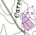
9 FOUNDATION REPORT BCI Job. No US 50 / Latrobe Road West Bound Off-Ramp Undercrossing March 30, 2012 P.M. 0.9, Bridge No K, 03-ED-50, EA 03-2E5101 El Dorado County, California 5 SITE GEOLOGY AND SUBSURFACE CONDITIONS 5.1 Regional Geology The project is located within the foothills of the Sierra Nevada geomorphic province of California. The Sierra Nevada has a general northwest topographic trend and is on the order of 430 miles long and 40 to 80 miles wide. Rock of the Sierra Nevada was created roughly 120 to 130 million years ago when sediments as thick as 30,000 feet along with volcanic rocks were buckled and warped resulting in a series of low mountain ranges. The roots of these mountain ranges were then intruded by granitic rock. The Sierra Nevada was tilted upward as a result of faulting along the east edge of the mountain ranges. In the higher elevations of the Sierra Nevada, much of the older sedimentary rock has been eroded to expose granitic rock. Older rocks that remain have been metamorphosed and are exposed in the foothills of the Sierra Nevada. Most of El Dorado County is underlain by Mesozoic-age metavolcanic and metasedimentary rocks. The metamorphic rock structure is dominated by a series of northwest-trending faults and fault zones that mark the boundaries of various rock types. 5.2 Local Geology and Faulting Published geologic mapping by Wagner 1 and Busch 2 shows Jurassic-age metavolcanic and metasedimentary rock throughout the project area. The mapping also shows the north-south trending West Bear Mountains Fault (a.k.a., Prairie Creek-Spenceville-Deadman Fault per Caltrans) about 1,000 feet east of the Latrobe Road UC. We show local site geology and faulting on Figure 2 (based on Busch, 2001). West of the West Bear Mountains Fault, the referenced mapping shows metavolcanic rock associated with the Copper Hill Volcanics ( mostly mafic to andesitic pyroclastic rocks, lava and pillow lava; subordinate felsic porphyritic and pyroclastic rocks ) and metasedimentary rock associated with the Salt Springs Slate ( mostly dark gray slate with subordinate tuff, greywacke and rare conglomerate ). East of the West Bear Mountain Fault, mapped geology is shown as ophiolitic terrain comprised of metavolcanic rocks ( mafic to felsic; minor sedimentary rock ) and metasedimentary rocks ( slate, quartzite, chert, carbonate rock ). The referenced mapping does not show the project site within an ultramafic rock area. However, ultramafic rocks are mapped nearby. This is a common host rock for naturally occurring asbestos minerals (NOA). Geologic mapping of asbestos containing rocks by Churchill 3 shows 1 Wagner, D.L. et al, Geologic Map of the Sacramento Quadrangle, California, California Geological Survey, Map No. 1A, 1981, revised Busch, Generalized Geologic Map of El Dorado County, California, June, 2001, California Geological Survey, OFR Churchill, et al., 2000, Areas More Likely to Contain Natural Occurrences of Asbestos in Western El Dorado County, California, California Geological Survey, OFR
10 FOUNDATION REPORT BCI Job. No US 50 / Latrobe Road West Bound Off-Ramp Undercrossing March 30, 2012 P.M. 0.9, Bridge No K, 03-ED-50, EA 03-2E5101 El Dorado County, California an area more likely to contain naturally occurring asbestos about one mile north of the Latrobe Road UC and also east of Bass Lake Road (2 miles east of the project). The mapping shows the entire project interval to be within an area that probably does not contain asbestos. Mapping by Bruyn, , shows the project within a Quarter Mile Buffer for More Likely to Contain Asbestos or Fault Line. Churchill discusses the possibility of serpentine occurring in faults or within fault zones, which may contain chrysotile or tremolite/actinolite asbestos. During our surface reconnaissance of the project area and in our subsurface exploration, we did not observe outcrops containing serpentinite, a host rock for NOA, or significant bands of fibrous (asbestiform) minerals within the visible bedrock. As discussed above, NOA mapping does not show the project interval within an ultramafic rock area, although the project is near mapped faults and other areas known to contain naturally occurring asbestos. 5.3 Subsurface Soil and Rock Conditions Caltrans Subsurface exploration performed by the State in December 1962 consisted of five, 1-inch soil tube borings, supplemented by three 2.5-inch diameter cone penetration borings. The cone penetration borings were driven to effective refusal at depths varying from 5 feet to 30 feet using a No. 2 M c Kiernan-Terry air hammer at 115 psi. The foundation study and LOTB drawing indicate that subsurface materials at the site consist of clay and fill underlain by slate [rock]. Appendix A includes the LOTB drawing (January 6, 1964) for those borings Previous Consultant Explorations The referenced Taber Consultants (Taber) reports are the most pertinent to the project. Taber drilled three exploratory borings to a maximum depth of 46 feet below the ground surface (bgs) in February 1999 at the UC location (Taber 2002 report). Taber used solid-stem flight auger and rotary drilling methods to drill through soil and weathered bedrock, and diamond-coring equipment to drill the borings through the less weathered rock. In general, Taber identified metamorphic rock at elevations ranging from approximately 613 ft near Abutment 1 (west end) to 616 ft near Abutment 3 (east end). In the boring completed in El Dorado Hills Boulevard/Latrobe Road near Bent 2, rock was encountered at a depth of about 1.5 ft below the ground surface (approx. elevation of 603 ft). In the boring at El Dorado Hills Blvd/Latrobe Road and the boring at Abutment 3, the upper 17 to 20 feet of rock is described as very intensely weathered and fractured. Below these depths and in the boring completed near 4 Bruyn, 2005, Asbestos Review Areas, Western Slope, County of El Dorado, State of California, El Dorado County -5-
11 FOUNDATION REPORT BCI Job. No US 50 / Latrobe Road West Bound Off-Ramp Undercrossing March 30, 2012 P.M. 0.9, Bridge No K, 03-ED-50, EA 03-2E5101 El Dorado County, California Abutment 1, the rock is generally described as moderately to slightly weathered. Fill and native soil overlay the rock. In Appendix A, we include the Taber LOTB information (redrafted) on our LOTB for the project BCI Exploration For this project, BCI primarily used the data from the 1999 Taber LOTB. For the ramp work, we completed an additional trench near Abutment 1 and one boring near Abutment 3. These exploration points confirm the presence of shallow rock near the abutments. We include a soil / rock unit profile with engineering properties in Appendix B. At Abutment 1, rock at and below foundation level (elev. 598) is moderately to slightly weathered, intensely to moderately fractured, and hard to very hard. The Rock Quality Designation (RQD) for cores near foundation level range from 10 to 26%. We classify this rock as having very poor to poor rock mass quality based on Table A, Caltrans Bridge Design Specifications, November At Bent 2, rock at and below foundation level is decomposed to moderately weathered, very intensely to intensely fractured, and very soft to soft. Coring was not necessary at foundation level and SPT blowcounts ranged from 66 to 54 for a 6-inch drive. At Abutment 3, rock at and below foundation level is moderately to slightly weathered, intensely fractured and very hard. RQD for core near foundation level ranges from 0 to 100%. We classify rock as having very poor to fair rock mass quality. Appendix A contains the LOTB drawings for this study which provides more specific soil and rock descriptions and an explanation of descriptive terms used to log soil and rock core. Appendix A also contains the description of the exploration and sampling methods, and laboratory tests conducted on samples obtained during the exploration. 5.4 Groundwater Caltrans The 1963 Caltrans foundation study states Groundwater was not encountered during the field study; however, surface water was present. The April 5, 2000 Memorandum states Groundwater was encountered during the field investigation in December The highest groundwater elevation (per 1963 datum) measured at the site is at elevation m (614.5 ft). The as-built LOTB shows groundwater levels as follows in Table 1: -6-
12 FOUNDATION REPORT BCI Job. No US 50 / Latrobe Road West Bound Off-Ramp Undercrossing March 30, 2012 P.M. 0.9, Bridge No K, 03-ED-50, EA 03-2E5101 El Dorado County, California Table 1 Groundwater Summary from 1963 Foundation Study Boring No. Boring Elevation Measured Groundwater (Ground Surface, ft) Elevation (ft) B B B B Note: Elevations shown are referenced to datum used in Previous Consultant Explorations Taber encountered groundwater at depths ranging between about 7 feet and 14 feet bgs (elevation of feet to feet) in borings completed in February BCI Observations During our subsurface exploration for the Latrobe Road UC (June 2007), we encountered groundwater at a depth of about 36 feet (elevation feet msl) in Boring 07-B2. We did not encounter groundwater within the augered intervals in Borings 07-B1 or 07-B3 to depths of 16 feet (elevation feet) and 5 feet (elevation feet), respectively. We did not obtain groundwater measurements in those borings below the augered intervals due to the presence of drill fluid. During construction of the recent mainline UC improvements (May 2010), we observed groundwater in foundation excavations for the abutments and bent (base of excavation at elevation 598 feet). This water required pumping for removal prior to placement of concrete. Foundation excavation was completed during a very wet spring season. In general, we expect: overburden soils and upper portions of decomposed rock to be seasonally saturated shallow groundwater and seepage along the soil/rock interface and within shallow, fractured rock during the winter months or extended periods of rainfall groundwater within the underlying less-weathered rock to be discontinuous, likely transmitted as seepage through rock discontinuities (e.g., fractures, joints, etc.). -7-
13 FOUNDATION REPORT BCI Job. No US 50 / Latrobe Road West Bound Off-Ramp Undercrossing March 30, 2012 P.M. 0.9, Bridge No K, 03-ED-50, EA 03-2E5101 El Dorado County, California 6 CORROSION EVALUATION 6.1 Previous Studies Taber Consultants evaluated soil corrosivity for previous studies made within the project area in the vicinity of the Latrobe Road UC. Laboratory test results indicate a non-corrosive soils environment as defined by the September 2003 Caltrans Corrosion Guidelines publication. 5 BCI evaluated soil and weathered rock samples obtained during our site exploration for the adjacent mainline UC project. Test results for that project also indicate a non-corrosive soils environment. Table 2 presents those corrosivity test results. Boring and Sample Depth (ft) Table 2 - Soil Corrosion Test Summary Approx. Minimum Chloride Elevation Resistivity ph Content (ft) (Ohm-cm) (ppm) Sulfate Content (ppm) B , B1, Run , B , The laboratory test results indicate a non-corrosive soils environment as defined by the Caltrans Corrosion Guidelines publication (2003). 6.2 Current Study BCI completed an additional corrosion test on a sample of weathered rock from Boring A near Abutment 3. Test results indicate the following: Chloride content of 4 ppm Sulfate content was non-detectable Minimum resistivity of 2,931 Ohm-cm ph of 8.67 The additional test supports a non-corrosive soils/weathered rock environment. Appendix A contains the test result. 5 Caltrans considers a site to be corrosive to foundation elements if one or more of the following conditions exist: 1) Chloride concentration is greater than or equal to 500 ppm, 2) sulfate concentration is greater than or equal to 2000 ppm, or 3) ph is 5.5 or less (Corrosion Guidelines, Version 1.0, 2003). -8-
14 FOUNDATION REPORT BCI Job. No US 50 / Latrobe Road West Bound Off-Ramp Undercrossing March 30, 2012 P.M. 0.9, Bridge No K, 03-ED-50, EA 03-2E5101 El Dorado County, California 7 NATURALLY OCCURRING ASBESTOS Previous studies referenced above include laboratory tests on rock to evaluate the presence of naturally occurring asbestos. None of the samples tested detected the presence of naturally occurring asbestos minerals at or near the bridge site. BCI evaluated soil/rock samples obtained during the subsurface exploration for the mainline UC for the presence of naturally occurring asbestos (NOA). Asbestos TEM Laboratories, Inc. tested the samples in accordance with the California Air Resources Board (CARB) Method 435 for determination of asbestos. For the adjacent Latrobe Road UC project, laboratory test results on two samples, Sample ID: LB-2-1 II and LB-2-5 III, show <0.25% Actinolite and None Detected, respectively. 8 SEISMIC DATA AND EVALUATION 8.1 Geologic Hazards Published mapping does not show landslide features within the project interval. Based on our review, existing fill and cut slopes in the project area have performed well and appear stable. The high, north facing, rock cut on the eastbound off-ramp (south side of US 50) has experienced some slab, and wedge failures due to the steepness of the slope and exposure of discontinuities with unfavorable orientation; these conditions are not present near the west bound off-ramp UC. We did not observe significant geologic hazards (such as landsliding, settlement, soft soils, severe erosion, springs, etc) during our review of the subject site. 8.2 Seismic Study Ground Motion Study Based on Caltrans ARS Online (V1.0.4) and other mapping, the closest recognized Late Quaternary or younger fault is the Bear Mountains Fault Zone (Rescue Fault section, Caltrans Fault ID No. 83, Maximum Magnitude, MMax = 6.5) located approximately 8.75 miles (14 km) east of the site. Figure 3, Seismic Hazard Map in Appendix A, shows the approximate fault locations. We used the Caltrans ARS Online (web-based tool) to calculate both deterministic and probabilistic acceleration response spectra for the site based on criteria provided in Appendix B of the Caltrans Seismic Design Criteria (Revision Date:11/2010). Caltrans design spectrum is based on the larger of the deterministic and probabilistic spectral values. The deterministic spectrum is determined as the average of median response spectra calculated using ground motion prediction equations developed under the Next Generation Attenuation -9-
15 FOUNDATION REPORT BCI Job. No US 50 / Latrobe Road West Bound Off-Ramp Undercrossing March 30, 2012 P.M. 0.9, Bridge No K, 03-ED-50, EA 03-2E5101 El Dorado County, California (NGA) project. These equations are applied to all faults considered to be active in the last 750,000 years (late-quaternary age) that are capable of producing a moment magnitude earthquake of 6.0 or greater. The probabilistic spectrum is obtained from the USGS (2008) National Hazard Map for 5% probability of exceedance in 50 years. Probabilistic analysis includes deaggregation for applicable fault distance when near-fault effects apply (as for the UC site). Both the deterministic and probabilistic spectra account for soil effects through incorporation of the parameter Vs30, the average shear wave velocity in the upper 30 meters of the soil profile. For the project site, we assume a Site Class B/C with Vs30 equal to 760 meters per second (approximately 2,500 feet per second) based on the mapped ground conditions (underlain by shallow metamorphic rock). In general, the minimum deterministic spectra controls at shorter site periods and the probabilistic spectra controls at longer periods (above about 0.9 seconds). The peak ground acceleration (PGA) at the site is approximately 0.2g based on Caltrans ARS Online and minimum deterministic levels of ground acceleration. We present data points for site spectra in the Table 3 below and graphed site spectra in Figure
16 FOUNDATION REPORT BCI Job. No US 50 / Latrobe Road West Bound Off-Ramp Undercrossing March 30, 2012 P.M. 0.9, Bridge No K, 03-ED-50, EA 03-2E5101 El Dorado County, California Table 3 - Caltrans ARS Online Envelope* Spectrum Data Period SA Period SA Period SA Period SA * Envelope data for this site is a combination of the Minimum Deterministic Spectra and Probabilistic Spectra Liquefaction Evaluation Liquefaction can occur when saturated, loose to medium dense, granular soils (generally within 50 feet of the surface), or specifically defined cohesive soils, are subjected to ground shaking. Rock is present at shallow depths throughout the project site. We consider the potential for detrimental soils liquefaction to be very low to nonexistent. -11-
17 FOUNDATION REPORT BCI Job. No US 50 / Latrobe Road West Bound Off-Ramp Undercrossing March 30, 2012 P.M. 0.9, Bridge No K, 03-ED-50, EA 03-2E5101 El Dorado County, California Fault Rupture The site does not lie within or adjacent to an Alquist Priolo Earthquake Fault Zone for fault rupture hazard (Bryant and Hart, 2007) 6, and no known active faults cross the project location. The referenced mapping by Busch shows the main trace of the West Bear Mountains Fault (Prairie Creek-Spenceville-Deadman Fault) crossing US 50 about 1,000 feet east of Latrobe Road and a north-south trending splay associated with this fault crossing US 50 about 3,000 feet east of the Latrobe Road. Jennings (1994) 7 shows the West Bear Mountains Fault as Pre- Quaternary in age (>1.6 million years), considered inactive. The Caltrans Deterministic PGA Map (September 2007) does not show this fault as an active seismic source and shows no active faults in the project area. The closest fault considered in ground motion analysis is the East Bear Mountains Fault (or Rescue section, Caltrans Fault Identification No. 83) located approximately 8 miles east of the site (see Figure 3). We consider the potential for fault rupture at the site to be low Seismic Settlement During a seismic event, ground shaking can cause densification of granular soil above the water table that can result in settlement of the ground surface. As discussed above, rock is present at shallow depth throughout the site. We consider the possibility of detrimental seismic settlement at this site to be low when embankment fills are constructed in accordance with Caltrans specifications Seismic Slope Instability We consider the potential for seismic slope instability in the form of landslides and mudslides at this site to be very low to nonexistent. Similarly, we consider the potential for seismically induced rockslides or rockfall on engineered cut/fill slopes constructed no steeper than 1.5H:1V to be very low. 9 AS-BUILT FOUNDATION DATA The Caltrans April 5, 2000 Memorandum presents a summary of the existing Latrobe Road UC, Bridge No LR foundations. Table 4 below summarizes the foundation data obtained from the as-built plans, foundation report and the memorandum. 6 Fault Rupture Hazard Zones in California, Special Publication 42, Interim Revision; California Geological Survey 7 Fault Activity Map of California and Adjacent Areas, Geologic Map No. 6, California Division of Mines and Geology -12-
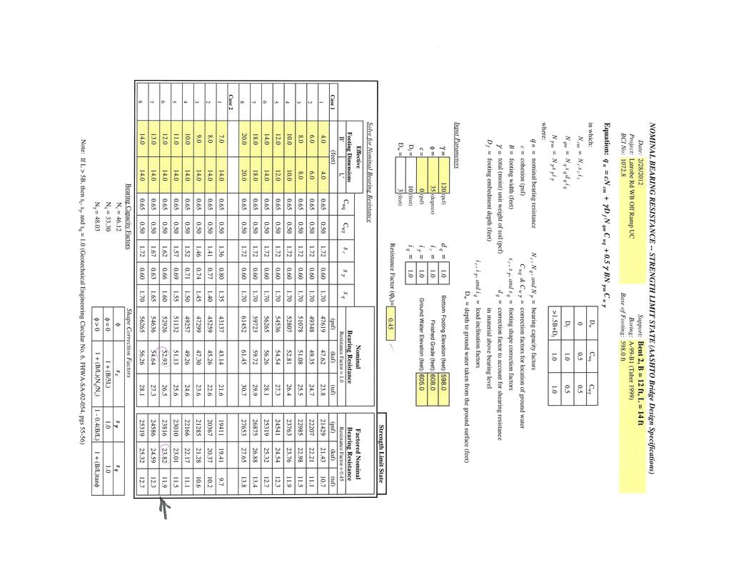
18 FOUNDATION REPORT BCI Job. No US 50 / Latrobe Road West Bound Off-Ramp Undercrossing March 30, 2012 P.M. 0.9, Bridge No K, 03-ED-50, EA 03-2E5101 El Dorado County, California Table 4 - As-Built Foundation Data for Latrobe Road UC, Bridge No LR Location Foundation Type Design Bearing Capacity (tsf) Pile Design Loading (ton) R/L Elevation* (ft) Abutment 1R/1L 10 BP 42 H-Pile /600 Bent 2R 600/600 Bent 2L 600/600 Bent 3R Spread Footing, 8 ft 599.2/ Bent 3L square by 2 ft thick 601/601 Bent 4R 600.5/601 Bent 4L 601/601 Abutment 5R/5L 10 BP 42 H-Pile /605.2 * Bottom of footing elevation and average tip elevations. The average tip elevations shown on the as-built plans vary slightly from the average taken from the pile driving records. The values presented are the averages obtained from the pile driving records. Elevations shown in the table are referenced to datum used in 1963 for original study, and are approximately 2.6 feet lower than current NAVD 88 project datum. All piles were driven using a Delmag D12 Diesel hammer. For the right bridge abutments, embankment fill was predrilled prior to driving piles. Predrilling was not required for the left bridge abutments. The spread footing at Bent 3 (right bridge, right column) was overexcavated 1.8 feet below the planned elevation. The spread footing at Bent 4 (right bridge, right column) was overexcavated 0.5 feet below the planned elevation. As-built information has not yet been released for the mainline bridge replacement project in 2010 but the design foundation information is as follows in Table 5: Support Location Table 5 Foundation Design Information for Latrobe Mainline Bridge Replacement WSD LRFD (LRFD Spread Service-I Footing Size Strength Limit State Service (ft) Load b = 0.45 Combination) B L Bottom of Footing Elevation (ft) Minimum Footing Embedment Depth (ft) Allowable Gross Bearing Capacity (ksf) Permissible Net Contact Stress (ksf) Factored Gross Nominal Bearing Resistance (ksf) Extreme Event b = 1.0 Factored Gross Nominal Bearing Resistance (ksf) Abut N/A N/A N/A Bent N/A Abut N/A N/A N/A It is our understanding, based on limited observation during construction and discussion with others, that the fractured and weathered nature of the rock allowed for foundation excavation with conventional equipment (significant chiseling was not necessary). -13-
19 FOUNDATION REPORT BCI Job. No US 50 / Latrobe Road West Bound Off-Ramp Undercrossing March 30, 2012 P.M. 0.9, Bridge No K, 03-ED-50, EA 03-2E5101 El Dorado County, California 10 FOUNDATION RECOMMENDATIONS We consider the most appropriate foundation type at this site to be spread footings established within the underlying rock unit. Below, we provide specific recommendations for spread footing foundations established within weathered rock. Site foundation characteristics/ constraints affecting details of support level and bearing include: depth to rock and variation of rock surface along individual support lines hard rock excavation to bearing levels mechanical defects of the rock (fractures/joints) potential presence of semi-detached blocks of rock or overbreak within footing excavations Alternatively, Cast-In-Drilled-Hole (CIDH) piles or large diameter drilled-shafts (at the bent) can be considered at this site, particularly if resistance to high uplift and lateral load demands is required. Such piles would need to be 24-inch (minimum) diameter in consideration for potential ground water and likely require difficult excavation within variably hard rock. CIDH pile tip elevations would depend on pile/shaft diameter and defined compressive, tensile and lateral loading requirements. We do not expect that driven (displacement) piles will achieve adequate penetration for stability and do not recommend their use. Steel H-piles could be considered at the abutments but they would be short (some likely 12 feet), achieve only very limited rock penetration (i.e., point bearing only), and provide little lateral or tensile resistance Spread Footing Data Table Based on footing foundation design data provided by QEI and our geotechnical analysis, we provide spread footing foundation design recommendations in Table 6. A discussion of our analyses follows. -14-
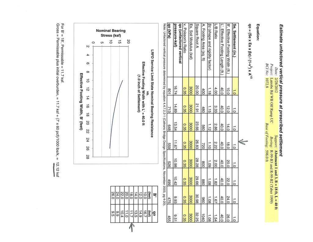
20 FOUNDATION REPORT BCI Job. No US 50 / Latrobe Road West Bound Off-Ramp Undercrossing March 30, 2012 P.M. 0.9, Bridge No K, 03-ED-50, EA 03-2E5101 El Dorado County, California Support Location Footing Size (ft) B L Table 6 Spread Footing Data Table Foundation Design Recommendations for Spread Footings 1, 2 Bottom of Footing Elevation (ft) 3 Minimum Footing Embedment Depth (ft) WSD (LRFD Service-I Limit State Load Combination) Permissible Gross Contact Stress (ksf) Allowable Gross Bearing Capacity (ksf) Service Permissible Net Contact Stress (ksf) LRFD Strength b = 0.45 Factored Gross Nominal Bearing Resistance (ksf) Extreme Event b = 1.0 Factored Gross Nominal Bearing Resistance (ksf) Abut N/A N/A N/A Bent N/A N/A Abut N/A N/A N/A Notes: 1) Recommendations are based on the foundation geometry and loads provided by the Design Engineer. The footing contact area is taken as equal to the effective footing area, where applicable. 2) See Memo to Designers (MTD) 4-1 for definitions and applications of the recommended design parameters. 3) Footing elevation conforms to QEI Foundation Plan 4) Footing length will be extended 27.5 ft for wall footing (between existing and new structure) BCI determined the values shown above based on Working Stress Design (WSD) at the abutments and Load and Resistance Factor Design (LRFD) at the bent. Our recommendations are based on specific loads provided by the design engineer for the foundation geometry shown in the Spread Footing Data Table. We conservatively modeled the rock at foundation level as a dense, gravelly soil with groundwater near the surface (elevation of approximately 603 feet). We include footing foundation design data provided by QEI and our spread footing design calculations in Appendix B Settlement We determined the total settlement of spread footing foundations at all supports based on elastic settlement theory and conservatively modeled the rock as a dense, gravel soil. For spread footings established as above, we estimate that settlement will be nominal (less than 1-inch) and will occur substantially during construction. We expect differential settlement to be less than one-half of the total settlement. We include our settlement calculations in Appendix B. Due to the presence of rock at foundation level, induced settlement at existing, adjacent structure locations (mainline bridge abutments) will be insignificant. -15-
21 FOUNDATION REPORT BCI Job. No US 50 / Latrobe Road West Bound Off-Ramp Undercrossing March 30, 2012 P.M. 0.9, Bridge No K, 03-ED-50, EA 03-2E5101 El Dorado County, California 10.3 Lateral Load Resistance Calculate lateral load resistance of spread footings for seismic or other transient loads as follows: A soil friction factor (tan δ) of 0.45 for cast in-place concrete foundations bearing on intact rock materials. An allowable passive pressure of 250 pcf equivalent fluid pressure against the face of the footing (based on formed footings with compacted structure backfill or footings poured neat against intact rock), with a resistance factor ( ) of 0.5. Passive and friction resistance may be combined Retaining Walls New retaining walls (Type 1) are planned along the north side of each abutment. The planned length, height, and bottom of footing elevation for the walls are as follows in Table 7: Support Location Table 7 Abutment Retaining Wall Summary Total Length (feet) Height (feet) Base of Footing Elevation for Type 1 Retaining Wall (feet) Abut , 22, and 24 Steps up from 602 to 610 Abut , 20, and 24 Steps up from 602 to 610 For Type-1 retaining walls with level backfill (Case 1) condition, Caltrans Standard Plans indicate maximum toe pressures of 3.5 ksf to 4.9 ksf for retaining wall heights between 16 feet and 24 feet high. We expect the planned retaining walls established at or below elevation 610 feet at Abutment 1 and Abutment 3 to engage intact, weathered rock. Minor engineered fill (Structure Backfill) prism may occur below the wall foundations due to excavation and backfill for adjacent abutment foundations (at elevation 598 ft). Adequate bearing capacity is available for maximum toe pressures indicated for the Caltrans Type-1 retaining wall foundations established within intact weathered rock (or engineered fill prism) at or below elevation 610 feet at Abutment 1 and 3. Maximum and differential settlements across and along the walls will be less than 1-inch. We expect that settlement will occur substantially during construction. -16-
22 FOUNDATION REPORT BCI Job. No US 50 / Latrobe Road West Bound Off-Ramp Undercrossing March 30, 2012 P.M. 0.9, Bridge No K, 03-ED-50, EA 03-2E5101 El Dorado County, California 10.5 Approach Fill Earthwork Fill Material We assume locally excavated soil/weathered rock will be used for construction of approach fills at this location. The source of borrow material for construction of approach fills has not been identified. Proposed borrow must be tested and approved for use by the project engineer prior to transporting to the site Expansive Material Expansive materials shall not be placed as part of the embankment within the limits of the bridge abutment for the full width of the embankment. Place only material with a low expansion potential. Low expansion material is defined as having an Expansion Index (EI) less than 50 (per ASTM D4829), and a Sand Equivalent (SE) greater than 20 (per California Test 217) Geometry and Stability Where approach fill is placed, side slopes will have a gradient of 2H:1V or flatter. The proposed geometry is a common slope gradient considered stable for typical approach fill construction. We assume abutment backfill will consist of materials conforming to Structure Backfill requirements. The mostly moderate slope of the existing ground surface and high strength of the underlying rock will provide a stable base on which to construct the fills. Foundations supported on or near a fill slope are not proposed Site Preparation In the area of approach fills, clear and grub existing slopes in accordance with the Caltrans Standard Specifications, Section 16. Construct structure backfill at the abutments in accordance with the Standard Specifications, Section Construct the embankment approach fills in accordance with the Standard Specifications, Section , including at least 95% relative compaction on all fill within 150 ft of bridge abutments Settlement Due to the presence of shallow rock, we do not anticipate significant settlement at approach fills. We expect post-construction settlement between the abutment backwall and adjacent approach fills/backfill to be less than ½-inch, provided structure backfill is compacted in accordance with the Standard Specifications. A waiting period is not necessary. -17-
23 FOUNDATION REPORT BCI Job. No US 50 / Latrobe Road West Bound Off-Ramp Undercrossing March 30, 2012 P.M. 0.9, Bridge No K, 03-ED-50, EA 03-2E5101 El Dorado County, California 11 LATERAL EARTH PRESSURES We assume that the approach fill material meets the requirements of Caltrans standard for Structure Backfill. To determine equivalent fluid weights (EFWs), we use Caltrans specified materials with a soil unit weight of approximately 120 pcf, a minimum angle of internal friction equal to 33 degrees, and an assumed drainage material behind the walls. Use the following EFWs to design the abutments walls and wing walls at Abutments 1 and 3: Condition EFW Static EFW Seismic Active 36 lb/ft 3 40 lb/ft 3 At-Rest 55 lb/ft 3 62 lb/ft 3 Passive 270 lb/ft lb/ft 3 The values shown above assume level backfill conditions and that drainage is placed behind walls in accordance with Caltrans Standard Plans and Specifications. To limit wall deflection to acceptable levels, BCI applied a factor of safety of 1.5 to the ultimate passive pressure to generate the allowable passive pressures provided above. We estimate the EFWs for seismic loading using the Mononobe-Okabe equation for active and passive lateral coefficients K a and K p. We estimated the at-rest coefficient, K o, for the seismic condition using an increase ratio similar to the active condition. In the Mononobe-Okabe equation, BCI used a horizontal seismic acceleration coefficient (k h ) of 0.10 calculated using the equation in Chapter 11, Section of the AASHTO LRFD Bridge Design Specifications-4th Edition. This k h value assumes that the walls displace at least 1-inch during the design seismic event. We calculated the above static EFWs using methods presented in the 1982 Naval Facilities (NAVFAC) Design Manual 7.2. Apply the resultant of the seismic active and at-rest pressures at a depth 0.5H from the base of the wall, where H equals the wall height. For surcharge loads, apply an additional uniform lateral load behind the wall equivalent to 0.30 times the surcharge pressure. Use a soil friction factor (tan δ) of 0.45 for cast in-place concrete foundations bearing on weathered rock. The passive pressures are applicable for concrete placed directly against undisturbed soil/weathered rock or compacted fill. For seismic loading into abutments, use a maximum passive pressure of 5.0 ksf for longitudinal abutment response, with the proportionality factor presented in Section of Caltrans Seismic Design Criteria v
24 FOUNDATION REPORT BCI Job. No US 50 / Latrobe Road West Bound Off-Ramp Undercrossing March 30, 2012 P.M. 0.9, Bridge No K, 03-ED-50, EA 03-2E5101 El Dorado County, California 12 CONSTRUCTION CONSIDERATIONS 12.1 Excavation and Shoring We expect that excavation of soils can be achieved using typical heavy-duty construction equipment and that excavation of weathered rock within footing limits to depths indicated above will be locally difficult, but generally achievable without blasting. Use of air tools/chiseling may be necessary. Rock blasting may disrupt/degrade integrity of the surrounding rock and the adjacent bridge structures (particularly at the abutments). Therefore, rock blasting should not be permitted. The contractor is responsible for design and construction of excavation sloping and shoring in accordance with Cal OSHA requirements and the Caltrans Trenching and Shoring Manual. Native soils and weathered rock can be classified as Type B soils in accordance with Cal OSHA. Particular consideration for shoring will be required for local areas of weak rock, existing embankment fill, areas exhibiting potential for failure along daylighting fracture planes, and to protect existing bridge supports. Particular consideration will be required to protect the existing bridge abutments during construction Foundation Construction Place footing concrete neat (without forming), against trimmed, intact bearing material within clean and dry excavations. If forming is necessary, backfill excavations outside footing limits with lean concrete or suitable granular backfill (i.e. Structure Backfill per Caltrans Standard Specifications ) compacted to at least 95% relative compaction (per CTM 216). If it is necessary to deepen footing excavations to engage suitable bearing materials, it is acceptable to backfill with structural concrete to plan footing grade, up to a depth of 3 feet below the footing, with BCI approval. Any exposed open joint/fractures should be evaluated by a BCI Engineering Geologist with respect to bearing/stability considerations and cleaned/surfacedgrouted, if necessary Foundation Monitoring During construction, we recommend placement of monitoring points on the existing footings adjacent to new construction, and frequent surveying for movement. In the event significant (>¼-inch horizontal or vertical) movement of the existing foundations is detected, contact BCI immediately for consultation to evaluate movement and consider mitigations, if necessary. -19-
25 FOUNDATION REPORT BCI Job. No US 50 / Latrobe Road West Bound Off-Ramp Undercrossing March 30, 2012 P.M. 0.9, Bridge No K, 03-ED-50, EA 03-2E5101 El Dorado County, California 12.4 Dewatering We do not anticipate the presence of groundwater within footing excavations during dry season construction (July through October). If/where seepage is encountered, we expect it can be controlled with sump pumps Naturally Occurring Asbestos Based on the previous test results at the mainline bridge location, testing in adjacent areas completed by BCI for the other ramp work, and observed rock conditions, BCI considers the risk of encountering rock with significant quantities of NOA minerals to be low. However, considering the occurrence of NOA in the vicinity of the project, we recommend preparation of an Asbestos Hazard Mitigation Plan in compliance with provisions of El Dorado County Air Quality Management District (EDAQMD) Rule and California Air Resources Board requirements. Visually monitor rock types exposed during construction for the potential presence of naturally occurring asbestos (NOA) minerals. If construction activities expose NOA, comply with the applicable provisions of EDAQMD Rule and the State of California Asbestos Airborne Toxic Control Measure (ACTM), CCR Title 17, Section In addition, prepare a worker health and safety program for excavations in areas with NOA in accordance with all regulatory requirements, including CAL OSHA Storm Water Quality We expect that construction term erosion control will be available by means of typical good construction practices (e.g., use of erosion barriers, synthetic slope covers, hydro-seeding, etc.). This project will involve earthwork and we expect that the contractor will develop a Storm Water Pollution Prevention Plan, specific for this project. 13 RISK MANAGEMENT Our experience and that of our profession clearly indicates that the risks of costly design, construction, and maintenance problems can be significantly lowered by retaining the geotechnical engineer of record to provide additional services. For this project, BCI should be retained to: Review and provide written comments on the (civil, structural) plans and specifications prior to construction. -20-
26 FOUNDATION REPORT BCI Job. No US 50 / Latrobe Road West Bound Off-Ramp Undercrossing March 30, 2012 P.M. 0.9, Bridge No K, 03-ED-50, EA 03-2E5101 El Dorado County, California Monitor construction to check and document our report assumptions. At a minimum, review bridge and wall foundation excavations to observe foundation conditions for the presence of open joints / fractures (or other defects), and confirm bearing materials and treatment of rock defects (if/as necessary). Update this report if design changes occur, two years or more lapse between this report and construction, and/or site conditions change If BCI is not retained to perform the above applicable services, we are not responsible for any other parties interpretation of our report, and subsequent addenda, letters, and discussions. 14 LIMITATIONS BCI performed services in accordance with the generally accepted geotechnical standard of practice currently used in this area. Where referenced, we used CTM and ASTM standards as a general (not strict) guideline only. We do not warranty our services. BCI also based this report on the current site and project conditions. We assumed the soil/rock and groundwater conditions encountered at our exploration points and those by others are representative of the subsurface conditions across the site. Actual conditions between borings could be different. Groundwater may be higher in other locations and times than measured in the borings. The interface between soil and rock types on the logs is approximate. The transition between soil and rock types may be abrupt or gradual. We base our recommendations on the final logs, which represent an interpretation of the field logs and general knowledge of the site and geological conditions. Our scope did not include evaluation of flooding or hazardous materials on site. This Report should only be used for design and construction of the Latrobe Road West Bound Off-Ramp Undercrossing, as described herein. We provide a separate Geotechnical Design/Materials Report for the overall project and a Limited Phase II Assessment for hazardous materials. Modern design and construction are complex, with many regulatory sources, restrictions, involved parties, construction alternatives, etc. It is common to experience changes and delays. The owner should set aside a reasonable contingency fund based on complexities and cost estimates to cover changes and delays. -21-
27 Figures Figure 1 Vicinity Map Figure 2 Geologic Map Figure 3 Seismic Hazard Map Figure 4 ARS Curve Geotechnical Geo-Environmental Construction Services Forensics


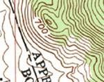
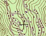
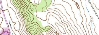
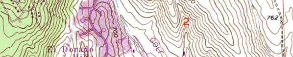
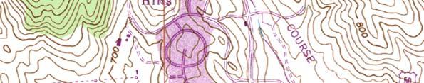
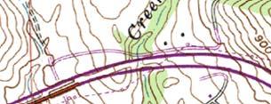
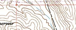
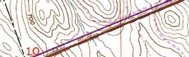
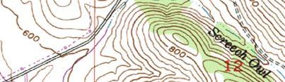
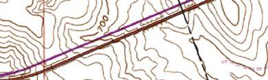
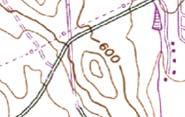
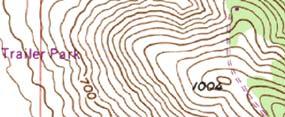
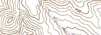
28 Dist County Route Total Project 03 ED 50 PM 0.9 SITE To Folsom Source: MAPTECH Terrain Navigator Pro, v. 8.0, USGS topographic 7.5 minute quadrangle, Clarksville, 1953 (revised 1980). 1:24, Blocker Drive, Ste 110 Auburn, CA Phone: (530) Fax: (530) Fax VICINITY MAP File No State Route 50 Latrobe Rd Undercrossing Bridge No K, EA 03-2E5101 El Dorado County, California March 2012 Figure 1
 887--1494 Fax: (530) 887-1495 www.")

29 Latrobe Road Undercrossing 1:100,000 1:100,000 L E G E N D 2/23/ Geologic Map Fig 2.dwg Geologic Symbols Blocker Drive, Suite 110 Auburn,CA Phone: (530) Fax: (530) Source: Generalized Geologic Map of El Dorado County, California by Lawrence L. Busch, June GEOLOGIC MAP State Route 50 Latrobe Rd Undercrossing Bridge No K, EA 03-2E5101 El Dorado County, California File No March 2012 Figure 2
30 Bear Mountain fault zone (Hwy 49 fault section) «49 Dist County Route Total Project 03 ED 50 PM 0.9 Bear Mountain fault zone (Deadman fault section) Bear Mountain fault zone (Dewitt fault section) Bear Mountain fault zone 80 «49 (Rescue fault section) tu 50 Sacramento tu 50 SITE LOCATION «49 Legend Surface Faults Peak Ground Acceleration Contours (fraction of gravity) :500,000 Lodi Source: Martha Merriam, et. al., Caltrans Deterministic PGA Map, Blocker Drive, Ste 110 Auburn, CA Phone: (530) Fax: (530) Fax SEISMIC HAZARD MAP State Route 50 Latrobe Rd Undercrossing Bridge No K, EA 03-2E5101 El Dorado County, California (Poorman Gulch fault section) Bear Mountain fault zone File No March 2012 Figure 3
31 ARS Curve (5% Damping) 0.6 Spectral Acceleration, Sa (g) ARS Curve MMax =6.5 PGA = 0.20g Period (sec) Reference: Geotechnical Services Design Manual (Version 1.0, August 2009) and Caltrans Seismic Design Criteria, Appendix B, Revised 11/ Blocker Drive, Ste 110 Auburn, CA Phone: (530) Fax: (530) ARS CURVE State Route Latrobe Rd Undercrossing Bridge No K, EA 03-2E5101 El Dorado County, California File No March 2012 Figure 4
32 APPENDIX A Subsurface Exploration Summary Laboratory Test Results Log of Test Borings Latrobe Road WB Off-Ramp UC (Sheets 1 through 4) Latrobe Road Undercrossing (BCI, August 2007) General Plan Foundation Plan Geotechnical Geo-Environmental Construction Services Forensics
33 FOUNDATION REPORT BCI Job. No US 50 / Latrobe Road West Bound Off-Ramp Undercrossing March 30, 2012 P.M. 0.9, Bridge No K, 03-ED-50, EA 03-2E5101 El Dorado County, California SUBSURFACE EXPLORATION SUMMARY To provide additional subsurface data and confirmation of shallow rock conditions, BCI retained Taber Consultants to drill and sample 1 exploratory borings near the west bound off-ramp UC location. Taber used a CME 75 truck-mounted rig, equipped with 4-inch O.D. solid flight augers, to drill the boring on February 6, 2012 to refusal (in rock) at a depth of 8.5 feet below the ground surface (bgs). Taber obtained relatively undisturbed samples using a Modified California Sampler (equipped with 2.5-inch I.D. brass liners). Samplers were driven into the ground with a 140 pound, automatic hammer falling 30 inches. The test trench was excavated by Monte Ricky Excavation using a CAT 430-D backhoe equipped with an 18-inch wide bucket. BCI obtained bulk samples from the excavation. BCI s geologist logged the boring and trench consistent with the Unified Soil Classification System (USCS) and Caltrans 2010 logging manual, and noted the degree of weathering, fracture density, and hardness. BCI also made groundwater water observations during exploration operations. At the completion of field work, the explorations were backfilled with cuttings. BCI s boring and trench locations and elevations were determined by field estimation (they were not surveyed). Taber completed 3 borings at the bridge site in For the drilling and sampling methods used to advance these borings, refer to the LOTB.
34 FOUNDATION REPORT BCI Job. No US 50 / Latrobe Road West Bound Off-Ramp Undercrossing March 30, 2012 P.M. 0.9, Bridge No K, 03-ED-50, EA 03-2E5101 El Dorado County, California LABORATORY TEST RESULTS BCI performed laboratory tests on selected samples obtained from the exploratory borings. Tests included: ph/minimum Resistivity (CTM 643) Chloride (CTM 422) Sulfate (CTM 417) BCI performed laboratory tests in substantial conformance with the designated test procedure. The test results are attached. The following table summarizes the NOA test results from the mainline bridge replacement project (BCI, 2008). Naturally Occurring Asbestos (NOA) Test Summary US 50 HOV Lane Project Mainline Bridge Replacement Location Line Station Sample Depth Elevation % ID (ft) (ft, msl) Asbestos Type Latrobe A LB-2-1 II ND N/A Road UC A LB-2-5 III <0.25% Actinolite
35 11521 Blocker Drive, Suite 110 (530) Auburn, CA fax: (530) Minimum Resistivity and ph Test Results File No.: Project Name: SR 50 HOV Westbound Ramps Date: 2/14/2012 Sample ID Minimum Resistivity, ph 15.5 o C A B03 2, Minimum Resistivity and ph performed based on Caltrans Test Method 643

36 NOTES: O R-99-B A-99-B R-99-B A PREPARED FOR THE LOG OF TEST BORINGS 1 OF 4
37 CEMENTATION BOREHOLE IDENTIFICATION CONSISTENCY OF COHESIVE SOILS NOTE: Size in inches. ROTARY BORING HAND BORING DYNAMIC CONE PENETRATION BORING CONE PENETRATION TEST (CPT) SOUNDING SOIL LEGEND PREPARED FOR THE LOG OF TEST BORINGS 2 OF 4
38 GROUP SYMBOLS AND NAMES FIELD AND LABORATORY TESTING APPARENT DENSITY OF COHESIONLESS SOILS MOISTURE PERCENT OR PROPORTION OF SOILS PARTICLE SIZE PREPARED FOR THE SOIL LEGEND LOG OF TEST BORINGS 3 OF 4
39 PERCENT CORE RECOVERY (REC) & ROCK QUALITY DESIGNATION (RQD) BEDDING SPACING LEGEND OF ROCK MATERIALS ROCK HARDNESS WEATHERING DESCRIPTORS FOR INTACT ROCK FRACTURE DENSITY PREPARED FOR THE ROCK LEGEND LOG OF TEST BORINGS 4 OF 4
40
41
42
43
44
45 RE GISTE RED PROFESSIONAL ENGINEER Far side retaining wall shown Far side FG Datum Elev % BB BVC Elev " PROFILE GRADE "W1" LINE Far side R/C=-1.02% per station 1 & VC No Scale 200-0" 100-0" Far side OG Min Vert Clr = 15-6" Future Min Vert Clr Abut 1 Bent 2 = 15-6" Abut EVC Elev % EB INDEX TO PLANS Sheet No Far side shown Far side FG Title General Plan General Notes Deck Contours Foundation Plan Abutment 1 Layout Abutment 3 Layout Abutment Details No. 1 Abutment Details No. 2 Abutment Details No. 3 Bent Layout Bent Details Typical Section retaining wall Concrete Barrier Type 736 Mod, Typ Sheet No " Title Girder Layout No. 1 X REGISTERED CIVIL ENGINEER DATE Girder Layout No. 2 Precast Girder Details Danny J. Architectural Details Mossman 95% SUBMITTAL Construction Sequence No Structure Approach Type N(30S) PLANS APPROVAL DATE Exp Structure Approach Drainage The County or its officers or agents CIVIL Details shall not be responsible for the accuracy or Log of Test Borings 1 of 4 completeness of electronic copies of this plan sheet. Log of Test Borings 2 of 4 Log of Test Borings 3 of 4 QUINCY ENGINEERING, INC Log of Test Borings 4 of Ramos Circle 8-0" 12-0" -2% & Varies 38-11" DIST COUNTY ROUTE 03 ED 50 Sacramento, CA El Dorado County 2850 Fairlane Court Placerville, CA "W1" Line 12-0" Profile Grade POST MILES TOTAL PROJECT 4-0" 0.4/ " 7 SHEET TOTAL No STATE OF CALIFORNIA SHEETS CURVE DATA ELEVATION 1"= " 7 Precast, Prestressed Concrete Box Girder (With Post- Tensioning) R = = " 3 6 T = L = "W1" POT = "L" POT FG Toe of slope, Typ EC Top of slope To El Dorado Hills Blvd R=160 3 BB Elev :1 4 5 Note: The Contractor shall verify all controlling field dimensions before ordering or fabricating any material. 4:1 Bridge Mounted Sign, see Road Plans "L" Line N " W To El Dorado Hills 2:1 N " E To Latrobe PLAN 1"=20 "W1" Line 12-0" 12-0" WB US-50 BY CHECKED LOAD & RESISTANCE LIVE LOADING: HL93 W/"LOW-BOY"; DESIGN FACTOR DESIGN PERMIT DESIGN VEHICLE X D. Mossman/J. Chou M. Katt BY CHECKED BY CHECKED DESIGN OVERSIGHT DETAILS LAYOUT P. Kenny/J. Chou M. Katt D. Mossman/J. Chou M. Katt X BY CHECKED BY PLANS AND SPECS QUANTITIES SPECIFICATIONS SIGN OFF DATE J. Chou E. Dahl K. Gallagher COMPARED X DESIGN GENERAL PLAN SHEET (ENGLISH) (REV.7/16/10) ORIGINAL SCALE IN INCHES FOR REDUCED PLANS 4:1 1 & WB off Ramp 3 EB Elev DEPARTMENT OF TRANSPORTATION 3 PREPARED FOR THE STATE OF CALIFORNIA Tim Osterkamp PROJECT ENGINEER UNIT: FILE => X OG Notes: TYPICAL SECTION MBGR see Road Plans Existing structure 1"=5 Paint Bridge "Br No K" Paint "Latrobe Rd. WB Off Ramp UC" Structure Approach Type N(30S) Existing Latrobe Road Undercrossing "Br No " Concrete Barrier Type 60F, see Road Plans Architectural Treatment, not shown Concrete Barrier Type 60D, see Road Plans Indicates point of minimum vertical clearance For General Notes and Quantities, see "General Notes" sheet. For Spread Footing Data Table, see "Foundation Plan" sheet. BRIDGE NO K POST MILES 0.9 PROJECT NUMBER & PHASE: CONTRACT NO.: 03-2E5101 LATROBE ROAD WB OFF RAMP UC GENERAL PLAN DISREGARD PRINTS BEARING EARLIER REVISION DATES S:\CLIENT\El Dorado\E US US50 HOV Lanes Phase 0\CAD\Bridge\ K-a-gp01.dgn REVISION DATES SHEET 1 OF 23 DATE PLOTTED => 3/27/2012 TIME PLOTTED => 1:45:21 PM USERNAME => _USER_
46 APPENDIX B Footing Data (provided by QEI) Calculations for WSD Design and LRFD Design Geotechnical Geo-Environmental Construction Services Forensics
47 Footing Data Geotechnical Request Form BCI No Blackburn Consulting Page 1 of 2 Transmitted by: From: Patrick Fischer Date: 03/01/2012 Project: Latrobe Road UC WB Off Ramp UC Completed by: Client: Quincy Engineering, Inc. Bridge Designer: Danny Mossman Date Completed: 03/01/2012 Note: Please insert N/A where applicable Support No. Design Method (WSD or LRFD) Finish Grade Elev. (ft) Footing Foundation Design Data BOF Elevation (ft) Footing Size (ft) Permissible Settlement under Service Load (in) * B L Abutment 1 WSD Bent 2 LRFD Abutment 3 WSD *Based on CALTRANS current practice, the total permissible settlement for a shallow footing is one inch for structures with continuous spans or multi column bents, and two inches for simple span structures. Scour Data Support No. Degradation Scour Base Flood Scour (ft) Total Scour (ft) Contraction Local (ft) Abutment 1 N/A N/A N/A N/A Bent 2 N/A N/A N/A N/A Abutment 3 N/A N/A N/A N/A
48 Footing Data Geotechnical Request Form BCI No Blackburn Consulting Page 2 of 2 Support No. Effective Dimensions Vertical (ft) Load (kip) B L LRFD Service Limit State I Total Load Permanent Load * Horizontal Load (kip) Effective Vertical Dimensions (ft) Load (kip) B L Longitudinal Direction Transverse Direction Abutment 1 2,412 N/A N/A N/A N/A 1,112 N/A N/A Bent 2 1, Abutment 3 2,174 N/A N/A N/A N/A 1,026 N/A N/A * See table in the AASHTO LRFD Bridge Design Specifications for components of permanent load. LRFD Strength and Extreme Event Limit States Strength Limit State Extreme Event Limit State Support No. (Controlling Group) (Controlling Group) Vertical Load Effective Dimensions (ft) Vertical Load Effective Dimensions (ft) (kip) B L (kip) B L Abutment 1 N/A N/A N/A 1,112 N/A N/A Bent 2 1, Abutment 3 N/A N/A N/A 1,026 N/A N/A
49
50
51
52

53
NOA ASSESSMENT HARRIS QUARRY MENDOCINO COUNTY, CALIFORNIA TABLE OF CONTENTS
 NOA ASSESSMENT HARRIS QUARRY MENDOCINO COUNTY, CALIFORNIA TABLE OF CONTENTS Introduction... 1 Scope of Services... 1 Project Location and Description... 1 Geologic Setting... 1 Regional Geology... 1 Site
IV. ENVIRONMENTAL IMPACT ANALYSIS G. GEOLOGY AND SOILS
 IV. ENVIRONMENTAL IMPACT ANALYSIS G. GEOLOGY AND SOILS The following section is a summary of the geotechnical report conducted for the proposed project. The Report of Geotechnical Investigation Proposed
Sacramento Modesto Roseville Pleasanton September 19, 2013 Marcia Medina GHD Inc. 417 Montgomery Street, Suite 700 San Francisco, CA Subject: GE
 Sacramento Modesto Roseville Pleasanton September 19, 2013 Marcia Medina GHD Inc. 417 Montgomery Street, Suite 700 San Francisco, CA 94104 Subject: GEOTECHNICAL REPORT AMENDMENT Stonybrook Creek Crossings
Earth Mechanics, Inc. Geotechnical & Earthquake Engineering
 TECHNICAL MEMORANDUM EMI PROJECT NO: 13-116 DATE: October 29, 2013 PREPARED FOR: Mr. Todd W. Dudley / AECOM PREPARED BY: SUBJECT: (Raja) S. Pirathiviraj and Lino Cheang / (EMI) Preliminary Foundation Report
SLOPE STABILITY EVALUATION AND ACCEPTANCE STANDARDS
 INFORMATION BULLETIN / PUBLIC - BUILDING CODE REFERENCE NO.: LABC 7006.3, 7014.1 Effective: 01-01-2017 DOCUMENT NO.: P/BC 2017-049 Revised: 12-21-2016 Previously Issued As: P/BC 2014-049 SLOPE STABILITY
GEOLOGY, SOILS, AND SEISMICITY
 4.9 GEOLOGY, SOILS, AND SEISMICITY 4.9.1 Introduction Information about the geological conditions and seismic hazards in the study area was summarized in the FEIR, and was based on the Geotechnical Exploration
ATTACHMENT A PRELIMINARY GEOTECHNICAL SUMMARY
 ATTACHMENT A PRELIMINARY GEOTECHNICAL SUMMARY Kevin M. Martin, P.E. KMM Geotechnical Consultants, LLC 7 Marshall Road Hampstead, NH 0384 603-489-6 (p)/ 603-489-8 (f)/78-78-4084(m) kevinmartinpe@aol.com
Guidelines for Site-Specific Seismic Hazard Reports for Essential and Hazardous Facilities and Major and Special-Occupancy Structures in Oregon
 Guidelines for Site-Specific Seismic Hazard Reports for Essential and Hazardous Facilities and Major and Special-Occupancy Structures in Oregon By the Oregon Board of Geologist Examiners and the Oregon
Impact : Changes to Existing Topography (Less than Significant)
") 4.2 Land Resources 4.2.1 Alternative A Proposed Action Impact 4.2.1-1: Changes to Existing Topography (Less than Significant) Development of the project site would involve grading and other earthwork as
4.2 Land Resources 4.2.1 Alternative A Proposed Action Impact 4.2.1-1: Changes to Existing Topography (Less than Significant) Development of the project site would involve grading and other earthwork as
Converse Consultants Geotechnical Engineering, Environmental & Groundwater Science, Inspection & Testing Services
 Converse Consultants Geotechnical Engineering, Environmental & Groundwater Science, Inspection & Testing Services Ms. Rebecca Mitchell Mt. San Antonio College Facilities Planning & Management 1100 North
Date: April 2, 2014 Project No.: Prepared For: Mr. Adam Kates CLASSIC COMMUNITIES 1068 E. Meadow Circle Palo Alto, California 94303
 City of Newark - 36120 Ruschin Drive Project Draft Initial Study/Mitigated Negative Declaration Appendix C: Geologic Information FirstCarbon Solutions H:\Client (PN-JN)\4554\45540001\ISMND\45540001 36120
2.10 Geology/Soils/Seismic/Topography
 2.10 Geology/Soils/Seismic/Topography 2.10.1 Regulatory Setting This section discusses geology, soils, and seismic concerns as they relate to public safety and project design. Earthquakes are prime considerations
GEOLOGY AND SOILS. This chapter summarizes geologic and geotechnical aspects of the site as they relate to the Project.
 9 GEOLOGY AND SOILS INTRODUCTION This chapter summarizes geologic and geotechnical aspects of the site as they relate to the Project. This chapter utilizes information from the following reports prepared
June 9, R. D. Cook, P.Eng. Soils Engineer Special Services Western Region PUBLIC WORKS CANADA WESTERN REGION REPORT ON
 PUBLIC WORKS CANADA WESTERN REGION REPORT ON GEOTECHNICAL INVESTIGATION PROPOSED MARTIN RIVER BRIDGE MILE 306.7 MACKENZIE HIGHWAY Submitted by : R. D. Cook, P.Eng. Soils Engineer Special Services Western
IV. ENVIRONMENTAL IMPACT ANALYSIS E. GEOLOGY AND SOILS
 IV. ENVIRONMENTAL IMPACT ANALYSIS E. GEOLOGY AND SOILS The following analysis is based on the Geotechnical Investigation Report, Proposed Mid-Rise Multi- Family Residential Development Project Wetherly
IV. ENVIRONMENTAL IMPACT ANALYSIS E. GEOLOGY AND SOILS
 IV. ENVIRONMENTAL IMPACT ANALYSIS E. GEOLOGY AND SOILS The following section is a summary of the geotechnical report conducted for the Proposed Project. The Geotechnical Engineering Investigation (the
ENGINEER S CERTIFICATION OF FAULT AREA DEMONSTRATION (40 CFR )
") PLATTE RIVER POWER AUTHORITY RAWHIDE ENERGY STATION BOTTOM ASH TRANSFER (BAT) IMPOUNDMENTS LARIMER COUNTY, CO ENGINEER S CERTIFICATION OF FAULT AREA DEMONSTRATION (40 CFR 257.62) FOR COAL COMBUSTION RESIDUALS
PLATTE RIVER POWER AUTHORITY RAWHIDE ENERGY STATION BOTTOM ASH TRANSFER (BAT) IMPOUNDMENTS LARIMER COUNTY, CO ENGINEER S CERTIFICATION OF FAULT AREA DEMONSTRATION (40 CFR 257.62) FOR COAL COMBUSTION RESIDUALS
IV. ENVIRONMENTAL IMPACT ANALYSIS E. GEOLOGY/SOILS
 IV. ENVIRONMENTAL IMPACT ANALYSIS E. GEOLOGY/SOILS Except where otherwise noted, the following Section is based on the Preliminary Geotechnical Investigation, Proposed Medical Office Buildings and Mixed-Use
Should you have any questions regarding this clarification, please contact the undersigned at or (925)
") October 8, 2015 Revised October 13, 2015 Contra Costa Community College District 500 Court Street Martinez, CA 94553 Attention: Ron Johnson Subject: Clarification of Grading Requirements Diablo Valley
October 8, 2015 Revised October 13, 2015 Contra Costa Community College District 500 Court Street Martinez, CA 94553 Attention: Ron Johnson Subject: Clarification of Grading Requirements Diablo Valley
3.18 GEOLOGY AND SOILS
 3.18 GEOLOGY AND SOILS This section discusses geologic resource concerns as they relate to the environment, public safety, and project design both during construction and after completion of the project.
SLOPE STABILITY EVALUATION AND ACCEPTANCE STANDARDS
 INFORMATION BULLETIN / PUBLIC - BUILDING CODE REFERENCE NO.: LAMC 98.0508 Effective: 1-26-84 DOCUMENT NO. P/BC 2002-049 Revised: 11-1-02 Previously Issued As: RGA #1-84 SLOPE STABILITY EVALUATION AND ACCEPTANCE
ENCE 3610 Soil Mechanics. Site Exploration and Characterisation Field Exploration Methods
 ENCE 3610 Soil Mechanics Site Exploration and Characterisation Field Exploration Methods Geotechnical Involvement in Project Phases Planning Design Alternatives Preparation of Detailed Plans Final Design
3.0 SUMMARY OF POTENTIAL GEOTECHNICAL IMPACTS AND MITIGATION MEASURES
 3.0 SUMMARY OF POTENTIAL GEOTECHNICAL IMPACTS AND MITIGATION MEASURES This section summarizes the principal geotechnical conditions that occur in the project area. The potential impact that each condition
Pierce County Department of Planning and Land Services Development Engineering Section
 Page 1 of 7 Pierce County Department of Planning and Land Services Development Engineering Section PROJECT NAME: DATE: APPLICATION NO.: PCDE NO.: LANDSLIDE HAZARD AREA (LHA) GEOLOGICAL ASSESSMENT REPORT
Civil Engineering, Surveying and Environmental Consulting WASP0059.ltr.JLS.Mich Ave Bridge Geotech.docx
 2365 Haggerty Road South * Canton, Michigan 48188 P: 734-397-3100 * F: 734-397-3131 * www.manniksmithgroup.com August 29, 2012 Mr. Richard Kent Washtenaw County Parks and Recreation Commission 2330 Platt
COMMUNITY DEVELOPMENT DEPARTMENT POLICY & PROCEDURE
 COMMUNITY DEVELOPMENT DEPARTMENT POLICY & PROCEDURE Policy No: DSP-OO3 Release Date: January 1, 2014 Effective Date: January 1, 2014 Revision Date: March 1, 2018 TITLE: The City Policy for Site Specific
Appendix M Preliminary Geotechnical Report, SR 32 Widening Project Study Report
 Appendix M Preliminary Geotechnical Report, SR 32 Widening Project Study Report November 3, 2005 Mr. Chris Rockway 7300 Folsom Boulevard, Suite 203 Sacramento, California 95826 Attention: Matt Brogan
CHAPTER GEOLOGICALLY HAZARDOUS AREAS Applicability Regulations.
 CHAPTER 19.07 GEOLOGICALLY HAZARDOUS AREAS 19.07.010 Applicability. Geologically hazardous areas may pose a threat to the health and safety of citizens when incompatible development is sited in areas of
Geotechnical Aspects of the Seismic Update to the ODOT Bridge Design Manual. Stuart Edwards, P.E Geotechnical Consultant Workshop
 Geotechnical Aspects of the Seismic Update to the ODOT Bridge Design Manual Stuart Edwards, P.E. 2017 Geotechnical Consultant Workshop Changes Role of Geotechnical Engineer Background Methodology Worked
10. GEOTECHNICAL EXPLORATION PROGRAM
 Geotechnical site investigations should be conducted in multiple phases to obtain data for use during the planning and design of the tunnel system. Geotechnical investigations typically are performed in
IV. ENVIRONMENTAL IMPACT ANALYSIS E. GEOLOGY/SOILS
 IV. ENVIRONMENTAL IMPACT ANALYSIS E. GEOLOGY/SOILS The following discussion is based upon information contained in the Hollywood Redevelopment Plan Amendment EIR and a letter prepared by Geotechnologies,
SITE INVESTIGATION 1
 SITE INVESTIGATION 1 Definition The process of determining the layers of natural soil deposits that will underlie a proposed structure and their physical properties is generally referred to as site investigation.
Slope Stability Evaluation Ground Anchor Construction Area White Point Landslide San Pedro District Los Angeles, California.
 Slope Stability Evaluation Ground Anchor Construction Area White Point Landslide San Pedro District Los Angeles, California Submitted To: Mr. Gene Edwards City of Los Angeles Department of Public Works
IV. ENVIRONMENTAL IMPACT ANALYSIS E. GEOLOGY AND SOILS
 IV. ENVIRONMENTAL IMPACT ANALYSIS E. GEOLOGY AND SOILS INTRODUCTION This section evaluates potential impacts related to geology, including seismicity, and soils associated with development of the proposed
Setting MOUNTAIN HOUSE NEIGHBORHOODS I AND J INITIAL STUDY 5. ENVIRONMENTAL CHECKLIST 6. GEOLOGY AND SOILS. Issue
 Issue Less Than Significant or No Impact Potential Significant Impact Adequately Addressed in MEIR MEIR Required Additional Review: No Significant Impact Less Than Significant Impact Due to Mitigation
 R-1 Conveyor Relocation Project Legend 0 500 1000 1500 ft. This map is a user generated static output from an Internet mapping site and is for general reference only. Data layers that appear on this map
9. GEOLOGY, SOILS, AND MINERALS
 June 28, 2018 Page 9-1 9. GEOLOGY, SOILS, AND MINERALS This EIR chapter describes the existing geological, soil, and mineral conditions in the planning area. The chapter includes the regulatory framework
KDOT Geotechnical Manual Edition. Table of Contents
 KDOT Geotechnical Manual 2007 Edition The KDOT Geotechnical Manual is available two volumes. Both volumes are very large electronic (pdf) files which may take several minutes to download. The table of
4.9 GEOLOGY AND SOILS
 4.9 GEOLOGY AND SOILS 4.9.1 EXISTING CONDITIONS TOPOGRAPHY AND RELIEF Zone 40 is located in the central portion of Sacramento County. The topography of the county is represented by three physiographic
CEMEX Eliot Quarry. Lake A Evaluation Report. Alameda County, California
 May 7, 2015 May 7, 2015 Project No. GT13-16 Prepared for: CEMEX 5180 Golden Foothills, Parkway El Dorado Hills, California 95762 7400 Shoreline Drive, Ste. 6 Stockton, California 95219 Tel: 209-472-1822
B-1 SURFACE ELEVATION
 5A 5B LOGGED BY El. S. Bhangoo DRILLING CONTRACTOR Pitcher Drilling DRILLING METHOD Rotary Wash BEGIN DATE 12-14-12 SAMPLER TYPE(S) AND SIZE(S) (ID) SPT, MC BOREHOLE BACKFILL AND COMPLETION COMPLETION
(THIS IS ONLY A SAMPLE REPORT OR APPENDIX OFFERED TO THE USERS OF THE COMPUTER PROGRAM
 C A U T I O N!! (THIS IS ONLY A SAMPLE REPORT OR APPENDIX OFFERED TO THE USERS OF THE COMPUTER PROGRAM EQLique&Settle2. THE AUTHOR IS HEREBY RELEASED OF ANY LIABILITY FOR ANY INCORRECT USE OF THIS SAMPLE
Geotechnical Engineering Study, Conifer Senior High School Football Field Improvements, Conifer, Colorado
 2390 South Lipan Street Denver, CO 80223 phone: (303) 742-9700 fax: (303) 742-9666 email: kadenver@kumarusa.com www.kumarusa.com Office Locations: Denver (HQ), Colorado Springs, Fort Collins, and Frisco,
Preliminary Geotechnical Evaluation Gooseberry Point Pedestrian Improvements Whatcom County, Washington SITE AND PROJECT DESCRIPTION
 File No. 12-100 Geotechnical & Earthquake Engineering Consultants Mr. Kevin Brown, P.E. Gray & Osborne, Inc. 3710 168 th Street NE, Suite B210 Arlington, Washington 98223 Subject: Draft Report Preliminary
 Rock Slope Analysis Small and Large Scale Failures Mode of Failure Marklands Test To establish the possibility of wedge failure. Plane failure is a special case of wedge failure. Sliding along
Boreholes. Implementation. Boring. Boreholes may be excavated by one of these methods: 1. Auger Boring 2. Wash Boring 3.
 Implementation Boreholes 1. Auger Boring 2. Wash Boring 3. Rotary Drilling Boring Boreholes may be excavated by one of these methods: 4. Percussion Drilling The right choice of method depends on: Ground
SHEET PILE WALLS. Mehdi Mokhberi Islamic Azad University
 SHEET PILE WALLS Mehdi Mokhberi Islamic Azad University Lateral Support In geotechnical engineering, it is often necessary to prevent lateral soil movements. Tie rod Anchor Sheet pile Cantilever retaining
FRIENDS OF THE EEL RIVER
 FRIENDS OF THE EEL RIVER Working for the recovery of our Wild & Scenic River, its fisheries and communities. Frank Blackett, Regional Engineer Office of Energy Projects Division of Dam Safety and Inspections
Gotechnical Investigations and Sampling
 Gotechnical Investigations and Sampling Amit Prashant Indian Institute of Technology Gandhinagar Short Course on Geotechnical Investigations for Structural Engineering 12 14 October, 2017 1 Purpose of
PRE-DESIGN GEOTECHNICAL REPORT NID Regional Water Supply Project Walker Water Treatment Plant
 PRE-DESIGN GEOTECHNICAL REPORT NID Regional Water Supply Project Walker Water Treatment Plant TABLE OF CONTENTS INTRODUCTION... 1 SCOPE OF SERVICES... 1 SITE AND PROJECT DESCRIPTION... 1 GEOLOGIC SETTING...
US82 ROCKFALL MITIGATION PROJECT May, BY Mohammed Ghweir Engineering Geologist Geotechnical Design Section New Mexico DOT
 US82 ROCKFALL MITIGATION PROJECT May, 2009 BY Mohammed Ghweir Engineering Geologist Geotechnical Design Section New Mexico DOT SACRAMENTO MTS Rock Fall Signs Back Ground US82 Connects the Town of Alamogordo,
4.5 GEOLOGY AND SOILS
 4.5 GEOLOGY AND SOILS This section addresses the project site geology and soils and analyzes potential changes that would result from development of the Wye Specific Plan project. 4.5.1 Environmental Setting
Geology, Soils, and Seismicity
 Section 3.8 Geology, Soils, and Seismicity Introduction This section generally evaluates the effects of the alternatives analyzed in this Supplemental DEIS with regard to geology, soils and seismicity.
Roy Pyle March 24, 2017 Chief Facilities Planner Contra Costa Community College District 500 North Court Street Martinez, CA 94533
 State of California Natural Resources Agency Edmund G. Brown Jr., Governor Department of Conservation John G. Parrish, Ph.D., State Geologist California Geological Survey 801 K Street MS 12-31 Sacramento,
Geotechnical Engineering Report
 Geotechnical Engineering Report Turner Turnpike Widening Polecat Creek Bridge (Bridge A) June 1, 2016 Terracon Project No. 04155197 Prepared for: Garver, LLC Prepared by: Terracon Consultants, Inc. TABLE
Wells Truck Climbing Lane Elko County
 Wells Truck Climbing Lane Elko County August 23, 2018 STATE OF NEVADA DEPARTMENT OF TRANSPORTATION MATERIALS DIVISION GEOTECHNICAL SECTION GEOTECHNICAL REPORT WELLS TRUCK CLIMBING LANE ELKO COUNTY August
Section 4.6 Geology and Soils Introduction
 4.6 invisible_toc_marker County of Kern Section 4.6 Geology and Soils 4.6.1 Introduction As described in Chapter 2 of this Supplemental EIR (SEIR), an EIR was previously certified for the Alta Oak Creek
J. Paul Guyer, P.E., R.A.
 J. Paul Guyer, P.E., R.A. Paul Guyer is a registered mechanical engineer, civil engineer, fire protection engineer and architect with over 35 years experience in the design of buildings and related infrastructure.
Geotechnical Engineering Report
 Geotechnical Engineering Report Turner Turnpike Widening Bridge B Bridge Crossing: South 257 th West Avenue Creek County, Oklahoma June 1, 2016 Terracon Project No. 04155197 Prepared for: Garver, LLC Tulsa,
MAY 23, Copyright 2016 Kleinfelder All Rights Reserved
 GEOTECHNICAL EXPLORATION REPORT US95 / KYLE CANYON ROAD (SR157) INTERCHANGE LAS VEGAS, NEVADA KLEINFELDER PROJECT NO. 20162633 MAY 23, 2016 Copyright 2016 Kleinfelder All Rights Reserved ONLY THE CLIENT
3.12 Geology and Topography Affected Environment
 3 Affected Environment and Environmental Consequences 3.12 Geology and Topography 3.12.1 Affected Environment 3.12.1.1 Earthquakes Sterling Highway MP 45 60 Project Draft SEIS The Kenai Peninsula is predisposed
Geotechnical Engineering Report
 Geotechnical Engineering Report Turner Turnpike Widening Bridge D Bridge Crossing: South 209 th West Avenue Creek County, Oklahoma June 1, 2016 Terracon Project No. 04155197 Prepared for: Garver, LLC Tulsa,
B-1 BORE LOCATION PLAN. EXHIBIT Drawn By: 115G BROOKS VETERINARY CLINIC CITY BASE LANDING AND GOLIAD ROAD SAN ANTONIO, TEXAS.
 N B-1 SYMBOLS: Exploratory Boring Location Project Mngr: BORE LOCATION PLAN Project No. GK EXHIBIT Drawn By: 115G1063.02 GK Scale: Checked By: 1045 Central Parkway North, Suite 103 San Antonio, Texas 78232
Engineer. Engineering. Engineering. (in-ja-neer ) A person trained and skilled in any of the various branches of engineering: a civil engineer
 A person trained and skilled in any of the various branches of engineering: a civil engineer") Engineer (in-ja-neer ) A person trained and skilled in any of the various branches of engineering: a civil engineer (Random House Webster s College Dictionary, 1991) CE100 Introduction to Civil Geotechnical
Engineer (in-ja-neer ) A person trained and skilled in any of the various branches of engineering: a civil engineer (Random House Webster s College Dictionary, 1991) CE100 Introduction to Civil Geotechnical
DATA REPORT GEOTECHNICAL INVESTIGATION GALVESTON CRUISE TERMINAL 2 GALVESTON, TEXAS
 DATA REPORT GEOTECHNICAL INVESTIGATION GALVESTON CRUISE TERMINAL 2 GALVESTON, TEXAS SUBMITTED TO PORT OF GALVESTON 123 ROSENBERG AVENUE, 8TH FLOOR GALVESTON, TEXAS 77553 BY HVJ ASSOCIATES, INC. HOUSTON,
APPENDIX E SOILS TEST REPORTS
 Otsego County, NY Site Work Specifications APPENDIX E SOILS TEST REPORTS Blue Wing Services, Inc. July 1, 2010 Blue Wing Services May 20, 2010 Page 2 the site, was not made available to Empire at this
Hydrogeological Assessment for Part of Lots 2 and 3, Concession 5, Township of Thurlow, County of Hastings 1.0 INTRODUCTION. 1.
 February 10,2017 25506400 Ontario Ltd. Foxboro, ON Attention: Brad Newbatt Re: Hydrogeological Assessment for Part of Lots 2 and 3, Concession 5, Township of Thurlow, County of Hastings 1.0 INTRODUCTION
ENGINEERING EVALUATION OF THE STANLEY MINE ADVENTURE PARK AREA CLEAR CREEK COUNTY, COLORADO. Prepared for:
 braun Braun Consulting Engineers ENGINEERING EVALUATION OF THE STANLEY MINE ADVENTURE PARK AREA CLEAR CREEK COUNTY, COLORADO Prepared for: STANLEY MINES ADENTURE PARK 3375 W. POWERS CIRCLE LITTLETON, COLORADO
EXHIBIT H LOT 317 GRADING AND SITE PLAN
 EXHIBIT H LOT 317 GRADING AND SITE PLAN EXHIBIT I LOT 317 ELEVATIONS ridge height 4915'-6" GENERAL & KEYED NOTES ridge height 4905'-9" 3 7 4 A5.1 1 5 ridge height 4910'-6" 2 ridge height 4906'-3" 1 Provide
Geotechnical Investigation
 2015 Cal Poly Pomona, Portland State University, and others. See full permissions statement at end of document. Civil Engineering Writing Project - Genre Unit 3 Geotechnical Site Investigation Report What
4.5 GEOLOGY, SOILS, AND SEISMICITY
 4.5 GEOLOGY, SOILS, AND SEISMICITY 4.5 GEOLOGY, SOILS, AND SEISMICITY INTRODUCTION The Geology, Soils, and Seismicity chapter of the EIR describes the geologic and soil characteristics of the (proposed
Module 9 : Foundation on rocks. Content
 FOUNDATION ON ROCKS Content 9.1 INTRODUCTION 9.2 FOUNDATION TYPES ON ROCKS 9.3 BEARING CAPCITY- SHALLOW FOUNDATION 9.3.1 Ultimate bearing capacity 9.3.2 Safe bearing pressure 9.3.3 Estimation of bearing
Geotechnical Investigation Juneau Seawalk - Taku Fisheries to Miner s Wharf Juneau, Alaska DM&A Job No
 Duane Miller & Associates 5821 Arctic Boulevard, Suite A Anchorage, AK 99518-1654 (907) 644-3200 Fax 644-0507 Arctic & Geotechnical Engineering May 4, 2006 Tetra Tech/KCM, Inc. 1971 First Avenue Seattle,
LRFD GEOTECHNICAL IMPLEMENTATION
 LRFD GEOTECHNICAL IMPLEMENTATION Ching-Nien Tsai, P.E. LADOTD Pavement and Geotechnical Services In Conjunction with LTRC WHY LRFD FHWA deadline - October 2007 LRFD is a better method Risk is quantified
Geotechnical issues in seismic assessments: When do I need a geotechnical specialist?
 Geotechnical issues in seismic assessments: When do I need a geotechnical specialist? B.H. Rama & S.J. Palmer Tonkin & Taylor Ltd (T+T), Wellington, New Zealand. 2016 NZSEE Conference ABSTRACT: The Canterbury
14 Geotechnical Hazards
 Volume 2: Assessment of Environmental Effects 296 14 Geotechnical Hazards Overview This Chapter provides an assessment of the underlying geotechnical conditions to identify: any potential liquefaction
Appendix C - Geotechnical Report. Landmark Consultants, Inc.
 Appendix C - Geotechnical Report Landmark Consultants, Inc. LCI Report No. LP18128 Fault Map Regional Review of the current Alquist-Priolo Earthquake Fault Zone maps (CGS, 2000a) indicates that
September 7, 2017 (Revised November 1, 2017)
") September 7, 2017 (Revised November 1, 2017) Project No. 10113.002 Environmental Advisors 2400 East Katella Avenue, Suite 800 Anaheim, California 92806 Attention: Subject: Mr. Greg McCafferty Response
September 7, 2017 (Revised November 1, 2017) Project No. 10113.002 Environmental Advisors 2400 East Katella Avenue, Suite 800 Anaheim, California 92806 Attention: Subject: Mr. Greg McCafferty Response
FINAL GEOTECHNICAL INVESTIGATION BURNS BRIDGE REPLACEMENT COLORADO RIVER ROAD BURNS, COLORADO. December 12, 2012
 FINAL GEOTECHNICAL INVESTIGATION BURNS BRIDGE REPLACEMENT COLORADO RIVER ROAD BURNS, COLORADO December 12, 2012 Prepared For: AMEC Environment & Infrastructure 2000 South Colorado Boulevard, Suite 21000
GEOTECHNICAL ENGINEERING II. Subject Code : 06CV64 Internal Assessment Marks : 25 PART A UNIT 1
 GEOTECHNICAL ENGINEERING II Subject Code : 06CV64 Internal Assessment Marks : 25 PART A UNIT 1 1. SUBSURFACE EXPLORATION 1.1 Importance, Exploration Program 1.2 Methods of exploration, Boring, Sounding
Role of the Geotechnical Consultant in Design Build Projects a General Contractors Geotechnical Engineer s Perspective
 Role of the Geotechnical Consultant in Design Build Projects a General Contractors Geotechnical Engineer s Perspective Steven R. Saye Kiewit Engineering Group, Inc. Design Build Geotechnical Goal All parties
Mitigation of Liquefaction Potential Using Rammed Aggregate Piers
 ASCE 2011 557 Mitigation of Liquefaction Potential Using Rammed Aggregate Piers R.W. Rudolph, M. ASCE, G.E. 1, B. Serna, M. ASCE, P.E. 2, and T. Farrell, M. ASCE, G.E. 3 1 Principal Consultant, ENGEO,
GEOTECHNICAL INVESTIGATION REPORT INFRASTRUCTURE PVT LTD
 GEOTECHNICAL INVESTIGATION REPORT Client : TAEIN CONSTRUCTION & INFRASTRUCTURE PVT LTD Office address : Flat No.104, A -Wing,1st floor,gloria Park, Paranjape Scheme, Bavdhan Khurd, Chandni Chowk, Pune
IV. ENVIRONMENTAL IMPACT ANALYSIS G. GEOLOGY AND SOILS
 IV. ENVIRONMENTAL IMPACT ANALYSIS G. GEOLOGY AND SOILS The following section is based upon the City of El Segundo General Plan and General Plan EIR and addresses the following geologic issues: soil erosion,
In-class Exercise. Problem: Select load factors for the Strength I and Service I Limit States for the. Loading Diagram for Student Exercise
 In-class Exercise Problem: Select load factors for the Strength I and Service I Limit States for the problem illustrated below. Loading Diagram for Student Exercise For this exercise, complete the following
R.M.HARW & ASSOCIATES LTD. GEOTECHNICAL INVESTIGATION PROPOSED BRIDGE SITE. HELAVA CREEKl MILE MACKENZIE HIGHWAY E-2510 OCTOBER 16, 1973
 El R.M.HARW & ASSOCIATES LTD. GEOTECHNICAL INVESTIGATION PROPOSED BRIDGE SITE HELAVA CREEKl MILE 616.4 MACKENZIE HIGHWAY E-2510 OCTOBER 16, 1973 R,M,HARDV & ASSOCIATES LTD. CONSULTING ENGINEERING & TESTING
HURRICANE SANDY LIMITED REEVALUATION REPORT UNION BEACH, NEW JERSEY DRAFT ENGINEERING APPENDIX SUB APPENDIX A PRELIMINARY FLOODWALL DESIGN
 HURRICANE SANDY LIMITED REEVALUATION REPORT UNION BEACH, NEW JERSEY DRAFT ENGINEERING APPENDIX SUB APPENDIX A PRELIMINARY FLOODWALL DESIGN March 2014Revised March 2015 UNITED STATES ARMY CORPS OF ENGINEERS
Use of RMR to Improve Determination of the Bearing Resistance of Rock
 Creating Value Delivering Solutions Use of RMR to Improve Determination of the Bearing Resistance of Rock Scott Zang, P.E. Michael Baker Jr., Inc. ASD Design Q v allowable is a presumptive allowable bearing
CITY OF CAPE CORAL NORTH 2 UTILITIES EXTENSION PROJECT CONTRACT 3
 GEOTECHNICAL REPORT CITY OF CAPE CORAL NORTH UTILITIES EXTENSION PROJECT CONTRACT City of Cape Coral Procurement Division Cultural Park Boulevard, nd Floor Cape Coral, FL ISSUED FOR BID VOLUME of GEOTECHNICAL
Liquefaction and Foundations
 Liquefaction and Foundations Amit Prashant Indian Institute of Technology Gandhinagar Short Course on Seismic Design of Reinforced Concrete Buildings 26 30 November, 2012 What is Liquefaction? Liquefaction
4.5 GEOLOGY, SOILS AND SEISMICITY
 4.5 This section summarizes information on geology, soils and seismic hazards, and mineral resources in the Truckee area, as well as potential area-wide geologic hazards and regional seismic characteristics
An Introduction to Field Explorations for Foundations
 An Introduction to Field Explorations for Foundations J. Paul Guyer, P.E., R.A. Paul Guyer is a registered mechanical engineer, civil engineer, fire protection engineer and architect with over 35 years
Yoshinori KAWAMURA, Oriental Consultants Global Co., Ltd.
 Landslides along National Roads in Central Highland in Sri Lanka: Review on Current Situation and Suggestion for Further Development of Landslide Mitigation along Highways in Sri Lanka Yoshinori KAWAMURA,
8.0 GEOLOGY AND SOILS
 This section describes the current geologic and soil conditions at each of the Dollar General project sites and analyzes issues related to geology and soils. Geotechnical studies have been prepared for
Chapter 12 Subsurface Exploration
 Page 12 1 Chapter 12 Subsurface Exploration 1. The process of identifying the layers of deposits that underlie a proposed structure and their physical characteristics is generally referred to as (a) subsurface
GEOTECHNICAL STUDY REPORT PROPOSED WATER STORAGE TANK WATER SYSTEM IMPROVEMENT WALNUT GROVE, CALIFORNIA. Prepared for: MWH AMERICAS INC.
 GEOTECHNICAL STUDY REPORT PROPOSED WATER STORAGE TANK WATER SYSTEM IMPROVEMENT WALNUT GROVE, CALIFORNIA Prepared for: MWH AMERICAS INC Prepared by: NOVEMBER 2012 GEOTECHNICAL STUDY REPORT PROPOSED WATER
WHITE POINT LANDSLIDE GEOTECHNICAL INVESTIGATION November 29, 2012 Status Report
 Gary Lee Moore, P.E., City Engineer Vince Jones, P.E., Deputy City Engineer WHITE POINT LANDSLIDE GEOTECHNICAL INVESTIGATION November 29, 2012 Status Report White Point Landslide Geotechnical Investigation
Background. Valley fills Sites in the Area. Construction over Mine Spoil Fills
 Construction over Mine Spoil Fills Wayne A. Karem, PhD, PE, PG, D.GE 2014 KSPE Annual Conference Background Strip mining; mountaintop and contour mining Creates huge quantities of mine spoil The mine spoil
DRILLED DISPLACMENT PILE PERFORMANCE IN COASTAL PLAIN AND RESIDUAL SOILS
 DRILLED DISPLACMENT PILE PERFORMANCE IN COASTAL PLAIN AND RESIDUAL SOILS Presented by: W. Morgan NeSmith, P.E. Berkel & Company Contractors Inc. 770.941.5100 mnesmith@berkelapg.com SC Engineering Conference
Important Concepts. Earthquake hazards can be categorized as:
 Lecture 1 Page 1 Important Concepts Monday, August 17, 2009 1:05 PM Earthquake Engineering is a branch of Civil Engineering that requires expertise in geology, seismology, civil engineering and risk assessment.